INTRODUCTION Ceramics are attractive materials for dental crown restorations because of advantages such as excellent esthetics, inertness, and biocompatibility. However, ceramics are brittle and tend to fail beyond a critical load or lifetime 1) . The failure rate of posterior all-ceramic crowns is around 3% to 4% each year 2-4) , despite recent significant improvements in dental ceramic strength (i.e., high-strength alumina and zirconia cores). The main clinical failure mode is development of subsurface radial cracks in the ceramic at the interface between the crown (dental ceramic) and cement. This failure is largely caused by tensile stress concentration in the dental ceramic at the interface 1,5) . Therefore, efficient methods to reduce stress at this interface should be explored. A dental multilayer is an engineering idealization of a dental crown. This method mimics the layered structure of a crown on a real tooth. Medical and dental researchers have focused on applying finite element analysis (FEA), one of the most successful engineering computational tools, to predict stress distributions in and the mechanical behaviors of restorations, dental crowns, and fixed partial dentures 6-11) . Few studies have reported on the optimum design of all-ceramic crowns based on the geometry of a real tooth, which can be obtained through computed tomography (CT) scanning and analyzed by FEA. The concept of functionally graded materials (FGM) is a new approach targeted at improving the performance of dental ceramic core materials. Compared with traditional homogeneous and uniform materials, FGM allows the production of materials with different properties within the same material at various interfaces 12-14) . The use of accurately graded finite elements for FGM modeling has been recently developed 15) . The current study investigated and established the mechanical behaviors of zirconia with and without alumina ceramic, using FEA, with a twofold aim: to facilitate the structural design of ceramic cores through computer modeling and to determine stress distributions at veneer-core-cement-dentin interfaces. MATERIALS AND METHODS An extracted, intact, human maxillary premolar tooth was scanned by a CT scanner (Somatom ® , Siemens, Erlangen, Germany) (Ethics No.: DF RD1201/1007(P), Dental Committee, Faculty of Dentistry, University of Malaya) to obtain an image (Fig. 1a). A total of 243 images of the maxillary premolar in different axis directions were taken, and these CT data were saved in Digital Imaging and Communications in Medicine (DICOM) format. These images were imported into Mimics ® /MedCAD (Version 13.1, Materialise, Leuven, Belgium) (Fig. 1b), a program for geometric model reconstruction, which was used to reconstruct 3D model structures based on original CT data in DICOM format. Different hard tissues that were visible on the scans were identified using Mimics ® based on image density thresholding. The maxillary premolar and its supporting structures were reconstructed by cropping 3D Finite element analysis of functionally graded multilayered dental ceramic cores Ali Abdullah Al-MAQTARI 1 , Abdul Aziz Abdul RAZAK 1 and Mohd HAMDI 2 1 Department of Restorative Dentistry, Faculty of Dentistry, University of Malaya, 50603 Kuala Lumpur, Malaysia 2 Center of Advanced Manufacturing and Material Processing (AMMP), Department of Mechanical Engineering, Faculty of Engineering, University of Malaya, 50603 Kuala Lumpur, Malaysia Corresponding author, Abdul Aziz Abdul RAZAK; E-mail: [email protected]This study aimed at investigating and establishing stress distributions in graded multilayered zirconia/alumina ceramic cores and at veneer-core-cement-dentin interfaces, using finite element analysis (FEA), to facilitate the structural design of ceramic cores through computer modeling. An intact maxillary premolar was digitized using CT scanning. An imaging software, Mimics, was used to reconstruct 3D models based on computed tomography (CT) data saved in DICOM format. Eight different 3D models were created for FEA, where each 3D model was meshed and its bottom boundaries constrained. A static load was applied in the oblique direction. The materials were assumed to be isotropic and homogeneous. Highest von Mises stress values were found in areas directly below the load application point, and stress gradually decreased in occlusal loading direction from the external surface toward the dentin. Stress levels occurring at veneer-ceramic core-cement-dentin interfaces were shown to be lower in multilayered ceramic cores than in single-layer models. Keywords: Finite element analysis (FEA), Functionally graded material (FGM), Stress distribution, Dental ceramic core, Dental crown Color figures can be viewed in the online issue, which is avail- able at J-STAGE. Received Sep 7, 2013: Accepted Feb 24, 2014 doi:10.4012/dmj.2013-251 JOI JST.JSTAGE/dmj/2013-251 Dental Materials Journal 2014; 33(4): 458–465
Transcript
INTRODUCTION
Ceramics are attractive materials for dental crown restorations because of advantages such as excellent esthetics, inertness, and biocompatibility. However, ceramics are brittle and tend to fail beyond a critical load or lifetime1). The failure rate of posterior all-ceramic crowns is around 3% to 4% each year2-4), despite recent significant improvements in dental ceramic strength (i.e., high-strength alumina and zirconia cores). The main clinical failure mode is development of subsurface radial cracks in the ceramic at the interface between the crown (dental ceramic) and cement. This failure is largely caused by tensile stress concentration in the dental ceramic at the interface1,5). Therefore, efficient methods to reduce stress at this interface should be explored.
A dental multilayer is an engineering idealization of a dental crown. This method mimics the layered structure of a crown on a real tooth. Medical and dental researchers have focused on applying finite element analysis (FEA), one of the most successful engineering computational tools, to predict stress distributions in and the mechanical behaviors of restorations, dental crowns, and fixed partial dentures6-11). Few studies have reported on the optimum design of all-ceramic crowns based on the geometry of a real tooth, which can be obtained through computed tomography (CT) scanning and analyzed by FEA.
The concept of functionally graded materials (FGM) is a new approach targeted at improving the performance
of dental ceramic core materials. Compared with traditional homogeneous and uniform materials, FGM allows the production of materials with different properties within the same material at various interfaces12-14). The use of accurately graded finite elements for FGM modeling has been recently developed15).
The current study investigated and established the mechanical behaviors of zirconia with and without alumina ceramic, using FEA, with a twofold aim: to facilitate the structural design of ceramic cores through computer modeling and to determine stress distributions at veneer-core-cement-dentin interfaces.
MATERIALS AND METHODS
An extracted, intact, human maxillary premolar tooth was scanned by a CT scanner (Somatom®, Siemens, Erlangen, Germany) (Ethics No.: DF RD1201/1007(P), Dental Committee, Faculty of Dentistry, University of Malaya) to obtain an image (Fig. 1a). A total of 243 images of the maxillary premolar in different axis directions were taken, and these CT data were saved in Digital Imaging and Communications in Medicine (DICOM) format. These images were imported into Mimics®/MedCAD (Version 13.1, Materialise, Leuven, Belgium) (Fig. 1b), a program for geometric model reconstruction, which was used to reconstruct 3D model structures based on original CT data in DICOM format.
Different hard tissues that were visible on the scans were identified using Mimics® based on image density thresholding. The maxillary premolar and its supporting structures were reconstructed by cropping
3D Finite element analysis of functionally graded multilayered dental ceramic coresAli Abdullah Al-MAQTARI1, Abdul Aziz Abdul RAZAK1 and Mohd HAMDI2
1 Department of Restorative Dentistry, Faculty of Dentistry, University of Malaya, 50603 Kuala Lumpur, Malaysia2 Center of Advanced Manufacturing and Material Processing (AMMP), Department of Mechanical Engineering, Faculty of Engineering, University of
Malaya, 50603 Kuala Lumpur, MalaysiaCorresponding author, Abdul Aziz Abdul RAZAK; E-mail: [email protected]
This study aimed at investigating and establishing stress distributions in graded multilayered zirconia/alumina ceramic cores and at veneer-core-cement-dentin interfaces, using finite element analysis (FEA), to facilitate the structural design of ceramic cores through computer modeling. An intact maxillary premolar was digitized using CT scanning. An imaging software, Mimics, was used to reconstruct 3D models based on computed tomography (CT) data saved in DICOM format. Eight different 3D models were created for FEA, where each 3D model was meshed and its bottom boundaries constrained. A static load was applied in the oblique direction. The materials were assumed to be isotropic and homogeneous. Highest von Mises stress values were found in areas directly below the load application point, and stress gradually decreased in occlusal loading direction from the external surface toward the dentin. Stress levels occurring at veneer-ceramic core-cement-dentin interfaces were shown to be lower in multilayered ceramic cores than in single-layer models.
Keywords: Finite element analysis (FEA), Functionally graded material (FGM), Stress distribution, Dental ceramic core, Dental crown
Color figures can be viewed in the online issue, which is avail-able at J-STAGE.Received Sep 7, 2013: Accepted Feb 24, 2014doi:10.4012/dmj.2013-251 JOI JST.JSTAGE/dmj/2013-251
Dental Materials Journal 2014; 33(4): 458–465
Fig. 1 (a) CT scan of maxillary premolar tooth; (b) Different views of scanned tooth in MIMICS software; (c) Remeshing of tooth model; (d) Tooth model after remeshing and smoothing.
selected areas. Segmentation involves the separation of an object of interest from other adjacent anatomical structures in different masks, such as a tooth (Fig. 1c), and the segmentation process in this study started with the isolation of the tooth and its supporting structures. After using Mimics to create a 3D model of the external volume of the tooth and the tooth components (Fig. 1d), this model was saved as an input file (*.inp) and imported into ABAQUS/CAE software (Professional Version, Simulia, Valley St., Providence, USA).
Eight models, which focused on the ceramic core (zirconia with/without alumina), were created in this study (Table 1). Models A, B, C, and D each represented a tooth restored with veneer, one-layer core (zirconia with/without alumina), cement, and dentin (Fig. 2a). Models E, F, and G each represented a tooth restored with veneer, two-layer core, cement, and dentin (Fig. 2b). Model H represented a natural intact tooth, which was used to study the effects of stress distribution in other models under oblique loading (Fig. 2c).
To simply the creation of 3D models for FEA, some assumptions regarding the 3D geometry and material properties of each part were made. The cementum layer that covers the surface of the root was included in the dentin portion of the tooth, because of its very thin structure. As for the influence of pulp chamber in the preparation on stresses in the crown, it was deemed negligible according to Hojjatie and Anusavice16). The time-dependent setting process of the luting cement was mimicked by a time-independent elastic-plastic material property17). Further, these models assumed
the properties of uniform cement layer thickness, which varied from 0.025 mm to 0.140 mm in each model.
The influence of periodontal ligament on stresses in the crown was also negligible. However, Rees18) found that the ligament and alveolar bone were important for stress distribution. Therefore, the alveolar bone and periodontal ligament were included in the models of the current study19). Temperature distribution during ceramic crown processing was uniform20). Defining the periodontal ligament from CT scan images proved difficult because of its thin structure and pixel size of 0.445 mm. Thus, periodontal ligament with a thickness of 0.18 mm was generated based on the isocurve of dentin in ABAQUS21). The isocurves of compact and spongy bones were also exported; their thickness was 10 mm, and their extremities corresponded to the positioning of the maxillary premolar.
Proper meshing was determined based on the convergence test and mesh size of each component, which was set to 0.5 mm. Finest meshing was beneficial in improving model accuracy, because the mesh was generated in the smallest possible size.
Linear tetrahedral solid elements (C3D3) with four nodes were used for stress analysis. C3D3 was used with 0.5-mm fine meshes to obtain accurate data, because constant tetrahedral elements exhibited slow convergence22). For the natural tooth, the total number of tetrahedral elements was 493,742 with 101,091 nodes. For each control model with one-layer core, it was 534,238 elements with 112,824 nodes. For each experimental model, it was 459,536 elements with
459Dent Mater J 2014; 33(4): 458–465
Table 1 Models of different designs and materials created in this study
Model Designs Materials and percentage (%)
A First layer ceramic core Zirconia (100%) without Alumina
B First layer ceramic core Zirconia (80%)+Alumina (20%)
C First layer ceramic core Zirconia (60%)+Alumina (40%)
D First layer ceramic core Zirconia (50%)+Alumina (50%)
E Two layers ceramic coreFirst layer: Zirconia (100%) without AluminaSecond Layer: Zirconia (80%)+Alumina (20%)
F Two layers ceramic coreFirst layer: Zirconia (100%) without AluminaSecond Layer: Zirconia (60%)+Alumina (40%)
G Two layers ceramic coreFirst layer: Zirconia (100%) without AluminaSecond Layer: Zirconia (50%)+Alumina (50%)
H Natural tooth Enamel+dentine
Fig. 2 Schematic illustrations of the geometric models: (a) Restored tooth model with single-layer ceramic core; (b) Restored tooth model with multilayered ceramic core; (c) Natural tooth model with supporting structures.
97,910 nodes. These elements were used after a pilot study revealed that the error remained below 0.1% for five mesh sizes (0.3, 0.4, 0.5, 0.6 and 0.7, respectively) in all the eight models.
A static distributed load of 200 N23) was applied on an area of 2.5 mm2 at the surface of the crown, by using the surface traction option in ABAQUS, at an oblique angle of 45° to the buccal cups of the crown to simulate
masticatory occlusion (Fig. 3). The bottom surface of the compact bone of all models was fixed. The natural tooth and the tooth restored with ceramic crown restoration were perfectly bonded.
The Young’s modulus (E) and Poisson’s ratio (V) used for each component in this study were assumed to be homogeneous, isotropic, and linear elastic (Table 2)10,17,22-26). Several functionally graded dental ceramic
460 Dent Mater J 2014; 33(4): 458–465
Fig. 3 Application of static load in oblique direction. Fig. 4 Schematic illustration of stress measurement.
Table 2 Elastic properties of tooth components and restorative materials used in this study
No Tissue/Materials Young’s Modulus (GPa) Poisson’s Ratio References
1 Isotropic Enamel 80 0.32 22
2 Dentin 18.6 0.31 27
3 Periodontal ligament 0.689 0.49 22
4 Spongy Bone 0.345 0.30 22
5 Compact Bone 13.8 0.26 27
6 Veneering 70 0.28 28
7 Zirconia 210 0.30 11
8 Alumina 400 0.30 29
9 Luting Cement 15.9 0.33 30
(FGDC) designs with varied compositions were estimated by applying the “rule of mixture” (ROM), which was inspired by the theory of composite materials, to ensure the best FGDC combination for single-layer and multilayered ceramic cores respectively.
Simulation of the finite element model, calculation of stress distributions, and the processing were performed using ABAQUS/CAE (Professional Version 6.10, Simulia, Valley St., Providence, USA). Stress patterns were obtained from the centrally located nodes on the surfaces of the veneer, ceramic core, cement, and dentin, and spanning from the cervical line of the buccal surface to the cervical line of the palatal surface
(Fig. 4). Von Mises stress, maximum principal stress, minimum principal stress, and shear stress distribution were collected in each component and at veneer-ceramic core-cement-dentin interfaces (X, Y, and Z).
RESULTS
The FEA program almost always registers high stresses at the loading point, especially when a point load was applied. Figure 5 shows that the highest von Mises stress levels were observed within all structures under loading in all the models.
Von Mises stress developed from the loading site on the crown and slightly decreased toward the inner parts of the tooth, registering these maximum stress levels: 139.7 MPa (Model A), 139.3 MPa (Model B), 139.5 MPa (Model C), 139.6 MPa (Model D), 109.9 MPa (Model E), 109.8 MPa (Model F), 109.8 MPa (Model G), and 61.5 MPa (Model H) (Fig. 5). Reduction in average von Mises stress values under oblique loading was observed in graded multilayered ceramic cores (Models E to G), compared with the homogenous zirconia ceramic core (Model A) without alumina.
Figure 6 shows the von Mises stress distributions in
461Dent Mater J 2014; 33(4): 458–465
Fig. 5 Von Mises stress distributions within the tooth and veneer-core-cement materials of all models.
Fig. 6 Von Mises stress distributions in the veneer, ceramic core, cement, and dentin of all models.
an obliquely loaded tooth model restored with different types of ceramic cores (Models A to G). Maximum von Mises stress was concentrated at the load application point on the crown and spread to the middle of the occlusal surface. Maximum von Mises stress levels were observed directly below the load application point in both the veneer and ceramic core. Highest stress levels were observed in the ceramic core region in contact with the cement layer. Increased stress levels were also observed at the marginal regions of the ceramic core, including the cervical and proximal regions. Among the models, higher von Mises stress levels were observed in the ceramic core of Models A to D, and lower von Mises stress levels in the graded multilayered ceramic core (Models E to G). Moving inwards toward the cement layer and tooth dentin saw a progressive decrease in stress level (Fig. 6).
Maximum tensile stress levels (maximum principal stress) were observed in the veneer and ceramic core of Models A to D. However, lower tensile stress levels were observed in the graded multilayered ceramic core (Models E to G) (Fig. 7). Additionally, maximum compressive stress levels were observed in the veneer and ceramic core of Models A to D. However, lower compressive stress levels (minimum principal stress) were observed in the graded multilayered ceramic core (Models E to G) (Fig. 8).
Shear stress at the veneer-core interface of graded multilayered models (Models E and F) was lower than in the single-layer models (Models A to D) (Fig. 9). Similarly, shear stress at the core-cement interface of
462 Dent Mater J 2014; 33(4): 458–465
Fig. 7 Tensile stress distributions in the veneer, ceramic core, cement, and dentin of all models.
Fig. 8 Compressive stress distributions in the veneer, ceramic core, cement, and dentin of all models.
Fig. 9 Shear stress distributions within veneer-core-cement-dentin interfaces.
463Dent Mater J 2014; 33(4): 458–465
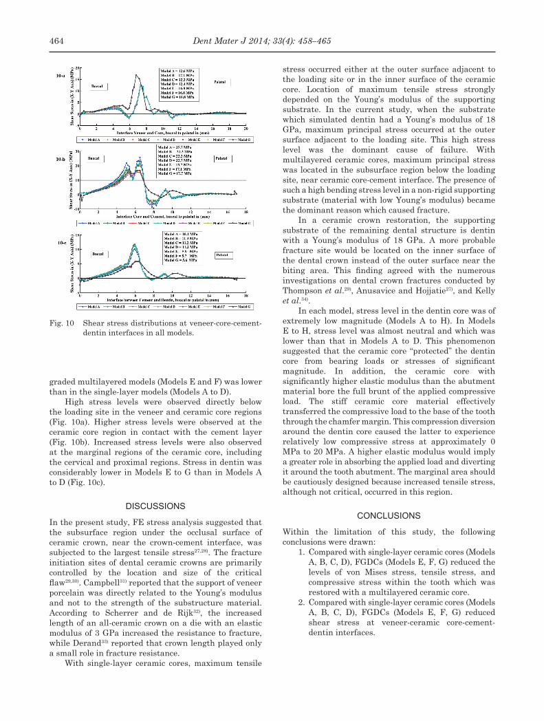
Fig. 10 Shear stress distributions at veneer-core-cement-dentin interfaces in all models.
graded multilayered models (Models E and F) was lower than in the single-layer models (Models A to D).
High stress levels were observed directly below the loading site in the veneer and ceramic core regions (Fig. 10a). Higher stress levels were observed at the ceramic core region in contact with the cement layer (Fig. 10b). Increased stress levels were also observed at the marginal regions of the ceramic core, including the cervical and proximal regions. Stress in dentin was considerably lower in Models E to G than in Models A to D (Fig. 10c).
DISCUSSIONS
In the present study, FE stress analysis suggested that the subsurface region under the occlusal surface of ceramic crown, near the crown-cement interface, was subjected to the largest tensile stress27,28). The fracture initiation sites of dental ceramic crowns are primarily controlled by the location and size of the critical flaw29,30). Campbell31) reported that the support of veneer porcelain was directly related to the Young’s modulus and not to the strength of the substructure material. According to Scherrer and de Rijk32), the increased length of an all-ceramic crown on a die with an elastic modulus of 3 GPa increased the resistance to fracture, while Derand33) reported that crown length played only a small role in fracture resistance.
With single-layer ceramic cores, maximum tensile
stress occurred either at the outer surface adjacent to the loading site or in the inner surface of the ceramic core. Location of maximum tensile stress strongly depended on the Young’s modulus of the supporting substrate. In the current study, when the substrate which simulated dentin had a Young’s modulus of 18 GPa, maximum principal stress occurred at the outer surface adjacent to the loading site. This high stress level was the dominant cause of failure. With multilayered ceramic cores, maximum principal stress was located in the subsurface region below the loading site, near ceramic core-cement interface. The presence of such a high bending stress level in a non-rigid supporting substrate (material with low Young’s modulus) became the dominant reason which caused fracture.
In a ceramic crown restoration, the supporting substrate of the remaining dental structure is dentin with a Young’s modulus of 18 GPa. A more probable fracture site would be located on the inner surface of the dental crown instead of the outer surface near the biting area. This finding agreed with the numerous investigations on dental crown fractures conducted by Thompson et al.29), Anusavice and Hojjatie27), and Kelly et al.34).
In each model, stress level in the dentin core was of extremely low magnitude (Models A to H). In Models E to H, stress level was almost neutral and which was lower than that in Models A to D. This phenomenon suggested that the ceramic core “protected” the dentin core from bearing loads or stresses of significant magnitude. In addition, the ceramic core with significantly higher elastic modulus than the abutment material bore the full brunt of the applied compressive load. The stiff ceramic core material effectively transferred the compressive load to the base of the tooth through the chamfer margin. This compression diversion around the dentin core caused the latter to experience relatively low compressive stress at approximately 0 MPa to 20 MPa. A higher elastic modulus would imply a greater role in absorbing the applied load and diverting it around the tooth abutment. The marginal area should be cautiously designed because increased tensile stress, although not critical, occurred in this region.
CONCLUSIONS
Within the limitation of this study, the following conclusions were drawn:
1. Compared with single-layer ceramic cores (Models A, B, C, D), FGDCs (Models E, F, G) reduced the levels of von Mises stress, tensile stress, and compressive stress within the tooth which was restored with a multilayered ceramic core.
2. Compared with single-layer ceramic cores (Models A, B, C, D), FGDCs (Models E, F, G) reduced shear stress at veneer-ceramic core-cement-dentin interfaces.
464 Dent Mater J 2014; 33(4): 458–465
ACKNOWLEDGMENT
This investigation was supported by grants from the University of Malaya, IPPP (PV020-2011B (IPPP) and RG512-13HTM (UMR)). In addition, this study was partially supported by a High Impact Research (HIR) grant from the Ministry of Higher Education, Malaysia (HIR-MOHE-16001-00-D000001).
REFERENCES
1) Lawn BR, Deng Y, Lloyd IK, Janal MN, Rekow ED, Thompson VP. Materials design of ceramic-based layer structures for crowns. J Dent Res 2002; 81: 433-438.
2) Conrad HJ, Seong WJ, Pesun IJ. Current ceramic materials and systems with clinical recommendations: a systematic review. J Prosthet Dent 2007; 98: 389-404.
3) Rekow D, Thompson VP. Engineering long term clinical success of advanced ceramic prostheses. J Mater Sci Mater Med 2007; 18: 47-56.
4) Chevalier J, Gremillard, L. Ceramics for medical applications: a picture for the next 20 years. J Europ Ceram Soc 2009; 29: 1245-1255.
5) Huang M, Rahbar N, Wang R, Thompson V, Rekow D, Soboyejo WO. Bioinspired design of dental multilayers. Materials Science and Engineering A 2007; 464: 315-320.
6) Della Bona A, Borba M, Benetti P, Duan Y, Griggs JA. Three-dimensional finite element modelling of all-ceramic restorations based on micro-CT. J Dent 2013; 41: 412-419.
7) Toparli M, Gokay N, Aksoy T. Analysis of a restored maxillary second premolar tooth by using three-dimensional finite element method. J Oral Rehabil 1999; 26: 157-164.
8) Ausiello P, Apicella A, Davidsonc CL, Rengo S. 3D-finite element analyses of cusp movements in a human upper premolar, restored with adhesive resin-based composites. J Biomech 2001; 34: 1269-1277.
9) Fischer H, Weber M, Marx R. Lifetime prediction of all-ceramic bridges by computational methods. J Dent Res 2003; 82: 238-242.
10) Dittmer MP, Kohorst P, Borchers L, Stiesch-Scholz M. Finite element analysis of a four-unit all-ceramic fixed partial denture. Acta Biomater 2009; 5: 1349-1355.
11) Dejak B, Młotkowski A, Langot C. Three-dimensional finite element analysis of molars with thin-walled prosthetic crowns made of various materials. Dent Mater 2012; 28: 433-441.
12) Hedia HS, Mahmoud NA. Design optimization of functionally graded dental implant. Biomed Mater Eng 2004; 14: 133-143.
13) Yang J, Xiang HJ. A three-dimensional finite element study on the biomechanical behavior of an FGBM dental implant in surrounding bone. J Biomech 2007; 40: 2377-2385.
14) Wang F, Lee HP, Lu C. Thermal-mechanical study of functionally graded dental implants with the finite element method. J Biomed Mater Res A 2007; 80: 146-158.
15) Watari F, Yokoyama A, Omori M, Hirai T, Kondo H, Uo M, Kawasaki T. Biocompatibility of materials and development to functionally graded implant for bio-medical application.
17) De Jager N, de Kler M, van der Zel JM. The influence of different core material on the FEA-determined stress distribution in dental crowns. Dent Mater 2006; 22: 234-242.
18) Rees JS. An investigation into the importance of the periodontal ligament and alveolar bone as supporting structures in finite element studies. J Oral Rehabil 2001; 28: 425-432.
19) DeHoff PH, Anusavice KJ, Hojjatie B. Thermal incompatibility analysis of metal-ceramic systems based on flexural displacement data. J Biomed Mater Res 1998; 41: 614-623.
20) Rees JS, Jacobsen PH. Elastic modulus of the periodontal ligament. Biomaterials 1997; 18: 995-999.
21) ABAQUS 2010. Manual Abaqus/CAE Professional version 6.10.1, Abaqus Inc., Simulia, Valley St., Providence, USA.
22) Kohorst P, Herzog TJ, Borchers L, Stiesch-Scholz M. Load-bearing capacity of all-ceramic posterior four-unit fixed partial dentures with different zirconia frameworks. Eur J Oral Sci 2007; 115: 161-166.
23) Toparli M, Aykul H, Aksoy T. Stress distribution associated with loaded acrylic-metal-cement crowns by using finite element method. J Oral Rehabil 2002; 29: 1108-1114.
24) White SN, Miklus VG, McLaren EA, Lang LA, Caputo AA. Flexural strength of a layered zirconia and porcelain dental all-ceramic system. J Prosthet Dent 2005; 94: 125-131.
25) Hench LL. Bioceramics: from concept to clinic. J Am Ceram Soc 1991; 74: 1487-1510.
26) Denisova LA, Maev RG, Poyurovskaya IY, Grineva TV, Denisov AF, Maeva EY, Bakulin EY. The use of acoustic microscopy to study the mechanical properties of glass-ionomer cement. Dent Mater 2004; 20: 358-363.
27) Anusavice KJ, Hojjatie B. Tensile stress in glass-ceramic crowns: effect of flaws and cement voids. Int J Prosthodont 1992; 5: 351-358.
28) Scherrer SS, de Rijk WG. The fracture resistance of all-ceramic crowns on supporting structures with different elastic moduli. Int J Prosthodont 1993; 6: 462-467.
29) Thompson JY, Anusavice KJ, Naman A, Morris HF. Fracture surface characterization of clinically failed all-ceramic crowns. J Dent Res 1994; 73: 1824-1832.
30) Kelly JR, Tesk JA, Sorensen JA. Failure of all-ceramic fixed partial dentures in vitro and in vivo: analysis and modeling. J Dent Res 1995; 74: 1253-1258.
31) Campbell SD. A comparative strength study of metal ceramic and all-ceramic esthetic materials: modulus of rupture. J Prosthet Dent 1989; 62: 476-479.
32) Scherrer SS, de Rijk WG. The effect of crown length on the fracture resistance of posterior porcelain and glass-ceramic crowns. Int J Prosthodont 1992; 5: 550-557.
33) Derand T. Effect of variation of the shape of the core on stresses in loaded model of a porcelain crown. Odontol Revy 1974; 25: 11-26.
34) Kelly JR, Giordano R, Pober R, Cima MJ. Fracture surface analysis of dental ceramics: clinically failed restorations. Int J Prosthodont 1990; 3: 430-440.