3D printing cement based ink, and it’s application within the construction industry
Zhu Jianchao*, Tao Zhang Mansour Faried, and Chen Wengang China State Construction Engineering Corporation (Middle East) Engineering Department 1 Lake Tower Plaza, Dubai, United Arab Emirates
Abstract. The 3D printing technology is the engine key of the third industrial revolution, after introduction of the automation in the eighteenth century and the concept of mass production in early of twentieth century. 3D printing technology now offers the magic solution to balance both the benefits, and overcome the major associated problem with the previous concept which was the need of repetition. The 3D printing technology has two main critical success factors: the printing machine and the printing material (ink). This paper focusses on cementitious-based materials and the ability to utilize the technology in the construction industry. The research took a qualitative approach based on previous literature reviews as well as in-house research results carried out by the authors’ employer Research and Development Center. The paper summarizes the approach towards to an appropriate mix design which can achieve the requirement of the printing process, and overcome the current constraints which are hindering the wide application of 3D print in construction industry. The authors believe that the research topic and result will have great impact on pushing the construction industry forward towards achieving the UAE Government’s strategy and target to achieve twenty-five percent (25%) of the buildings in Dubai by the year of 2030 relying on the 3D printing methodology. The research also concluded that even though the technology is adding a great value to the construction industry, it must be remembered that the technology is still in its infancy, and further research is required to achieve even higher strength printing materials that would be workable in multi-story buildings without the need of additional steel reinforcement.
1 Introduction
The three-dimensional (3D) printing technology concept has been known about since the 1980’s. It is always promoted as a major form of innovation in many industries, but in fact, research on the topic to date extends for almost 4 decades [1]. The technology application with the construction Industry is attracting field specialist interest day after day for the last few years, aiming to develop a giant scale 3D printer which could print the whole or a part of construction buildings, theoretically in any form or design [2].
3D printing technology is a form of Additive Manufacturing (AM), where a three dimensional object solid will be formed through the sequence-laying of horizontal layers
one on top of other [3]. There are hundreds of trials of deploying that concept in different forms, different materials and different machines.
According to Literatures, the two main parameters controlling the process of the 3D printing are the printing machine, and the printing ink, which accordingly could determine what kind of product the process could produce [4]. However, for construction purposes, there were 3 main categories that all the trials will fall under: Contour Crafting Method, D-Shape method, and Concrete Printing Method [5].
Each of the above processes will have a different objective, and then different forms of application.
The Contour Crafting Method is targeting the printing speed and productivity, so it is a kind of low resolution printer that is the most common method and what experts are aiming to develop further for mass production and mass construction [6], due to high speed of printing, a certain limitation over material strength and building shapes are associated with this method.
The D-Shape Method on the other hand, is targeting the complexity of the printed element; it works in different methodology as the machine is laying a full layer of fine sand and loose material, then the printer nozzle will go over and apply a form of glue as a binder on the locations which is required to be solid. That method is very slow, but it can produce both high resolution, and complicated objects, especially as it uses the loose material as a bed to support the suspended and horizontal surfaces, which the other 2 machines cannot do [7].
The third category of machines are what called as concrete printers or “Concjet”.Those machines are using the same method of printing as the Contour Crafting Method as it pre-mixes the printing material before printing, but the difference here that it goes in smaller thickness of layers with lower speed of printing which allows to use higher strength of concrete. However, with this process, the low printing speed is putting a major limitation on the productivity and object size. [5]
This paper will focus on the Contour Crafting Method, and will represent some of laboratory test results carried out by the Author’s in-house research and development center in Beijing - China, which aimed to develop a machine and printing material that could be used in rapid construction and 3D printing for building. The paper’s scope will be more focused on the cement-based printing ink and how to control its variable parameters in order to fit the purpose in terms of fluidity, workability, setting time, initial strength and final strength.
2 Cement-based printing ink For the last 100 years cement has been considered as the master raw material for construction, the cement used is mainly one of the 3 major types: ordinary Portland cement (OPC), calcium-aluminate Cement (CAC) and sulphoaluminate cement (SAC).The three types of cements have a different characteristics and accordingly different applications. OPC is the most commonly-used cement material and recognized widely for its high strength and stability as well as its low cost, while its disadvantage is the longer setting time comparing to other types. The other 2 types provide a shorter setting time with a high early strength capacity which make them more fit to several special engineering applications such as high temperature application and quick repair in emergency situations.
This paper mainly focusses on both of OPC and SAC as a principal raw material for the cementitious 3D printing Ink, while CAC has been excluded due to its lower final strength [9] which requires additional researches and tests and will be the scope of afuture paper, currently under progress. The research intends to examine the above-
DOI: 10.1051/, 02003 (2017) 712001MATEC Web of Conferences 20 matecconf/201ASCMCES-17
2003
2
mentioned materials (OPC & SAC) for their different properties such as setting time (initial and final), workability and durability, and mechanical properties such as compressive strength and flexural strength.
SAC has been extensively used in China for wide variety of building works, especially for those buildings located in very low temperature zones, ports projects, underground construction projects and precast concrete members it has a proven track record of successful application and it is fit for the purpose it has been planned for. The SAC has a short settingtime, high strength at early stage, and steadily developing strength at later stage. These properties are well-suited and desirable for the 3D printing process, as well as the architectural requirement of the technology. Therefore research into the enhancement of SAC’s setting time and workability, has resulted in the development of an SAC-based 3D printing material. Furthermore, these material properties and performance have been analyzed and tested.
OPC is the most widely-used cement worldwide due to its low cost, availability of manufacturers and suppliers, stable performance and many other advantages. OPC has also been used to produce the 3D printing materials, However OPC, characterized by its slow hydration, longer setting time and lower strength when compared to SAC hinders itsapplication in the 3D printing technology.
In principle, the 3D printing process requirement in terms of materials can be summarized as follows; 1) controllable and flexible setting time, 2) have a certain level of workability and fluidity to allow material to flow through the printing head while still having the ability to bear the above layer’s weight after printing, 3) to have a proper bonding between the Various layers. That bonding should be uniform in all directions. 4) Should have high early strength to ensure that material can support own weight and super-imposed layers as, with the progress of printing, the bottom layers will be required to take the load of the whole wall height in 2-3 hours.
The above 4 criteria have been set as the material development research objective in order to reach to the specific mix design which can fit the purpose.
3 Selection of raw materials and method
3.1 Cement
For the test purpose, samples for both materials have been obtained for the availablecommercial materials in Chinese Local Market, the chemical composition for the tested samples and their performance parameters could be seen below in table 1 and table 2
Table 1. Chemical composition of tested samples.
T Al2O3 CaO SO3 SiO2 Fe2O3 MgOLoss on
ignition
SAC 35.17 42.54 10.79 6.13 1.53 1.24 2.10
OPC 6.65 58.93 2.54 24.12 3.78 0.79 3.19
DOI: 10.1051/, 02003 (2017) 712001MATEC Web of Conferences 20 matecconf/201ASCMCES-17
2003
3
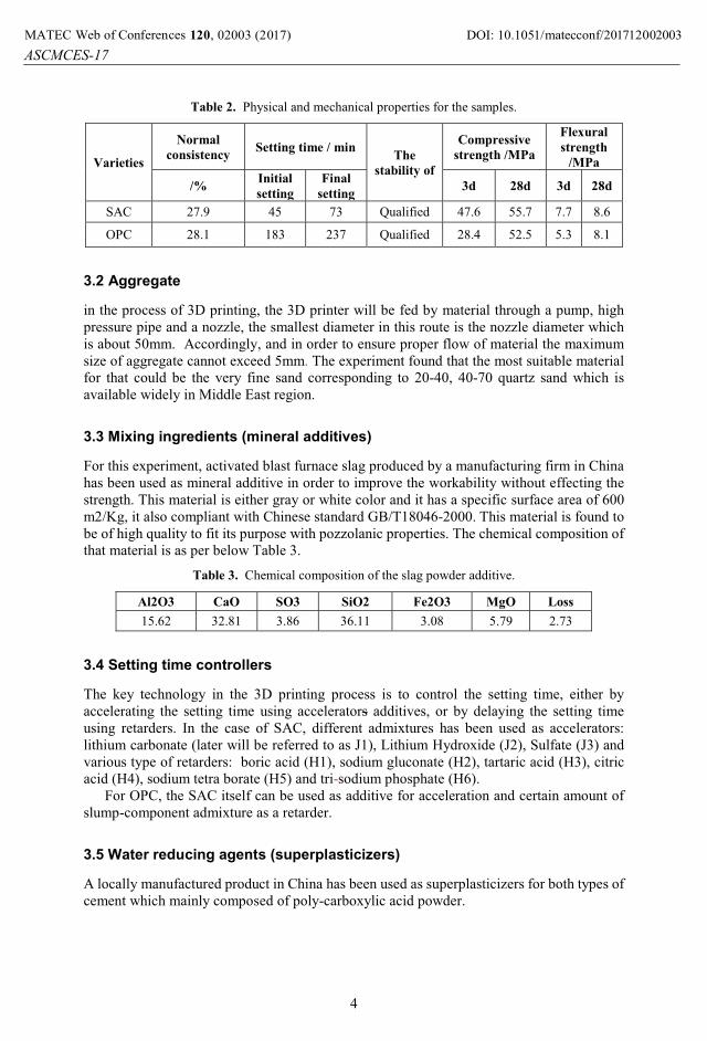
Table 2. Physical and mechanical properties for the samples.
Varieties
Normal
consistencySetting time / min
The
stability of
Compressive
strength /MPa
Flexural
strength
/MPa
/%Initial
setting
Final
setting3d 28d 3d 28d
SAC 27.9 45 73 Qualified 47.6 55.7 7.7 8.6
OPC 28.1 183 237 Qualified 28.4 52.5 5.3 8.1
3.2 Aggregate
in the process of 3D printing, the 3D printer will be fed by material through a pump, high pressure pipe and a nozzle, the smallest diameter in this route is the nozzle diameter which is about 50mm. Accordingly, and in order to ensure proper flow of material the maximum size of aggregate cannot exceed 5mm. The experiment found that the most suitable material for that could be the very fine sand corresponding to 20-40, 40-70 quartz sand which is available widely in Middle East region.
3.3 Mixing ingredients (mineral additives)
For this experiment, activated blast furnace slag produced by a manufacturing firm in China has been used as mineral additive in order to improve the workability without effecting the strength. This material is either gray or white color and it has a specific surface area of 600 m2/Kg, it also compliant with Chinese standard GB/T18046-2000. This material is found to be of high quality to fit its purpose with pozzolanic properties. The chemical composition of that material is as per below Table 3.
Table 3. Chemical composition of the slag powder additive.
Al2O3 CaO SO3 SiO2 Fe2O3 MgO Loss
15.62 32.81 3.86 36.11 3.08 5.79 2.73
3.4 Setting time controllers
The key technology in the 3D printing process is to control the setting time, either by accelerating the setting time using accelerators additives, or by delaying the setting time using retarders. In the case of SAC, different admixtures has been used as accelerators: lithium carbonate (later will be referred to as J1), Lithium Hydroxide (J2), Sulfate (J3) and various type of retarders: boric acid (H1), sodium gluconate (H2), tartaric acid (H3), citric acid (H4), sodium tetra borate (H5) and tri-sodium phosphate (H6).
For OPC, the SAC itself can be used as additive for acceleration and certain amount of slump-component admixture as a retarder.
3.5 Water reducing agents (superplasticizers)
A locally manufactured product in China has been used as superplasticizers for both types of cement which mainly composed of poly-carboxylic acid powder.
DOI: 10.1051/, 02003 (2017) 712001MATEC Web of Conferences 20 matecconf/201ASCMCES-17
2003
4
3.6 Volume stabilizer
Several components have been developed in house to maintain the concrete volume and minimize the shrinkage has been used with both types of cement.
4 Measurements standardsChinese standards have been used as a reference to measure and evaluate the material parameters and performance: Chinese standard GB/T 1346-2011 has been used to test the water requirement for normal consistency, setting time and soundness of OPC. Chinese standard GB/T 17671-1999 & JGJ70-2009 has been used to measure the cement strength.Chinse standard GB/T 2419-2005 has been used to assess the fluidity of the cement mortar. Lastly, Chinese standard GB/T 50082-2009 has been used to measure the long-term performance and durability of ordinary concrete as well as material chemical resistance and anti-carbonation durability. For those tests, commercial equipment has been deployed to measure the concrete viscosity and concrete behavior in terms of hydration and development of strength across the time.
The material curing has been made using a curing box at temperature of 20 �, and humidity of 95%. Testing cubes have been made in the size of 25mm × 25mm × 280mm.
5 Setting time control The material that has been developed and tested is still considered as a cement mortar, although it has been enhanced and improved to fit the technology requirement through chemicals additives. The research tested both SAC and OPC, and tried to adjust the setting time, workability, and early strength to meet the desired requirement of the 3D printing process. There is a lot of previous research which concluded that cement-sand ratio of 1:1can lead to the best workability and mechanical properties of the mortar. The same ratio has been considered in this research as well.
A super plasticizer agent has been added to reduce the water content, and therefore higher final strength could be achieved accordingly a water/cement ratio of 0.35 – 0.38 has been used. Furthermore, by adding mineral admixture, composite volume stabilizer and other additives it is possible to improve material mechanical properties and setting time control for SAC.
5.1 Selection of retarder
Since SAC is characterized by its rapid hardening, the addition of retarder to the mix is strongly invited, especially when the surrounded environment has a high temperature, the retarder in concept will generate an insoluble thin film around the cement particles whichwill act as a barrier and reduce the hydration rate of cement and subsequently will delay the hardening process. For this study, 6 different types of retarders have been tested individually: boric acid ( H1), sodium gluconate (H2), tartaric acid (H3), citric acid (H4), sodium tetra borate (H5), tri-sodium phosphate (H6), The effect of each of the those retarders on the SAC setting time can be seen as shown in Figure 1 & Figure 2 below.
DOI: 10.1051/, 02003 (2017) 712001MATEC Web of Conferences 20 matecconf/201ASCMCES-17
2003
5
0.00 0.05 0.10 0.15 0.20 0.25 0.300
100
200
300
400
500
600
700
800
Setti
ng T
ime
The mixing amount of H1(%)
jelling timefinal setting time
0.00 0.05 0.10 0.15 0.20 0.25 0.3020406080
100
120140160180200
Set
ting
time(
min
)
The mixing amount of H2(%)
jelling time final setting time
0.00 0.05 0.10 0.15 0.20 0.25 0.30
20
40
60
80
100
120
140
Set
ting
Tim
e(m
in)
The mixing amount of H3(%)
jelling timefinal setting time
Fig. 1. Effect of retarders (H1, H2, and H3) on the setting time of SAC.
0.00 0.02 0.04 0.06 0.08 0.1025
30
35
40
45
50
Set
ting
Tim
e(m
in)
The mixing amount of H4(%)
jelling timefinal setting time
0.05 0.10 0.15 0.20 0.25 0.3020406080
100120140160180200
Set
ting
Tim
e(m
in)
The mixing amount of H5(%)
jelling timefinal setting time
0.0 0.2 0.4 0.6 0.8 1.020
30
40
50
60
70
80
90
100
Setti
ng T
ime(m
in)
The mixing amount of H6(%)
jelling timefinal setting time
Fig. 2. Effect of retarders (H4, H5, and H6) on the setting time of SAC.
Figure 1 and Figure 2 above explain the behavior of mortar setting time with the change of the quantity of the retarding agent added for each material separately. From the analysis of the above, some of those agents have been excluded due to undesired and inconsistent development of setting time delay and accordingly they are not suitable for the 3D printing purpose.
DOI: 10.1051/, 02003 (2017) 712001MATEC Web of Conferences 20 matecconf/201ASCMCES-17
2003
6
5.2 Selection of accelerating agent
The accelerating agents is just an opposite of the retarder in its action, and it is essential that it is used specially in a very low temperature environment to order to gain higher early strength, and also in cases where certain engineering mixes are required to achieve high early strength in a short time. For this study, three different materials have been tested as an accelerating agents: lithium carbonate (J1), lithium hydroxide (J2) and calcium chloride (J3).The effect of those agents on SAC setting time are shown in Figure 3.
0.00 0.05 0.10 0.15 0.20 0.25 0.30
5101520253035404550
Set
ting
Tim
e(m
in)
The mixing amount of J1(%)
jelling timefinal setting time
a
0.00 0.02 0.04 0.06 0.08 0.10
5101520253035404550
Set
ting
Tim
e(m
in)
The mixing amount of J2 (%)
jelling timefinal setting time
b
0.00 0.02 0.04 0.06 0.08 0.105
10
15
20
25
30
35
40
45
50
Set
ting
Tim
e(m
in)
The mixing amount of J3(%)
jelling timefinal setting time
c
Fig. 3. Effect of accelerating agents (J1, J2, and J3) on the setting time of SAC.
By analysing the above graphs, it can be concluded that J1 can reduce the setting time to half when using it at the ratio of 0.01% (17 minutes), which can be reduced further to 9 minutes at ratio of 0.05% and to 5 minutes when the ratio is increased to 0.3%. For J2, as it has strong base, accordingly it will have a stronger effect on reducing the initial setting time comparing to J1 and J3, so the setting time can be shortened to 9 minutes with the ratio of 0.01%. ForJ3, it has a good performance with OPC, however its preference for SAC is not favourable.
In term of developing the strength, the below Figure 4 will show the difference between the three accelerators comparing with the case when the cement is used with any accelerators over different duration of time.
2h 1d 3d 28d0
5
10
15
20
25
30
35
40
45
Comp
ressiv
e stre
ngth(
MPa)
curing time
J1 J2 J3
Fig. 4. Effect of early strength agents on the strength of SAC.
DOI: 10.1051/, 02003 (2017) 712001MATEC Web of Conferences 20 matecconf/201ASCMCES-17
2003
7
5.3 Testing results
Several trials have been made using each of those chemical agents and different performance measures have been taken to verify the impact of each agent separately. The experimentshave shown the following:
A) Some of those tested retarders were found to have a counter-productive reaction at the early stage where, at certain dosage it acted as an accelerator. That is totally unsuitable for the 3D printing process and accordingly they were excluded.
B) With some other retarders, the increment of the dosage would dramatically increase the setting time disproportionally to the dosage increment value, and that also is not preferable to 3D printing process and accordingly they have been excluded.
C) Some of the tested retarders were found to be characterized with unstable and unpredictable performance with the dosage increment that also has been excluded.
D) Some retarders found to be fit for application with a certain amount of minimumdosage, since the reaction performance below that dosage is not stable. Although it is not highly preferred, that particular retarder was not excluded as it could act better when mixing with other types of retarders.
E) Some of the accelerator agents found to be with a minor impact on SAC comparing to OPC and since complete control over material setting time is targeted then that particular accelerator has been excluded.
F) Generating a composite retarding agent by certain mix of different retarders has delivered a more desired performance compared to the performance of each component acting individually.
G) To obtain the ultimate time-control agent, a further composite solution has been generated (referred to later as JH) by adding an accelerating agent to previously concluded composite retarding agent. Using several experiments on the dosage, the relationship between the JH dosage and setting time of concrete and early strength of concrete was calculated.
H) Different compositions for JH agent were developed (JH1- JH6) with different ingredients of retarders and accelerators, the below table 4 reflects the value of initial setting time and final setting time of each.
Table 4. Initial and final setting time for composite agent JH1-JH6
DOI: 10.1051/, 02003 (2017) 712001MATEC Web of Conferences 20 matecconf/201ASCMCES-17
2003
8
6.1 Mechanical properties
The samples for test is collected by cutting it off from a full size printed walls, the samples have been tested for the compressive and flexural strength, and Table 5 below represents the best results obtained when using JH-2 and a setting time control agent.
Table 5. Flexural and compressive strength of specimen.
Strength
Flexural strength
/MPa
Compressive
strength/MPa
2h 28d 2h 28d
Molding specimens 2.4 8.3 13.5 58.6
According to results in Table 5 above, the early compressive strength after 2 hours is more than 10MPa, which is sufficient to support the wall full weight. Figures 5 to 8 below represent different directions of flexural strength, compressive strength and flexural failure morphology.
Figure 9 below show a comparison between the different directions of Flexural strength and compression strength. The results proposed a considerable difference between different directions of loading due to higher bonding strength within each layer compared to bonding between different layers, which need to be taken in account during the design. However, the vertical compressive strength can still reach up to 44.6 MPa, which is good enough to ensure safety of the structure.
DOI: 10.1051/, 02003 (2017) 712001MATEC Web of Conferences 20 matecconf/201ASCMCES-17
2003
9
Fig. 9. Comparison of the compressive strength of cutting specimens and molding specimens.
6.2 Chemical properties
The durability of the material is directly related to its chemical properties and its resistance to various chemicals. The printed material has been tested for various chemical tests as following:
� Chloride permeability Rapid chloride permeability test method to measure the migration of the chloride ions within the material. The below Table 5 represent the relation between chloride ion permeability of the concrete and electric flux. Table 6 represents measurements taken for 3 different samples of 3D print materials, according to both Tables 5 and 6, the permeability of the 3 D printed materials can be classified as “medium”.
Table 5: The corresponding relationship between electric flux and chloride ion permeability ofconcrete.
Electric flux/CChloride ion
permeabilityConcrete
> 4000 High High water-cement ratio (0.6)2000 4000 medium Medium water cement ratio (0.4 ~ 0.5)1000 2000 low Low water cement ratio (0.3 ~ 0.4)100 1000 very low
Emulsion modified concrete< 100 silica fume concrete etc.
Table 6: Results of electric flux for the 3D printing materials.
NO. 3D-1 3D-2 3D-3
Electric flux/C 2441Q 2332Q 2249Q
� Resistance to freeze-thaw cycle performance. The rapid freeze-thaw method has been used to test the thermal performance of the 3D printing materials, as it measures the loss in weight and the relative dynamic elastic modulus after exposing the material to 200 cycles of Freeze-thaw. The results of the test are summarized in table 7 below.
Table 7: The freeze-thaw cycle experimental results of building 3D printing materials.
Times 0 time 100 times 200times 200 times
DOI: 10.1051/, 02003 (2017) 712001MATEC Web of Conferences 20 matecconf/201ASCMCES-17
2003
10
ItemWeight
/g
Dynamic modulus/
GPaWeight /g
Dynamic modulus/
GPaWeight /g
Dynamic modulus/
GPa
Weight Loss /%
Relative dynamic modulus
/%9171 33.39 9187 32.86 9201 32.94 0 97.3%
The result of table 7 above indicates that the materials didn’t encounter weight loss after 200 cycles of Freeze-thaw. Accordingly the materials can be used safely in cold environments.
� Impermeability and carbonation resistance. The concrete has six grades to classify its Impermeability, which are P4, P6, P8, P10, P12, and more than P12 [8], which basically represent the materials ability to deal with water pressure in the impermeability test, and accordingly the waters ability to penetrate the material.Figure 10 below indicates that the tested material can be classified as “greater that P12 with average seepage height of 24.5 mm.
Fig. 10. Water penetration height under pressure P12.
Drying shrinkage of building 3D printing materials Figure 11 below represents a comparison between the 3D printing material and the normal cement mortar in terms of volume shrinkage:
0 5 10 15 20 25 30
-0.30
-0.25
-0.20
-0.15
-0.10
-0.05
0.00
0.05
Expa
nsion
/ %
A
Cement-based 3D printing materials (20 RH=60 %, dry air curing) PO. 42.5 cement mortar(20 RH=60 %, dry air curing)
Curing time (days)
Fig. 11. Comparison of shrinkage of PO42.5 standard cement mortar and building 3D printing materials.
From Figure 11 above, it is obvious that the shrinkage of 3D printing mortar is much less compared to normal mortar which is a considerable added-value feature.
7 Application of cement-based building 3D printing materials
DOI: 10.1051/, 02003 (2017) 712001MATEC Web of Conferences 20 matecconf/201ASCMCES-17
2003
11
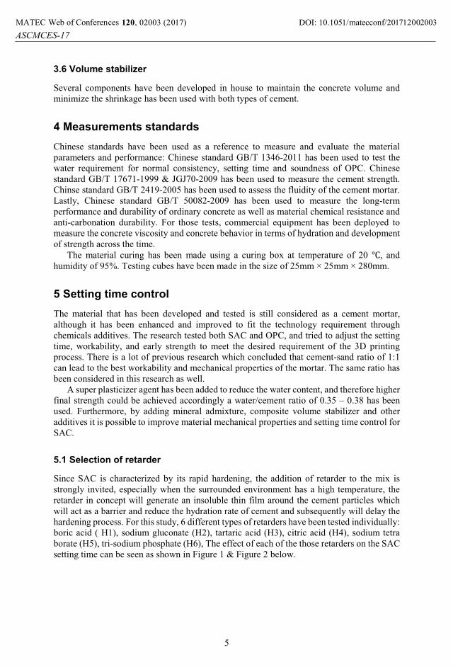
Printing Ink development can’t go alone with the development of printing machine and printing software, The Technical Center of CSCEC in Beijing has developed various versions of printing machines in different sizes as shown below in Figures 12 to Figure 16
Fig. 12. Small-sized building 3D printer. Fig. 13. Large-sized building 3D printer.
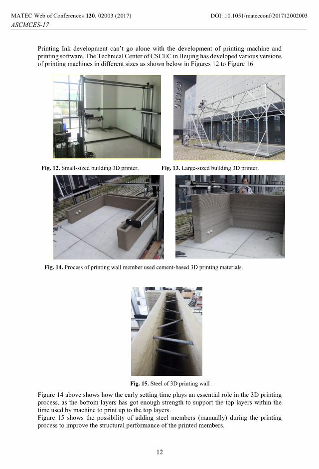
Fig. 14. Process of printing wall member used cement-based 3D printing materials.
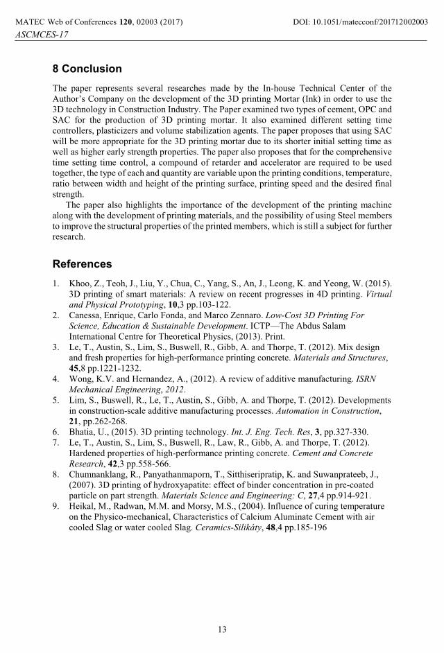
Fig. 15. Steel of 3D printing wall .
Figure 14 above shows how the early setting time plays an essential role in the 3D printing process, as the bottom layers has got enough strength to support the top layers within the time used by machine to print up to the top layers.Figure 15 shows the possibility of adding steel members (manually) during the printing process to improve the structural performance of the printed members.
DOI: 10.1051/, 02003 (2017) 712001MATEC Web of Conferences 20 matecconf/201ASCMCES-17
2003
12
8 ConclusionThe paper represents several researches made by the In-house Technical Center of the Author’s Company on the development of the 3D printing Mortar (Ink) in order to use the 3D technology in Construction Industry. The Paper examined two types of cement, OPC and SAC for the production of 3D printing mortar. It also examined different setting time controllers, plasticizers and volume stabilization agents. The paper proposes that using SAC will be more appropriate for the 3D printing mortar due to its shorter initial setting time as well as higher early strength properties. The paper also proposes that for the comprehensive time setting time control, a compound of retarder and accelerator are required to be used together, the type of each and quantity are variable upon the printing conditions, temperature, ratio between width and height of the printing surface, printing speed and the desired final strength.
The paper also highlights the importance of the development of the printing machine along with the development of printing materials, and the possibility of using Steel members to improve the structural properties of the printed members, which is still a subject for further research.
References1. Khoo, Z., Teoh, J., Liu, Y., Chua, C., Yang, S., An, J., Leong, K. and Yeong, W. (2015).
3D printing of smart materials: A review on recent progresses in 4D printing. Virtual
and Physical Prototyping, 10,3 pp.103-122.2. Canessa, Enrique, Carlo Fonda, and Marco Zennaro. Low-Cost 3D Printing For
Science, Education & Sustainable Development. ICTP—The Abdus Salam International Centre for Theoretical Physics, (2013). Print.
3. Le, T., Austin, S., Lim, S., Buswell, R., Gibb, A. and Thorpe, T. (2012). Mix design and fresh properties for high-performance printing concrete. Materials and Structures,45,8 pp.1221-1232.
4. Wong, K.V. and Hernandez, A., (2012). A review of additive manufacturing. ISRN
Mechanical Engineering, 2012.5. Lim, S., Buswell, R., Le, T., Austin, S., Gibb, A. and Thorpe, T. (2012). Developments
in construction-scale additive manufacturing processes. Automation in Construction,21, pp.262-268.
6. Bhatia, U., (2015). 3D printing technology. Int. J. Eng. Tech. Res, 3, pp.327-330.7. Le, T., Austin, S., Lim, S., Buswell, R., Law, R., Gibb, A. and Thorpe, T. (2012).
Hardened properties of high-performance printing concrete. Cement and Concrete
Research, 42,3 pp.558-566.8. Chumnanklang, R., Panyathanmaporn, T., Sitthiseripratip, K. and Suwanprateeb, J.,
(2007). 3D printing of hydroxyapatite: effect of binder concentration in pre-coated particle on part strength. Materials Science and Engineering: C, 27,4 pp.914-921.
9. Heikal, M., Radwan, M.M. and Morsy, M.S., (2004). Influence of curing temperature on the Physico-mechanical, Characteristics of Calcium Aluminate Cement with air cooled Slag or water cooled Slag. Ceramics-Silikáty, 48,4 pp.185-196
DOI: 10.1051/, 02003 (2017) 712001MATEC Web of Conferences 20 matecconf/201ASCMCES-17