Three-dimensional plotted scaffolds with controlled pore size gradients: Effect of scaffold geometry on mechanical performance and cell seeding efficiency Jorge M. Sobral, Sofia G. Caridade, Rui A. Sousa, João F. Mano ⇑ , Rui L. Reis 3B’s Research Group – Biomaterials, Biodegradables and Biomimetics, University of Minho, Headquarters of the European Institute of Excellence on Tissue Engineering and Regenerative Medicine, AvePark, 4806-909 Taipas, Guimarães, Portugal Institute for Biotechnology and Bioengineering, PT Associated Laboratory, Guimarães, Portugal article info Article history: Received 16 June 2010 Received in revised form 26 October 2010 Accepted 1 November 2010 Available online 4 November 2010 Keywords: Tissue engineering Regenerative medicine Three-dimensional plotting Porosity gradient Seeding efficiency abstract Scaffolds produced by rapid prototyping (RP) techniques have proved their value for tissue engineering applications, due to their ability to produce predetermined forms and structures featuring fully intercon- nected pore architectures. Nevertheless, low cell seeding efficiency and non-uniform distribution of cells remain major limitations when using such types of scaffold. This can be mainly attributed to the inade- quate pore architecture of scaffolds produced by RP and the limited efficiency of cell seeding techniques normally adopted. In this study we aimed at producing scaffolds with pore size gradients to enhance cell seeding efficiency and control the spatial organization of cells within the scaffold. Scaffolds based on blends of starch with poly(e-caprolactone) featuring both homogeneously spaced pores (based on pore sizes of 0.75 and 0.1 mm) and pore size gradients (based on pore sizes of 0.1–0.75–0.1 and 0.75–0.1– 0.75 mm) were designed and produced by three-dimensional plotting. The mechanical performance of the scaffolds was characterized using dynamic mechanical analysis (DMA) and conventional compression testing under wet conditions and subsequently characterized using scanning electron microscopy and micro-computed tomography. Osteoblast-like cells were seeded onto such scaffolds to investigate cell seeding efficiency and the ability to control the zonal distribution of cells upon seeding. Scaffolds featur- ing continuous pore size gradients were originally produced. These scaffolds were shown to have inter- mediate mechanical and morphological properties compared with homogenous pore size scaffolds. The pore size gradient scaffolds improved seeding efficiency from 35% in homogeneous scaffolds to 70% under static culture conditions. Fluorescence images of cross-sections of the scaffolds revealed that scaf- folds with pore size gradients induce a more homogeneous distribution of cells within the scaffold. Ó 2010 Acta Materialia Inc. Published by Elsevier Ltd. All rights reserved. 1. Introduction Tissue engineering aims at restoring or regenerating a damaged tissue by combining cells with three-dimensional (3D) porous scaf- folds. After isolation and eventual in vitro expansion, cells are seeded on 3D scaffolds and implanted directly or at a later stage in the patient [1]. Control of the cellular micro-architecture inside the scaffolds is of great importance when developing tissue engi- neering constructs. Moreover, early studies suggest that the mi- cro-architecture of scaffolds might influence cell attachment and orientation and induce different biological behaviors [2–4]. Ulti- mately, optimizing and controlling these characteristics could lead to better implants when attempting to restore damaged tissues. Rapid prototyping (RP) is one of the most promising techniques for designing and producing scaffolds for tissue engineering appli- cations [5–11]. Many studies on the optimization of RP techniques and scaffolds fabricated by these techniques have been reported in the past few years [12–17]. The scaffolds are usually characterized by their 100% interconnected pores, fully computer controlled architecture and high porosities, which facilitate nutrient perfu- sion, essential to ensure cell viability. However, these techniques also present some drawbacks, including low resolution, which only allows fabrication of scaffolds with large pore sizes compared with the dimensions of a cell. This often leads to low cell seeding effi- ciencies (25–40%) and to a non-uniform distribution of cells along the scaffolds [18]. From a tissue engineering point of view it is known that high cell densities are closely related to improved tis- sue formation in 3D scaffolds [19–23]. However, achieving a high cell seeding efficiency is very difficult, mainly due to the intrinsic scaffold characteristics (large pore size, poor cell–material adhe- sion and open pore architecture, among others) and limited cell seeding techniques [24]. The shortage of cells upon seeding re- quires longer periods of cell culture in order to obtain viable con- structs. There is also some evidence that the growth of the cells 1742-7061/$ - see front matter Ó 2010 Acta Materialia Inc. Published by Elsevier Ltd. All rights reserved. doi:10.1016/j.actbio.2010.11.003 ⇑ Corresponding author. Address: 3B’s Research Group – Biomaterials, Biode- gradables and Biomimetics, AvePark, Zona Industrial da Gandra, S. Cláudio do Barco, 4806-909 Caldas das Taipas, Guimarães, Portugal. Tel.: +351 253510904; fax: +351 253510909. E-mail address: [email protected](J.F. Mano). Acta Biomaterialia 7 (2011) 1009–1018 Contents lists available at ScienceDirect Acta Biomaterialia journal homepage: www.elsevier.com/locate/actabiomat
Three-dimensional plotted scaffolds with controlled pore size gradients: Effectof scaffold geometry on mechanical performance and cell seeding efficiency
Jorge M. Sobral, Sofia G. Caridade, Rui A. Sousa, João F. Mano ⇑, Rui L. Reis3B’s Research Group – Biomaterials, Biodegradables and Biomimetics, University of Minho, Headquarters of the European Institute of Excellence on TissueEngineering and Regenerative Medicine, AvePark, 4806-909 Taipas, Guimarães, PortugalInstitute for Biotechnology and Bioengineering, PT Associated Laboratory, Guimarães, Portugal
a r t i c l e i n f o a b s t r a c t
Article history:Received 16 June 2010Received in revised form 26 October 2010Accepted 1 November 2010Available online 4 November 2010
1742-7061/$ - see front matter � 2010 Acta Materialdoi:10.1016/j.actbio.2010.11.003
⇑ Corresponding author. Address: 3B’s Research Ggradables and Biomimetics, AvePark, Zona Industrial d4806-909 Caldas das Taipas, Guimarães, Portugal. Tel.253510909.
Scaffolds produced by rapid prototyping (RP) techniques have proved their value for tissue engineeringapplications, due to their ability to produce predetermined forms and structures featuring fully intercon-nected pore architectures. Nevertheless, low cell seeding efficiency and non-uniform distribution of cellsremain major limitations when using such types of scaffold. This can be mainly attributed to the inade-quate pore architecture of scaffolds produced by RP and the limited efficiency of cell seeding techniquesnormally adopted. In this study we aimed at producing scaffolds with pore size gradients to enhance cellseeding efficiency and control the spatial organization of cells within the scaffold. Scaffolds based onblends of starch with poly(e-caprolactone) featuring both homogeneously spaced pores (based on poresizes of 0.75 and 0.1 mm) and pore size gradients (based on pore sizes of 0.1–0.75–0.1 and 0.75–0.1–0.75 mm) were designed and produced by three-dimensional plotting. The mechanical performance ofthe scaffolds was characterized using dynamic mechanical analysis (DMA) and conventional compressiontesting under wet conditions and subsequently characterized using scanning electron microscopy andmicro-computed tomography. Osteoblast-like cells were seeded onto such scaffolds to investigate cellseeding efficiency and the ability to control the zonal distribution of cells upon seeding. Scaffolds featur-ing continuous pore size gradients were originally produced. These scaffolds were shown to have inter-mediate mechanical and morphological properties compared with homogenous pore size scaffolds. Thepore size gradient scaffolds improved seeding efficiency from �35% in homogeneous scaffolds to �70%under static culture conditions. Fluorescence images of cross-sections of the scaffolds revealed that scaf-folds with pore size gradients induce a more homogeneous distribution of cells within the scaffold.
� 2010 Acta Materialia Inc. Published by Elsevier Ltd. All rights reserved.
1. Introduction for designing and producing scaffolds for tissue engineering appli-
Tissue engineering aims at restoring or regenerating a damagedtissue by combining cells with three-dimensional (3D) porous scaf-folds. After isolation and eventual in vitro expansion, cells areseeded on 3D scaffolds and implanted directly or at a later stagein the patient [1]. Control of the cellular micro-architecture insidethe scaffolds is of great importance when developing tissue engi-neering constructs. Moreover, early studies suggest that the mi-cro-architecture of scaffolds might influence cell attachment andorientation and induce different biological behaviors [2–4]. Ulti-mately, optimizing and controlling these characteristics could leadto better implants when attempting to restore damaged tissues.Rapid prototyping (RP) is one of the most promising techniques
ia Inc. Published by Elsevier Ltd. A
roup – Biomaterials, Biode-a Gandra, S. Cláudio do Barco,: +351 253510904; fax: +351
.
cations [5–11]. Many studies on the optimization of RP techniquesand scaffolds fabricated by these techniques have been reported inthe past few years [12–17]. The scaffolds are usually characterizedby their 100% interconnected pores, fully computer controlledarchitecture and high porosities, which facilitate nutrient perfu-sion, essential to ensure cell viability. However, these techniquesalso present some drawbacks, including low resolution, which onlyallows fabrication of scaffolds with large pore sizes compared withthe dimensions of a cell. This often leads to low cell seeding effi-ciencies (25–40%) and to a non-uniform distribution of cells alongthe scaffolds [18]. From a tissue engineering point of view it isknown that high cell densities are closely related to improved tis-sue formation in 3D scaffolds [19–23]. However, achieving a highcell seeding efficiency is very difficult, mainly due to the intrinsicscaffold characteristics (large pore size, poor cell–material adhe-sion and open pore architecture, among others) and limited cellseeding techniques [24]. The shortage of cells upon seeding re-quires longer periods of cell culture in order to obtain viable con-structs. There is also some evidence that the growth of the cells
in the scaffolds can be affected by the scaffold architecture due to alack of ingress of nutrients and metabolic product removal [25].Moreover, it is well established that an inhomogeneous distribu-tion of the cells upon seeding is associated with low rates of tissueformation [19], a less uniform tissue [23] and a different cell differ-entiation behavior [22]. Therefore, a low cell seeding efficiency andheterogeneous distribution of cells in RP scaffolds are major draw-backs of these scaffolds in tissue engineering applications, whichdemands further research into the optimization of scaffold archi-tectures and materials. One of the main aspects of scaffold archi-tecture is the pore structure, which is determined by the size,size distribution, geometry and continuity of the individual poreswithin the scaffold. The pore structure plays an essential role in cellmigration and adhesion, tissue formation, mechanical propertiesand nutrient diffusion, among other things. As mentioned before,RP might be used to easily control the scaffold architecture in orderto obtain better results in terms of combining enhanced tissuegrowth with adequate mechanical properties [17,26–31]. To ourknowledge there have been few experiments using gradient poresize or porosity 3D scaffolds to control the spatial organization ofcells and increase the seeding efficiency for tissue engineeringapplications [32–39], probably due to considerable difficulties inboth fabrication and correlating biological responses with scaffoldarchitecture. Previous work by our group has shown that cell seed-ing is less efficient when the cell culture medium travels from thetop of a scaffold through a porous structure having more directpaths for passage of the medium. In this study we hypothesize thatscaffolds produced by a one-step fabrication process featuring twopore size gradients along one direction can improve cell seedingefficiency as well as the spatial distribution of the cells withinthe scaffolds compared with scaffolds featuring homogeneouslyspaced pores. More tortuous conduits inside the scaffold should in-crease the residence time of cells in the scaffolds and increase thelikelihood of contact between the cells and the surface of thescaffold.
For these experiments we used a starch-based material starch/poly(e-caprolactone) blend (SPCL). Although SPCL can reduce cellproliferation rates [40], its low cytotoxicity in vitro [40,41], goodbiodegradability [42], and weak potential to stimulate an inflam-matory response in vivo [43] make it a promising material for tis-sue regeneration applications. The improved scaffold architecturesdeveloped in this study are expected to further improve the mim-icking of human tissue structures, as zonal variations in extracellu-lar matrix are usually found in connective tissues.
2. Materials and methods
2.1. 3D scaffold fabrication
The material studied in this work was a blend of corn starchwith poly(e-caprolactone) (30/70 wt.%, Novamont, Italy) as thismaterial has previously been optimized for use in 3D scaffolds pro-duced by 3D plotting and injection molding for tissue engineeringapplications [37,43]. SPCL granules were milled in an ultra-centrif-ugal mill (ZM-100, Retsch, Germany) with liquid nitrogen at 14,000r.p.m. in order to facilitate melting during processing. The scaffoldsused in all experiments were fabricated using 3D plotting (Bioplot-ter, EnvisionTec GmbH, Germany). Alternating layers were ori-ented at 90� to each other. The scaffolds were fabricated as5 � 5 � 5 mm cubes. The size of the scaffolds was due to the lowspeed of the 3D plotting process, which makes the production ofa significant number of larger scaffolds than the ones here difficult.Each layer was plotted using a layer thickness (d1) of 0.19 mm.Fig. 1 shows the dimensional parameters of the scaffolds produced.In this study various scaffold architectures were produced: two
homogeneous scaffolds exhibiting fiber spacings (d3) of 0.75(Homog 1) and 0.1 mm (Homog 2) and two gradient scaffoldsexhibiting distinct pore size variation with depth. The two gradientscaffolds were Grad 1, in which the pore size in the outer layers(d3 = 0.75 mm) progressively decreased by 0.05 mm layer by layerresulting in a pore size of 0.1 mm in the middle. and Grad 2, inwhich the pore size in the outer layers (d3 = 0.1 mm) progressivelyincreased by 0.05 mm layer by layer resulting in a pore size of0.75 mm in the middle. A schematic representation of these scaf-folds is presented in Fig. 2.
2.2. Scaffold characterization
2.2.1. Scanning electron microscopyMorphological characterization of the scaffolds was performed
by scanning electron microscopy (SEM) (Nova NanoSEM 30, FEI,USA). All specimens were pre-coated with a conductive layer ofsputtered gold. The micrographs were taken at an acceleratingvoltage of 15 keV at different magnifications.
2.2.2. Micro-computed tomographyThe architecture of the scaffolds was analyzed by micro-com-
puted tomography (l-CT) using a desktop micro-CT scanner (Sky-Scan 1072, Belgium) at a voltage of 40 kV and a current of 248 lA.Three scaffolds for each experimental condition were scanned at7.53 lm xyz resolution with an exposure time of 1792 ms. Isotro-pic slice data were obtained by the system and reconstructed intotwo-dimensional (2D) xy slice images. Slice images were subse-quently compiled and analyzed to render 3D xyz images and to ob-tain quantitative architectural parameters. A l-CT analyzer and l-CT volume realistic 3D visualization software from SkyScan (Bel-gium) were used for image processing to reconstruct and create/visualize 3D scaffold representations. All samples were recon-structed using a circular region of interest (ROI) with 160 slices.Identical threshold levels were defined for all the samples in orderto eliminate image noise and to distinguish dense material regionsfrom pore voids. Threshold levels were additionally inverted to ob-tain total porosity and to analyze pore morphology and intercon-nectivity. The -CT equipment was calibrated to provide accuratedata at the length scale utilized. Taking into account the diameterof the fibres and the sizes of the pores this technique provides reli-able data on the structural characteristics of the scaffolds.
2.2.3. Static mechanical testingThe mechanical properties were determined using a universal
tensile testing machine (Instron 4505) in compression mode. Sam-ples were previously hydrated in phosphate-buffered saline (PBS)for 24 h and tested at 37 �C. A cross-head speed of 2 mm min�1
was used until 80% deformation. The modulus (E) was estimatedfrom the initial slope of the stress–strain curve (linear part of thecurve). Creep recovery measurements were performed at 37 �C for24 h in PBS. After the stress was removed the samples were allowedto recover for 24 h. The values reported are the average of five spec-imens. The percentage recovery was calculated using the equation:
2.2.4. Dynamic mechanical analysisCompression tests were carried out by dynamic mechanical
analysis (DMA) (Tritec 2000B, Triton Technology, UK) in order tocharacterize the mechanical properties of scaffolds with varyingmorphologies. Prior to any measurements the scaffolds were im-mersed in PBS until equilibrium was reached (overnight). The mea-surements were carried out at 37 �C under full immersion of the
Fig. 1. Scaffold dimensional parameters: d3, fiber spacing; d2, fiber diameter; d1, layer thickness; l, width of the scaffold; h, height of the scaffold.
Fig. 2. CAD 2D sections, pore size along the scaffolds, 3D models and SEM pictures for both homogeneous and pore size gradient scaffolds designed and produced by 3Dplotting techniques for this study.
sample in PBS. The samples were cubs with sides of 5 mm. Exper-iments were carried out in compression mode following cycles ofincreasing frequency ranging from 0.1 to 16 Hz, with a constantstrain amplitude of 0.07 mm. The frequency range chosen coversthe characteristic timescales of the periodic loads felt by the scaf-fold in vivo (e.g. frequency of skeletal movement and passage ofblood, among others). The high frequency limit used in this studyshould provide information about the viscoelastic properties forthe equivalent of short times (e.g. equivalent to a shock or suddenimpact felt by the construct). Moreover, the frequency range usedis within the typical frequency interval employed in DMA studies.
2.3. Seeding efficiency and distribution of osteoblast-like cells
2.3.1. Cell cultureThe human osteosarcoma cell line SaOs-2 was obtained from
the European Collection of Cell Cultures (ECCC, UK). Cells were cul-
tured at 37 �C in a humidified atmosphere with 5% CO2 using Dul-becco’s modified Eagle’s medium (Sigma, USA) supplemented with10% heat-inactivated fetal bovine serum (FBS, Biochrom AG, Ger-many) and 1% antibiotic (Gibco, USA). A third passage SaOs-2 cellsuspension (1 � 106 cells) was prepared by trypsinisation (0.25%trypsin/EDTA solution, Sigma, USA). The scaffolds were placed in48-well plates not treated for tissue culture to diminish adhesionand proliferation of cells on the surface of the wells. A drop of50 ll of the cell suspension was seeded on the top surface of eachscaffold. After a period of 3 h 1 ml of medium was additionallyadded to each well. A similar technique has been used elsewhere[44]. The scaffolds were left under standard cell culture conditionsfor 12 h to give the cells enough time to adhere to and establishthemselves in the different scaffolds. Due to the technology em-ployed in this work the resulting scaffolds exhibit full interconnec-tivity between the pores and therefore one would expect not onlythat cells have access to nutrients and oxygen in the first 12 h but
also that cell death in the interior of the scaffolds is not an impor-tant factor that could affect cell seeding efficiency and distribution.
2.3.2. Fluorescence analysisAll scaffolds selected for fluorescence microscopy were fixed in
2.5% glutaraldehyde (Sigma, USA) solution in PBS for 1 h at 4 �C.After washing in PBS the specimens were cut using a bistoury.The sections were stained with the nuclear stain DAPI (Sigma)for 1 min and then washed three times with PBS. The sections wereobserved via fluorescence microscopy with a UV filter for DAPIstaining. The images were also analyzed using ImageJ with a colorhistogram plugin. A threshold in the blue range was applied to theimages in order to remove the background and display only theblue associated with staining of the cells. The images were then di-vided into eight slices from top to bottom and the percentage ofblue against the black was calculated for each slice using ImageJ.
2.3.3. Seeding efficiency analysisIn order to determine seeding efficiency scaffolds were kept for
12 h under static conditions following cell seeding. Cells were leftin the scaffolds for 12 h to guarantee that they had enough time toattach and adapt to the different scaffold architectures analyzed inthis work. After this period the scaffolds were removed and theremaining cells in the wells were counted using a counting cham-ber method. Upon removal of the medium, cells attached to thebottom of the wells were removed by trypsinisation (0.25% tryp-sin/EDTA solution, Sigma, USA). The seeding efficiency for eachscaffold was calculated by taking into account the initial numberof cells that were added to the scaffold and the residual numberof cells in the respective well after 12 h. One would expect verylow proliferation of cells in the non-tissue culture treated wellsduring the initial 12 h and the proliferation rate in the well to beconstant, independent of the scaffold type in the well. Therefore,the contribution of cell proliferation in the well to absolute seedingefficiency values during the 12 h period was ignored. Moreover,this technique can provide a valid comparison between the seeding
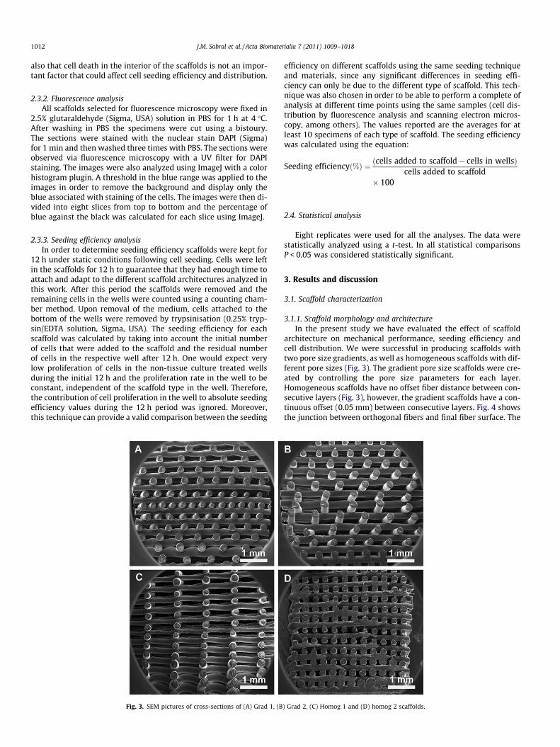
Fig. 3. SEM pictures of cross-sections of (A) Grad 1, (B
efficiency on different scaffolds using the same seeding techniqueand materials, since any significant differences in seeding effi-ciency can only be due to the different type of scaffold. This tech-nique was also chosen in order to be able to perform a complete ofanalysis at different time points using the same samples (cell dis-tribution by fluorescence analysis and scanning electron micros-copy, among others). The values reported are the averages for atleast 10 specimens of each type of scaffold. The seeding efficiencywas calculated using the equation:
Seeding efficiencyð%Þ ¼ ðcells added to scaffold� cells in wellsÞcells added to scaffold
� 100
2.4. Statistical analysis
Eight replicates were used for all the analyses. The data werestatistically analyzed using a t-test. In all statistical comparisonsP < 0.05 was considered statistically significant.
3. Results and discussion
3.1. Scaffold characterization
3.1.1. Scaffold morphology and architectureIn the present study we have evaluated the effect of scaffold
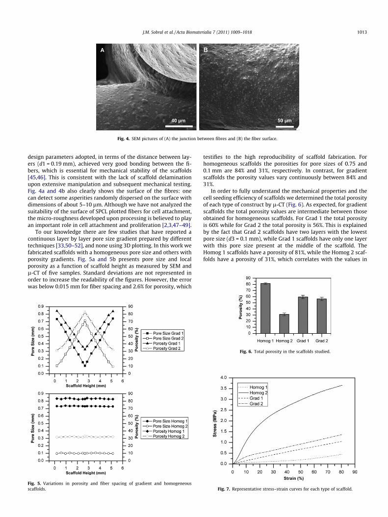
architecture on mechanical performance, seeding efficiency andcell distribution. We were successful in producing scaffolds withtwo pore size gradients, as well as homogeneous scaffolds with dif-ferent pore sizes (Fig. 3). The gradient pore size scaffolds were cre-ated by controlling the pore size parameters for each layer.Homogeneous scaffolds have no offset fiber distance between con-secutive layers (Fig. 3), however, the gradient scaffolds have a con-tinuous offset (0.05 mm) between consecutive layers. Fig. 4 showsthe junction between orthogonal fibers and final fiber surface. The
) Grad 2, (C) Homog 1 and (D) homog 2 scaffolds.
Fig. 4. SEM pictures of (A) the junction between fibres and (B) the fiber surface.
design parameters adopted, in terms of the distance between lay-ers (d1 = 0.19 mm), achieved very good bonding between the fi-bers, which is essential for mechanical stability of the scaffolds[45,46]. This is consistent with the lack of scaffold delaminationupon extensive manipulation and subsequent mechanical testing.Fig. 4a and 4b also clearly shows the surface of the fibres: onecan detect some asperities randomly dispersed on the surface withdimensions of about 5–10 lm. Although we have not analyzed thesuitability of the surface of SPCL plotted fibers for cell attachment,the micro-roughness developed upon processing is believed to playan important role in cell attachment and proliferation [2,3,47–49].
To our knowledge there are few studies that have reported acontinuous layer by layer pore size gradient prepared by differenttechniques [33,50–52], and none using 3D plotting. In this work wefabricated scaffolds with a homogeneous pore size and others withporosity gradients. Fig. 5a and 5b presents pore size and localporosity as a function of scaffold height as measured by SEM andl-CT of five samples. Standard deviations are not represented inorder to increase the readability of the figures. However, the errorwas below 0.015 mm for fiber spacing and 2.6% for porosity, which
Fig. 5. Variations in porosity and fiber spacing of gradient and homogeneousscaffolds.
testifies to the high reproducibility of scaffold fabrication. Forhomogeneous scaffolds the porosities for pore sizes of 0.75 and0.1 mm are 84% and 31%, respectively. In contrast, for gradientscaffolds the porosity values vary continuously between 84% and31%.
In order to fully understand the mechanical properties and thecell seeding efficiency of scaffolds we determined the total porosityof each type of construct by l-CT (Fig. 6). As expected, for gradientscaffolds the total porosity values are intermediate between thoseobtained for homogeneous scaffolds. For Grad 1 the total porosityis 60% while for Grad 2 the total porosity is 56%. This is explainedby the fact that Grad 2 scaffolds have two layers with the lowestpore size (d3 = 0.1 mm), while Grad 1 scaffolds have only one layerwith this pore size present at the middle of the scaffold. TheHomog 1 scaffolds have a porosity of 81%, while the Homog 2 scaf-folds have a porosity of 31%, which correlates with the values in
Fig. 7. Representative stress–strain curves for each type of scaffold.
previous studies using similar types of scaffolds and similar fabri-cation techniques [16,26,30,31].
3.1.2. Mechanical analysisCharacterization of the compressive characteristics of the scaf-
folds is important in many tissue engineering applications [53].Fig. 7 shows the stress and strain curves obtained for all samplesat 37 C. There is a clear difference in the energy absorption upondeformation between scaffolds up to 80% strain (see Fig. 7). Whencomparing the results presented in Fig. 7 with those in Fig. 8a it isevident that gradient scaffolds have intermediate mechanical per-formance compared with homogeneous scaffolds, indicating theexpected relationship between porosity of the scaffolds and therespective mechanical properties. Nevertheless, this correlation isnot linear, as the relative difference in porosity between the Grad1/Grad 2 and Homog 2 scaffolds does not on its own account forthe differences in stiffness. This may be attributed to other factors,such as the orientation and relative positioning of the fibers alongthe scaffold, which can play a key role in determining the finalmechanical performance [26,54–56]. A starch–polycaprolactone(30/70 wt.%) material has been shown to have a Young’s modulusof approximately 400 MPa. However, these values may vary con-siderably depending the on temperature and humidity (from 100to 800 MPa) [57,58]. Moreover, when considering scaffolds withhigh porosities tested under physiological conditions the Young’smodulus can decrease to 0.8–30 MPa [59]. The values reportedhere correlate with those found in the literature for 3D scaffoldsbased on starch [60].
Scaffold resilience upon creep deformation is very important intissue engineering applications [53]. Fig. 8b shows that the archi-tecture of a scaffold influences its resilience. The gradient scaffoldsrecovered approximately 77% of their initial height after a defor-mation of 60%, while the homogeneous scaffolds Homog 1 and
Fig. 9. Variations in (A) E0 and (B) tan d with frequ
Fig. 8. Values of (A) Young’s modulus and (B) percentage reco
Homog 2 recovered 87% and 67% of their initial height, respec-tively. The total porosity of the scaffolds can once more be relatedto these values. It is known that the modulus of interconnectedporous materials is dependent on their relative density, i.e. the in-verse of porosity. This is evident from the greater stiffness ofHomog 2 compared with the more porous architectures producedhere. The Gibson and Ashby model for the compression of open cellelastic foams shows that upon continuous compression buckling ofthe structure will ultimately occur at a given collapse stress that isproportional to the material density. Although such a model is notdirectly related to our case, the basic fundamentals are still usefulin explaining the different resilience values reported for the differ-ent scaffold architectures. For a given compression deformationapplied during creep testing a higher stress is imposed on Homog2 scaffolds, due to its greater stiffness, compared with the Grad 1,Grad 2 and Homog 1 scaffolds. Therefore, for the same imposeddeformation the higher stress applied to Homog 2 scaffolds causesmore extensive collapse of the structure. These results indicatethat despite stiffness being a parameter that needs to be consid-ered in the design of new scaffolds for biomedical applications itcan negatively affect the ability of a scaffold to recover after defor-mation. One could argue that the ability of a scaffold to avoid plas-tic deformation, remaining in an elastic state, and being able torecover can be as important as stiffness in the design of materialsand scaffold architectures for biomedical applications.
The viscoelastic properties of a polymer determine the mechan-ical behavior when used as an implanted biomaterial. It has previ-ously been shown that DMA is able to characterize the viscoelasticproperties of starch-based biomaterials [61–63], the mechanicalresponses of which are highly dependent on the hydration level[64,65]. DMA was used in this work to characterize the viscoelasticproperties of the SPCL 3D scaffolds under wet conditions. Thedependence of the storage modulus (E0) and frequency loss factor
ency for the scaffolds studied at 37 �C in PBS.
very for the scaffolds studied after a deformation of 80%.
Fig. 10. Seeding efficiency for each type of scaffold. *Statistical significance (t-test,P < 0.05) in gradient scaffolds. #Statistical significance (t-test, P < 0.05) in homoge-neous scaffolds.
(tan d) at 37 �C in PBS solution are presented in Fig. 9. Essentially, aslight increase in E0 and decrease in tan d is detected for SPCL withan increase in frequency in the range analyzed (0.1 and 16 Hz).tan d is a measure of the damping capability of the material andis related to the relative weight of the viscous and elastic featuresof the material and is not directly linked to porosity. Therefore, thetrends in tan d among the different structures are not the same asobserved for the Young’s modulus and elastic modulus, which arestrongly dependent on porosity and scaffold internal architecture.Fig. 9 also shows that the values of tan d at body temperature werebetween 0.09 and 0.15, which is a narrow range for this type oftest. These values are in agreement with those previously reportedfor this material [66–68] and indicate that SPCL is able to dissipatea significant fraction of the imposed mechanical energy. It wouldalso be interesting to compare the obtained values of tan d withthose found in native tissues. Other studies have shown that tan dvalues for biological tissues like bone are of the same order of mag-nitude as the values of tan d reported here [69]. Fig. 9b indicatesthat the structures with a gradient morphology have slightly high-er tan d values than the homogeneous ones, but the differences ob-served between these two kinds of scaffolds are unclear and any
Fig. 11. Images taken with a florescence microscope of cross-secti
discussion at this stage would be speculative. Regarding E0, the val-ues from DMA are very similar to those obtained under quasi-statictesting, and the same relationships to porosity and pore architec-ture are again observed.
3.2. Biological performance of the scaffolds
3.2.1. Seeding efficiency and distribution of cellsTo evaluate cell response to the scaffold architecture the con-
structs were cultured in vitro for 12 h, after which all experimentswere conducted. As was mentioned before, seeding efficiency playsa major role in tissue engineering approaches and is mainly af-fected by the scaffold material and the respective porous architec-ture. Fig. 10 shows the seeding efficiency for each scaffold type. Theseeding efficiencies of Grad 1 and Grad 2 were approximately 70%and 56%, respectively. For the homogeneous scaffolds Homog 1 andHomog 2 the seeding efficiencies were approximately 30% and 40%,respectively, which correlates with the values in the literature[18,27]. The results indicate that in the gradient scaffolds, espe-cially Grad 1, there was a significant improvement in seeding effi-ciency. Although seeding efficiency has been associated with thesurface area available for cells to attach to, recent studies haveshown that in RP scaffolds the pore structure and scaffold architec-ture can play a more important role [31,70]. The pore structure dic-tates the interaction of the scaffold and transplanted cells with thehost tissue. As is known, only scaffolds having an interconnectedporous structure are able to allow free bulk transport of biomole-cules, and in scaffolds with large enough pores (d > 10 lm) cellsare also able to migrate through them [71]. For instance, for bonein-growth [72] the minimum pore size for cell migration and nutri-ent diffusion is considered to be around 100 lm. However, poresizes above 300 lm are recommended to promote new bone for-mation and tissue vascularization. In addition, it is also known that3D matrices with similar porosities but different pore geometries,such as fibrous versus spherical pores, can yield different masstransport profiles and thus differently influence cell behavior[6,73]. Therefore, the differences in cell seeding efficiency observedbetween the Grad 1 and Grad 2 scaffolds (with similar surfaceareas) and between the gradient scaffolds and Homog 2 (with amuch higher surface area) can only be explained by the differencesin scaffold architecture.
ons of (A) Grad 1 and (B) Grad 2 scaffolds stained with DAPI.
Fig. 12. Images taken with a florescence microscope of cross-sections of (A) Homog 1 and (B) Homog 2 scaffolds stained with DAPI.
The difference between the Homog 1 and Homog 2 scaffolds canbe attributed to a higher surface area for the Homog 2 scaffold, whichallows the adhesion of more cells to the top and lower layers. In addi-tion, the higher structural density of the Homog 2 scaffolds arisingfrom the higher number of junction sites between orthogonal fibresalso contributes to an increased cell seeding efficiency. The exis-tence of more junction points should be related to better anchorageof cells to the scaffolds, increasing the chances of cell adhesion uponseeding. With regard to the differences between the gradient andhomogeneous scaffolds, the increase in seeding efficiency can be ex-plained by the presence of an offset between consecutive layers inthe gradient scaffolds [12,26,27]. However, the existence of a geo-metrical offset does not explain the absolute cell seeding efficiencynor the relative difference between the Grad 1 and Grad 2 scaffolds,as both have an offset. We believe that cell seeding efficiency is influ-enced by both the offset of consecutive scaffold layers and the flowconditions throughout the scaffold during cell seeding. The flowconditions when pipetting a cell suspension onto the scaffold resem-ble the flow under dynamic seeding [74,75]. A low flow rate within
Fig. 13. Images showing (A) an example of a cross-section of scaffold Grad 1 cutinto eight slices and filtered to show only the blue associated with the cell stainingand (B) variation in the amount of blue in the scaffold slices from the top to thebottom.
the scaffold upon seeding favors cell attachment at the fiber surfaceand junction sites, while high flow rates promote cell deposition atthe bottom of the well. In addition, the existence of an offset or acomplex pore shape can also enhance the average flow path of med-ium within the scaffold upon seeding, which also favors seeding effi-ciency. Thus, the flow will probably be conditioned by the size of thepores and the scaffold architecture. Figs. 11–13 show the cell distri-bution with height in the scaffolds. The results show that the distri-bution of cells is more homogeneous in Grad 1 scaffolds and in bothgradient scaffolds compared with the homogeneous ones. Theexplanation for this might also be related to that given for the highercell seeding efficiencies in the gradient scaffolds. The flow mechan-ics can probably explain why the cell distribution in Grad 1 (Figs. 11aand 13) is more homogeneous than in Grad 2 (Figs. 11b and 13). InGrad 1 scaffolds there is a decrease in pore size from the initial layerto the middle of the scaffold, which constrains flow through the scaf-fold. This, combined with the offset of the fibers favors cell seeding.In Grad 2 cells tend to become entrapped only in the final layers nearthe bottom of the well, due to the final decrease in pore size. The pos-sibility that the seeding technique used might contribute to anasymmetric distribution of cells within the scaffolds (e.g. a tendencyfor cells to attach more to the bottom and top layers of the scaffolds)and that the same effect would not be observed using a differentseeding technique (e.g. dynamic seeding with spinning flasks) can-not be ruled out. However, the observation that cell distributioncan be controlled by the internal architecture of a 3D scaffold andthat there is a more homogeneous cell distribution in the gradientscaffolds produced in this work remains valid for the seeding tech-nique used. For homogeneous scaffolds (Figs. 12 and 13) the resultsin terms of cell seeding efficiency and cell distribution are not asgood. These scaffolds do not possess any offset and so the cells tendto fall to the bottom of the scaffold, where they mostly attach. Wealso assume that in both homogeneous scaffolds the flow of mediumwhen adding a cell solution is greater than in the gradient scaffolds,due to the nonexistence of offset layers.
4. Conclusions
Application of RP techniques to the production of anatomicallyadapted bone tissue engineering scaffolds is the only method avail-able that can create predetermined forms and internal architec-
tures. This work has shown that manipulation of the mechanicalproperties and some biological parameters can be achieved byoptimizing such architectures. Furthermore, starch-based scaffoldscould be produced with predefined pore size gradients by a singlestep fabrication process. In this context, the architecture of a scaf-fold determines not only the physical properties, but also the cellseeding efficiency and cell distribution within the scaffold. Thedevelopment of continuous pore size gradients is able to improvecell seeding efficiency and induce a more uniform distribution ofcells through the scaffold.
Acknowledgement
This work was supported by the European NoE EXPERTISSUES(NMP3-CT-2004-500283).
Appendix A
Figures with essential colour discrimination. Certain figures inthis article, particularly Figs. 11–13, are difficult to interpret inblack and white. The full colour images can be found in the on-lineversion, at doi:.10.1016/j.actbio.2010.11.003.
References
[1] Langer R, Vacanti JP. Tissue engineering. Science 1993;260:920–6.[2] Flemming RG et al. Effects of synthetic micro- and nano-structured surfaces on
Med Eng Phys 2000;22:595–606.[4] Andersson H, Van den Berg A. Microfabrication and microfluidics for tissue
engineering: state of the art and future opportunities. Lab Chip2004;4:98–103.
[5] Yeong WY et al. Rapid prototyping in tissue engineering: challenges andpotential. Trends Biotechnol 2004;22:643–52.
[6] Lee J et al. Three-dimensional cell culture matrices: state of the art. Tissue EngPart B Rev 2008;14:61–86.
[7] Hutmacher DW et al. Scaffold-based tissue engineering: Rationale forcomputer-aided design and solid free-form fabrication systems. TrendsBiotechnol 2004;22:354–62.
[8] Hutmacher DW, Cool S. Concepts of scaffold-based tissue engineering–therationale to use solid free-form fabrication techniques. J Cell Mol Med2007;11:654–69.
[9] Hutmacher DW. Scaffolds in tissue engineering bone, cartilage. Biomaterials2000;21:2529–43.
[10] Zein I et al. Fused deposition modeling of novel scaffold architectures for tissueengineering applications. Biomaterials 2002;23:1169–85.
[11] Leong KF et al. Solid freeform fabrication of three-dimensional scaffolds forengineering replacement tissues and organs. Biomaterials 2003;24:2363–78.
[12] Woodfield TBF et al. Design of porous scaffolds for cartilage tissue engineeringusing a three-dimensional fiber-deposition technique. Biomaterials2004;25:4149–61.
[13] Malda J et al. The effect of PEGT/PBT scaffold architecture on the compositionof tissue engineered cartilage. Biomaterials 2005;26:63–72.
[14] Miot S et al. Effects of scaffold composition and architecture on human nasalchondrocyte redifferentiation and cartilaginous matrix deposition.Biomaterials 2005;26:2479–89.
[15] Moroni L et al. 3D fiber-deposited scaffolds for tissue engineering: Influence ofpores geometry and architecture on dynamic mechanical properties.Biomaterials 2006;27:974–85.
[16] Yousefi AM et al. Design and fabrication of 3D-plotted polymeric scaffolds infunctional tissue engineering. Polym Eng Sci 2007;47:608–18.
[17] Fedorovich NE et al. Three-dimensional fiber deposition of cell-laden, viable,patterned constructs for bone tissue printing. Tissue Eng Part A2008;14:127–33.
[18] Pfister A et al. Biofunctional rapid prototyping for tissue-engineeringapplications: 3D bioplotting versus 3D printing. J Polym Sci Part A: PolymChem 2004;42:624–38.
[19] Kim BS et al. Optimizing seeding and culture methods to engineer smoothmuscle tissue on biodegradable polymer matrices. Biotechnol Bioeng1998;57:46–54.
[20] Carrier RL et al. Cardiac tissue engineering: cell seeding, cultivationparameters, and tissue construct characterization. Biotechnol Bioeng1999;64:580–9.
[21] Xiao YL et al. Static and dynamic fibroblast seeding and cultivation in porousPEO/PBT scaffolds. J Mater Sci: Mater Med 1999;10:773–7.
[22] Holy CE et al. Engineering three-dimensional bone tissue in vitro usingbiodegradable scaffolds: investigating initial cell-seeding density and cultureperiod. J Biomed Mater Res 2000;51:376–82.
[23] Li Y et al. Effects of filtration seeding on cell density, spatial distribution, andproliferation in nonwoven fibrous matrices. Biotechnol Prog 2001;17:935–44.
[24] Vunjak-Novakovic G, Radisic M. Cell seeding of polymer scaffolds. MethodsMol Biol 2004;238:131–46.
[25] Galban CJ, Locke BR. Effects of spatial variation of cells, nutrient, productconcentrations coupled with product inhibition on cell growth in a polymerscaffold. Biotechnol Bioeng 1999;64:633–43.
[26] Yilgor P et al. 3D plotted PCL scaffolds for stem cell based bone tissueengineering. Macromol Symp 2008;269:92–9.
[27] El-Ayoubi R et al. Design and fabrication of 3D porous scaffolds to facilitatecell-based gene therapy. Tissue Eng Part A 2008;14:1037–48.
[28] Li JP et al. Bone ingrowth in porous titanium implants produced by 3D fiberdeposition. Biomaterials 2007;28:2810–20.
[29] Moroni L et al. Anatomical 3D fiber-deposited scaffolds for tissue engineering:designing a neotrachea. Tissue Eng 2007;13:2483–93.
[30] Detsch R et al. 3D-cultivation of bone marrow stromal cells on hydroxyapatitescaffolds fabricated by dispense-plotting and negative mould technique. JMater Sci: Mater Med 2008;19:1491–6.
[31] Moroni L., et al. 3D fiber-deposited electrospun integrated scaffolds enhancecartilage tissue formation. Adv Funct Mater. 2008;18 11:53–60.
[32] Woodfield TBF et al. Polymer scaffolds fabricated with pore-size gradients as amodel for studying the zonal organization within tissue-engineered cartilageconstructs. Tissue Eng 2005;11:1297–311.
[33] Harley BA et al. Fabricating tubular scaffolds with a radial pore size gradient bya spinning technique. Biomaterials 2006;27:866–74.
[34] Silva MMCG et al. The effect of anisotropic architecture on cell and tissueinfiltration into tissue engineering scaffolds. Biomaterials 2006;27:5909–17.
[35] Oh SH et al. In vitro and in vivo characteristics of PCL scaffolds with pore sizegradient fabricated by a centrifugation method. Biomaterials2007;28:1664–71.
[36] Kim G et al. Hybrid process for fabricating 3D hierarchical scaffolds combiningrapid prototyping and electrospinning. Macromol Rapid Commun2008;29:1577–81.
[37] Martins A et al. Hierarchical starch-based fibrous scaffold for bone tissueengineering applications. J Tissue Eng Regener Med 2009;3:37–42.
[38] Kubo K et al. Cellular behavior on TiO2 nanonodular structures in a micro-to-nanoscale hierarchy model. Biomaterials 2009;30:5319–29.
[39] Park S et al. 3D polycaprolactone scaffolds with controlled pore structure usinga rapid prototyping system. J Mater Sci: Mater Med 2009;20:229–34.
[40] Marques AP et al. Effect of starch-based biomaterials on the in vitroproliferation and viability of osteoblast-like cells. J Mater Sci: Mater Med2005;16:833–42.
[41] Li WJ et al. Biological response of chondrocytes cultured in three-dimensionalnanofibrous poly(epsilon-caprolactone) scaffolds. J Biomed Mater Res, Part A2003;67:1105–14.
[42] Alves CM et al. The dynamics, kinetics and reversibility of protein adsorptiononto the surface of biodegradable materials. Soft Matter 2010;6:4135–43.
[43] Marques AP et al. An in vivo study of the host response to starch-basedpolymers and composites subcutaneously implanted in rats. Macromol Biosci2005;5:775–85.
[44] Vehof JWM et al. Bone formation in CaP-coated and noncoated titanium fibermesh. J Biomed Mater Res, Part A 2003;64:417–26.
[45] Landers R, Mulhaupt R. Desktop manufacturing of complex objects, prototypesand biomedical scaffolds by means of computer-assisted design combinedwith computer-guided 3D plotting of polymers and reactive oligomers.Macromol Mater Eng 2000;282:17–21.
[46] Landers R et al. Rapid prototyping of scaffolds derived from thermoreversiblehydrogels and tailored for applications in tissue engineering. Biomaterials2002;23:4437–47.
[47] Meyle J et al. Fibroblast anchorage to microtextured surfaces. J Biomed MaterRes 1993;27:1553–7.
[48] Liu XM et al. Influence of substratum surface chemistry/energy andtopography on the human fetal osteoblastic cell line hFOB 1.19: phenotypicand genotypic responses observed in vitro. Biomaterials 2007;28:4535–50.
[49] Marcotte L, Tabrizian A. Sensing Surfaces: challenges in studying the celladhesion process and the cell adhesion forces on biomaterials. IRBM2008;29:77–88.
[50] Bretcanu O et al. Simple methods to fabricate Bioglass (R)-derived glass-ceramic scaffolds exhibiting porosity gradient. J Mater Sci 2008;43:4127–34.
[51] Tamayo A et al. Gradient pore size distributions in porous silicon oxycarbidematerials. J Eur Ceram Soc 2008;28:1871–9.
[52] Wu H et al. Fabrication of chitosan–g-polycaprolactone copolymer scaffoldswith gradient porous microstructures. Mater Lett 2008;62:2733–6.
[53] Alves NM et al. Microhardness of starch based biomaterials in simulatedphysiological conditions. Acta Biomater 2007;3:69–76.
[54] Hutmacher DW et al. Mechanical properties and cell cultural response ofpolycaprolactone scaffolds designed and fabricated via fused depositionmodeling. J Biomed Mater Res 2001;55:203–16.
[55] Guarino V et al. Porosity and mechanical properties relationship in PCL porousscaffolds. J Appl Biomater Biomech 2007;5:149–57.
[56] Yu H et al. Effect of porosity and pore size on microstructures and mechanicalproperties of poly-epsilon-caprolactone–hydroxyapatite composites. J BiomedMater Res B Appl Biomater 2008;86:541–7.
[57] Sen A et al. Creep in injection molded starch/synthetic polymer blends. MaterSci Eng, A 2002;338:60–9.
[58] Odusanya OS et al. Effect of starch predrying on the mechanical properties ofstarch/poly(epsilon-caprolactone) composites. J Appl Polym Sci2003;87:877–84.
[59] Preechawong D et al. Characterization of starch/poly(epsilon-caprolactone)hybrid foams. Polym Test 2004;23:651–7.
[60] Gomes ME et al. Starch–poly(epsilon-caprolactone) and starch–poly(lacticacid) fibre-mesh scaffolds for bone tissue engineering applications: structure,Mechanical properties and degradation behaviour. J Tissue Eng Regener Med2008;2:243–52.
[61] Mano JF et al. Dynamic mechanical properties of hydroxyapatite-reinforcedand porous starch-based degradable biomaterials. J Mater Sci: Mater Med1999;10:857–62.
[62] Mano JF et al. Effects of moisture and degradation time over the mechanicaldynamical performance of starch-based biomaterials. J Appl Polym Sci2000;78:2345–57.
[63] Espigares I et al. New partially degradable and bioactive acrylic bone cementsbased on starch blends and ceramic fillers. Biomaterials 2002;23:1883–95.
[64] Mano JF, Reis RL. Viscoelastic monitoring of starch-based biomaterials insimulated physiological conditions. Mater Sci Eng, A 2004;370:321–5.
[65] Ghosh S et al. Dynamic mechanical behavior of starch-based scaffolds in dryand physiologically simulated conditions: effect of porosity and pore size. ActaBiomater 2008;4:950–9.
[66] Sousa RA et al. Mechanical performance of starch based bioactive compositebiomaterials molded with preferred orientation. Polym Eng Sci2002;42:1032–45.
[67] Mano JF et al. Thermal properties of thermoplastic starch/synthetic polymerblends with potential biomedical applicability. J Mater Sci: Mater Med2003;14:127–35.
[68] Elvira C et al. Starch-based biodegradable hydrogels with potential biomedicalapplications as drug delivery systems. Biomaterials 2002;23:1955–66.
[69] Buechner PM et al. A broadband viscoelastic spectroscopic study of bovinebone: implications for fluid flow. Ann Biomed Eng 2001;29:719–28.
[70] Hsu SH et al. Evaluation of the growth of chondrocytes and osteoblasts seededinto precision scaffolds fabricated by fused deposition manufacturing. JBiomed Mater Res B Appl Biomater 2007;80:519–27.
[71] Mooney DJ, Langer RS. Engineering biomaterials for tissue engineering The 10–100 micron size scale. In: Bronzino JD, editor. The biomedical engineeringhandbook. Boca Raton, FL: CRC Press; 2000.
[72] Karageorgiou V, Kaplan D. Porosity of 3D biomaterial scaffolds andosteogenesis. Biomaterials 2005;26:5474–91.
[73] Uebersax L et al. Effect of scaffold design on bone morphology in vitro. TissueEng 2006;12:3417–29.
[74] Wendt D et al. Oscillating perfusion of cell suspensions through three-dimensional scaffolds enhances cell seeding efficiency and uniformity.Biotechnol Bioeng 2003;84:205–14.
[75] Du DJ et al. Oscillatory perfusion seeding and culturing of osteoblast-like cellson porous beta-tricalcium phosphate scaffolds. J Biomed Mater Res, Part A2008;86:796–803.


![Phase separation in confined systems - Penn Engineeringbiophys/cv_files/reprint_rop...controlled pore glass (CPG) and the related Vycor glasses [128] have pore cross sections that](https://static.documents.pub/doc/80x56/60beeeb2507dc0543a74c159/phase-separation-in-conined-systems-penn-engineering-biophyscvfilesreprintrop.jpg)