3D Sensor planning framework for leaf probing Sergi Foix, Guillem Aleny` a and Carme Torras Abstract— Modern plant phenotyping requires active sensing technologies and particular exploration strategies. This article proposes a new method for actively exploring a 3D region of space with the aim of localizing special areas of interest for manipulation tasks over plants. In our method, exploration is guided by a multi-layer occupancy grid map. This map, together with a multiple-view estimator and a maximum- information-gain gathering approach, incrementally provides a better understanding of the scene until a task termination criterion is reached. This approach is designed to be applicable for any task entailing 3D object exploration where some previous knowledge of its general shape is available. Its suitability is demonstrated here for an eye-in-hand arm configuration in a leaf probing application. I. I NTRODUCTION Plant phenotyping studies the influence of environmental factors on the observable traits of plants. The success of such studies depends on the data extracted from a series of long-term monitoring experiments over a great number of plants under multiple environmental conditions. Measures can be obtained in two different scenarios. The first one includes regular fields and mobile sensors, either mounted on aerial vehicles using remote sensing techniques [1], or on ground robots [2]. Obviously, climate conditions can not be controlled here. The second one uses greenhouses, where variables like temperature, humidity, and light, can be controlled. The common setup includes large greenhouses with several isolated zones, and conveyor belts that carry each plant from its sitting position to a measure chamber where a rich set of sensors takes measurements before return- ing them [3]. The throughput obtained in such installations is considerably high. However, sensors in the measuring chamber are in a pre-defined position, and measurements are sometimes obtained from an inadequate point of view. Additionally, one of the main limitations is the difficulty to measure or perform actions that require contact with the plant, such as chlorophyll measurement or the extraction of disk samples for DNA analysis [4]. Therefore, a major step forward is to provide the system with the ability to move its perceptual unit, so that it can nat- urally adapt to the characteristics of each plant. In this paper a robotic system is proposed to overcome this weakness, that involves a time-of-flight camera (ToF) and a probing tool mounted on the end-effector of a robot manipulator. The approach includes three steps: (i) selection of the target leaf from a plant, (ii) exploration of this leaf to gather enough The authors are with the Institut de Rob` otica i Inform` atica Indus- trial, CSIC-UPC, Llorens i Artigas 4-6, 08028 Barcelona, Spain, {sfoix, galenya, torras}@iri.upc.edu. (a) Experimental setup (b) Leaf probing action Fig. 1: (a) Overall view of the complete setup, with the robot carrying the ToF camera and the tool, and the Kinect camera. (b) Observe that the leaf probing task requires the clearance (above and below) of a sector of the leaf. information, and (iii) effective execution of probing. The first step is usually specified by a botanical expert that defines a criterion to choose the leaf, for example the biggest one, or the i-th leaf from the stem. The last step, the measuring action, has been already presented in previous works [4]. This paper focuses on a method for solving the second step. We propose to perform task-driven exploration, that is gathering the necessary information to execute a task, with a method where the task is encoded in a combination of 3D occupancy grid maps. Although we concentrate on spatial restrictions like clearance, it is also shown that other task constraints, like veins and yellow spots that have to be avoided, can be represented in additional occupancy grid maps following the same idea. The goal of task-driven exploration is to move the robot through a sequence of views that will contribute to maximising the information for solving the task. We propose an algorithm that uses an information- gain approach to compute the expected benefit of each new possible view, and combines it with other aspects, such as the proximity to the current view, to obtain the best next view at each iteration. Observe that this is a local approach, and that it cannot be optimal since the next position of the sensor only depends on the available information at each iteration. An optimal solution would require a complete model of the plant beforehand. That is not feasible in plant phenotyping, since plants from the same species are quite different and even the same plant changes largely over time. The rest of the paper is organized as follows. Related works are discussed in Section II. In Section III, our leaf probing exploration framework is explained. Experimental results are presented and discussed in Section IV. Finally Section V is devoted to conclusions.
Transcript
3D Sensor planning framework for leaf probing
Sergi Foix, Guillem Alenya and Carme Torras
Abstract—Modern plant phenotyping requires active sensingtechnologies and particular exploration strategies. This articleproposes a new method for actively exploring a 3D region ofspace with the aim of localizing special areas of interest formanipulation tasks over plants. In our method, explorationis guided by a multi-layer occupancy grid map. This map,together with a multiple-view estimator and a maximum-information-gain gathering approach, incrementally providesa better understanding of the scene until a task terminationcriterion is reached.
This approach is designed to be applicable for any taskentailing 3D object exploration where some previous knowledgeof its general shape is available. Its suitability is demonstratedhere for an eye-in-hand arm configuration in a leaf probingapplication.
I. INTRODUCTION
Plant phenotyping studies the influence of environmental
factors on the observable traits of plants. The success of
such studies depends on the data extracted from a series
of long-term monitoring experiments over a great number
of plants under multiple environmental conditions. Measures
can be obtained in two different scenarios. The first one
includes regular fields and mobile sensors, either mounted
on aerial vehicles using remote sensing techniques [1], or
on ground robots [2]. Obviously, climate conditions can
not be controlled here. The second one uses greenhouses,
where variables like temperature, humidity, and light, can be
controlled. The common setup includes large greenhouses
with several isolated zones, and conveyor belts that carry
each plant from its sitting position to a measure chamber
where a rich set of sensors takes measurements before return-
ing them [3]. The throughput obtained in such installations
is considerably high. However, sensors in the measuring
chamber are in a pre-defined position, and measurements
are sometimes obtained from an inadequate point of view.
Additionally, one of the main limitations is the difficulty
to measure or perform actions that require contact with the
plant, such as chlorophyll measurement or the extraction of
disk samples for DNA analysis [4].
Therefore, a major step forward is to provide the system
with the ability to move its perceptual unit, so that it can nat-
urally adapt to the characteristics of each plant. In this paper
a robotic system is proposed to overcome this weakness,
that involves a time-of-flight camera (ToF) and a probing
tool mounted on the end-effector of a robot manipulator. The
approach includes three steps: (i) selection of the target leaf
from a plant, (ii) exploration of this leaf to gather enough
The authors are with the Institut de Robotica i Informatica Indus-trial, CSIC-UPC, Llorens i Artigas 4-6, 08028 Barcelona, Spain, {sfoix,galenya, torras}@iri.upc.edu.
(a) Experimental setup (b) Leaf probing action
Fig. 1: (a) Overall view of the complete setup, with the
robot carrying the ToF camera and the tool, and the Kinect
camera. (b) Observe that the leaf probing task requires the
clearance (above and below) of a sector of the leaf.
information, and (iii) effective execution of probing. The first
step is usually specified by a botanical expert that defines a
criterion to choose the leaf, for example the biggest one,
or the i-th leaf from the stem. The last step, the measuring
action, has been already presented in previous works [4].
This paper focuses on a method for solving the second step.
We propose to perform task-driven exploration, that is
gathering the necessary information to execute a task, with
a method where the task is encoded in a combination of 3D
occupancy grid maps. Although we concentrate on spatial
restrictions like clearance, it is also shown that other task
constraints, like veins and yellow spots that have to be
avoided, can be represented in additional occupancy grid
maps following the same idea. The goal of task-driven
exploration is to move the robot through a sequence of views
that will contribute to maximising the information for solving
the task. We propose an algorithm that uses an information-
gain approach to compute the expected benefit of each new
possible view, and combines it with other aspects, such as the
proximity to the current view, to obtain the best next view
at each iteration. Observe that this is a local approach, and
that it cannot be optimal since the next position of the sensor
only depends on the available information at each iteration.
An optimal solution would require a complete model of the
plant beforehand. That is not feasible in plant phenotyping,
since plants from the same species are quite different and
even the same plant changes largely over time.
The rest of the paper is organized as follows. Related
works are discussed in Section II. In Section III, our leaf
probing exploration framework is explained. Experimental
results are presented and discussed in Section IV. Finally
Section V is devoted to conclusions.
Fig. 2: 3D sensor planning framework.
II. RELATED WORK
The ability to move the sensor and consequently provide
a suitable view offers several advantages and it has been
investigated both in the field of mobile robotics and in the
field of active sensors mounted onto robot manipulators [5].
Regarding manipulators, active sensor planning algorithms
can be divided into two main groups depending on the
available initial information: model and non-model based.
Model-based methods require to have a previous complete
model of the object, usually a CAD model, and are useful for
industrial inspection or part localization. These approaches
are often based on visual servoing techniques [6]. Here,
planning algorithms find optimal solutions and consequently,
execute the minimum number of views to complete the task.
Non-model based methods assume vague knowledge about
the object. Using partial information the algorithm has to
produce a next-best-view (NBV) to incrementally gather new
data. This approach is commonly used for object model-
ing [7] and object recognition [8]. Necessarily, since NBV is
determined based on partial knowledge, an optimal solution
cannot be guaranteed. Our approach fits into this group.
Classical non-model based approaches rely on frontier-
based exploration. The camera is iteratively moved relative
to the closest or largest visible frontier, or among the two, to
the one with the easier configuration for the robot [9]. Their
implicit objective is the complete exploration of an area, it
being difficult to explicitly enforce a different task. These
methods are very adequate when using accurate sensing and
positioning devices [10], but not so much in the presence
of noise, since they do not handle uncertainty naturally. In
special cases though, where revisiting actions can be ensured,
the accumulated noise in the scene can be improved through
uncertainty reduction approaches [11].
Information gain is one of the most used measures for
candidate view selection. Each possible view, when visited,
provides a certain amount of new information. Even revisit-
ing already captured areas can provide newer information,
specially if observed from a different point of view. To
estimate the gain for each candidate view, some predictions
about the unexplored regions must be made. A typical
approach is to make assumptions about the nature of the
already captured surfaces. For instance, adjusting B-Splines
to sections of the 3D object [12], or modeling the surface as
a combination of a trend and some disturbances [13].
Note that, while a coarse model of a plant’s leaf can
be feasibly obtained for our application, it can not be
easily exploited by the current approaches. Instead, it has
been shown that 3D occupancy grid maps are well suited
for incremental object modeling [14], [15]. Therefore, we
propose a method that takes advantage of both a coarse
model of a leaf and 3D occupancy grid maps to graphically
encode the task of finding a good probing point.
III. LEAF PROBING FRAMEWORK
Neither leaf probing nor chlorophyll measurement requires
to have a complete leaf’s model to accomplish its goal.
Instead, only specific regions in the leaf’s contour are needed.
To specify the task, we consider two types of information:
the prior knowledge of the task and the on-line data, both
codified using probabilistic occupancy maps. This section
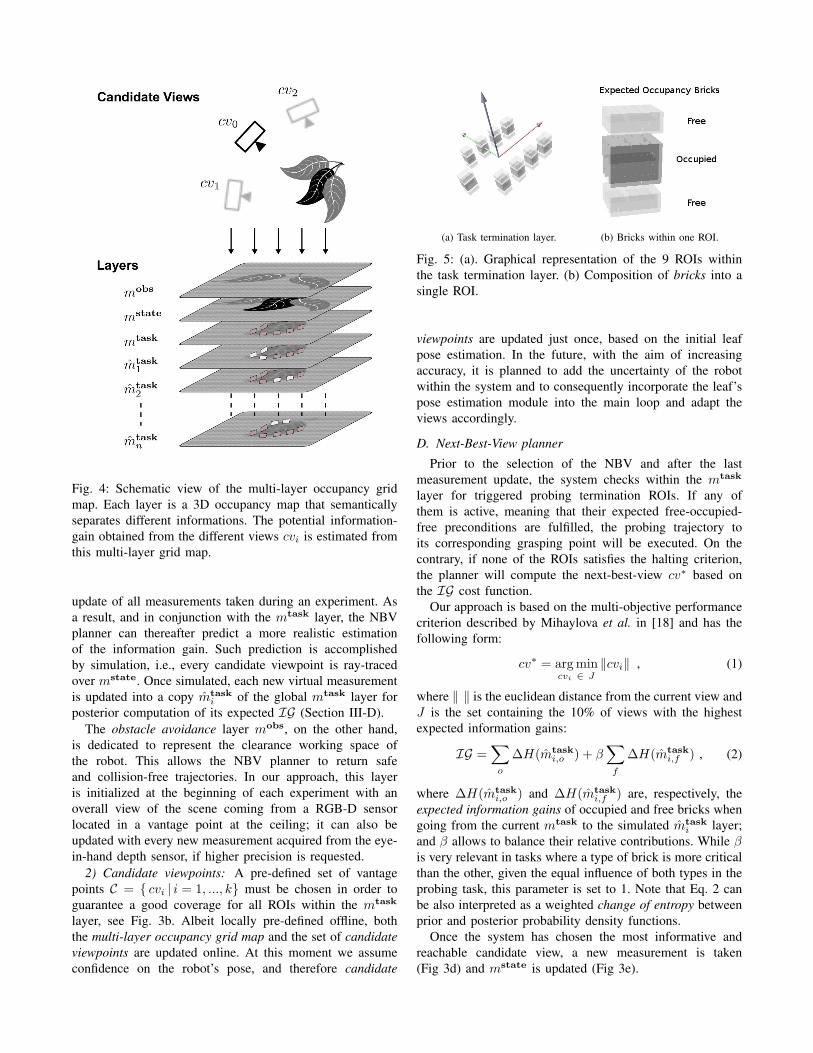
emphasises the following three main ideas:
1) All required data can be represented within a
multi-layer occupancy map, where each layer codi-
fies relevant information that is semantically differ-
ent (Sec. III-C.1). Particularly, the space occupied by
the leaf and the free space for allowing the tool to
reach the leaf.
2) The Information Gain (IG), used as a criterion to
evaluate potential new views, can be easily defined
and computed from the multi-layer representation
(Sec III-D). Its correct computation requires an accu-
rate model of the ToF camera (Sec. III-B).
3) The task termination criterion signals when enough
data is available to perform the task. Our representation
facilitates its definition and evaluation (Sec. III-C.1).
To easily understand the entire framework, we will first
describe the global set-up and thereafter its modules and how
they are interconnected. See Fig. 2 for an overall view of
the system. We stress again that our method focuses on the
main step of exploration planning between consecutive views
until task termination (ii), and not on the initial step of leaf
selection and pose estimation (i), nor on the final probing
Notes: Percentage of experiments that finished in a certain number ofviews. Some experiments resulted inconclusive due to external errorsin the path planner (5 in ¬obstacle exp. and 9 in the obstacle exp.)
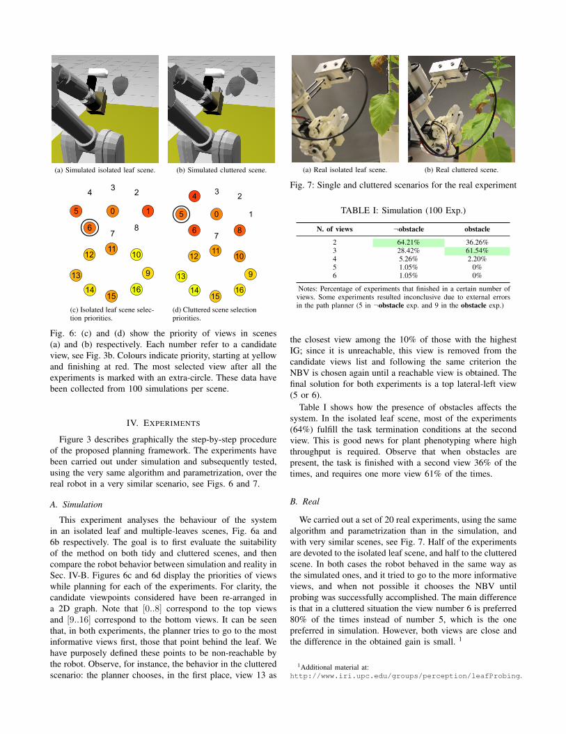
the closest view among the 10% of those with the highest
IG; since it is unreachable, this view is removed from the
candidate views list and following the same criterion the
NBV is chosen again until a reachable view is obtained. The
final solution for both experiments is a top lateral-left view
(5 or 6).
Table I shows how the presence of obstacles affects the
system. In the isolated leaf scene, most of the experiments
(64%) fulfill the task termination conditions at the second
view. This is good news for plant phenotyping where high
throughput is required. Observe that when obstacles are
present, the task is finished with a second view 36% of the
times, and requires one more view 61% of the times.
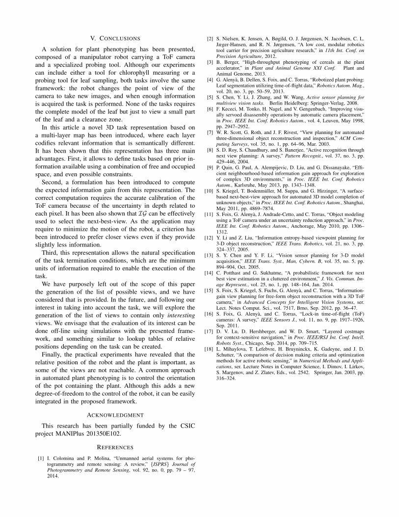
B. Real
We carried out a set of 20 real experiments, using the same
algorithm and parametrization than in the simulation, and
with very similar scenes, see Fig. 7. Half of the experiments
are devoted to the isolated leaf scene, and half to the cluttered
scene. In both cases the robot behaved in the same way as
the simulated ones, and it tried to go to the more informative
views, and when not possible it chooses the NBV until
probing was successfully accomplished. The main difference
is that in a cluttered situation the view number 6 is preferred
80% of the times instead of number 5, which is the one
preferred in simulation. However, both views are close and
the difference in the obtained gain is small. 1
1Additional material at:http://www.iri.upc.edu/groups/perception/leafProbing.
A solution for plant phenotyping has been presented,
composed of a manipulator robot carrying a ToF camera
and a specialized probing tool. Although our experiments
can include either a tool for chlorophyll measuring or a
probing tool for leaf sampling, both tasks involve the same
framework: the robot changes the point of view of the
camera to take new images, and when enough information
is acquired the task is performed. None of the tasks requires
the complete model of the leaf but just to view a small part
of the leaf and a clearance zone.
In this article a novel 3D task representation based on
a multi-layer map has been introduced, where each layer
codifies relevant information that is semantically different.
It has been shown that this representation has three main
advantages. First, it allows to define tasks based on prior in-
formation available using a combination of free and occupied
space, and even possible constraints.
Second, a formulation has been introduced to compute
the expected information gain from this representation. The
correct computation requires the accurate calibration of the
ToF camera because of the uncertainty in depth related to
each pixel. It has been also shown that IG can be effectively
used to select the next-best-view. As the application may
require to minimize the motion of the robot, a criterion has
been introduced to prefer closer views even if they provide
slightly less information.
Third, this representation allows the natural specification
of the task termination conditions, which are the minimum
units of information required to enable the execution of the
task.
We have purposely left out of the scope of this paper
the generation of the list of possible views, and we have
considered that is provided. In the future, and following our
interest in taking into account the task, we will explore the
generation of the list of views to contain only interesting
views. We envisage that the evaluation of its interest can be
done off-line using simulations with the presented frame-
work, and something similar to lookup tables of relative
positions depending on the task can be created.
Finally, the practical experiments have revealed that the
relative position of the robot and the plant is important, as
some of the views are not reachable. A common approach
in automated plant phenotyping is to control the orientation
of the pot containing the plant. Although this adds a new
degree-of-freedom to the control of the robot, it can be easily
integrated in the proposed framework.
ACKNOWLEDGMENT
This research has been partially funded by the CSIC
project MANIPlus 201350E102.
REFERENCES
[1] I. Colomina and P. Molina, “Unmanned aerial systems for pho-togrammetry and remote sensing: A review,” {ISPRS} Journal of
Photogrammetry and Remote Sensing, vol. 92, no. 0, pp. 79 – 97,2014.
[2] S. Nielsen, K. Jensen, A. Bøgild, O. J. Jørgensen, N. Jacobsen, C. L.Jæger-Hansen, and R. N. Jørgensen, “A low cost, modular roboticstool carrier for precision agriculture research,” in 11th Int. Conf. on
Precision Agriculture, 2012.[3] B. Berger, “High-throughput phenotyping of cereals at the plant
accelerator,” in Plant and Animal Genome XXI Conf. Plant andAnimal Genome, 2013.
[4] G. Alenya, B. Dellen, S. Foix, and C. Torras, “Robotized plant probing:Leaf segmentation utilizing time-of-flight data,” Robotics Autom. Mag.,vol. 20, no. 3, pp. 50–59, 2013.
[5] S. Chen, Y. Li, J. Zhang, and W. Wang, Active sensor planning for
multiview vision tasks. Berlin Heidelberg: Springer-Verlag, 2008.[6] F. Kececi, M. Tonko, H. Nagel, and V. Gengenbach, “Improving visu-
ally servoed disassembly operations by automatic camera placement,”in Proc. IEEE Int. Conf. Robotics Autom., vol. 4, Leuven, May 1998,pp. 2947–2952.
[7] W. R. Scott, G. Roth, and J. F. Rivest, “View planning for automatedthree-dimensional object reconstruction and inspection,” ACM Com-
puting Surveys, vol. 35, no. 1, pp. 64–96, Mar. 2003.[8] S. D. Roy, S. Chaudhury, and S. Banerjee, “Active recognition through
next view planning: A survey,” Pattern Recognit., vol. 37, no. 3, pp.429–446, 2004.
[9] P. Quin, G. Paul, A. Alempijevic, D. Liu, and G. Dissanayake, “Effi-cient neighbourhood-based information gain approach for explorationof complex 3D environments,” in Proc. IEEE Int. Conf. Robotics
Autom., Karlsruhe, May 2013, pp. 1343–1348.[10] S. Kriegel, T. Bodenmuller, M. Suppa, and G. Hirzinger, “A surface-
based next-best-view approach for automated 3D model completion ofunknown objects,” in Proc. IEEE Int. Conf. Robotics Autom., Shanghai,May 2011, pp. 4869–7874.
[11] S. Foix, G. Alenya, J. Andrade-Cetto, and C. Torras, “Object modelingusing a ToF camera under an uncertainty reduction approach,” in Proc.
IEEE Int. Conf. Robotics Autom., Anchorage, May 2010, pp. 1306–1312.
[12] Y. Li and Z. Liu, “Information entropy-based viewpoint planning for3-D object reconstruction,” IEEE Trans. Robotics, vol. 21, no. 3, pp.324–337, 2005.
[13] S. Y. Chen and Y. F. Li, “Vision sensor planning for 3-D modelacquisition,” IEEE Trans. Syst., Man, Cybern. B, vol. 35, no. 5, pp.894–904, Oct. 2005.
[14] C. Potthast and G. Sukhatme, “A probabilistic framework for nextbest view estimation in a cluttered environment,” J. Vis. Commun. Im-age Represent., vol. 25, no. 1, pp. 148–164, Jan. 2014.
[15] S. Foix, S. Kriegel, S. Fuchs, G. Alenya, and C. Torras, “Information-gain view planning for free-form object reconstruction with a 3D ToFcamera,” in Advanced Concepts for Intelligent Vision Systems, ser.Lect. Notes Comput. Sci., vol. 7517, Brno, Sep. 2012, pp. 36–47.
[16] S. Foix, G. Alenya, and C. Torras, “Lock-in time-of-flight (ToF)cameras: A survey,” IEEE Sensors J., vol. 11, no. 9, pp. 1917–1926,Sep. 2011.
[17] D. V. Lu, D. Hershberger, and W. D. Smart, “Layered costmapsfor context-sensitive navigation,” in Proc. IEEE/RSJ Int. Conf. Intell.
Robots Syst., Chicago, Sep. 2014, pp. 709–715.[18] L. Mihaylova, T. Lefebvre, H. Bruyninckx, K. Gadeyne, and J. D.
Schutter, “A comparison of decision making criteria and optimizationmethods for active robotic sensing,” in Numerical Methods and Appli-
cations, ser. Lecture Notes in Computer Science, I. Dimov, I. Lirkov,S. Margenov, and Z. Zlatev, Eds., vol. 2542. Springer, Jan. 2003, pp.316–324.