3D Vision Guided Robotic Charging Station for Electric and Plug-in Hybrid Vehicles Justinas Miˇ seikis 1 , Matthias R¨ uther 2 , Bernhard Walzel 3 , Mario Hirz 3 and Helmut Brunner 3 Abstract— Electric vehicles (EVs) and plug-in hybrid vehicles (PHEVs) are rapidly gaining popularity on our roads. Besides a comparatively high purchasing price, the main two problems limiting their use are the short driving range and inconvenient charging process. In this paper we address the following by presenting an automatic robot-based charging station with 3D vision guidance for plugging and unplugging the charger. First of all, the whole system concept consisting of a 3D vision system, an UR10 robot and a charging station is presented. Then we show the shape-based matching methods used to successfully identify and get the exact pose of the charging port. The same approach is used to calibrate the camera-robot system by using just known structure of the connector plug and no additional markers. Finally, a three-step robot motion planning procedure for plug-in is presented and functionality is demonstrated in a series of successful experiments. I. INTRODUCTION Nowadays it is common to see electric vehicles and plug-in hybrids on our roads. Worldwide plug-in vehicle sales in 2016 were 773600 units, 42% higher compared to 2015 [1]. For example Norway plans to rule out sales of any combustion engine cars by 2025 [4]. However, a new problem being faced by EV and PHEV drivers is having an accessible, fast and convenient battery charging, especially when traveling longer distances. It becomes a common problem of fast chargers being occupied even when the car has finished charging, but the owner has not come back yet. For example, Tesla has added an additional idle fee to discourage drivers leaving their cars at the chargers for longer than necessary [7]. A solution to avoid this problem and to enable a comfortable fast charging, would be an automated robot-based charging system combined with automated car parking. A. Charging Ports and Cables Worldwide, there are many types of EV and PHEV charging ports, as well as different charging port placement locations on the vehicle. Each one of them 1 Justinas Miˇ seikis is with Department of Informatics, University of Oslo, Oslo, Norway[email protected]2 Matthias R¨ uther is with Graz University of Technology, Institute for Computer Graphics and Vision, Graz, Austria [email protected]3 Bernhard Walzel, Mario Hirz and Helmut Brunner are with Graz University of Technology, Institute for Automotive Engineer- ing, Graz, Austria {bernhard.walzel, mario.hirz, helmut.brunner}@icg.tugraz.at has benefits and detriments, and car manufacturers have not decided on a common standard yet. This introduces an additional inconvenience of finding the correct type of charger, or having to carry a number of bulky adapters. As long as there is no standard, it would be more convenient to let the charging station detect the correct port type and adapt accordingly. Another issue is the current weight and stiffness of a quick charging cable. For example, the weight of a CCS-Type 2 charging cable rated for the power up to 200 kW is 2.26 kg/m and outer diameter of 32 mm. With longer cable lengths, this becomes difficult for people to handle, but would not be an issue for a robot [6]. Cooled charging cables can help to solve this problem by increasing the cable diameter, but these are not yet standard [17]. B. Existing Automated EV Charging Methods Automatic charging solutions have been researched both in academic and industrial environments. Volks- wagen have presented an e-smartConnect system, where a Kuka LBR-iiwa robot automatically plugs in the vehicle after it autonomously parks in a specific target area (allowing for less than 20 cm by 20 cm error). It is also limited to one charging port type [8]. Tesla have demonstrated a concept of a snake-like robot automatically plugging in their EV, however, no technical details on the charging port localisation or robot operation were revealed [9]. The Dortmund Technical University have presented a prototype of the automatic charging system called ALanE. It is based on a robot arm capable of auto- matically plugging and unplugging a standard energy supply to an electric vehicle. The system is controlled via smartphone. However, full capabilities and flexi- bility of this concept system are not clear [3]. The NRG-X concept presents itself as a fully automatic charging solution. It can be adapted to any EV or PHEV and is capable of fast charging. Furthermore, it has a tolerance for inaccurate parking positions. The NRG-X system is based on combination of conductive and inductive charging on the under- body of the vehicle, thus an adapter for the vehicle is necessary. Furthermore, the current concept configura- tion the charging power is limited to 22 kW [5], which results in over 7 times longer charging compared to 170 kW charging [22] and perspective 350kW [11]. arXiv:1703.05381v1 [cs.RO] 15 Mar 2017
Transcript
3D Vision Guided Robotic Charging Station for Electric andPlug-in Hybrid Vehicles
Justinas Miseikis1, Matthias Ruther2, Bernhard Walzel3, Mario Hirz3 and Helmut Brunner3
Abstract— Electric vehicles (EVs) and plug-in hybridvehicles (PHEVs) are rapidly gaining popularity on ourroads. Besides a comparatively high purchasing price,the main two problems limiting their use are the shortdriving range and inconvenient charging process. Inthis paper we address the following by presenting anautomatic robot-based charging station with 3D visionguidance for plugging and unplugging the charger. Firstof all, the whole system concept consisting of a 3Dvision system, an UR10 robot and a charging stationis presented. Then we show the shape-based matchingmethods used to successfully identify and get the exactpose of the charging port. The same approach is usedto calibrate the camera-robot system by using justknown structure of the connector plug and no additionalmarkers. Finally, a three-step robot motion planningprocedure for plug-in is presented and functionality isdemonstrated in a series of successful experiments.
I. INTRODUCTION
Nowadays it is common to see electric vehiclesand plug-in hybrids on our roads. Worldwide plug-invehicle sales in 2016 were 773600 units, 42% highercompared to 2015 [1]. For example Norway plansto rule out sales of any combustion engine cars by2025 [4]. However, a new problem being faced byEV and PHEV drivers is having an accessible, fast andconvenient battery charging, especially when travelinglonger distances. It becomes a common problem offast chargers being occupied even when the car hasfinished charging, but the owner has not come backyet. For example, Tesla has added an additional idlefee to discourage drivers leaving their cars at thechargers for longer than necessary [7]. A solution toavoid this problem and to enable a comfortable fastcharging, would be an automated robot-based chargingsystem combined with automated car parking.
A. Charging Ports and Cables
Worldwide, there are many types of EV and PHEVcharging ports, as well as different charging portplacement locations on the vehicle. Each one of them
1Justinas Miseikis is with Department of Informatics, Universityof Oslo, Oslo, [email protected]
2Matthias Ruther is with Graz University of Technology,Institute for Computer Graphics and Vision, Graz, [email protected]
3Bernhard Walzel, Mario Hirz and Helmut Brunner are withGraz University of Technology, Institute for Automotive Engineer-ing, Graz, Austria {bernhard.walzel, mario.hirz,helmut.brunner}@icg.tugraz.at
has benefits and detriments, and car manufacturershave not decided on a common standard yet. Thisintroduces an additional inconvenience of finding thecorrect type of charger, or having to carry a numberof bulky adapters. As long as there is no standard, itwould be more convenient to let the charging stationdetect the correct port type and adapt accordingly.
Another issue is the current weight and stiffness ofa quick charging cable. For example, the weight ofa CCS-Type 2 charging cable rated for the power upto 200 kW is 2.26 kg/m and outer diameter of 32mm. With longer cable lengths, this becomes difficultfor people to handle, but would not be an issue for arobot [6]. Cooled charging cables can help to solve thisproblem by increasing the cable diameter, but these arenot yet standard [17].
B. Existing Automated EV Charging Methods
Automatic charging solutions have been researchedboth in academic and industrial environments. Volks-wagen have presented an e-smartConnect system,where a Kuka LBR-iiwa robot automatically plugs inthe vehicle after it autonomously parks in a specifictarget area (allowing for less than 20 cm by 20 cmerror). It is also limited to one charging port type [8].
Tesla have demonstrated a concept of a snake-likerobot automatically plugging in their EV, however, notechnical details on the charging port localisation orrobot operation were revealed [9].
The Dortmund Technical University have presenteda prototype of the automatic charging system calledALanE. It is based on a robot arm capable of auto-matically plugging and unplugging a standard energysupply to an electric vehicle. The system is controlledvia smartphone. However, full capabilities and flexi-bility of this concept system are not clear [3].
The NRG-X concept presents itself as a fullyautomatic charging solution. It can be adapted toany EV or PHEV and is capable of fast charging.Furthermore, it has a tolerance for inaccurate parkingpositions. The NRG-X system is based on combinationof conductive and inductive charging on the under-body of the vehicle, thus an adapter for the vehicle isnecessary. Furthermore, the current concept configura-tion the charging power is limited to 22 kW [5], whichresults in over 7 times longer charging compared to170 kW charging [22] and perspective 350kW [11].
arX
iv:1
703.
0538
1v1
[cs
.RO
] 1
5 M
ar 2
017
Comparisons of the time taken to charge a vehicleusing different charging systems is shown in Figure 1.
Fig. 1. Driving distance and charging time comparison of differentcharging systems [22].
C. Related Research
Automated charging has been well researched, es-pecially for mobile robots. Typically, there is a custommade charging station, which is localized by therobot either using a direct communication or usingcomputer vision based methods. These methods arenormally based on having special markers on thecharging station, which are localised in order forthe robot to correctly align itself and approach thestation. Removing markers would impede the opera-tion [12] [19] [18] [14].
Another concept developed specifically for the de-tection of charging ports on EVs was based on addingan array of RFID tags on the car. Reading RFIDsignals allows to find the exact position and orientationof the charging port and plug it in automatically [16].However, this still requires modification to the vehicleand would not support non-adapted cars.
Fig. 2. CAD model of the robotic charging station concept.
D. Our Method
We present a conductive robot-based automatedcharging method for EVs and PHEVs, which doesnot require any modifications to existing vehicles.First of all, we present a quick eye-to-hand calibrationprocedure to calibrate the vision sensor and the robotto work in the same coordinate system. It estimatesboth, the placement of the vision sensor in relationto the robot base as well as between the end-effectorand the plug. Then we use shape-based matching andtriangulation to locate and identify the charging port of
the car and guide the robot, holding a charging cable,to precisely plug in the charger. Once the car is fullycharged, the robot will automatically unplug from thevehicle, which will be ready to be driven away. Thevisualisation of the concept robotic charging station isshown in Figure 2.
This paper is organized as follows. We explain theproposed method in Section II. Then we provide ourtest setup, experiments and results in Section III, fol-lowed by conclusions and future work in Section IV.
II. METHOD
A. Detection of the Charging Port
A majority of the car charging ports are manufac-tured from texture-less black plastic material, makingit difficult to obtain good features in the camera image.Similarly, the measurements made using time-of-flightcameras, which use the projection of infrared (IR)light, are noisy and inaccurate due to IR absorptionby the material. As an alternative solution, a stereo-camera setup was used as the vision sensor.
Fig. 3. Input images, simplified template models and automaticallycreated shape-based templates for matching. Type 2 socket is shownin column a), type 1 socket in b) and type 2 connector plug is shownin c). Blue circles define the area of interest for the model creationand the red outline line defines the created shape model.
The first step in the detection procedure is to findthe location of the charging port in stereo imagesusing shape-based template matching. Models werecreated for two types of the charging ports as wellas the power plug connector, later to be used foreye-to-hand calibration. Figure 3 shows the cameraimages and simplified model images, which are usedto automatically generate shape-based templates laterto be used for matching. Template matching wasperformed using a Halcon Machine Vision software,which has proven to perform well in given conditionsof low-contrast input images [2]. Matching results in a2D Affine transformation matrix defining the templatelocation in the image.
By taking x and y coordinates of the correspond-ing object points in images from each of the stereocameras, the depth information defined by z-axis canbe calculated. The vision sensor in our setup has both
stereo cameras fixed in relation to each other lookingslightly inwards, with rotation around Y (vertical) axis.Solving Eq. 1 provides the real-world coordinates X ,Y and Z of a point seen by the stereo cameras. Inputs(x1, y1) and (x2, y2) are the point coordinates in camera1 and camera 2 respectively. Variable f is the focallength of the camera and b defines a baseline (dis-tance) between the stereo cameras. Rotation betweenthe cameras around Y -axis is defined by θ .
Z0 =b
tan(θ)
Z =b∗ f
x1 − x2 +f∗bZ0
X =x1 ∗Z
f
Y =y1 ∗Z
f
(1)
After the charging port is found in the input im-ages, stereo triangulation is used to obtain 3D real-world coordinates of the port position, providing 5to 7 reference points depending on the charging porttype. Using the points, a perspective transformation iscalculated using the least squares fit method to obtainthe exact position and orientation of the charging portin relation to the vision sensor. Least squares fit forfinding the orientation optimises for 3 unknowns (A, Band C), which later are mapped to roll, pitch and yawangles. The least square error function is defined inEq. 2, where x, y and z are coordinates of the referencepoints.
e(A,B,C) = ∑(Ax+By+C− z)2 (2)
Then, the error function is differentiated and set tozero, as shown in Eq. 3.
∂e∂A
= ∑2(Ax+By+C− z)x = 0
∂e∂B
= ∑2(Ax+By+C− z)y = 0
∂e∂C
= ∑2(Ax+By+C− z) = 0
(3)
The resulting linear equations with 3 unknowns aresolved to get the orientation of the object. This canalso be seen as 3D plane fitting to the given points.
B. Marker-less Eye-to-Hand Calibration
In order to operate the vision sensor and the robotin the same coordinate system, eye-to-hand calibrationis necessary. The eye-to-hand calibration estimatesthe transformation between the vision sensor and therobot base. Using this transformation, the positionof any object detected by the vision sensor can berecalculated into the coordinate system of the robot,
allowing the robot to move to, or avoid that specificlocation.
Normally, a well structured object, like a checker-board of known size and structure is used in thecalibration process. However, it requires mounting iton the end-effector of the robot and can still resultin additional offsets. We use the known structure ofthe connector plug and previously presented shape-based template matching with orientation estimationto obtain the precise pose. Eye-to-hand calibrationis based on an automatic calibration procedure for3D camera-robot systems, which uses the calibrationmethod proposed by Tsai et al [15] [21].
The result of the eye-to-hand calibration are twotransformation matrices. The first one defines the theposition of the vision sensor in relation to the robotbase and the second one defines the position of theend point of the connector plug in relation to the end-effector of the robot.
The marker-less eye-to-hand calibration can be ben-eficial if the robot is placed on a moving platform,so the relative position between the vision sensor andthe robot can change. Furthermore, it would benefit incases when the robot has interchangeable end-effectorattachments with different connector plugs. In bothof these cases, recalibration procedure could be doneautomatically without any reconfiguration.
C. Robot Motion Planning
Given the limited workspace and all the movementsbeing defined by camera measurements, robot controlin Cartesian coordinates was used. The MoveIt! frame-work, containing multiple motion planning algorithms,was used for the initial testing [20]. The best perfor-mance in the defined case was demonstrated by theRRT-connect algorithm, which is based on the rapidlyexploring random trees [13].
In order to get smoother motion execution and morehuman-like motions, a velocity based controller wasused instead of the standard one provided in ROS.Better performance is achieved by calculating anddirectly sending speed commands to each of the robotjoints, thus reducing the execution start time to 50−70ms compared to around 170 ms using the official ROSUR10 drivers [10].
D. Plugging In Procedure
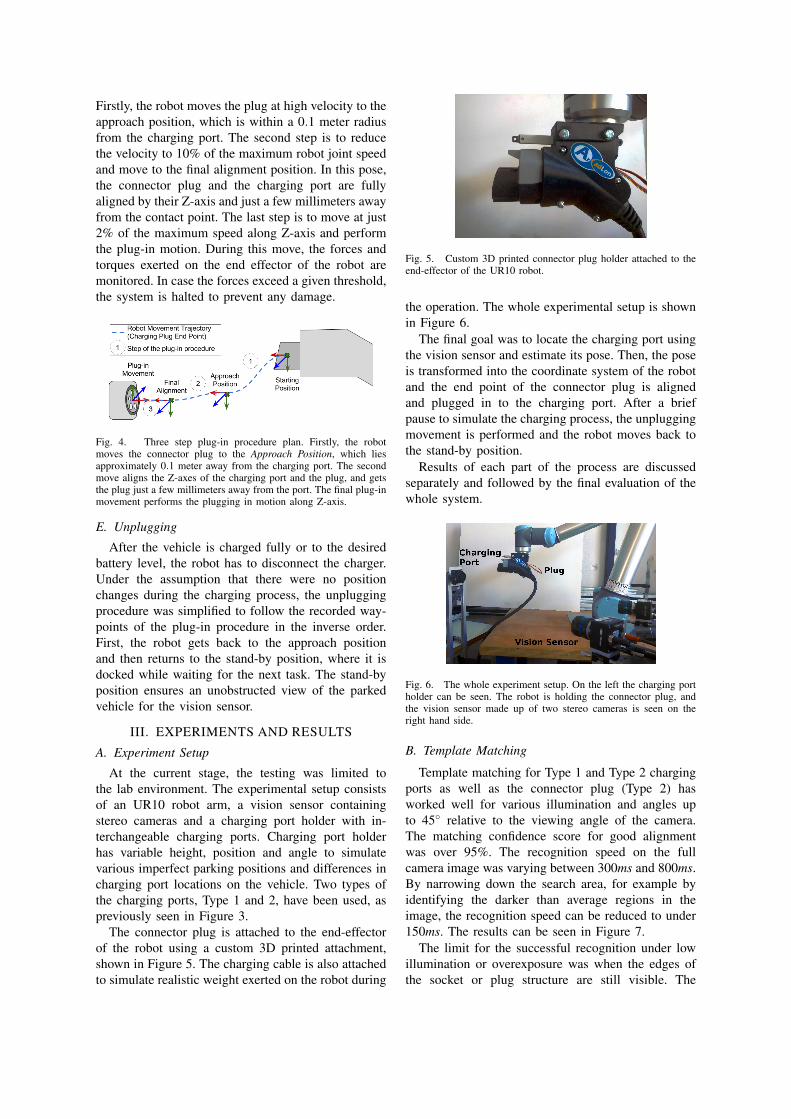
After the pose of the charging port is calculated, thecoordinate system is assigned with the origin placedat the center of the plug and Z-axis looking outwards.Similarly, the coordinate system is assigned to theconnector plug, which is held by the robot. The goalof the plug-in procedure is to perfectly align connectorplug with the charging port, so the last movementis simply along one axis. In order to achieve that, athree-step procedure was used, visualised in Figure 4.
Firstly, the robot moves the plug at high velocity to theapproach position, which is within a 0.1 meter radiusfrom the charging port. The second step is to reducethe velocity to 10% of the maximum robot joint speedand move to the final alignment position. In this pose,the connector plug and the charging port are fullyaligned by their Z-axis and just a few millimeters awayfrom the contact point. The last step is to move at just2% of the maximum speed along Z-axis and performthe plug-in motion. During this move, the forces andtorques exerted on the end effector of the robot aremonitored. In case the forces exceed a given threshold,the system is halted to prevent any damage.
Fig. 4. Three step plug-in procedure plan. Firstly, the robotmoves the connector plug to the Approach Position, which liesapproximately 0.1 meter away from the charging port. The secondmove aligns the Z-axes of the charging port and the plug, and getsthe plug just a few millimeters away from the port. The final plug-inmovement performs the plugging in motion along Z-axis.
E. Unplugging
After the vehicle is charged fully or to the desiredbattery level, the robot has to disconnect the charger.Under the assumption that there were no positionchanges during the charging process, the unpluggingprocedure was simplified to follow the recorded way-points of the plug-in procedure in the inverse order.First, the robot gets back to the approach positionand then returns to the stand-by position, where it isdocked while waiting for the next task. The stand-byposition ensures an unobstructed view of the parkedvehicle for the vision sensor.
III. EXPERIMENTS AND RESULTS
A. Experiment Setup
At the current stage, the testing was limited tothe lab environment. The experimental setup consistsof an UR10 robot arm, a vision sensor containingstereo cameras and a charging port holder with in-terchangeable charging ports. Charging port holderhas variable height, position and angle to simulatevarious imperfect parking positions and differences incharging port locations on the vehicle. Two types ofthe charging ports, Type 1 and 2, have been used, aspreviously seen in Figure 3.
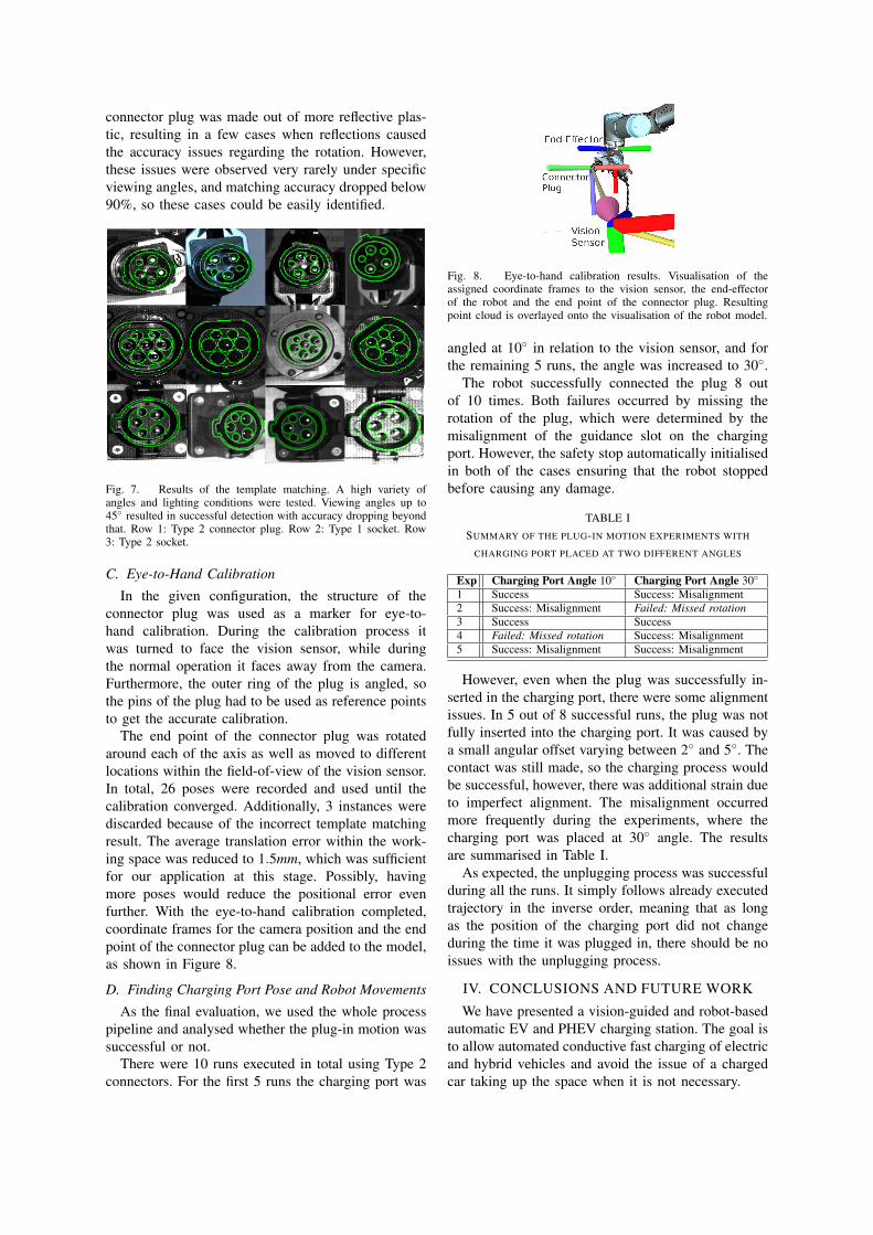
The connector plug is attached to the end-effectorof the robot using a custom 3D printed attachment,shown in Figure 5. The charging cable is also attachedto simulate realistic weight exerted on the robot during
Fig. 5. Custom 3D printed connector plug holder attached to theend-effector of the UR10 robot.
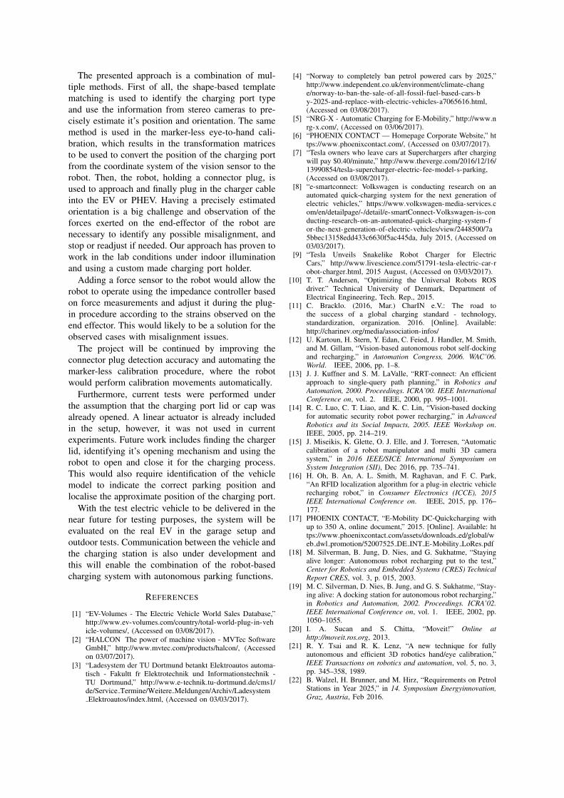
the operation. The whole experimental setup is shownin Figure 6.
The final goal was to locate the charging port usingthe vision sensor and estimate its pose. Then, the poseis transformed into the coordinate system of the robotand the end point of the connector plug is alignedand plugged in to the charging port. After a briefpause to simulate the charging process, the unpluggingmovement is performed and the robot moves back tothe stand-by position.
Results of each part of the process are discussedseparately and followed by the final evaluation of thewhole system.
Fig. 6. The whole experiment setup. On the left the charging portholder can be seen. The robot is holding the connector plug, andthe vision sensor made up of two stereo cameras is seen on theright hand side.
B. Template Matching
Template matching for Type 1 and Type 2 chargingports as well as the connector plug (Type 2) hasworked well for various illumination and angles upto 45◦ relative to the viewing angle of the camera.The matching confidence score for good alignmentwas over 95%. The recognition speed on the fullcamera image was varying between 300ms and 800ms.By narrowing down the search area, for example byidentifying the darker than average regions in theimage, the recognition speed can be reduced to under150ms. The results can be seen in Figure 7.
The limit for the successful recognition under lowillumination or overexposure was when the edges ofthe socket or plug structure are still visible. The
connector plug was made out of more reflective plas-tic, resulting in a few cases when reflections causedthe accuracy issues regarding the rotation. However,these issues were observed very rarely under specificviewing angles, and matching accuracy dropped below90%, so these cases could be easily identified.
Fig. 7. Results of the template matching. A high variety ofangles and lighting conditions were tested. Viewing angles up to45◦ resulted in successful detection with accuracy dropping beyondthat. Row 1: Type 2 connector plug. Row 2: Type 1 socket. Row3: Type 2 socket.
C. Eye-to-Hand Calibration
In the given configuration, the structure of theconnector plug was used as a marker for eye-to-hand calibration. During the calibration process itwas turned to face the vision sensor, while duringthe normal operation it faces away from the camera.Furthermore, the outer ring of the plug is angled, sothe pins of the plug had to be used as reference pointsto get the accurate calibration.
The end point of the connector plug was rotatedaround each of the axis as well as moved to differentlocations within the field-of-view of the vision sensor.In total, 26 poses were recorded and used until thecalibration converged. Additionally, 3 instances werediscarded because of the incorrect template matchingresult. The average translation error within the work-ing space was reduced to 1.5mm, which was sufficientfor our application at this stage. Possibly, havingmore poses would reduce the positional error evenfurther. With the eye-to-hand calibration completed,coordinate frames for the camera position and the endpoint of the connector plug can be added to the model,as shown in Figure 8.
D. Finding Charging Port Pose and Robot Movements
As the final evaluation, we used the whole processpipeline and analysed whether the plug-in motion wassuccessful or not.
There were 10 runs executed in total using Type 2connectors. For the first 5 runs the charging port was
Fig. 8. Eye-to-hand calibration results. Visualisation of theassigned coordinate frames to the vision sensor, the end-effectorof the robot and the end point of the connector plug. Resultingpoint cloud is overlayed onto the visualisation of the robot model.
angled at 10◦ in relation to the vision sensor, and forthe remaining 5 runs, the angle was increased to 30◦.
The robot successfully connected the plug 8 outof 10 times. Both failures occurred by missing therotation of the plug, which were determined by themisalignment of the guidance slot on the chargingport. However, the safety stop automatically initialisedin both of the cases ensuring that the robot stoppedbefore causing any damage.
TABLE ISUMMARY OF THE PLUG-IN MOTION EXPERIMENTS WITH
CHARGING PORT PLACED AT TWO DIFFERENT ANGLES
Exp Charging Port Angle 10◦ Charging Port Angle 30◦
However, even when the plug was successfully in-serted in the charging port, there were some alignmentissues. In 5 out of 8 successful runs, the plug was notfully inserted into the charging port. It was caused bya small angular offset varying between 2◦ and 5◦. Thecontact was still made, so the charging process wouldbe successful, however, there was additional strain dueto imperfect alignment. The misalignment occurredmore frequently during the experiments, where thecharging port was placed at 30◦ angle. The resultsare summarised in Table I.
As expected, the unplugging process was successfulduring all the runs. It simply follows already executedtrajectory in the inverse order, meaning that as longas the position of the charging port did not changeduring the time it was plugged in, there should be noissues with the unplugging process.
IV. CONCLUSIONS AND FUTURE WORK
We have presented a vision-guided and robot-basedautomatic EV and PHEV charging station. The goal isto allow automated conductive fast charging of electricand hybrid vehicles and avoid the issue of a chargedcar taking up the space when it is not necessary.
The presented approach is a combination of mul-tiple methods. First of all, the shape-based templatematching is used to identify the charging port typeand use the information from stereo cameras to pre-cisely estimate it’s position and orientation. The samemethod is used in the marker-less eye-to-hand cali-bration, which results in the transformation matricesto be used to convert the position of the charging portfrom the coordinate system of the vision sensor to therobot. Then, the robot, holding a connector plug, isused to approach and finally plug in the charger cableinto the EV or PHEV. Having a precisely estimatedorientation is a big challenge and observation of theforces exerted on the end-effector of the robot arenecessary to identify any possible misalignment, andstop or readjust if needed. Our approach has proven towork in the lab conditions under indoor illuminationand using a custom made charging port holder.
Adding a force sensor to the robot would allow therobot to operate using the impedance controller basedon force measurements and adjust it during the plug-in procedure according to the strains observed on theend effector. This would likely to be a solution for theobserved cases with misalignment issues.
The project will be continued by improving theconnector plug detection accuracy and automating themarker-less calibration procedure, where the robotwould perform calibration movements automatically.
Furthermore, current tests were performed underthe assumption that the charging port lid or cap wasalready opened. A linear actuator is already includedin the setup, however, it was not used in currentexperiments. Future work includes finding the chargerlid, identifying it’s opening mechanism and using therobot to open and close it for the charging process.This would also require identification of the vehiclemodel to indicate the correct parking position andlocalise the approximate position of the charging port.
With the test electric vehicle to be delivered in thenear future for testing purposes, the system will beevaluated on the real EV in the garage setup andoutdoor tests. Communication between the vehicle andthe charging station is also under development andthis will enable the combination of the robot-basedcharging system with autonomous parking functions.
REFERENCES
[1] “EV-Volumes - The Electric Vehicle World Sales Database,”http://www.ev-volumes.com/country/total-world-plug-in-vehicle-volumes/, (Accessed on 03/08/2017).
[2] “HALCON The power of machine vision - MVTec SoftwareGmbH,” http://www.mvtec.com/products/halcon/, (Accessedon 03/07/2017).
[3] “Ladesystem der TU Dortmund betankt Elektroautos automa-tisch - Fakultt fr Elektrotechnik und Informationstechnik -TU Dortmund,” http://www.e-technik.tu-dortmund.de/cms1/de/Service Termine/Weitere Meldungen/Archiv/LadesystemElektroautos/index.html, (Accessed on 03/03/2017).
[4] “Norway to completely ban petrol powered cars by 2025,”http://www.independent.co.uk/environment/climate-change/norway-to-ban-the-sale-of-all-fossil-fuel-based-cars-by-2025-and-replace-with-electric-vehicles-a7065616.html,(Accessed on 03/08/2017).
[5] “NRG-X - Automatic Charging for E-Mobility,” http://www.nrg-x.com/, (Accessed on 03/06/2017).
[7] “Tesla owners who leave cars at Superchargers after chargingwill pay $0.40/minute,” http://www.theverge.com/2016/12/16/13990854/tesla-supercharger-electric-fee-model-s-parking,(Accessed on 03/08/2017).
[8] “e-smartconnect: Volkswagen is conducting research on anautomated quick-charging system for the next generation ofelectric vehicles,” https://www.volkswagen-media-services.com/en/detailpage/-/detail/e-smartConnect-Volkswagen-is-conducting-research-on-an-automated-quick-charging-system-for-the-next-generation-of-electric-vehicles/view/2448500/7a5bbec13158edd433c6630f5ac445da, July 2015, (Accessed on03/03/2017).
[9] “Tesla Unveils Snakelike Robot Charger for ElectricCars,” http://www.livescience.com/51791-tesla-electric-car-robot-charger.html, 2015 August, (Accessed on 03/03/2017).
[10] T. T. Andersen, “Optimizing the Universal Robots ROSdriver.” Technical University of Denmark, Department ofElectrical Engineering, Tech. Rep., 2015.
[11] C. Bracklo. (2016, Mar.) CharIN e.V.: The road tothe success of a global charging standard - technology,standardization, organization. 2016. [Online]. Available:http://charinev.org/media/association-infos/
[12] U. Kartoun, H. Stern, Y. Edan, C. Feied, J. Handler, M. Smith,and M. Gillam, “Vision-based autonomous robot self-dockingand recharging,” in Automation Congress, 2006. WAC’06.World. IEEE, 2006, pp. 1–8.
[13] J. J. Kuffner and S. M. LaValle, “RRT-connect: An efficientapproach to single-query path planning,” in Robotics andAutomation, 2000. Proceedings. ICRA’00. IEEE InternationalConference on, vol. 2. IEEE, 2000, pp. 995–1001.
[14] R. C. Luo, C. T. Liao, and K. C. Lin, “Vision-based dockingfor automatic security robot power recharging,” in AdvancedRobotics and its Social Impacts, 2005. IEEE Workshop on.IEEE, 2005, pp. 214–219.
[15] J. Miseikis, K. Glette, O. J. Elle, and J. Torresen, “Automaticcalibration of a robot manipulator and multi 3D camerasystem,” in 2016 IEEE/SICE International Symposium onSystem Integration (SII), Dec 2016, pp. 735–741.
[16] H. Oh, B. An, A. L. Smith, M. Raghavan, and F. C. Park,“An RFID localization algorithm for a plug-in electric vehiclerecharging robot,” in Consumer Electronics (ICCE), 2015IEEE International Conference on. IEEE, 2015, pp. 176–177.
[17] PHOENIX CONTACT, “E-Mobility DC-Quickcharging withup to 350 A, online document,” 2015. [Online]. Available: https://www.phoenixcontact.com/assets/downloads ed/global/web dwl promotion/52007525 DE INT E-Mobility LoRes.pdf
[18] M. Silverman, B. Jung, D. Nies, and G. Sukhatme, “Stayingalive longer: Autonomous robot recharging put to the test,”Center for Robotics and Embedded Systems (CRES) TechnicalReport CRES, vol. 3, p. 015, 2003.
[19] M. C. Silverman, D. Nies, B. Jung, and G. S. Sukhatme, “Stay-ing alive: A docking station for autonomous robot recharging,”in Robotics and Automation, 2002. Proceedings. ICRA’02.IEEE International Conference on, vol. 1. IEEE, 2002, pp.1050–1055.
[20] I. A. Sucan and S. Chitta, “Moveit!” Online athttp://moveit.ros.org, 2013.
[21] R. Y. Tsai and R. K. Lenz, “A new technique for fullyautonomous and efficient 3D robotics hand/eye calibration,”IEEE Transactions on robotics and automation, vol. 5, no. 3,pp. 345–358, 1989.
[22] B. Walzel, H. Brunner, and M. Hirz, “Requirements on PetrolStations in Year 2025,” in 14. Symposium Energyinnovation,Graz, Austria, Feb 2016.