39
Lecture overview 3G UMTS concept UTRA FDD TDD
Lecture overview
3G
UMTS concept
UTRA
FDD
TDD
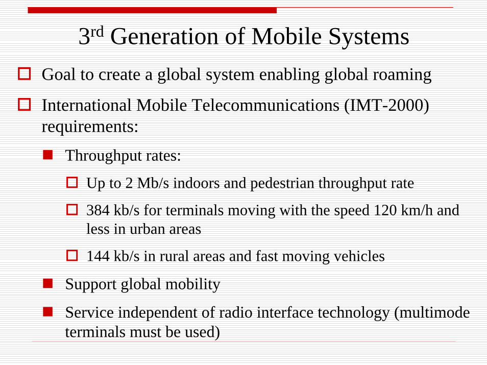
3rd Generation of Mobile SystemsGoal to create a global system enabling global roaming
International Mobile Telecommunications (IMT-2000) requirements:
Throughput rates:
Up to 2 Mb/s indoors and pedestrian throughput rate
384 kb/s for terminals moving with the speed 120 km/h and less in urban areas
144 kb/s in rural areas and fast moving vehicles
Support global mobility
Service independent of radio interface technology (multimode terminals must be used)
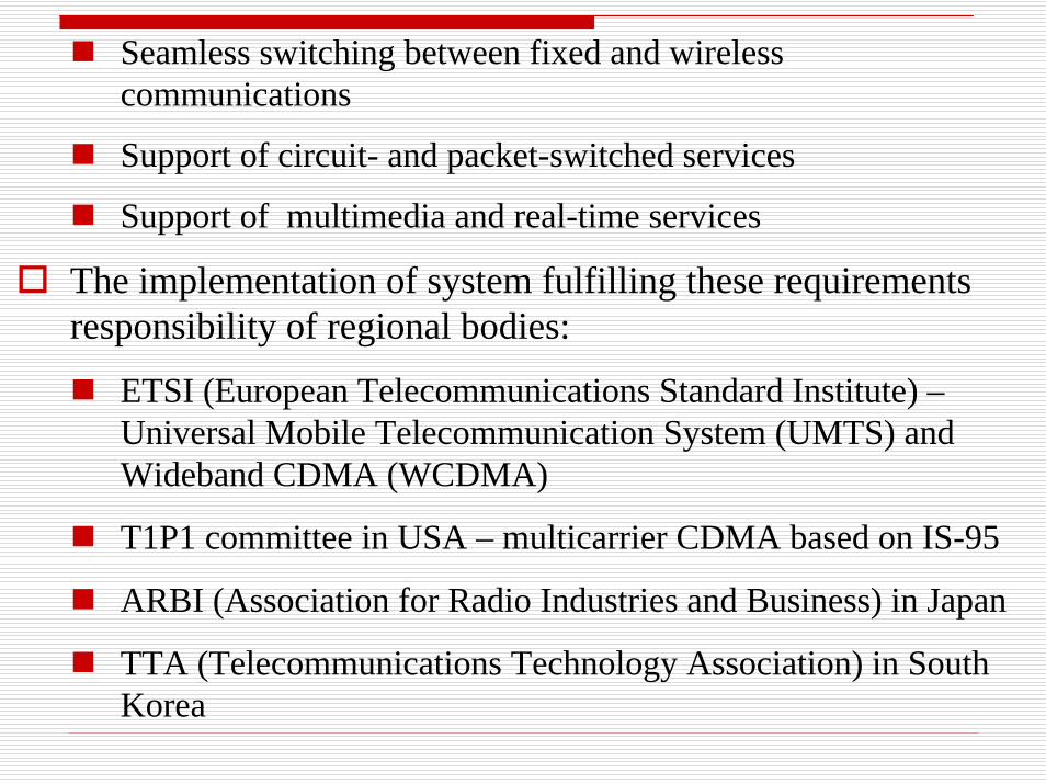
Seamless switching between fixed and wireless communications
Support of circuit- and packet-switched services
Support of multimedia and real-time services
The implementation of system fulfilling these requirements responsibility of regional bodies:
ETSI (European Telecommunications Standard Institute) –Universal Mobile Telecommunication System (UMTS) and Wideband CDMA (WCDMA)
T1P1 committee in USA – multicarrier CDMA based on IS-95
ARBI (Association for Radio Industries and Business) in Japan
TTA (Telecommunications Technology Association) in South Korea
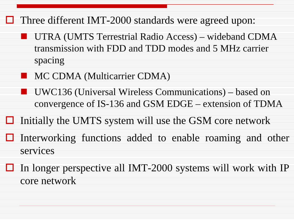
Three different IMT-2000 standards were agreed upon:UTRA (UMTS Terrestrial Radio Access) – wideband CDMA transmission with FDD and TDD modes and 5 MHz carrier spacing MC CDMA (Multicarrier CDMA)UWC136 (Universal Wireless Communications) – based on convergence of IS-136 and GSM EDGE – extension of TDMA
Initially the UMTS system will use the GSM core network Interworking functions added to enable roaming and other servicesIn longer perspective all IMT-2000 systems will work with IP core network
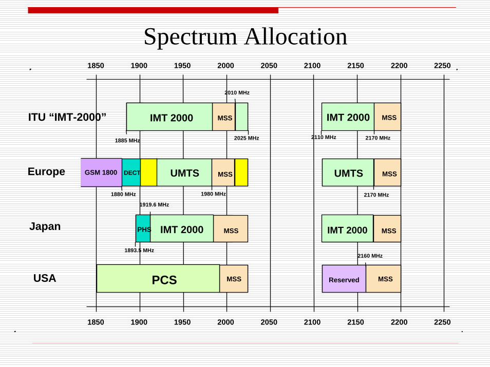
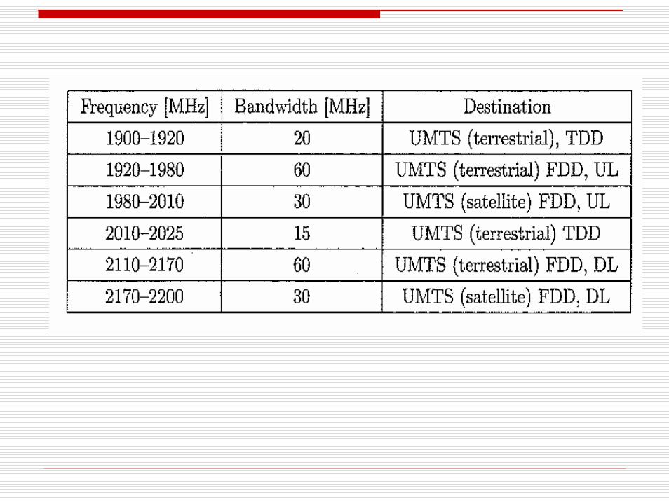
Spectrum Allocation1850 1900 1950 2000 2050 2100 2150 2200 2250
1850 1900 1950 2000 2050 2100 2150 2200 2250
ITU “IMT-2000”
Europe
Japan
USA
1885 MHz 2025 MHz
IMT 2000
UMTSGSM 1800 DECT MSS
1880 MHz 1980 MHz
MSS
MSSIMT 2000PHS
PCS
2010 MHz
IMT 2000
MSSUMTS
MSSReserved
MSSIMT 2000
2160 MHz
2110 MHz
1893.5 MHz
1919.6 MHz
2170 MHz
2170 MHz
MSS MSS
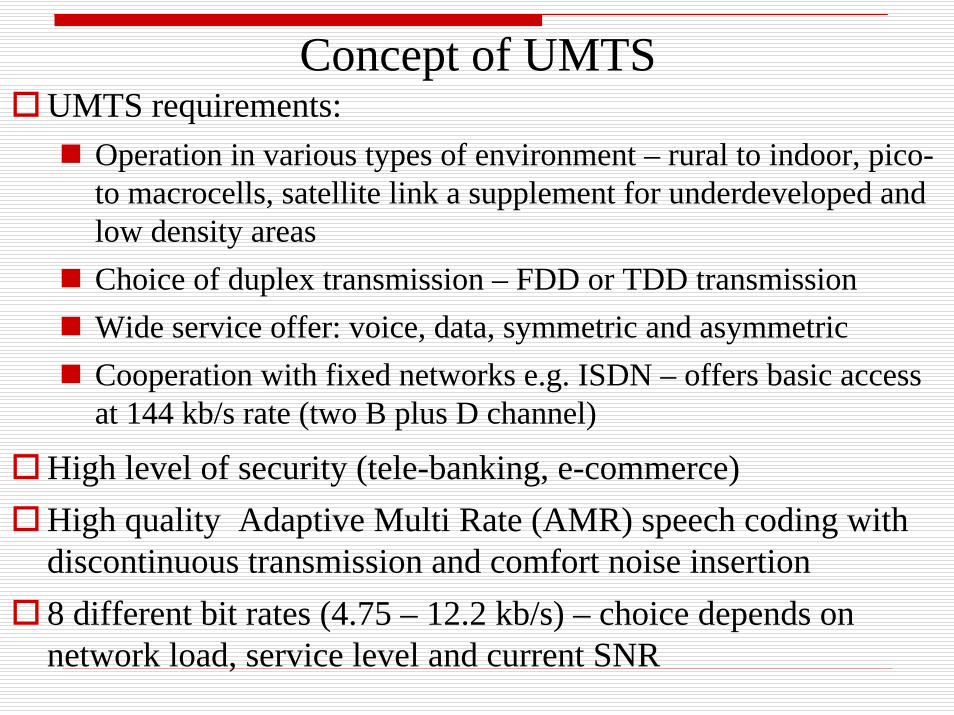
UMTS requirements:Operation in various types of environment – rural to indoor, pico-to macrocells, satellite link a supplement for underdeveloped and low density areasChoice of duplex transmission – FDD or TDD transmissionWide service offer: voice, data, symmetric and asymmetric Cooperation with fixed networks e.g. ISDN – offers basic access at 144 kb/s rate (two B plus D channel)
High level of security (tele-banking, e-commerce)High quality Adaptive Multi Rate (AMR) speech coding with discontinuous transmission and comfort noise insertion8 different bit rates (4.75 – 12.2 kb/s) – choice depends on network load, service level and current SNR
Concept of UMTS
UMTS Radio Access Network ArchitectureThere are 3 main elements of architecture:
User Equipment (UE):
Mobile equipment – radio terminal
UMTS Subscriber Identity Module (USIM) – smart card similar to SIM in GSM – contains subscriber identity, authentication algorithms, encryption keys etc
UMTS Terrestrial Radio Access Network (UTRAN) –
BS’s called Node B – channel coding, data interleaving rate matching, modulation etc.
Radio Network Controllers (RNCs) – manage radio resources assigned to them, participate in handovers, connected to single MSC/VLR for routing of circuit-switched and to single SGSN for packet-switched traffic
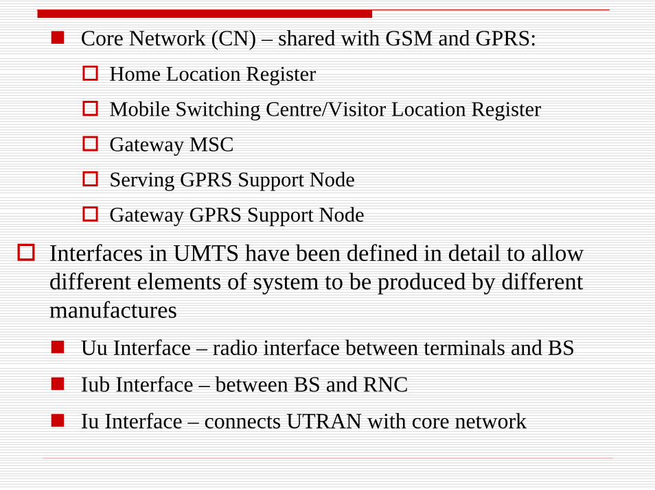
Core Network (CN) – shared with GSM and GPRS:Home Location Register
Mobile Switching Centre/Visitor Location Register
Gateway MSC
Serving GPRS Support Node
Gateway GPRS Support Node
Interfaces in UMTS have been defined in detail to allow different elements of system to be produced by different manufactures
Uu Interface – radio interface between terminals and BS
Iub Interface – between BS and RNC
Iu Interface – connects UTRAN with core network
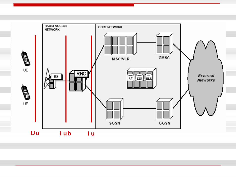
Uu Iub Iu
UMTS Air InterfaceUMTS Terrestrial Radio Access (UTRA – also known as Wideband CDMA) was defined by the 3rd Generation Partnership Project (3GPP)
It has 2 modes of operation differing in applications and air interface:
Paired bands operate in FDDUnpaired use TDD mode
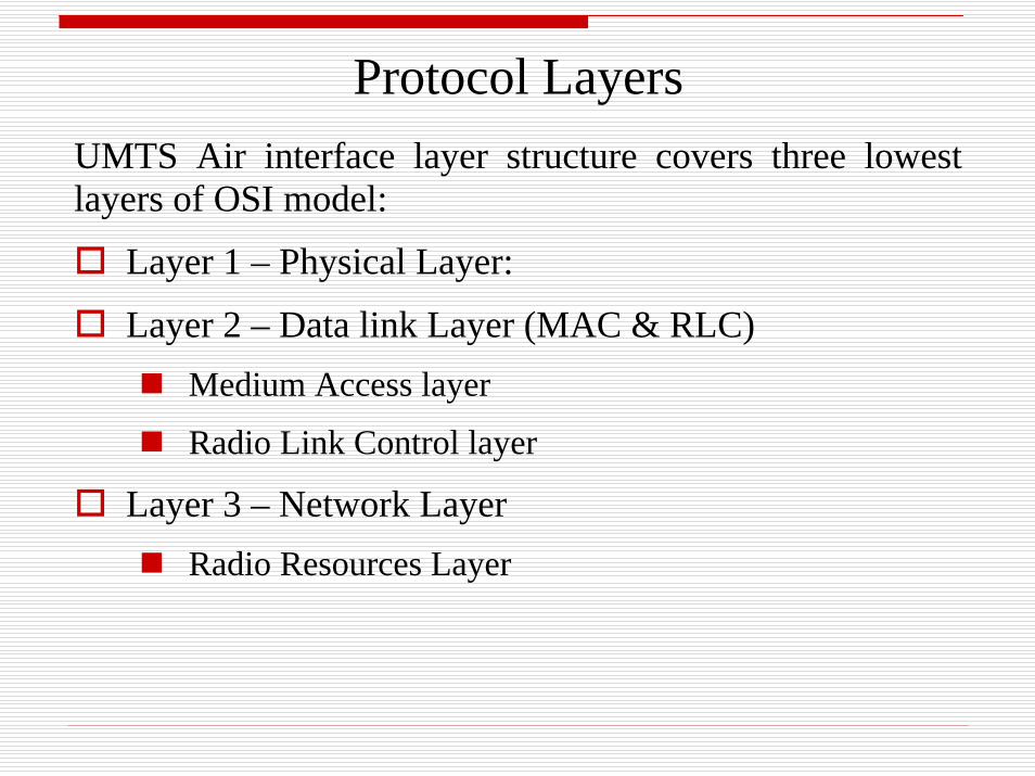
Protocol LayersUMTS Air interface layer structure covers three lowest layers of OSI model:
Layer 1 – Physical Layer:
Layer 2 – Data link Layer (MAC & RLC)Medium Access layer
Radio Link Control layer
Layer 3 – Network LayerRadio Resources Layer
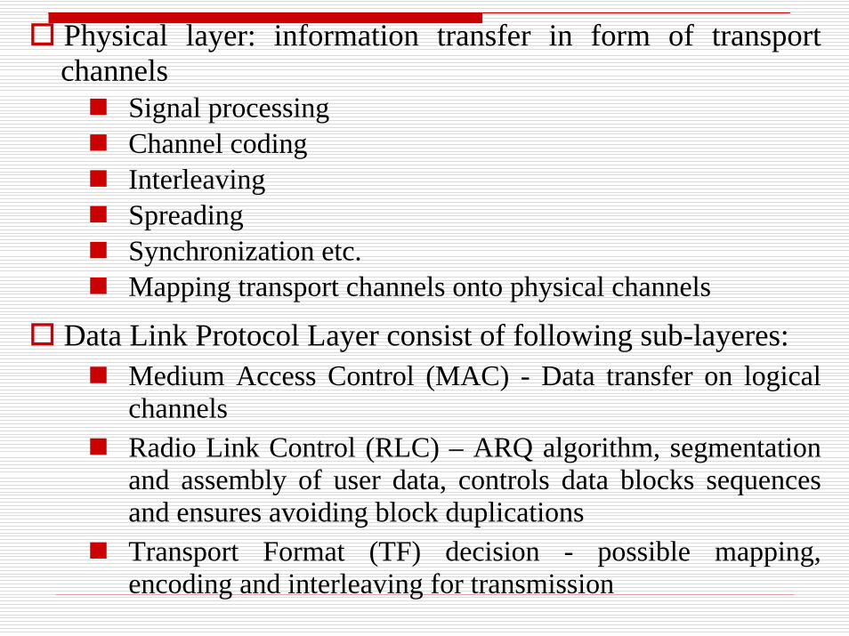
Physical layer: information transfer in form of transport channels
Signal processingChannel codingInterleavingSpreadingSynchronization etc.Mapping transport channels onto physical channels
Data Link Protocol Layer consist of following sub-layeres:Medium Access Control (MAC) - Data transfer on logical channelsRadio Link Control (RLC) – ARQ algorithm, segmentation and assembly of user data, controls data blocks sequences and ensures avoiding block duplicationsTransport Format (TF) decision - possible mapping, encoding and interleaving for transmission
Packet Data Convergence Protocol (PDCP) – transmission and reception of networks Protocol Data Units (PDU) in acknowledged or unacknowledged or transparent RLC modesBroadcast/Multicast Control (BMC) broadcast and multicast transmission in transparent or unacknowledged mode
Radio Resource Control (RRC) (Network Layer) –broadcasting system information, radio resources handling, control of quality of service requests, measurements reports and control (slow power control)
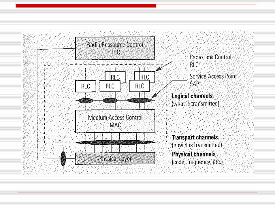
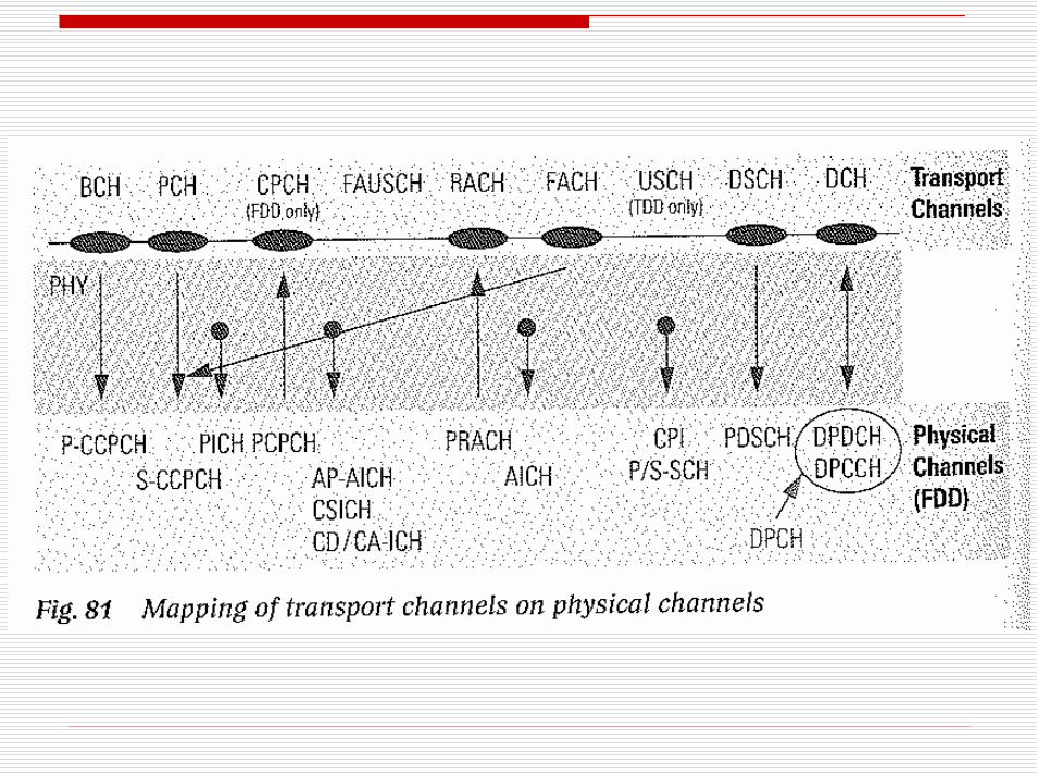
Communication between RRC and RLC/MAC is performed through logical channels, which are then mapped onto transport channels.Transport channels are then mapped onto physical channels
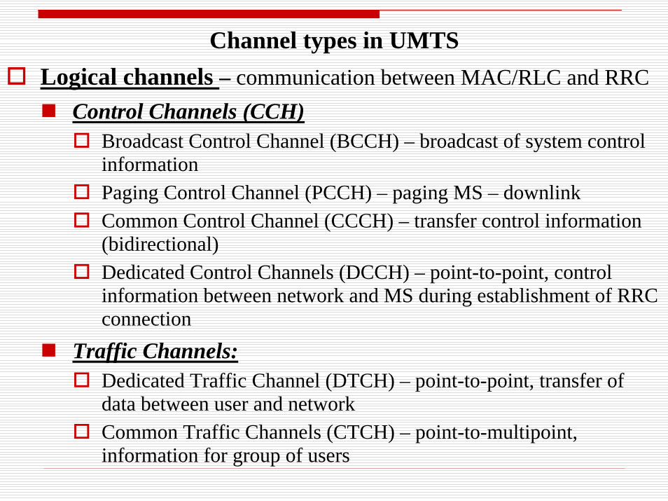
Channel types in UMTSLogical channels – communication between MAC/RLC and RRC
Control Channels (CCH)Broadcast Control Channel (BCCH) – broadcast of system control informationPaging Control Channel (PCCH) – paging MS – downlinkCommon Control Channel (CCCH) – transfer control information (bidirectional)Dedicated Control Channels (DCCH) – point-to-point, control information between network and MS during establishment of RRC connection
Traffic Channels: Dedicated Traffic Channel (DTCH) – point-to-point, transfer of data between user and networkCommon Traffic Channels (CTCH) – point-to-multipoint, information for group of users
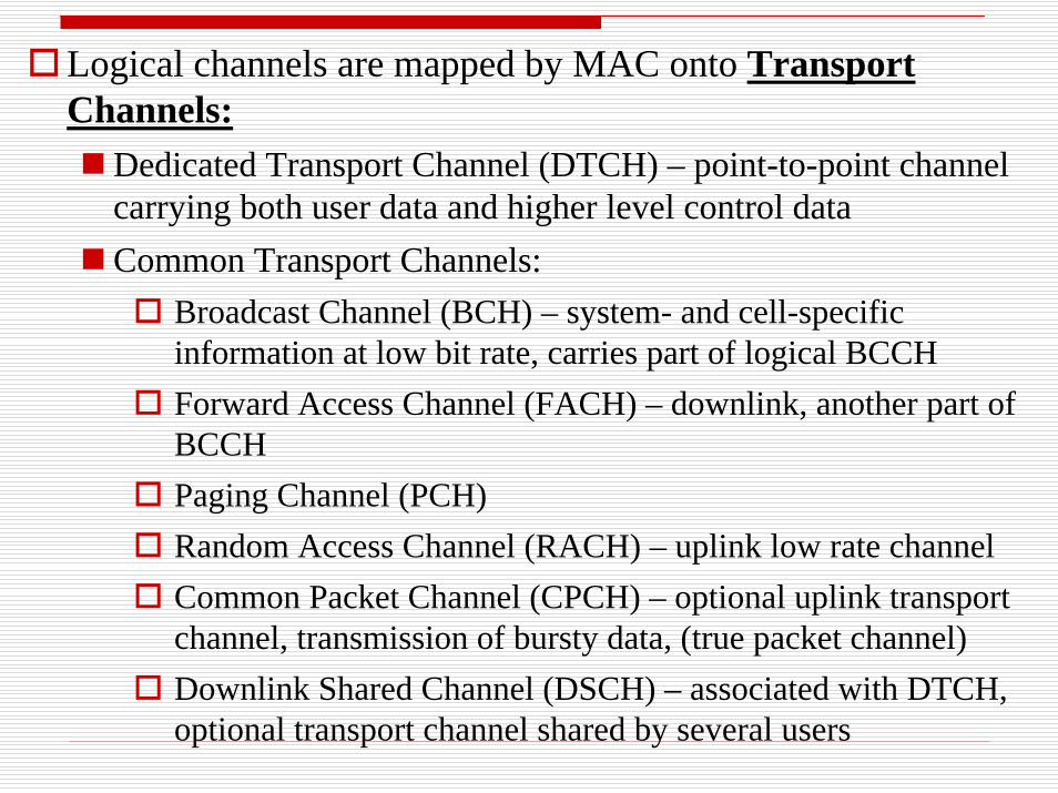
Logical channels are mapped by MAC onto Transport Channels:
Dedicated Transport Channel (DTCH) – point-to-point channel carrying both user data and higher level control dataCommon Transport Channels:
Broadcast Channel (BCH) – system- and cell-specific information at low bit rate, carries part of logical BCCHForward Access Channel (FACH) – downlink, another part of BCCHPaging Channel (PCH)Random Access Channel (RACH) – uplink low rate channelCommon Packet Channel (CPCH) – optional uplink transport channel, transmission of bursty data, (true packet channel)Downlink Shared Channel (DSCH) – associated with DTCH, optional transport channel shared by several users
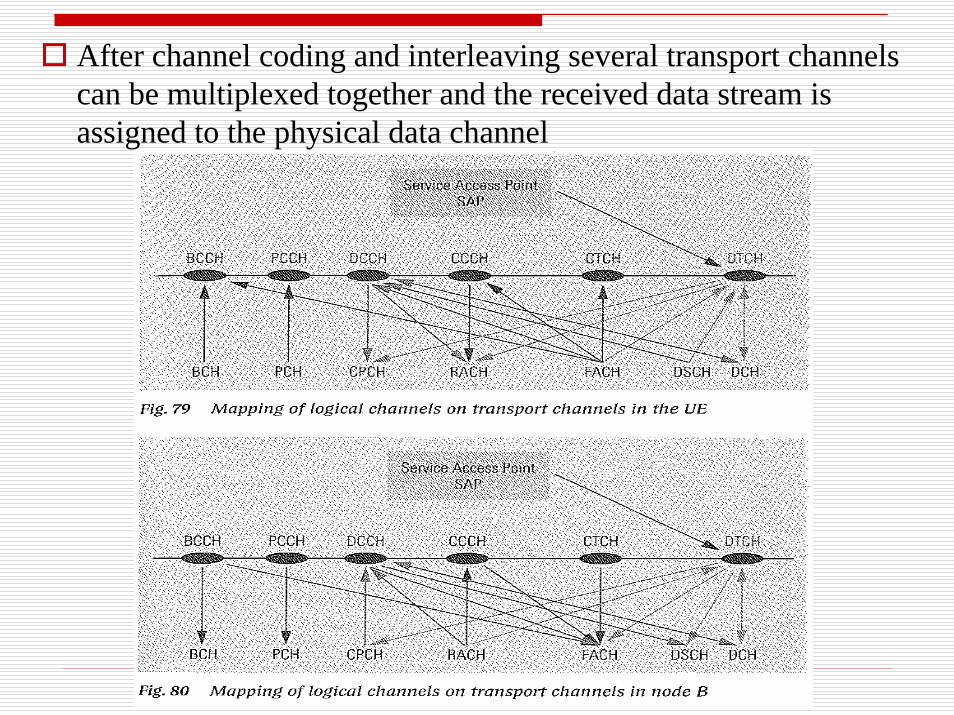
After channel coding and interleaving several transport channelscan be multiplexed together and the received data stream is assigned to the physical data channel
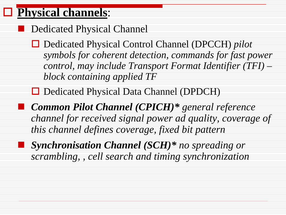
Physical channels:Dedicated Physical Channel
Dedicated Physical Control Channel (DPCCH) pilot symbols for coherent detection, commands for fast power control, may include Transport Format Identifier (TFI) –block containing applied TF Dedicated Physical Data Channel (DPDCH)
Common Pilot Channel (CPICH)* general reference channel for received signal power ad quality, coverage of this channel defines coverage, fixed bit patternSynchronisation Channel (SCH)* no spreading or scrambling, , cell search and timing synchronization
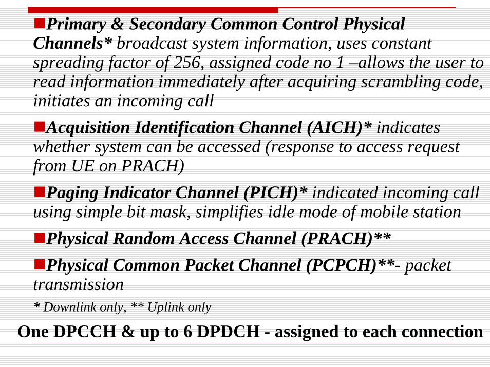
Primary & Secondary Common Control Physical Channels* broadcast system information, uses constant spreading factor of 256, assigned code no 1 –allows the user to read information immediately after acquiring scrambling code, initiates an incoming call
Acquisition Identification Channel (AICH)* indicates whether system can be accessed (response to access request from UE on PRACH)
Paging Indicator Channel (PICH)* indicated incoming call using simple bit mask, simplifies idle mode of mobile station
Physical Random Access Channel (PRACH)** Physical Common Packet Channel (PCPCH)**- packet
transmission* Downlink only, ** Uplink only
One DPCCH & up to 6 DPDCH - assigned to each connection
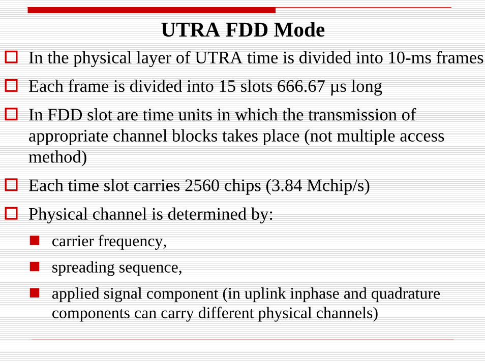
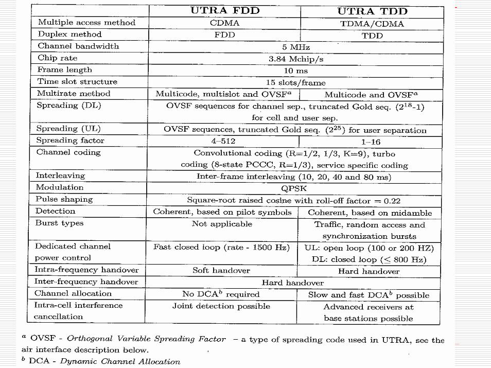
UTRA FDD ModeIn the physical layer of UTRA time is divided into 10-ms framesEach frame is divided into 15 slots 666.67 µs longIn FDD slot are time units in which the transmission of appropriate channel blocks takes place (not multiple access method)Each time slot carries 2560 chips (3.84 Mchip/s)Physical channel is determined by:
carrier frequency, spreading sequence, applied signal component (in uplink inphase and quadraturecomponents can carry different physical channels)
In uplink the binary stream of DPDCH is fed to the in-phase input, DPCCH to quadrature input of the transmitterIf there is more than 1 DPDCH odd-numbered channels are transmitted using in-phase and even-numbered using quadraturecomponent DPDCH – transmits user dataDPCCH – pilot signal for channel estimation, TFI block (format of the DPDCH), Feedback Information for downlink diversity and Transmit Power ControlBoth data streams are spread using two different mutually orthogonal channelisation codesDue to different bit rates in both channels there could be powerdifference between both components. Therefore applied spreading matches the current data rate
Cell search:MS searchers for Primary Synchronisation Channel (SCH – physical channel in form of 256-chip sentence common to all cells used in downlink). It allows for allocation of the starting point of the slots. MS chooses the cell with strongest signalNext MS acquire the frame synchronisation and find a code group used in secondary SCH. There are 64 possible secondary synchronisation code words applied in this channel each determines different code groupFinding the scrambling code – MS correlates received signal with all possible scrambling signals belonging to the given code group. After this the MS is able to read the primary common control channel, which holds system parameters sent on broadcast channel.
Once in the network MS is allocated a paging group. It reads Paging Indicator Channel (PICH) for its paging indicator, stating that there is a message for it in the Common Control Channel
Power Control – realised in a open and closed loop Closed loop control is performed in each slot and the resulting decision on reduction/increase in power is transmitted using DPCCH
Handover in UTRA:Soft handover – all cells operate on the same frequency therefore MS can be connected to multiple BS simultaneously. Uplink signal is received by all BS’s participating in handover and combined to perform macro-diversity. Softer handover – when MS is connected to 2 sectors served by the same BS
Inter-frequency handover – when BS’s transmit on different frequency (e.g. if MS moves from pico- cell to micro-cell etc.). MS employing dual receiver can perform the space diversity, in single receiver a compressed mode is used – with certain period BS transmits frame content in a shorter time (5 instead of 10 ms). Rest of the frame is used by MS for measurement at different carrier frequency. Reduction in frame length is achieved by codepuncturing and changing FET
Handover between FDD and TDD is possible if MS can operated in dual mode
Handover between UTRA and GSM is called a intrer-system handover
UTRA TDD ModeUses unpaired spectral bands Time can be asymmetrically divided between uplink and downlink - dynamic adjustment to current traffic.
Symmetric/asymmetric with multiple switchingSymmetric/asymmetric with single switchingAt least one slot has to be assigned in uplink and one in downlink in each frame
Frame lasts 10 ms and is divided into 15 slotsPhysical channel is determined by carrier frequency, time slot within the frame and applied spreading sequence.
Time slot lasts 2560 chips, transmission in form of bursts Each burst has 2 data fields, mid-amble and ends with a guard time Transmitted data is spread in the data fields in 2 steps using channelisation code and a complex scrambling codeHandover – only hard handover by several types:
TDD - TDDTDD - FDDWCDMA (TDD) - GSM
Establishing the radio connectionStarts via a random access procedure using the PRACH channel - uplink, response to paging message or initiated by UERRC Connection Request:
establishing cause (to determine required QoS)Transmit UE identityReports on initial channel measurements
RRC Connection Setup – assignment of dedicated control channel to the mobile station (frequency channel no., max. transmit power, scrambling code, spreading code)RRC Connection Setup Complete - UE can activate uplink DPCCH – closed power control, confirmation of the connection setup
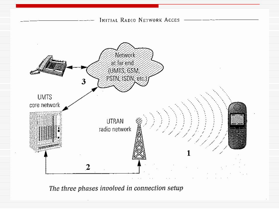
Three phases of connection establishment:Radio connection establishment
Paging or initiated by random access procedureEnd of phase – dedicated logical control channel exists to allow Node B and UE o conversePhysical layer power control responsible for connection quality
Connection between UE and core network (MSC or SN)identification of UE through authentication procedure (comparing subscriber data with HLR)Sequrity mechanisms established (data encryption)
Connection between UE and requested party – radio connection between parties established with desired QoS
Separate phases allow network components to act independently.It minimises burden upon the rest of the network.
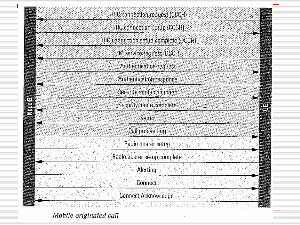
Mobile Originated Call
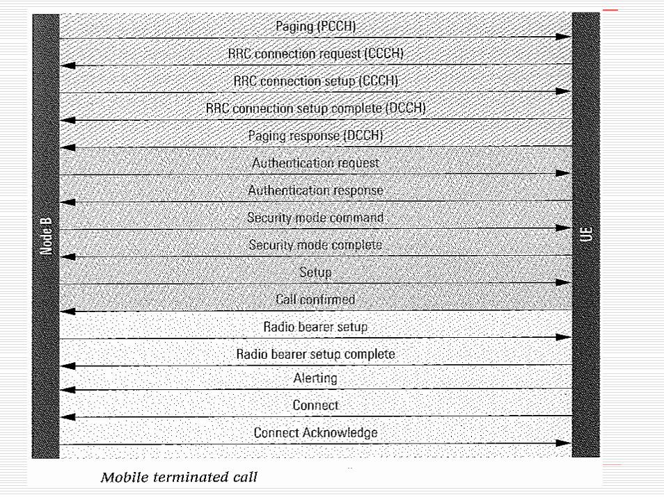
Mobile Terminated Call
Evolution of 3G Systems3G Partnership Project and 3G Partnership Project 2 work on enhancements to both 3G standards: WCDMA and CDMA 2000The extension are:
Evolution Data-Optimised (1xEV-DO) or High Rate Packet Data
Data optimised evolution of CDMA 2000 by 3GPP22.4 Mb/s (Rev-0) and 3.1 Mb/s (Rev-A) peak downlink rates153.6 kb/s (Rev-0) and 1.8 Mb/s (Rev-A) in uplinkStandardisation of EV-DO Rev B – DL 4.9 Mb/sAll in 1.25 MHz channelInitially in South Korea – now being deployed
High-Speed Downlink Packet Access (HSDPA)Data optimised evolution of WCDMA by 3GPP14 Mb/s peak downlink rates in 5 MHz channel
High-Speed Uplink Packet Access (HSUPA) enhancement in uplink data rates
HSDPA includes:Adaptive Modulation and Coding (AMC - QPSK and 16 QAM)Multi-code operationHybrid Automatic Repeat Request (H-ARQ): FEC + ARQDe-centralised architecture – scheduling moved from Radio Network Controller to Node-B – reduced latency and enabled fast scheduling Reduction in frame length from 10 to 2 ms
Combination of HSDPA and HSUPA is known as High-Speed Packet Access (HSPA)
Enhanced Uplink includes several new physical channels for support of high-speed data transmission for Enhanced Data Channel
Roadmap of 3G enhancements:1xEV-DO Rev 0 first deployed in South Korea and Japan in 2003EV-DO Rev A in Korea and Japan in 2005Commercial launch of HSDPA announced in December 2005HSUPA/HSPA not expected until 2007/2008Long term WCMDA evolution leading to UTRAN Long Term Evolution (3.99G or Evolved UMTS) standards expected in 2007 – products probably available in 2009 or later
Summary
3G
UMTS concept
UTRA
Protocol model
UTRA Channels
FDD
TDD


