3GPP TR 23.800 V12.0.0 (2013-03) Technical Report 3rd Generation Partnership Project; Technical Specification Group Services and System Aspects; Study on Application Based Charging (ABC); Stage 2 (Release 12) The present document has been developed within the 3rd Generation Partnership Project (3GPP TM ) and may be further elaborated for the purposes of 3GPP. The present document has not been subject to any approval process by the 3GPP Organizational Partners and shall not be implemented. This Specification is provided for future development work within 3GPP only. The Organizational Partners accept no liability for any use of this Specification. Specifications and reports for implementation of the 3GPP TM system should be obtained via the 3GPP Organizational Partners' Publications Offices.
Transcript
3GPP TR 23.800 V12.0.0 (2013-03)Technical Report
3rd Generation Partnership Project;Technical Specification Group Services and System Aspects;
Study on Application Based Charging (ABC);Stage 2
(Release 12)
The present document has been developed within the 3rd Generation Partnership Project (3GPP TM) and may be further elaborated for the purposes of 3GPP.The present document has not been subject to any approval process by the 3GPP Organizational Partners and shall not be implemented.This Specification is provided for future development work within 3GPP only. The Organizational Partners accept no liability for any use of this Specification.Specifications and reports for implementation of the 3GPP TM system should be obtained via the 3GPP Organizational Partners' Publications Offices.
3GPP
Keywords3GPP, Architecture, Application, Charging
3GPP
Postal address
3GPP support office address650 Route des Lucioles - Sophia Antipolis
UMTS™ is a Trade Mark of ETSI registered for the benefit of its members3GPP™ is a Trade Mark of ETSI registered for the benefit of its Members and of the 3GPP Organizational PartnersLTE™ is a Trade Mark of ETSI currently being registered for the benefit of its Members and of the 3GPP Organizational PartnersGSM® and the GSM logo are registered and owned by the GSM Association
5 Key Issues.......................................................................................................................................115.1 Key Issue # 1 Applications data flows with non-deducible service data flows templates........................11
6 Solutions..........................................................................................................................................136.1 Solutions for Scenario 1: application usage charging only per IP-CAN session......................................136.1.1 Alternative solution 1: sdf transfer......................................................................................................136.1.1.1 Solutions' assumptions...................................................................................................................136.1.1.2 Reference architecture...................................................................................................................146.1.1.3 Application Detection and Control Rule extension.......................................................................146.1.1.4 Credit management........................................................................................................................156.1.1.5 Termination Action........................................................................................................................166.1.1.5a Reporting.......................................................................................................................................166.1.1.6 Functional Description...................................................................................................................166.1.1.7 Impacts on existing nodes or functionality....................................................................................186.1.2 Alternative solution 2: Sy extension....................................................................................................186.1.2.1 Solutions' assumptions...................................................................................................................186.1.2.2 Reference architecture...................................................................................................................186.1.2.3 Reporting, Credit management and termination action.................................................................196.1.2.4 Functional description....................................................................................................................196.1.2.5 Impacts on existing nodes or functionality....................................................................................196.1.3 Alternative solution 3: TDF marking and PCEF based application charging.....................................196.1.3.1 Solutions' assumptions...................................................................................................................196.1.3.2 Reference architecture, Reporting, Credit management, Termination action...............................196.1.3.3 Functional description....................................................................................................................196.1.3.3.1 General description..................................................................................................................196.1.3.3.2 Principle message flow............................................................................................................206.1.3.3.3 Mechanisms for packet marking..............................................................................................216.1.3.3.4 Mechanisms for TDF counter transfer (variant 4c) only)........................................................216.1.3.4 Impacts on existing nodes or functionality....................................................................................226.1.4 Alternative solution 4: Bi-Directional Marking of Charged Packets..................................................226.1.4.1 Solution assumptions.....................................................................................................................226.1.4.2 Reference architecture...................................................................................................................226.1.4.3 Functional description....................................................................................................................226.1.5 Alternative solution 5: TDF TFT analysis...........................................................................................236.1.5.1 Solutions' assumptions...................................................................................................................236.1.5.2 Reference architecture...................................................................................................................236.1.5.3 ADC rule extension.......................................................................................................................236.1.5.4 Termination Action........................................................................................................................236.1.5.5 Functional description....................................................................................................................236.1.5.6 Impacts on existing nodes or functionality....................................................................................246.1.6 Alternative solution 6: Returning the dropped packet.........................................................................246.1.6.1 Solutions' assumptions...................................................................................................................246.1.6.2 Reference architecture...................................................................................................................246.1.6.3 Functional description....................................................................................................................246.1.6.4 Mechanisms of tunnelling..............................................................................................................246.1.7 Alternative solution 7: Simplified solution for Application Based Charging.....................................246.1.7.1 Solutions' assumptions...................................................................................................................24
3GPP
3GPP TR 23.800 V12.0.0 (2013-03)3Release 12
6.1.7.2 Reference architecture...................................................................................................................256.1.7.3 Application Detection and Control Rule extension.......................................................................256.1.7.4 Credit management........................................................................................................................256.1.7.5 Termination Action........................................................................................................................256.1.7.6 Functional Description...................................................................................................................256.1.7.7 Impacts on existing nodes or functionality....................................................................................266.2 Solutions for Scenario 2: sdf usage charging only per IP-CAN session...................................................266.2.1 Alternative solution 1: sdf transfer......................................................................................................266.2.1.1 Solutions' assumptions...................................................................................................................266.2.1.2 Reference architecture, Reporting, Credit management, Termination action...............................266.2.1.3 Functional description....................................................................................................................266.2.1.4 Impacts on existing nodes or functionality....................................................................................276.2.2 Alternative solution 2: Sy extension....................................................................................................286.2.2.1 Solutions' assumptions...................................................................................................................286.2.2.2 Reference architecture...................................................................................................................286.2.2.3 Reporting, Credit management and termination action.................................................................286.2.2.4 Functional description....................................................................................................................286.2.2.5 Impacts on existing nodes or functionality....................................................................................286.2.3 Alternative solution 3: TDF marking and PCEF based application charging.....................................296.2.3.1 Solutions' assumptions...................................................................................................................296.2.3.2 Reference architecture, Credit management, Termination action.................................................296.2.3.3 Functional description....................................................................................................................296.2.3.4 Impacts on existing nodes or functionality....................................................................................296.2.4 Alternative solution 4: Bi-Directional Marking of Charged Packets..................................................296.2.4.1 Solution assumptions.....................................................................................................................296.2.4.2 Reference architecture...................................................................................................................296.2.4.3 Functional description....................................................................................................................306.2.5 Alternative solution 5: TDF TFT analysis...........................................................................................306.2.5.1 Solutions' assumptions...................................................................................................................306.2.5.2 Reference architecture...................................................................................................................306.2.5.3 PCC rule extension........................................................................................................................306.2.5.4 ADC rule extension.......................................................................................................................306.2.5.5 Termination Action........................................................................................................................306.2.5.6 Functional description....................................................................................................................306.2.5.7 Impacts on existing nodes or functionality....................................................................................316.2.6 Alternative solution 6: Returning the dropped packet.........................................................................316.2.6.1 Solutions' assumption....................................................................................................................316.2.6.2 Reference architecture...................................................................................................................316.2.6.3 Functional description....................................................................................................................316.2.6.4 Mechanisms of tunnelling..............................................................................................................326.3 Solutions for Scenario 3: Both service data flow charging and application usage charging is required per
IP-CAN session.........................................................................................................................................326.3.1 Alternative solution 1: sdf transfer......................................................................................................326.3.1.1 Solutions' assumptions...................................................................................................................326.3.1.2 Reference architecture...................................................................................................................326.3.1.3 Application Detection and Control Rule extension.......................................................................336.3.1.4 Credit management........................................................................................................................336.3.1.5 Termination Action........................................................................................................................336.3.1.5a Reporting.......................................................................................................................................336.3.1.6 Functional Description...................................................................................................................336.3.1.7 Impacts on existing nodes or functionality....................................................................................356.3.2 Alternative solution 2: Sy extension....................................................................................................376.3.2.1 Solutions' assumptions...................................................................................................................376.3.2.2 Reference architecture...................................................................................................................376.3.2.3 Reporting, Credit management and termination action.................................................................376.3.2.4 Functional description....................................................................................................................386.3.2.5 Impacts on existing nodes or functionality....................................................................................386.3.3 Alternative solution 3: Correlation by OCS........................................................................................386.3.3.1 Solutions' assumptions...................................................................................................................386.3.3.2 Reference architecture, ADC Rule extension, Reporting, Credit management, Termination action386.3.3.3 Functional description....................................................................................................................38
3GPP
3GPP TR 23.800 V12.0.0 (2013-03)4Release 12
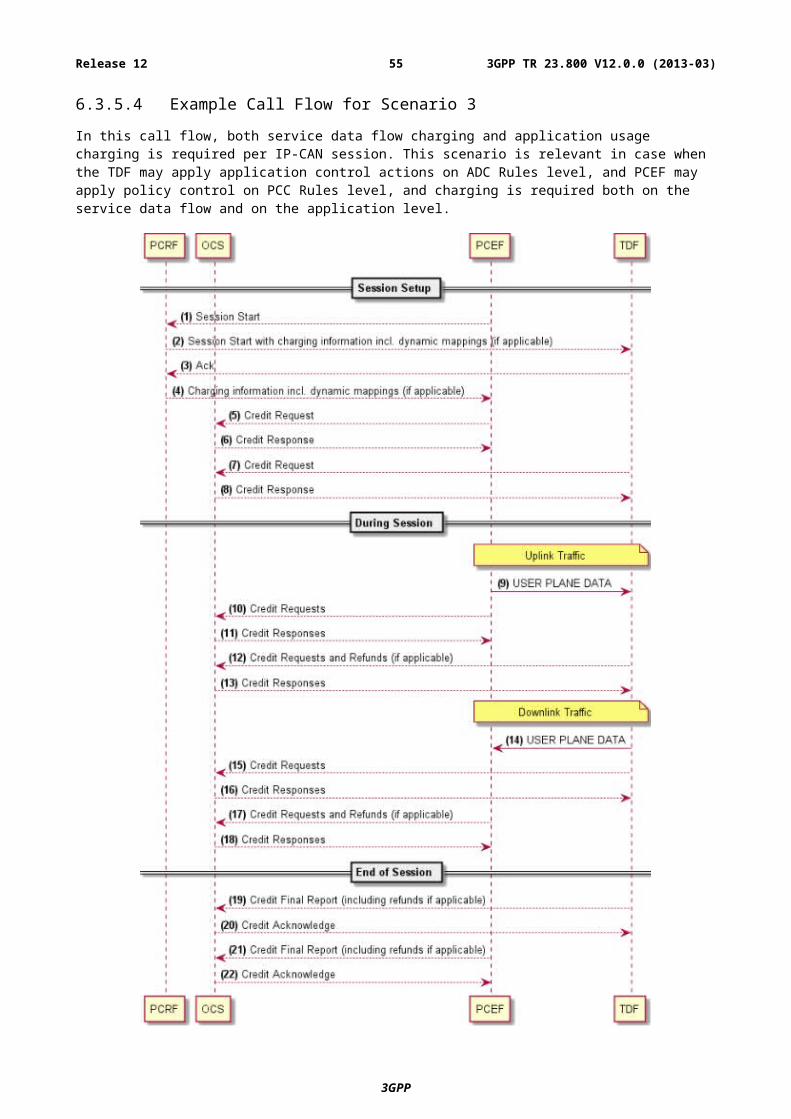
6.3.3.4 Impacts on existing nodes or functionality....................................................................................396.3.4 Alternative solution 4: TDF marking and PCEF based application charging.....................................396.3.4.1 Solutions' assumptions...................................................................................................................396.3.4.2 Reference architecture, Reporting, Credit management, Termination action...............................396.3.4.3 Functional description....................................................................................................................396.3.4.4 Impacts on existing nodes or functionality....................................................................................396.3.5 Alternative solution 5: Bi-Directional Marking of Charged Packets..................................................396.3.5.1 Solution assumptions.....................................................................................................................396.3.5.2 Reference architecture, ADC Rule extension, Reporting, Credit management, Termination action406.3.5.3 Functional description....................................................................................................................406.3.5.4 Example Call Flow for Scenario 3.................................................................................................426.3.5.5 Maintaining Synchronisation between Refunds............................................................................436.3.5.6 Rule Prioritization, Double Charging and Redirections................................................................446.3.5.7 Static and Dynamic Correlation Between Charging Key and Packet Marking.............................446.3.5.8 Mechanisms of Packet Marking....................................................................................................456.3.5.9 Impacts on existing nodes or functionality....................................................................................456.3.6 Alternative solution 6: TDF TFT analysis...........................................................................................456.3.6.1 Solutions' assumptions...................................................................................................................456.3.6.2 Reference architecture...................................................................................................................456.3.6.3 PCC rule extension........................................................................................................................466.3.6.4 ADC rule extension.......................................................................................................................466.3.6.5 Termination Action........................................................................................................................466.3.6.6 Functional description....................................................................................................................476.3.6.6.1 Usage Report............................................................................................................................476.3.6.7 Impacts on existing nodes or functionality....................................................................................486.3.7 Alternative solution 7: Returning the dropped packet.........................................................................486.3.7.1 Solutions' assumptions...................................................................................................................486.3.7.2 Reference architecture...................................................................................................................486.3.7.3 Functional description....................................................................................................................496.3.7.3.1 Application-based charging.....................................................................................................496.3.7.3.2 SDF-based charging.................................................................................................................496.3.7.4 Double Charging............................................................................................................................506.3.7.5 Impacts on existing nodes or functionality....................................................................................506.3.7.6 Mechanisms of tunnelling..............................................................................................................50
7 Evaluation.......................................................................................................................................517.1 Initial analysis of the solutions per traffic handling cases........................................................................517.2 Required modifications and major points per each one of the proposed solutions...................................51
Annex A: Application Based Charging for the applications with deducible service data flows (as supported in Rel-11)................................................................................................54
ForewordThis Technical Report has been produced by the 3rd Generation Partnership Project (3GPP).
The contents of the present document are subject to continuing work within the TSG and may change following formal TSG approval. Should the TSG modify the contents of the present document, it will be re-released by the TSG with an identifying change of release date and an increase in version number as follows:
Version x.y.z
where:
x the first digit:
1 presented to TSG for information;
2 presented to TSG for approval;
3 or greater indicates TSG approved document under change control.
y the second digit is incremented for all changes of substance, i.e. technical enhancements, corrections, updates, etc.
z the third digit is incremented when editorial only changes have been incorporated in the document.
3GPP
3GPP TR 23.800 V12.0.0 (2013-03)7Release 12
1 ScopeThis Technical Report defines key issues and studies PCEF/TDF charging solutions for the network usage of services and applications when TDF performs application detection and control. Both online and offline charging aspects will be considered. The work will be based on the Rel-11 Policy and charging control architecture, including the specification for application detection and control and the corresponding TDF functionality definition, as defined in TS 23.203 [3].
Based on the technical analysis, any needed enhancements/updates to 3GPP functions and interfaces will be identified.
The agreed solutions will be evaluated for subsequent normative specification.
3GPP
3GPP TR 23.800 V12.0.0 (2013-03)8Release 12
2 ReferencesThe following documents contain provisions which, through reference in this text, constitute provisions of the present document.
- References are either specific (identified by date of publication, edition number, version number, etc.) or non-specific.
- For a specific reference, subsequent revisions do not apply.
- For a non-specific reference, the latest version applies. In the case of a reference to a 3GPP document (including a GSM document), a non-specific reference implicitly refers to the latest version of that document in the same Release as the present document.
[1] 3GPP TR 21.905: "Vocabulary for 3GPP Specifications".
[2] 3GPP TR 41.001: "GSM Release specifications".
[3] 3GPP TS 23.203: "Policy and charging control architecture".
3.1 DefinitionsFor the purposes of the present document, the terms and definitions given in TR 21.905 [1] and in TS 23.203 [3] apply.
3.2 AbbreviationsFor the purposes of the present document, the abbreviations given in TR 21.905 [1] and in TS 23.203 [3] apply.
4 Architectural RequirementsIt shall be possible to apply charging for network usage per detected application in the system when TDF performs application detection, according to rules received from the PCRF.
Both online and offline charging shall be supported.
The application based charging shall support the following charging models:
- Volume based charging;
- Time based charging;
- Volume and time based charging;
- Event based charging;
- No charging.
NOTE 1: The charging model - "No charging" implies that charging control is not applicable.
In case of Event based charging, it shall be configured at TDF, per each Application Identifier, which events to count.
NOTE 2: For example, an event may be defined based on Application Start and Stop or number of Application instance identifiers per each application.
In case of Time or Volume&time based charging, the time shall be measured following the same principles as defined by the TS 32.299 [5].
Application based charging shall be applicable when the TDF applies enforcement actions to the detected application's traffic: gating, bandwidth limitation and redirection and the corresponding charging shall be provided properly e.g. gated traffic is not to be counted. When the TDF performs these actions, the architecture shall ensure that there is accurate charging for the network usage by an application (i.e. network usage should not be charged as part of both a service data flow and as part of an application).
Editor's Note: It is FFS which entity and how should control whether traffic should be counted and reported as a part of sdf based charging or as a part of application based charging when sdf and application based charging may overlap.
It shall be possible to apply different rates and charging models per detected application when a user is identified to be roaming from when the user is in the home network. Furthermore, it shall be possible to apply different rates and charging models based on the location of a user, beyond the granularity of roaming.
It shall be possible to apply a separate rate to the network usage for a specific detected application, e.g. allow the user to access an application deemed by the operator as no charge and another application with a rate causing a charge.
It shall be possible to change the rate per detected application based on the time of day.
3GPP
3GPP TR 23.800 V12.0.0 (2013-03)10Release 12
It shall be possible to enforce per-detected application usage limits for the network usage by an application using online charging on a per user basis (may apply to prepaid and post-paid users).
It shall be possible for the online charging system to set and send the thresholds (time and/or volume based) for the amount of remaining credit per detected application. In case it is detected that any of the time based or volume based credit falls below the threshold, a request for credit re-authorization to the OCS with the remaining credit (time and/or volume based) shall be sent.
It shall be possible for the charging system to select the applicable rate based on:
- Home/visited network;
- Time of day;
- IP-CAN specific parameters.
NOTE 3: The same IP-CAN parameters related to access network/subscription/location information as reported for sdf based charging may need to be reported for the application based charging at the beginning of the session and following any of the relevant re-authorization triggers.
The charging system maintains the tariff information, determining the rate based on the above input. Thus the rate may change e.g. as a result of IP-CAN session specific parameters change.
The charging model applicable to a detected application may change as a result of events identified by the OCS (e.g. after having spent a certain amount of time and/or volume, the user gets to use some application for free).
NOTE 4: Some types of changes between charging models are not possible in the 3GPP system. The above requirement, derived from TS 23.203 [3] has not been met for service data flow charging in all instances.
The charging rate or charging model applicable to a detected application may change as a result of having used the application for a certain amount of time and/or volume.
In the case of online charging, it shall be possible to apply an online charging action upon Application Start/Stop events.
It shall be possible to indicate that interactions with the charging systems are not required for a specific detected application, i.e. to perform neither accounting nor credit control for this application, and then no offline charging information is generated.
5 Key Issues
5.1 Key Issue # 1 Applications data flows with non-deducible service data flows templatesThe target of this key issue is to study possible policy control and charging enhancements in order to support online and offline charging aspects for the network usage of services and applications when TDF detects applications and performs enforcement actions as per ADC Rules, received from the PCRF and the detected application uses data flows for which service data flow templates cannot be deduced.
Non deducible SDFs cannot be described by SDF templates or can be described by SDF templates but these SDF templates cannot be applied to unambiguously or efficiently control the application traffic. Examples of such applications are:
- An Application uses (potentially many) very short-lived parallel UDP and/or TCP data flows, for which service data flow filters detected via ADC rules are too short-lived to allow PCC system to control them using SDF templates;
- An Application exchanges several media data flows (e.g. video, audio, file sharing and chat) that should be kept distinct within the same service data flow (e.g. applications carried over HTTP/port 80); or
- Data flows relating to several applications are carried within the same service data flow (for instance, several applications addressed via different HTTP URIs are provided by the same server over the same port).
3GPP
3GPP TR 23.800 V12.0.0 (2013-03)11Release 12
The following relevant scenarios are identified:
- Scenario 1: Only charging for network usage of an application is required for the corresponding IP-CAN session.
- Scenario 2: Only data flow charging is required for the corresponding IP-CAN session;
- Scenario 3: Charging for network usage for both data flows and applications are required for the corresponding IP-CAN session;
NOTE: For Scenario 1, there is no operator's requirement to charge on the sdf basis per specific user/IP-CAN session. For Scenario 2, there is no operator's requirement to charge on the application basis per specific user/IP-CAN session. For all Scenarios, there may be requirement to report charging also for the "remained" traffic e.g. the remaining traffic of IP-CAN session after applying all ADC Rules.
3GPP
3GPP TR 23.800 V12.0.0 (2013-03)12Release 12
6 Solutions
6.1 Solutions for Scenario 1: application usage charging only per IP-CAN sessionThis scenario is relevant in case when the PCEF may apply policy control actions on PCC Rules level, but charging is required only at the application level for applications detected and enforced by TDF.
6.1.1 Alternative solution 1: sdf transfer
These solutions require the TDF to analyse the sdf templates belonging to the active PCC Rules and informing PCRF whether there are overlaps between the PCC Rule's traffic and ADC Rule's traffic.
Upon receiving such information, if there are overlaps, either PCC/ADC Rule adjustment can be made by the PCRF or usage monitoring reports for the overlapping sdf templates can be provided by the PCEF->PCRF->TDF in order to apply charging accurately.
6.1.1.1 Solutions' assumptions
1. When TDF detects application and the detected application's service data flows are non-deducible, it means that they can't be transferred to other entities, but TDF itself is aware of those service data flows.
2. sdf templates can be transferred by the PCRF to the TDF in all traffic handling cases except the following: sdf templates belonging to the PCC Rules not known to the PCRF and PCC Rules with the filters going beyond 5-tuple definition (i.e. PCEF supporting extended packet inspection capabilities) which can be used only on default bearer.
3. In case charging is also required for the remaining traffic of IP-CAN session after applying all ADC Rules, a dedicated new ADC Rule/Application id for that remained traffic can be created and the reporting can be done per that Application Id.
3GPP
3GPP TR 23.800 V12.0.0 (2013-03)13Release 12
6.1.1.2 Reference architecture
Figure 6.1.1.2-1
Editor's note: It is FFS whether Gyn/Gzn is Gy/Gz or an enhancement of Gy/Gz. Whether the Gyn/Gzn is to be renamed is FFS.
6.1.1.3 Application Detection and Control Rule extension
The following parameters within ADC Rules shall be supported for application usage charging, in addition to the parameters already defined in the TS 23.203 [3]:
Table 6.1.1.3-1
Charging This clause defines identities and instructions for charging and accounting that is required for an access point where application usage charging is configured
Charging key The charging system (OCS or OFCS) uses the charging key to determine the tariff to apply for application.
Charging method Indicates the required charging method for the ADC rule.Values: online, offline or neither.
Measurement method Indicates whether the application data volume, duration, combined volume/duration or event shall be measured.This is applicable for reporting, if the charging method is online or offline.NOTE: Event based charging is only applicable to pre-defined ADC rules.
Application identifier level reporting
Indicates that separate usage reports shall be generated for this Application identifier.Values: mandated or not required
Application identifier shall be a new parameter transferred to OCS and to OFCS per each application (instead of Service Identifier) for application usage charging.
3GPP
3GPP TR 23.800 V12.0.0 (2013-03)14Release 12
If there is at least one ADC Rule with the charging parameters, the session with OCS/OFCS needs to be established by the TDF.
6.1.1.4 Credit management
The credit management applies for online charging only and shall operate on per charging key basis. The TDF shall initiate one credit management session with the OCS for each TDF Session subject to online charging.
NOTE 1: Independent credit control for an individual application may be achieved by assigning a unique charging key value for the application in the ADC rule.
The TDF shall request a credit for each charging key occurring in an ADC rule. It shall be up to operator configuration whether the TDF shall request credit in conjunction with the ADC rule being activated or when the application is detected. The OCS may either grant or deny the request for credit. The OCS shall strictly control the rating decisions.
NOTE 2: The term 'credit' as used here does not imply actual monetary credit, but an abstract measure of resources available to the user. The relationship between this abstract measure, actual money, and actual network resources or data transfer, is controlled by the OCS.
During TDF session establishment and modification, the TDF shall request credit using the information after applying enforcement action (e.g. upgraded or downgraded bandwidth limitation), if applicable.
It shall be possible for the OCS to form a credit pool for multiple (one or more) charging keys, applied at the TDF, e.g. with the objective of avoiding credit fragmentation. Multiple pools of credit shall be allowed per TDF session. The OCS shall control the credit pooling decisions. The OCS shall, when credit authorization is sought, either grant a new pool of credit, together with a new credit limit, or give a reference to a pool of credit that is already granted for that TDF session. The grouping of charging keys into pools shall not restrict the ability of the OCS to do credit authorisation and provide termination action individually for each charging key of the pool. It shall be possible for the OCS to group applications charged at different rates or in different units (e.g. time/volume/event) into the same pool.
For each charging key, the TDF may receive credit re-authorisation trigger information from the OCS, which shall cause the TDF to perform a credit re-authorisation when the event occurs. If there are events which can not be monitored in the TDF, the TDF shall provide the information about the required event triggers to the PCRF. If information about required event triggers is provided to the PCRF, it is an implementation option whether a successful confirmation is required from the PCRF in order for the TDF to consider the credit (re-)authorization procedure to be successful. The credit re-authorisation trigger detection shall cause the TDF to request re-authorisation of the credit in the OCS. It shall be possible for the OCS to instruct the TDF to seek re-authorisation of credit in case of the events listed in table 6.1.
Table 6.1: Credit re-authorization triggers
Credit re-authorization trigger DescriptionCredit authorisation lifetime expiry The OCS has limited the validity of the credit to expire at a certain time.Idle timeout The application has been empty for a certain time.PLMN change The UE has moved to another operators' domain.
Change in type of IP-CAN The type of the IP-CAN has changed.Location change (serving cell) The serving cell of the UE has changed.Location change (serving area) (see NOTE 2)
The serving area of the UE has changed.
Location change (serving CN node) (see NOTE 3)
The serving core network node of the UE has changed.
NOTE 1: This list is not exhaustive. Events specific for each IP-CAN are specified in Annex A of TS 23.203 [3], and the protocol description may support additional events.
NOTE 2: A change in the serving area may also result in a change in the serving cell, and possibly a change in the serving CN node.
NOTE 3: A change in the serving CN node may also result in a change in the serving cell, and possibly a change in the serving area.
If the Location change trigger is armed, the relevant IP-CAN specific procedure shall be implemented to report any changes in location to the level indicated by the trigger. If credit-authorization triggers and event triggers require different levels of reporting of location change for a single UE, the location to be reported should be changed to the
3GPP
3GPP TR 23.800 V12.0.0 (2013-03)15Release 12
highest level of detail required. However, there should be no request being triggered for credit re-authorization to the OCS if the report received is more detailed than requested by the OCS.
If the PCRF has set the Out of credit event trigger (see table 6.2), the TDF shall inform the PCRF about the ADC rules for which credit is no longer available together with the applied termination action.
Table 6.2: Event triggers
Event trigger Description Reported from Condition for reporting
Out of credit Credit is no longer available. TDF PCRF
6.1.1.5 Termination Action
The termination action applies only in case of online charging. The termination action indicates the action, which the TDF should perform when no more credit is granted. An application's traffic that matches an ADC rule, indicating a charging key for which no credit has been granted, is subject to a termination action.
The defined termination actions include:
- Allowing the application's traffic to pass through;
- Dropping the application's traffic;
- The TDF Default Termination Action;
- The re-direction of application's traffic to an application server (e.g. defined in the termination action).
The Default Termination Action for all charging keys, for which no more credit is granted and there is no specific termination action shall be pre-configured in the TDF according to operator's policy. For instance, the default behaviour may consist of allowing application's traffic of any terminated application to pass through the TDF.
The OCS may provide a termination action for each charging key over the Gy interface. Any previously provided termination action may be overwritten by the OCS. A termination action remains valid and shall be applied by the TDF until all the corresponding ADC rules of that charging key are removed.
The OCS shall provide the termination action to the TDF before denying credit; otherwise the TDF default termination action shall be performed.
6.1.1.5a Reporting
Reporting refers to the differentiated IP-CAN resource usage information (measured at the TDF) being reported to the online or offline charging functions.
NOTE 1: Reporting usage information to the online charging function is distinct from credit management. Hence multiple ADC rules may share the same charging key for which one credit is assigned whereas reporting may be at higher granularity if application identifier level reporting is used.
The TDF shall report usage information for online and offline charging.
The TDF shall report usage information for each charging key value.
The TDF shall report usage information for each charging key/application identifier combination if application identifier level reporting is requested in the ADC rule.
NOTE 2: For reporting purposes a) the charging key value identifies an application if the charging key value is unique for that particular application and b) if the application identifier level reporting is present then the application identifier value of the ADC rule together with the charging key identify the application.
A report may contain multiple containers, each container associated with a charging key or charging key/application identifier.
3GPP
3GPP TR 23.800 V12.0.0 (2013-03)16Release 12
6.1.1.6 Functional Description
Volume / time / time & volume / event based charging:
As TDF performs detection and enforcement of the application, the alternative (Scenario 1, Solution 1), proposed for this scenario, is such that TDF performs also charging, controlled by the PCRF by providing charging control parameters within ADC Rules. In this case, the TDF shall be the only charging reporting entity. The TDF shall gather information for uplink and for downlink, and, in case it is requested as per ADC Rule, received from the PCRF, shall establish session with OCS/OFCS and provide charging information per application according to definitions in clauses 6.1.1.3-6.1.1.5.
a. In the uplink direction, as TDF's enforcement actions happen after any possible enforcement action applied by the PCEF at sdf level, the charging reports are accurate. Therefore, accurate calculations are done by the TDF.
b. In case PCC Rule's traffic and application traffic flows are independent of each other in the downlink direction and this is known in advance, then also no correlation needs to be made, even if policy control is applied at PCEF for PCC Rule's traffic (Scenario 1, Solution 1, Case 2-a). Therefore, an accurate charging report is achieved by reporting as per charging parameters provided within ADC Rule. However, if such an assumption can't be made, then the following technical issue need to be resolved in order to provide accurate charging reports. In the downlink direction, the PCEF may perform enforcement actions after the traffic passes through the TDF. In case the service data flow enforced by the PCEF in the downlink also belong to the application which needs to be reported for charging, it needs to be assured that the TDF reports for the application accurately.
i. The PCRF shall provide to the TDF all sdf templates which are part of active PCC Rules, in case there is any bandwidth limitation/gating in the downlink direction for those sdf templates. The PCRF shall provide the sdf templates with an indication of their (relative) precedence following the precedence of the corresponding PCC Rules they belong to. The TDF upon application detection shall perform the comparison of the sdf templates and the detected application's traffic in the same order as received from the PCRF. Every time a new IP flows belonging to the application are detected, such a comparison shall be implemented.
NOTE 1: Case of APN-AMBR enforcement by the PCEF is not supported by this solution.
i. If those reported sdf templates doesn't belong to any of the application (s), which need to be reported for charging in the downlink direction, then there is no need in the correlation (Scenario 1, Solution 1, Case 2-b).
ii. If those sdf templates also belong to the application (s) which need to be reported for charging in the downlink direction (Case 2-c), then the TDF shall inform the PCRF by providing those sdf templates belonging to the application with their enforcement action/or indication which ADC Rule (s) they belong to. In case there are some IP flows of that sdf template that do not belong to the application, the TDF shall also separately report about those IP flows (e.g. by providing the corresponding sdf template which was previously received from the PCRF and under this providing a list of only those IP flows which belong to the application).
- (Scenario 1, Solution 1-a, Case 2-c) The PCRF then may ask the PCEF to provide usage monitoring report (through PCRF back to TDF) about those service data flow usage by providing a separate PCC Rules with a higher precedence in order to get usage monitoring only for that sub-set of the overlapping sdf templates out of the PCC Rule overall usage. The PCRF may need to adjust the PCC Rules' enforcement actions based on this. Thus, the TDF can have accurate information about the usage and can now report downlink usage to the OCS/OFCS in such a way that the reports are accurate.
Editor's note: The efficiency of this solution as well as timescale synchronization for requesting such reports between PCEF-PCRF-TDF and the charging report to OCS/OFCS and also gaps which needs to be filled in order to achieve credit management functionality in the system is FFS. PCRF mechanisms for PCC Rules' adjustment in case of additional PCC Rules created for usage monitoring reports of an overlapping sdf templates are FFS.
NOTE 2: There is assumption here that the same IP-5-tuple is not shared by application's traffic and other traffic in the downlink direction; otherwise the TDF may not have relevant knowledge on how to count.
- (Scenario 1, Solution 1-b, Case 2-c) Alternatively, the PCRF may adjust ADC Rules for the application in the downlink direction, if appropriate, to match the same enforcement action as defined in PCC Rules for the service data flows, belonging to the detected application.
3GPP
3GPP TR 23.800 V12.0.0 (2013-03)17Release 12
NOTE 3: In case the same IP-5-tuple is shared by application's traffic and other traffic in the downlink direction, and bandwidth limitation enforcement action is applied in the downlink direction, the TDF may not have relevant knowledge on how to count.
6.1.1.7 Impacts on existing nodes or functionality
Table 6.1.1.7-1
Scenario 1, Solution 1, Case 2-a
Scenario 1, Solution 1, Case 2-b
Scenario 1, Solution 1-a, Case 2-c
Scenario 1, Solution 1-b, Case 2-c
No overlapping traffic for PCC and ADC Rules and it is known in advance
No overlapping traffic for PCC and ADC Rules as a result of sdf templates comparison performed by the TDF
There are overlapping sdf templates, usage monitoring reports correlations are used between the PCEF and the TDF
There are overlapping sdf templates, PCC/ADC Rule adjustments are performed by the PCRF
Functionality which need to be supported:
- ADC Rule extension for charging parameters, Credit management and Termination action support by the TDF, support of charging interfaces from the TDF
- (Scenario 1, Solution 1, Case 2-a) - no additional functionality required
- (Scenario 1, Solution 1, Case 2-b)
- PCRF is responsible to transfer sdf templates of active PCC Rules to the TDF in accordance with their precedence.
- TDF is responsible to compare and verify whether received sdf templates belong to the detected application traffic and inform PCRF about the result.
- (Scenario 1, Solution 1-a, Case 2-c)
- As (Scenario 1, Solution 1, Case 2-b) and additionally:
- PCRF is responsible to create new PCC Rules with higher precedence for those sdf templates which belong also to the application and ask usage monitoring report for those rules; then transfer those usage monitoring reports to the TDF.
- Upon receiving this information, TDF is responsible to align the downlink usage information for the detected application.
- (Scenario 1, Solution 1-b, Case 2-c)
- As (Scenario 1, Solution 1, Case 2-b) and additionally:
- PCRF is responsible for adjusting rules based on the information received.
6.1.2 Alternative solution 2: Sy extension
In this solution, for some particular traffic handling case, mentioned in the assumption below, Sy interface is enhanced so the PCRF can correlate the information received for PCC and for ADC Rules and report to the OCS by using Sy.
6.1.2.1 Solutions' assumptions
1. All of the traffic described by SDF templates of all PCC rules is contained within the traffic of a single application specified by an ADC rule.
Editor's Note: This may match only some of traffic handling cases e.g. when ADC Rule measures the whole TDF session's traffic. Additional examples of traffic handling cases for this solution are FFS.
2. Only online charging is supported.
3GPP
3GPP TR 23.800 V12.0.0 (2013-03)18Release 12
6.1.2.2 Reference architecture
As defined by the TS 23.203 [3] except that Gy/Gz interfaces are not needed as Gy functionality is replaced by Sy interface and there is no offline charging.
6.1.2.3 Reporting, Credit management and termination action
These actions shall be defined over Sy interface.
Editor's Note: The precise definition of the functionalities in the PCRF required to implement these functions is FFS.
6.1.2.4 Functional description
Both PCEF and TDF provide simultaneous usage monitoring reports to the PCRF:
- Then PCRF may perform the adjustment so that all the traffic identified by the ADC rule minus the traffic identified by the PCC Rules is reported to the OCS by introducing enhancements to Sy interface;
Editor's Note: The required Sy enhancements in order to support this solution as well as efficiency and complexity of this solution are FFS.
6.1.2.5 Impacts on existing nodes or functionality
Additional functionality which need to be supported:
- PCRF has to support Credit management and Termination action functionality.
- PCRF has to support alignment (subtracting) between the PCEF and the TDF reports.
- Sy interface has to be enhanced in order to provide charging reports, credit management and termination action.
- OCS has to support requesting and receiving charging reports from the PCRF.
6.1.3 Alternative solution 3: TDF marking and PCEF based application charging
6.1.3.1 Solutions' assumptions
For the solution variant b) (PCEF deriving SDF filters from the downlink application traffic as described below):
All uplink IP flows matching the IP-5-tuple information that is derived by the PCEF from the downlink application traffic belong to the application.
The TDF performs the detection of the application traffic. In this alternative solution the TDF is also marking the downlink traffic belonging to the detected applications. The PCRF is informed about the value which the TDF selected for the application traffic marking and generates a PCC rule for it (e.g. with a downlink SDF filter containing a DSCP or Flow Label). Based on the value, the PCEF is able to identify the downlink application traffic marked by the TDF and the existing PCEF charging functionality can be reused for the application traffic.
NOTE 1: Until the new PCC rule for the application traffic is successfully installed at the PCEF, the marked downlink packets cannot be identified by the PCEF.
3GPP
3GPP TR 23.800 V12.0.0 (2013-03)19Release 12
For the treatment of uplink application traffic three variants exist:
The PCEF could be enabled to detect uplink IP packets belonging to the application by a) making the UE responsible for the marking of application traffic (according to the value the downlink IP packets of an application are marked with) or b) the PCEF could derive the SDF filter for the uplink IP flow from the marked downlink IP flow by reverting the source and destination IP address and port information. This behaviour of the UE or the PCEF respectively would be similar to the reflective QoS functionality specified in TS 23.139 [4].
NOTE 2: In situations where a correct UE behaviour cannot be ensured, the TDF shall verify the UE marking and discard any marked uplink IP packet that does not belong to the application indicated by the marking as well as any uplink IP packets without the expected marking for the application traffic (similar to the uplink bearer binding verification defined for the BBERF/PCEF in TS 23.203 [3].
Editor's Note: The need for counting of uplink IP packets that are discarded in this way and the correction of the application traffic charging in the PCEF (with the help of the PCRF forwarding such information) is FFS.
In the alternative variant c), the TDF executes the enforcement actions for the application traffic in uplink direction as specified in TS 23.203 [3]. In addition, the TDF manages separate counters for the forwarded and redirected application traffic. The counter values are provided to the PCEF on a regular basis. The PCEF updates the uplink counter of the application specific PCC rule accordingly.
NOTE 3: In this variant, the PCC and the ADC rule for an application have to be configured in the PCRF in such a way that the enforcement actions for the two directions of application traffic are executed separately: the PCEF performs the enforcement for the downlink application traffic while the TDF performs the enforcement for the uplink application traffic. Locally separated bitrate enforcement for up- and downlink traffic is possible as the corresponding control parameters are specific to the direction.
Once the TDF detects the stop of the application traffic, the PCRF would be informed accordingly and the PCC rule for the application traffic can be subsequently removed from the PCEF.
For variant a) and b), redirection functionality should be added to PCC rules to enable traffic redirection at the PCEF and thus to ensure the correct charging of redirected uplink traffic. It should be noted that the ADC rule based redirection is also supported with the limitation that the first uplink IP packets which are subject to redirection cannot be charged appropriately. Once the first response to the redirected uplink traffic is received by the TDF, the downlink traffic marking solution can start and the uplink traffic to the redirect server can be charged correctly.
6.1.3.3.2 Principle message flow
The PCRF configures the TDF to identify the application(s) of interest for the subscriber as defined in Release 11. The following steps have to be performed for every detected application:
1. The TDF selects a value for the marking for every application it detects and marks the corresponding downlink application traffic with it. The value chosen for the marking is also sent to the PCRF together with the information that a new application has been detected (i.e. application identifier, start of application event).
2. The PCRF generates a PCC rule for this application if the application traffic is subject to any specific policy (i.e. a policy which is different from the PCC rule containing the match-all filter). If this is the case, the PCRF generates a PCC rule with a downlink SDF filter containing the value used by the TDF for the marking as the only filter attribute and provides this PCC rule to the PCEF. The PCC rule also contains the charging control information for the application traffic and any other PCC control information to be used (e.g. for gating, QoS or usage monitoring).
3. The PCEF installs the PCC rule and can now identify the downlink application traffic (based on the value used for the marking by the TDF in the downlink traffic belonging to the application). Once a matching downlink IP packet is received, the PCEF can apply the appropriate charging actions (as well as any other PCC actions) according to the control information of the PCC rule.
For the treatment of uplink IP packets belonging to the application, three variants exist:
4a. The UE could become responsible for marking the uplink IP flows belonging to the application according with the same value it receives with the downlink IP packets (similar to the reflective QoS functionality specified in TS 23.139 [4]). This enables the PCEF to detect uplink IP packets belonging to the application.
3GPP
3GPP TR 23.800 V12.0.0 (2013-03)20Release 12
4b. The PCEF could derive the SDF filter for the uplink IP flow from the marked downlink IP flow by reverting the source and destination IP address and port information (similar to the reflective QoS functionality specified in TS 23.139 [4]). This enables the PCEF to detect uplink IP packets belonging to the application.
Editor's Note: It should be further studied, whether a removal of uplink SDF filters is necessary and how this can be achieved (e.g. via detecting inactivity).
4c. The TDF executes the enforcement actions for the application traffic in uplink direction as specified in TS 23.203 [3]. In addition, the TDF manages separate counters for the forwarded and redirected application traffic. The counter values are provided to the PCEF on a regular basis (possible alternatives for the transfer of TDF counters are discussed in clause 6.1.3.3.4 below). The PCEF updates the uplink counter of the application specific PCC rule accordingly.
5. Once the TDF detects the stop of the application traffic, the PCRF would be informed accordingly and the PCC rule for the application traffic can be subsequently removed from the PCEF.
6.1.3.3.3 Mechanisms for packet marking
This alternative solution is based on the marking of downlink traffic belonging to an application by the TDF to enable the PCEF to recognize the application traffic which the TDF detected. A number of mechanisms for packet marking are outlined in Annex B.
Mechanisms that are based on marking in the IP header using DSCPs (in the Type of Service (TOS) (IPv4) / Traffic class (IPv6) fields) or Flow Labels (IPv6) have the advantage that the PCEF is already able to filter traffic based on such IP header information (cf. clause 6.2.2.2 in TS 23.203 [3]). PCC rules can thus become aware of the application traffic by setting the downlink SDF filter to the DSCP or Flow Label the TDF marked the downlink IP packets with.
The value which the TDF selected for marking the IP packets belonging to the application traffic can be transferred as well by an additional tunnelling/encapsulation header (e.g. GRE or GTP-U). The PCEF can be informed by the PCRF about the possibility that downlink traffic with an additional tunnelling/encapsulation header could be received. The PCEF should therefore check first whether an incoming downlink packet comes from a TDF and if so, remove the tunnelling/encapsulation header and forward the carried information internally together with the reduced IP packet. The marking value transferred by the tunnelling header should be copied to the DSCP/Flow Label field of the remaining IP packet to allow for the re-use of existing PCEF functionality.
NOTE: As the DSCPs are only used PCEF internally, the full range of DSCP values is available.
6.1.3.3.4 Mechanisms for TDF counter transfer (variant 4c) only)
This section discusses the possible alternatives for the transfer of TDF counters to the PCEF which is only relevant for variant 4c).
NOTE: The transfer of TDF counters has to be frequent enough so that the PCEF can update the charging information (with the received information about the uplink application traffic) before the next interaction with the charging system takes place. Unsolicited OCS requests can however only be answered based on the most recently received TDF counters and the resulting inaccuracy would have to be taken into account by the OCS, including the possibility of undercharging. The configuration of a small enough time interval for the reporting of TDF counters should ensure that the user budget is managed appropriately.
6.1.3.3.4.1 Transfer via PCRF
The TDF would provide the counters for the uplink application traffic together with the application identifier to the PCRF on a regular basis. The PCRF would forward the received TDF counters to the PCEF together with the PCC rule name of the application specific PCC rule installed for the corresponding application identifier. The PCEF could then apply the provided information about the uplink application traffic for the update of charging information of the indicated PCC rule.
6.1.3.3.4.2 Transfer by downlink application traffic
The TDF counters could be transferred by an additional tunnelling/encapsulation header (e.g. GRE or GTP-U as outlined in Annex B) in addition to the value which the TDF selected for marking the IP packets belonging to the application traffic.
3GPP
3GPP TR 23.800 V12.0.0 (2013-03)21Release 12
The TDF counters should be added to several/all downlink application packets so that the information transfer is robust against potential packet drops at intermediate routers. The multiple information transfer requires the use of a sequence numbering scheme to unambiguously differentiate subsequent TDF counter information from each other.
The PCEF would extract the TDF counters from the tunnelling header (when removing the tunnelling header from the downlink application traffic) and apply the provided information about the uplink application traffic for the update of charging information for the application specific PCC rule.
6.1.3.4 Impacts on existing nodes or functionality
TDF:
- Management of marking values for the detected applications (i.e. selection, informing PCRF)
- Marking of downlink application traffic belonging to the detected applications
- Applying separate counters for the forwarded and redirected application traffic and providing their values to the PCEF or PCRF on a regular basis (variant c) only)
PCRF:
- Enhancement of PCC rule with Redirection functionality (variant a) and b) only)
- Using the marking value provided by the TDF for the generation of a PCC rule for the application traffic
- Forwarding uplink counters for the application traffic for the application specific PCC rule (variant c) only)
PCEF:
- Enhancement of PCC rule with Redirection functionality (variant a) and b) only)
- Generation of uplink SDF filters for the application related PCC rule by reverting the source and destination IP address and port information of the marked downlink IP flows, similar to the reflective QoS functionality specified in TS 23.139 [4] (variant b) only)
- Updating the uplink counter of the application specific PCC rule according to the received TDF counter values (variant c) only)
UE:
Marking of uplink application traffic with the value received with the downlink IP packets of the application, similar to the reflective QoS functionality specified in TS 23.139 [4] (variant a) only).
6.1.4 Alternative solution 4: Bi-Directional Marking of Charged Packets
6.1.4.1 Solution assumptions
See clause 6.3.5.1 for a list of assumptions.
6.1.4.2 Reference architecture
As defined in clause 6.3.1.2.
6.1.4.3 Functional description
In Scenario 1, only application usage charging is required. This scenario is relevant in the case where the PCEF may apply policy control actions on PCC Rules level, but charging is required only at the application level for applications detected and enforced by TDF.
The description outlined in clause 6.3.5 is applicable in this case. The call flow outlined in clause 6.3.5.4 is applicable with the following exceptions:
- Steps 5, 6, 10 and 11 are not applicable.
3GPP
3GPP TR 23.800 V12.0.0 (2013-03)22Release 12
- Refunds are not required in step 12.
- Steps 17, 18, 21 and 22 are only used to pass refund information from the PCEF to the OCS (it is assumed that the PCEF to OCS session starts when the first refund case is detected at step 17).
- If no refunds are necessary, then these steps are not applicable either (and no PCEF to OCS session is required).
6.1.5 Alternative solution 5: TDF TFT analysis
This solution requires the TDF providing charging management functionality based on the charging parameters received from the PCRF. For the downlink case, the TDF analyses and get known of whether a service data flow belong to detected application traffic will be discarded by the PCEF based on the information provided from the PCRF within the extended ADC rules.
6.1.5.1 Solutions' assumptions
1. When TDF detects application and the detected application's service data flows are non-deducible, it means that they can't be transferred to other entities, but TDF itself is aware of those service data flows.
2. Sdf templates can be transferred by the PCRF to the TDF in all traffic handling cases. For the sdf templates belonging to the PCC Rules not known to the PCRF, PCEF reports to PCRF. After that PCRF can transfer such sdf templates as part of ADC rule to TDF.
3. ADC Rules handle application's traffic in case of filters going beyond 5-tuple definition.
6.1.5.2 Reference architecture
As defined in clause 6.1.1.2.
6.1.5.3 ADC rule extension
As defined in clause 6.3.6.4.
6.1.5.4 Termination Action
As defined in clause 6.1.1.5.
6.1.5.5 Functional description
As TDF performs detection and enforcement of the application, the alternative propose that TDF performs also charging for the application, controlled by the PCRF by providing charging control parameters within ADC Rules. In this case, the TDF shall be the only charging reporting entity. The TDF shall gather information for uplink and for downlink, and, in case it is requested as per ADC Rule, received from the PCRF, shall establish session with OCS/OFCS and provide charging information per application.
- In the uplink direction, as TDF's enforcement actions happen after any possible enforcement action applied by the PCEF at sdf level, the charging reports are accurate. Therefore, accurate calculations are done by the TDF.
- In the downlink direction, some service data flow which will be possibly discarded by PCEF also belongs to the detected application in TDF who needs consider its traffic for charging. To ensure the application traffic report from TDF is accurate:
- PCRF provide TDF the ADC rules as defined in TS 23.203 [3] in addition with the sdf template which is a part of PCC rules. In the case of PCC rules not known by PCRF, PCEF shall provide bearer identifier and corresponding sdf templates over Gx interface. The extended ADC rules shall also include the precedence following the precedence of the corresponding PCC Rules, the gate status which are parts of the corresponding PCC Rules they belong to as well, etc.
- When a new IP flow belonging according to the ADC rule is detected, TDF analyses the sdf templates of the extended ADC rules and compare it with the detected application traffic in the order indicated by the
3GPP
3GPP TR 23.800 V12.0.0 (2013-03)23Release 12
precedence of the ADC rules which following the precedence of corresponding PCC rules. In the case the comparison is successful and the gate status of the ADC rules indicates the packet will be discarded in PCEF, TDF shall not consider it when count traffic accumulation.
Editor's note: The possibility of duplicating the PCEF MBR and APN-MBR enforcement in the TDF is FFS.
6.1.5.6 Impacts on existing nodes or functionality
- For the sdf templates belonging to the PCC Rules not known to the PCRF, PCEF reports to PCRF. After that PCRF can transfer such sdf templates as part of ADC rule to TDF.
- ADC Rules extension for charging parameters and the sdf template, precedence, gate status etc. for detection whether a packet will be discarded in PCEF
- TDF support credit management functionality according to extended ADC rule, and request credit from OCS via new Gyn interface.
- OCS support requesting and receiving charging report from TDF.
6.1.6 Alternative solution 6: Returning the dropped packet
6.1.6.1 Solutions' assumptions
None.
6.1.6.2 Reference architecture
As defined in clause 6.1.1.2.
6.1.6.3 Functional description
In Scenario 1, only application usage charging is required. This scenario is relevant in the case where the PCEF may apply policy control actions on PCC Rules level, but charging is required only at the application level for applications detected and enforced by TDF.
The description outlined in clause 6.3.7.3.1 is applicable in this case.
6.1.6.4 Mechanisms of tunnelling
For this solution, the returned packet will be encapsulated in the IP tunnel. The possible tunnel mechanism can be referred to in Annex B.
6.1.7 Alternative solution 7: Simplified solution for Application Based Charging
This solution requires the operator to configure their network such that for any given UE IP-CAN session, either the PCEF enhanced with ADC feature or the TDF will be performing charging and enforcement, but not both. Since the same node will always perform both charging actions and enforcement actions for the session, there will be no overcharging issues.
For scenario 1 only the TDF performs charging and enforcement. The PCEF does not perform charging and enforcement for the same traffic.
An example of applicability would be: IMS APN, which would require dynamic PCC rules, would be configured such that PCEF based charging and enforcement is employed, but for regular internet access APN, the network would be configured such that the TDF performs both charging and enforcement.
3GPP
3GPP TR 23.800 V12.0.0 (2013-03)24Release 12
6.1.7.1 Solutions' assumptions
1. Only the PCEF or the TDF is configured to be the charging and enforcement point for a given UE IP-CAN session.
2. No GBR bearers are required when TDF is the charging and policy enforcement point.
NOTE 1: An operator may also apply this solution with both PCEF and TDF performing enforcement and charging for a single IP-CAN session as long as the network is configured in such a way that the traffic charged and enforced in the PCEF does not overlap with the traffic charged and enforced by the TDF. In addition, the DL APN-AMBR and any UL maximum bit rate enforcement for the TDF session need to be configured with such high values that they don't result in discarded packets.
NOTE 2: It is assumed that the solution described in NOTE 1 does not have standard impacts.
6.1.7.2 Reference architecture
Same reference architecture as defined by clause 6.1.1.1.
6.1.7.3 Application Detection and Control Rule extension
Same as defined by clause 6.1.1.3.
6.1.7.4 Credit management
Credit management for TDF online charging shall be as defined by clause 6.1.1.4.
6.1.7.5 Termination Action
The termination action for TDF online charging report shall be as defined by clause 6.1.1.5.
6.1.7.6 Functional Description
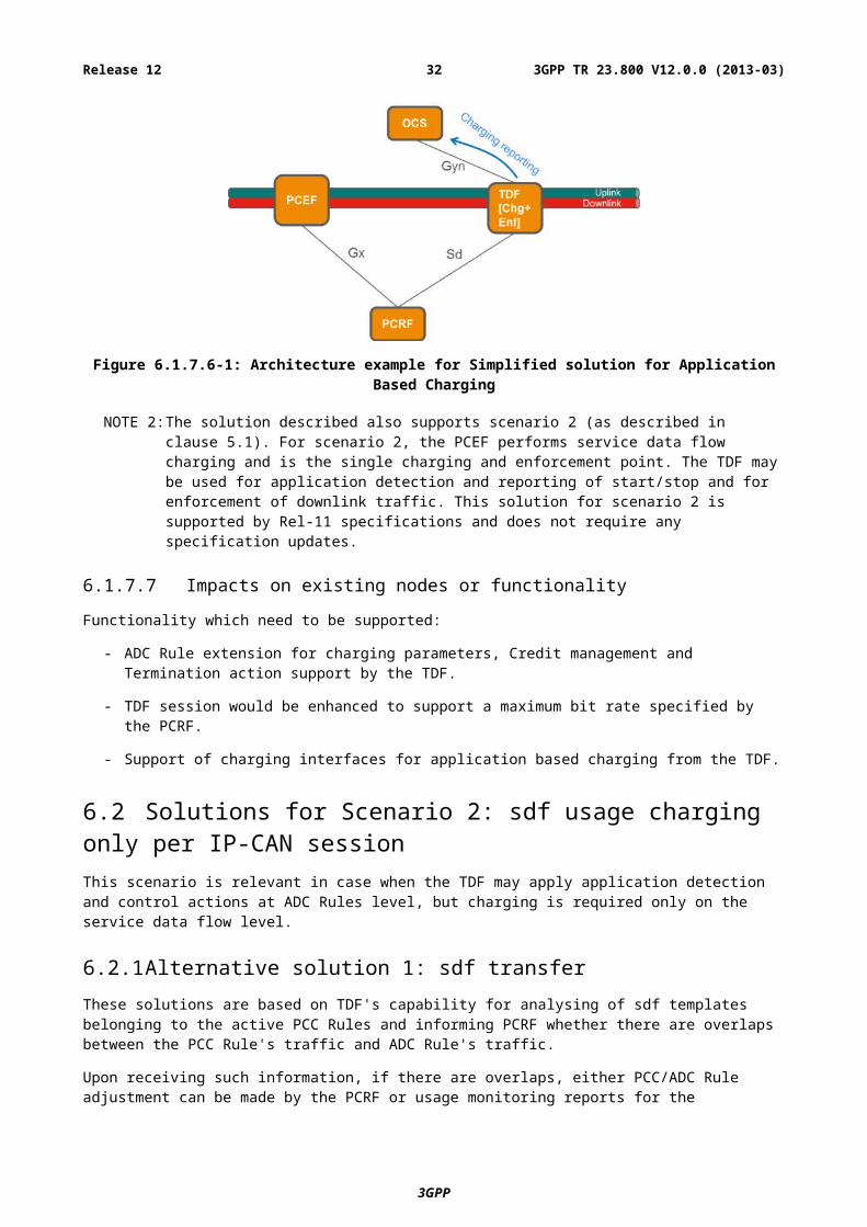
For scenario 1 the TDF is the single point of charging and policy enforcement for the IP-CAN session. The ADC rules are used to determine the online and offline characteristics. For offline charging, usage reporting over the Gzn interface will be used. For online charging, credit management and reporting over the Gyn interface will be used. The PCEF is in this case not used for charging and enforcement (based on active PCC rules and APN-AMBR configuration), but will still be performing bearer binding based on the active PCC rules. In addition, the DL APN-AMBR in PCEF need to be configured with such high values that it does not result in discarded packets.
NOTE 1: The PCEF may still do enforcement of uplink traffic without impacting the accuracy of the charging information produced by the TDF.
This is illustrated for online charging only in the following figure.
Figure 6.1.7.6-1: Architecture example for Simplified solution for Application Based Charging
3GPP
3GPP TR 23.800 V12.0.0 (2013-03)25Release 12
NOTE 2: The solution described also supports scenario 2 (as described in clause 5.1). For scenario 2, the PCEF performs service data flow charging and is the single charging and enforcement point. The TDF may be used for application detection and reporting of start/stop and for enforcement of downlink traffic. This solution for scenario 2 is supported by Rel-11 specifications and does not require any specification updates.
6.1.7.7 Impacts on existing nodes or functionality
Functionality which need to be supported:
- ADC Rule extension for charging parameters, Credit management and Termination action support by the TDF.
- TDF session would be enhanced to support a maximum bit rate specified by the PCRF.
- Support of charging interfaces for application based charging from the TDF.
6.2 Solutions for Scenario 2: sdf usage charging only per IP-CAN sessionThis scenario is relevant in case when the TDF may apply application detection and control actions at ADC Rules level, but charging is required only on the service data flow level.
6.2.1 Alternative solution 1: sdf transfer
These solutions are based on TDF's capability for analysing of sdf templates belonging to the active PCC Rules and informing PCRF whether there are overlaps between the PCC Rule's traffic and ADC Rule's traffic.
Upon receiving such information, if there are overlaps, either PCC/ADC Rule adjustment can be made by the PCRF or usage monitoring reports for the overlapping sdf templates can be provided by the TDF->PCRF->PCEF in order to apply charging accurately.
Volume / time / time & volume / event based charging:
As PCEF performs policy control for sdf, the alternative solution (Scenario 2, Solution 1), proposed for this scenario, is such that PCEF performs also charging, controlled by the PCRF by providing charging control parameters within the PCC Rules. In this case, the PCEF shall be the only charging reporting entity. The PCEF shall gather information for uplink and for downlink, and, in case it is requested as per PCC Rule, received from the PCRF, shall establish session with OCS/OFCS and provide charging information per service data flows according to TS 23.203 [3].
a. In the downlink direction, as PCEF's enforcement actions happen after any possible enforcement action applied by the TDF at the detected application's level, the charging reports are accurate. Therefore, accurate calculations are done by the PCEF.
b. In case PCC Rule's traffic and application traffic flows are independent of each other in the uplink direction and this is known in advance, then also no correlation needs to be made, even if application control is applied at the TDF for application's traffic (Scenario 2, Solution 1, Case 2-a). Therefore, an accurate charging report is achieved by reporting as per charging parameters provided within PCC Rule. However, if such an assumption can't be made, then the following technical issue need to be resolved in order to provide accurate charging reports. In the uplink direction, the TDF may perform enforcement actions after the traffic passes through the
3GPP
3GPP TR 23.800 V12.0.0 (2013-03)26Release 12
PCEF. In case the service data flows are also enforced by the TDF in the uplink direction as a part of application's traffic, it needs to be assured that PCEF reports for those service data flows accurately.
i. The PCRF shall provide to the TDF all sdf templates which are part of active PCC Rules and need to be reported for charging in the uplink direction. The PCRF shall provide the sdf templates with an indication of their (relative) precedence following the precedence of the corresponding PCC Rules they belong to. The TDF upon application detection shall perform the comparison of the sdf templates and the detected application's traffic in the same order as received from the PCRF. Every time a new IP flows belonging to the application are detected, such a comparison shall be implemented.
NOTE 1: Case of APN-AMBR enforcement by the PCEF is not supported by this solution.
ii. If those reported sdf templates don't belong to any of the application (s), then there is no need in the correlation (Scenario 2, Solution 1, Case 2-b).
iii. If those sdf templates also belong to the application (s) which is enforced in the uplink direction (Scenario 2, Solution 1, Case 2-c), then the TDF shall inform the PCRF by providing those sdf templates belonging to application with their enforcement action/or indication which ADC Rule (s) they belong to. In case there are some IP flows of that sdf template that do not belong to the application, the TDF shall also separately report about those IP flows (e.g. by providing the corresponding sdf template which was previously received from the PCRF and under this providing a list of only those IP flows which belong to the application).
- (Scenario 2, Solution 1-a, Case 2-c) The PCRF then may adjust enforcement and charging model for PCEF by e.g. creating a new PCC rule (s) for those sdf templates with a higher priority and e.g. having zero charging in case of redirection, adjusting bandwidth limitation of those sdf templates to the values provided to the TDF per application which include those sdf templates etc.
NOTE 2: In case the same IP-5-tuple is shared by application's traffic and other traffic in the uplink direction, all "non-application traffic" (fitting to the IP-5-tuple) would have to be enforced in the same way as the application traffic.
- (Scenario 2, Solution 1-b, Case 2-c) Alternatively, the PCRF may ask the TDF to provide usage monitoring report (through PCRF, PCRF then transfer it to the PCEF) about those service data flow usage by providing a separate PCC Rules with a higher precedence in order to get usage monitoring only for that sub-set of the overlapping sdf templates out of the PCC Rules overall usage. Thus, the PCEF can have accurate information about the usage and report to the OCS/OFCS in such a way that the reports are accurate and an accurate charging is performed by the PCEF.
Editor's note: The efficiency of this solution as well as timescale synchronization for requesting such reports between PCEF-PCRF-TDF and the charging report to OCS/OFCS and also gaps which needs to be filled in order to achieve credit management functionality in the system is FFS. PCRF mechanisms for PCC Rules' adjustment in case of additional PCC Rules created for usage monitoring reports of an overlapping sdf templates are FFS.
NOTE 3: There is assumption here that the same IP-5-tuple is not shared by application's traffic and other traffic in the uplink direction, otherwise PCEF may not have relevant knowledge on how to count.
6.2.1.4 Impacts on existing nodes or functionality
Table 6.2.1.4
Scenario 2, Solution 1, Case 2-a
Scenario 2, Solution 1, Case 2-b
Scenario 2, Solution 1-a, Case 2-c
Scenario 2, Solution 1-b, Case 2-c
No overlapping traffic for PCC and ADC Rules and it is known in advance
No overlapping traffic for PCC and ADC Rules as a result of sdf templates comparison performed by the TDF
There are overlapping sdf templates, PCC/ADC Rule adjustments are performed by the PCRF
There are overlapping sdf templates, usage monitoring reports correlations are used between the PCEF and the TDF
Additional functionality which need to be supported:
- (Scenario 2, Solution 1, Case 2-a) - no additional functionality required
3GPP
3GPP TR 23.800 V12.0.0 (2013-03)27Release 12
- (Scenario 2, Solution 1, Case 2-b)
- PCRF is responsible to transfer sdf templates of active PCC Rules to the TDF in accordance with their precedence.
- TDF is responsible to compare and verify whether received sdf templates belong to the detected application traffic and inform PCRF about the result.
- (Scenario 2, Solution 1-a, Case 2-c)
- As (Scenario 2, Solution 1, Case 2-b) and additionally:
- PCRF is responsible for adjusting rules based on the information received.
- (Scenario 2, Solution 1-b, Case 2-c)
- As (Scenario 1, Solution 1, Case 2-b) and additionally:
- PCRF is responsible to create new ADC Rules for those sdf templates which belong also to the application and ask usage monitoring report for those rules; then transfer those usage monitoring reports to the PCEF.
- Upon receiving this information, PCEF is responsible to align the uplink usage information for the sdf templates.
6.2.2 Alternative solution 2: Sy extension
In this solution, for some particular traffic handling case, mentioned in the assumption below, Sy interface is enhanced so the PCRF can correlate the information received for PCC and for ADC Rules and report to the OCS by using Sy.
6.2.2.1 Solutions' assumptions
1. All of the application's traffic specified by an ADC Rule's is contained within the traffic described by sdf templates of a single PCC Rule / or if bearer level charging is applied at the PCEF (thus ADC Rule is also sub-part of the whole report).
Editor's Note: This may match only some of traffic handling cases e.g. when PCC Rule measures the whole IP-CAN session/whole bearer traffic. Additional examples of traffic handling cases for this solution are FFS.
2. Only online charging is supported.
6.2.2.2 Reference architecture
As defined by TS 23.203 [3] except that Gy/Gz interfaces are not needed as Gy functionality is replaced by Sy interface and there is no offline charging.
6.2.2.3 Reporting, Credit management and termination action
These actions shall be defined over Sy interface.
Editor's Note: The precise definition of the functionalities in the PCRF required to implement these functions is FFS.
6.2.2.4 Functional description
- Both PCEF and TDF provide simultaneous usage monitoring reports to the PCRF;
- Then PCRF may perform the adjustment so that all the traffic identified by the PCC rule minus the traffic identified by the ADC Rules is reported to the OCS by introducing enhancements to Sy interface;
Editor's Note: The required Sy enhancements in order to support this solution as well as efficiency and complexity of this solution are FFS.
3GPP
3GPP TR 23.800 V12.0.0 (2013-03)28Release 12
6.2.2.5 Impacts on existing nodes or functionality
Additional functionality which need to be supported:
- PCRF has to support credit management and termination action functionality.
- PCRF has to support alignment (subtracting) between the PCEF and the TDF reports.
- Sy interface has to be enhanced in order to provide charging reports, credit management and termination action.
- OCS has to support requesting and receiving charging reports from the PCRF.
6.2.3 Alternative solution 3: TDF marking and PCEF based application charging
See clause 6.1.3.3 for the functional description.
There are two small differences in this solution (compared to the description in clause 6.1.3.3) due to the fact that only SDF charging is performed:
- When the PCRF generates the PCC rule for the application traffic which is marked by the TDF, the PCRF copies the control information for charging (and usage monitoring) of the PCC rule containing the match-all filter.
- The PCEF performs the charging for the PCC rule(s) for application traffic and the PCC rule containing the match-all filter in a combined way (i.e. by a common gathering of usage information and/or credit management) so that the charging systems are not impacted.
For variant c), the TDF manages separate counters for the dropped and redirected application traffic and provides their values to the PCEF on a regular basis. The PCEF corrects the uplink counter of the match-all PCC rule by the sum of all counter values. For scenarios wherein application traffic is transferred via a different PCC rule, the PCEF instead corrects the corresponding PCC rule which handled the application traffic in uplink direction. Unless the PCRF indicates a specific PCC rule, the PCEF uses the lowest precedence PCC rule of the bearer on which the uplink application traffic was received.
6.2.3.4 Impacts on existing nodes or functionality
See clause 6.1.3.4 for the impacts on existing nodes or functionality.
In addition, the PCEF is required to perform the charging for the PCC rule(s) for application traffic and the PCC rule containing the match-all filter in a combined way. For scenarios wherein application traffic is transferred via a different PCC rule, the PCEF instead combines the charging for the application specific PCC rule with the corresponding PCC rule which handled the application traffic in uplink direction.
For variant c), the TDF is required to apply separate counters for the dropped and redirected application traffic and to provide their values to the PCEF on a regular basis.
For variant c), the PCEF is required to correct the uplink counter of the PCC rule which handled the application traffic in uplink direction according to the sum of all received TDF counter values.
3GPP
3GPP TR 23.800 V12.0.0 (2013-03)29Release 12
6.2.4 Alternative solution 4: Bi-Directional Marking of Charged Packets
6.2.4.1 Solution assumptions
See clause 6.3.5.1 for a list of assumptions.
6.2.4.2 Reference architecture
As defined in clause 6.3.1.2.
6.2.4.3 Functional description
In Scenario 2, only service data flow charging is required. This scenario is relevant in the case where the TDF may apply application detection and control actions at ADC Rules level, but charging is required only on the service data flow level.
The description outlined in section 6.3.5 is applicable in this case. The call flow outlined in section 6.3.5.4 is applicable with the following exceptions:
- Steps 7, 8, 15 and 16 are not applicable.
- Refunds are not required in step 17
- Steps 12, 13, 19 and 20 are only used to pass refund information from the TDF to the OCS (it is assumed that the TDF to OCS session starts when the first refund case is detected at step 12).
- If no refunds are necessary, then these steps are not applicable either (and no TDF to OCS session is required).
6.2.5 Alternative solution 5: TDF TFT analysis
This solution is based on TDF's capability for analysing of sdf templates belonging to the active PCC Rules and reporting to OCS whether there are some traffic is discarded according to ADC rules which already pass and charging by PCEF.
6.2.5.1 Solutions' assumptions
As defined in clause 6.1.5.1.
6.2.5.2 Reference architecture
As defined in clause 6.1.5.2.
6.2.5.3 PCC rule extension
As defined in clause 6.3.6.3.
6.2.5.4 ADC rule extension
As defined in clause 6.3.6.4.
6.2.5.5 Termination Action
As defined in clause 6.1.5.4.
6.2.5.6 Functional description
As PCEF performs detection and enforcement of the sdf, the alternative proposal is that PCEF performs also charging for the sdf, controlled by the PCRF by providing charging control parameters within PCC Rules. The PCEF shall gather
3GPP
3GPP TR 23.800 V12.0.0 (2013-03)30Release 12
information for uplink and for downlink, and, in case it is requested as per PCC Rule, received from the PCRF, shall establish session with OCS/OFCS and provide charging information per sdf.
- In the downlink direction, as PCEF's enforcement actions happen after any possible enforcement action applied by the TDF at application level, the charging reports are accurate. Therefore, accurate calculations are done by the PECF.
- In the uplink direction, the TDF may perform enforcement actions after the traffic passes through the PCEF. In that case, some service data flow which will be possibly discarded by TDF already count by PCEF when reporting sdf traffic to OCS. To ensure the traffic OCS get known of is accurate when charging:
- PCRF provide TDF the ADC rules as defined in TS 23.203 [3] in addition with the sdf template which is a part of PCC rules. In the case of PCC rules not known by PCRF, PCEF shall provide bear identifier and corresponding sdf templates over Gx interface. The extended ADC rules shall also include a correlation identifier which is also provided from PCRF to PCEF to correlate the charging session from PCEF and from TDF between OCS and the precedence, the flow charging key which are parts of the corresponding PCC Rules they belong to as well.
- PCRF provide PCEF the PCC rules as defined in TS 23.203 [3] in addition with a correlation identifier which is also provided from PCRF to PCEF to correlate the charging session from PCEF and from TDF between OCS.
- When a new IP flow belonging to the detected application and it shall be discarded by TDF according to the ADC rule, TDF analyses the sdf templates of the extended ADC rules and compare it with the detected application traffic in the order as indicated by the precedence of the ADC rules which following the precedence of corresponding PCC rules. In case the comparison is successful, the TDF shall count accumulation and report to OCS with the correlation identifier, flow charging key and a special charging key e.g. zero charging. This special charging key means to OCS that the traffic is discarded however possibly counted in usage report from some CTFs.
- After receiving the charging report from PCEF and the discarded traffic report from TDF, the OCS shall:
- If a charging session from PCEF and a charging session initiated by TDF has same correlation identifier, take these sessions are for the IP-CAN bearer and the application traffic which combining with it
- For the charging sessions are correlated in previous step, consider the traffic of the PCEF charging report minus the traffic of the correlative TDF discarded traffic report as the actual service data flow's traffic if the flow charging key in charging reports are same.
6.2.5.7 Impacts on existing nodes or functionality
- PCC rule extension to delivery charging session correlation ID
- ADC Rules extension for charging parameters and the sdf template, precedence, gate status etc. for detection whether a packet will be discarded in PCEF
- PCEF support transfer charging session correlation identifier with addition via Gy interface.
- TDF support report discarded traffic according to extended ADC rule, to OCS via new Gyn interface.
- OCS support receiving discarded traffic report from TDF.
NOTE: The OCS has to take the possibility of outstanding reports for discarded traffic into account when user balance is getting low.
6.2.6 Alternative solution 6: Returning the dropped packet
6.2.6.1 Solutions' assumption
None.
3GPP
3GPP TR 23.800 V12.0.0 (2013-03)31Release 12
6.2.6.2 Reference architecture
As defined by the TS 23.203 [3].
6.2.6.3 Functional description
In Scenario 2, only service data flow charging is required. This scenario is relevant in the case where the TDF may apply application detection and control actions at ADC Rules level, but charging is required only on the service data flow level.
The description outlined in clause 6.3.7.3.2 is applicable in this case.
6.2.6.4 Mechanisms of tunnelling
For this solution, the returned packet will be encapsulated in the IP tunnel. The possible tunnel mechanism can be referred to Annex B.
6.3 Solutions for Scenario 3: Both service data flow charging and application usage charging is required per IP-CAN sessionThis scenario is relevant in case when the TDF may apply application control actions on ADC Rules level, and PCEF may apply policy control on PCC Rules level, and charging is required both on the service data flow and on the application level.
6.3.1 Alternative solution 1: sdf transfer
These solutions are based on TDF's capability for analysing of sdf templates belonging to the active PCC Rules and informing PCRF whether there are overlaps between the PCC Rule's traffic and ADC Rule's traffic.
Upon receiving such information, if there are overlaps, either PCC/ADC Rule adjustment can be made by the PCRF or usage monitoring reports for the overlapping sdf templates can be provided by the PCEF<->PCRF<->TDF in order to apply charging accurately.
6.3.1.1 Solutions' assumptions
Same assumptions as defined by clause 6.1.1.1.
3GPP
3GPP TR 23.800 V12.0.0 (2013-03)32Release 12
6.3.1.2 Reference architecture
Figure 6.3.1.2-1
Editor's note: It is FFS whether Gyn/Gzn is Gy/Gz or an enhancement of Gy/Gz. Whether the Gyn/Gzn is to be renamed is FFS.
6.3.1.3 Application Detection and Control Rule extension
Same as defined by clause 6.1.1.3.
6.3.1.4 Credit management
Credit management for TDF online charging report shall be as defined by clause 6.1.1.4.
Credit management for PCEF online charging report shall be as defined by TS 23.203 [3].
The credit management for the PCEF and the TDF shall be synchronized by the OCS.
Editor's Note: Further credit management requirements with regard to multiple charging points are FFS.
6.3.1.5 Termination Action
The termination action for TDF online charging report shall be as defined by clause 6.1.1.5.
The termination action for PCEF online charging report shall be as defined by TS 23.203 [3].
The Termination action applied at the TDF and at the PCEF shall be coordinated by the OCS.
6.3.1.5a Reporting
Reporting for TDF offline and online charging shall be as defined by clause 6.1.1.5a.
3GPP
3GPP TR 23.800 V12.0.0 (2013-03)33Release 12
Reporting for PCEF offline and online charging shall be as defined by TS 23.203 [3].
6.3.1.6 Functional Description
Volume / time / time & volume / event based charging:
The alternative (Scenario 3, Solution 1), proposed for this scenario, is that both PCEF and TDF perform also charging, controlled by the PCRF by providing charging control parameters within PCC/ADC Rules. In this case, the PCEF and the TDF shall be both charging reporting entities. The PCEF and the TDF shall gather information for uplink and for downlink, and, in case it is requested as per PCC Rules and per ADC Rules, received from the PCRF, shall establish session with OCS/OFCS and provide charging information.
- In case PCC Rule's traffic and application traffic flows are independent of each other in both uplink and downlink direction and this is known in advance, then no correlation needs to be made (Scenario 3, Solution 1, Case 2-a). Therefore, an accurate charging report is achieved by reporting as per charging parameters provided within ADC and PCC Rules. However, if such an assumption can't be made, then the following technical issues need to be resolved in order to provide accurate charging reports:
- In the uplink direction, the TDF may perform enforcement actions after the traffic passes through the PCEF. In case the sdf templates are also enforced by the TDF in the uplink direction as a part of application's traffic, it needs to be assured that PCEF reports for those sdf templates accurately.
- In the downlink direction, the PCEF may perform enforcement actions after the traffic passes through the TDF. In case the sdf template enforced by the PCEF in the downlink also belong to the application which needs to be reported for charging, it needs to be assured that the TDF reports for the application accurately.
- In order to assure this:
i. The PCRF shall provide to the TDF all sdf templates which are part of active PCC Rules. The PCRF shall provide the sdf templates with an indication of their (relative) precedence following the precedence of the corresponding PCC Rules they belong to. The TDF upon application detection shall perform the comparison of the sdf templates and the detected application's traffic in the same order as received from the PCRF. Every time a new IP flows belonging to the application are detected, such a comparison shall be implemented.
NOTE 1: Case of APN-AMBR enforcement by the PCEF is not supported by this solution.
ii. If those reported sdf templates doesn't belong to any of the application (s), which need to be reported for charging, then there is no need in the correlation (Scenario 3, Solution 1, Case 2-b). The charging is therefore can be applied per all PCC and ADC Rules provided.
iii. The solutions for the non-affected additional PCC and ADC Rules for the same IP-CAN session are also provided as per PCC and ADC Rules charging parameters without any correlation needed.
iv. If some of those sdf templates also belong to the detected application (s), which need to be enforced and/or charged per ADC Rule, then
A. (Scenario 3A) In the uplink direction, in case TDF performs enforcement actions but don't need to charge per this specific application, the solutions for the affected PCC Rules shall be the same as described for (Scenario 2);
B. (Scenario 3B) In the downlink direction, in case the PCEF performs enforcement actions per PCC Rules with the affected sdf templates, but don't need to charge per those specific sdf templates, the solutions for the affected ADC Rules shall be the same as described for (Scenario 1);
C. In the uplink direction, in case TDF performs enforcement actions and need to charge per this specific application,
- In order to correlate for the impacted sdf templates, the TDF shall inform the PCRF by providing those sdf templates belonging to the enforced/to be charged application with their enforcement action/or indication which ADC Rule (s) they belong to. In case there are some IP flows of that sdf template that do not belong to the application, the TDF shall also separately report about those IP flows (e.g. by providing the corresponding sdf template which was previously received from the PCRF and under this providing a list of only those IP flows which belong to the application).
3GPP
3GPP TR 23.800 V12.0.0 (2013-03)34Release 12
- (Scenario 3C, Solution 1, Case 2-c) The PCRF then may adjust enforcement and charging model for PCEF by e.g. creating a new PCC rule (s) for those sdf templates with a higher priority and e.g. having zero charging in case of redirection, adjusting bandwidth limitation of those sdf templates to the values provided to TDF per application which include those sdf templates etc.
NOTE 2: In case the same IP-5-tuple is shared by application's traffic and other traffic in the uplink direction, all "non-application traffic" (fitting to the IP-5-tuple) would be enforced in the same way as the application traffic. Additional point to consider while evaluating solutions is if this solution is quick and efficient enough for short-lived IP flows and thus is able to address key issue 1.
- (Scenario 3C, Solution 1, Case 2-d) Alternatively, the PCRF then may ask the TDF to provide usage monitoring report (through PCRF to the PCEF) about those service data flow usage by providing a separate ADC Rules in order to get usage monitoring only for that sub-set of the overlapping sdf templates. The PCRF may need to adjust the PCC Rules' enforcement actions based on this. Thus, the PCEF can have accurate information about the usage and report to the OCS/OFCS in such a way that the reports are accurate.
Editor's note: The efficiency of this solution as well as timescale synchronization for requesting such reports between PCEF-PCRF-TDF and the charging report to OCS/OFCS and also gaps which needs to be filled in order to achieve credit management functionality in the system is FFS. PCRF mechanisms for PCC Rules' adjustment in case of additional PCC Rules created for usage monitoring reports of an overlapping sdf templates are FFS.
NOTE 3: There is assumption here that the same IP-5-tuple is not shared by application's traffic and other traffic in the uplink direction; otherwise PCEF may not have relevant knowledge on how to count.
- Additionally, the PCRF shall also signal to the TDF if those sdf templates should be counted for application's charging or not ('not' means that this would be counted within PCC Rule only). This indication may also be part of ADC Rule. If those sdf templates have to be excluded from TDF's counting per application, then the TDF shall provide application's usage charging for all accumulated traffic excluding sdf templates which are reported by PCC Rules. In such a case, a corresponding indication should also be provided to the OCS.
D. In the downlink direction, in case PCEF performs enforcement actions and need to charge per these specific affected sdf templates:
- In order to correlate for the impacted sdf templates, the TDF shall inform the PCRF by providing those sdf templates belonging to the enforced application with their enforcement action/or indication which ADC Rule (s) they belong to. In case there are some IP flows of that sdf template that do not belong to the application, the TDF shall also separately report about those IP flows (e.g. by providing sdf template and under this providing a list of only those IP flows which belong to the application).
- (Scenario 3D, Solution 1, Case 2-e) The PCRF may ask the PCEF to provide usage monitoring report (through the PCRF back to the TDF) about those service data flow usage by providing a separate PCC Rules with a higher precedence in order to get usage monitoring only for that sub-set of the overlapping sdf templates out of the PCC Rules overall usage. The PCRF may need to adjust the PCC Rules' enforcement actions based on this. Thus, the TDF can have correct information about usage and report to OCS/OFCS in such a way that the reports are accurate and no over-charging is performed.
Editor's note: The efficiency of this solution as well as timescale synchronization for requesting such reports between PCEF-PCRF-TDF and the charging report to OCS/OFCS and also gaps which needs to be filled in order to achieve credit management functionality in the system is FFS. PCRF mechanisms for PCC Rules' adjustment in case of additional PCC Rules created for usage monitoring reports of an overlapping sdf templates are FFS.
NOTE 4: There is assumption here that the same IP-5-tuple is not shared by application's traffic and other traffic in the downlink direction; otherwise the TDF may not have relevant knowledge on how to count.
- Alternatively (Scenario 3D, Solution 1, Case 2-f), the PCRF may adjust ADC Rules for the application in the downlink direction, if appropriate, to match the same enforcement action as defined for the PCC Rules for the sdf templates, belonging to the detected application.
NOTE 5: In case the same IP-5-tuple is shared by application's traffic and other traffic in the downlink direction, and bandwidth limitation enforcement action is applied in the downlink direction, the TDF may not have relevant knowledge on how to count.
3GPP
3GPP TR 23.800 V12.0.0 (2013-03)35Release 12
- Optionally, additionally, the PCRF may also signal to the TDF if those sdf templates should be counted for application's charging or not ('not' means that this would be counted within PCC Rule only). This indication may also be part of ADC Rule. If those sdf templates have to be excluded from TDF's counting per application, then the TDF shall provide application's usage charging for all accumulated traffic excluding sdf templates which are reported by PCC Rules. In such a case, a corresponding indication should be provided to the OCS.
6.3.1.7 Impacts on existing nodes or functionality
Table 6.3.1.7-1
Scenario 3, Solution 1, Case 2-a
Scenario 3, Solution 1, Case 2-b
Scenario 3A Scenario 3B
No overlapping traffic for PCC and ADC Rules and it is known in advance
No overlapping traffic for PCC and ADC Rules as a result of sdf templates comparison performed by the TDF
There are overlapping sdf templates. In the uplink direction, in case TDF performs enforcement actions but don't need to charge per this specific application, the solutions for the affected PCC Rules shall be the same as described for (Scenario 2)
There are overlapping sdf templates. In the downlink direction, in case the PCEF performs enforcement actions per PCC Rules with the affected sdf templates, but don't need to charge per those specific sdf templates, the solutions for the affected ADC Rules shall be the same as described for (Scenario 1)
Table 6.3.1.7-2
Scenario 3C, Solution 1, Case 2-c
Scenario 3C, Solution 1, Case 2-d
Scenario 3D, Solution 1, Case 2-e
Scenario 3D, Solution 1, Case 2-f
There are overlapping sdf templates, PCC/ADC Rule adjustments are performed by the PCRF
There are overlapping sdf templates, usage monitoring reports correlations are used between the PCEF and the TDF
There are overlapping sdf templates, usage monitoring reports correlations are used between the PCEF and the TDF
There are overlapping sdf templates, PCC/ADC Rule adjustments are performed by the PCRF
Functionality which need to be supported:
- ADC Rule extension for charging parameters, Credit management and Termination action support by the TDF, support of charging interfaces from the TDF
- (Scenario 3, Solution 1, Case 2-a) - no additional functionality required
- (Scenario 3, Solution 1, Case 2-b)
- PCRF is responsible to transfer sdf templates of active PCC Rules to the TDF in accordance with their precedence.
- TDF is responsible to compare and verify whether received sdf templates belong to the detected application traffic and inform PCRF about the result.
- (Scenario 3A)
- As (Scenario 3, Solution 1, Case 2-b) and additionally:
- Either
- PCRF is responsible for adjusting rules based on the information received.
- Or
3GPP
3GPP TR 23.800 V12.0.0 (2013-03)36Release 12
- PCRF is responsible to create new ADC Rules for those sdf templates which belong also to the application and ask usage monitoring report for those rules; then transfer those usage monitoring reports to the PCEF.
- Upon receiving this information, PCEF is responsible to align the uplink usage information for the sdf templates.
- (Scenario 3B)
- As (Scenario 3, Solution 1, Case 2-b) and additionally:
- Either
- PCRF is responsible to create new PCC Rules with higher precedence for those sdf templates which belong also to the application and ask usage monitoring report for those rules; then transfer those usage monitoring reports to the TDF.
- Upon receiving this information, TDF is responsible to align the downlink usage information for the detected application.
- Or
- PCRF is responsible for adjusting rules based on the information received.
- (Scenario 3C)
- As (Scenario 3, Solution 1, Case 2-b) and additionally:
- Either
- PCRF is responsible for adjusting rules based on the information received.
- Or
- PCRF is responsible to create new ADC Rules for those sdf templates which belong also to the application and ask usage monitoring report for those rules; then transfer those usage monitoring reports to the PCEF.
- Upon receiving this information, PCEF is responsible to align the uplink usage information for the sdf templates.
- Additionally, PCRF is responsible to indicate where (at TDF or at PCEF) overlapping sdf templates should be counted towards charging reports.
- (Scenario 3D)
- As (Scenario 3, Solution 1, Case 2-b) and additionally:
- Either
- PCRF is responsible to create new PCC Rules with higher precedence for those sdf templates which belong also to the application and ask usage monitoring report for those rules; then transfer those usage monitoring reports to the TDF.
- Upon receiving this information, TDF is responsible to align the downlink usage information for the detected application.
- Or
- PCRF is responsible for adjusting rules based on the information received.
- Additionally, PCRF is responsible to indicate where (at TDF or at PCEF) overlapping sdf templates should be counted towards charging reports.
3GPP
3GPP TR 23.800 V12.0.0 (2013-03)37Release 12
6.3.2 Alternative solution 2: Sy extension
In this solution, for some particular traffic handling cases, mentioned in the assumption below, Sy interface is enhanced so the PCRF can correlate the information received for PCC and for ADC Rules and report to the OCS by using Sy.
6.3.2.1 Solutions' assumptions
1. In the uplink direction, all of the application's traffic specified by an ADC Rule's is contained within the traffic described by sdf templates of a single PCC Rule / or if bearer level charging is applied at the PCEF (thus ADC Rule is also sub-part of the whole report).
2. In the downlink direction, all of the traffic described by sdf templates of all PCC rules is contained within the traffic of an application specified by an ADC rule.
Editor's Note: The specific examples of traffic handling cases for this solution are FFS.
3. Only online charging is supported.
6.3.2.2 Reference architecture
As defined by the TS 23.203 [3] except that Gy/Gz interfaces are not needed as Gy functionality is replaced by Sy interface and there is no offline charging.
6.3.2.3 Reporting, Credit management and termination action
These actions shall be defined over Sy interface.
Editor's Note: The precise definition of the functionalities in the PCRF required to implement these functions is FFS.
6.3.2.4 Functional description
- Both PCEF and TDF provide simultaneous usage monitoring reports to the PCRF;
- Then PCRF may perform the adjustment so that:
i. For the uplink sdf based charging, all the traffic identified by the PCC rule minus the traffic identified by the ADC Rules is reported to the OCS.
ii. For the uplink application based charging, ADC Rule's consumed credit is reported to the OCS.
iii. For the downlink application based charging, all the traffic identified by the ADC rule minus the traffic identified by the PCC Rules is reported to the OCS.
iv. For the downlink sdf based charging, PCC Rule consumed credit is reported to the OCS.
By introducing enhancements to Sy interface.
NOTE: The reports depend on PCRF's decision on whether overlapping sdf templates should be counted for sdf or for application based charging.
Editor's Note: The required Sy enhancements in order to support this solution as well as efficiency and complexity of this solution are FFS.
6.3.2.5 Impacts on existing nodes or functionality
Additional functionality which need to be supported:
- PCRF has to support credit management and termination action functionality.
- PCRF has to support alignment (subtracting) between the PCEF and the TDF reports.
- Sy interface has to be enhanced in order to provide charging reports, credit management and termination action.
3GPP
3GPP TR 23.800 V12.0.0 (2013-03)38Release 12
- OCS has to support requesting and receiving charging reports from the PCRF.
6.3.3 Alternative solution 3: Correlation by OCS
In this solution, for some particular traffic handling case, mentioned in the assumption below, OCS receives reports from the PCEF and from the TDF and adjusts them so overall charging is performed accurately.
Same as defined for Scenario 3 Solutions 1 (clauses 6.3.1.2 - 6.3.1.5) without Gz/Gzn.
6.3.3.3 Functional description
The OCS may request simultaneous credit re-authorization triggers from both PCEF and TDF, and perform credit and eventually charging adjustments so that:
- For the uplink sdf based charging, the credit allocated to the PCEF is what requested by the PCEF , but the charging on the OCS only considers the credit requested minus the credit allocated to the ADC rule for that application's traffic.
- For the uplink application based charging, ADC Rule's consumed credit is considered by the OCS.
- For the downlink application based charging, the credit allocated to the TDF is what requested by the TDF, but the charging on the OCS only considers the credit requested minus the credit allocated to the PCC Rule.
- For the downlink sdf based charging, PCC Rule consumed credit is considered by the OCS.
NOTE: The calculations depend on decision on whether overlapping sdf templates should be counted for sdf or for application based charging.
6.3.3.4 Impacts on existing nodes or functionality
- ADC Rule extension for charging parameters, Credit management and Termination action support by the TDF, support of charging interfaces from the TDF.
- Adjustment of reports implemented by the OCS so charging is performed accurately.
6.3.4 Alternative solution 4: TDF marking and PCEF based application charging
See clause 6.1.3.3 for the functional description.
For variant c), the TDF manages separate counters for the forwarded, dropped and redirected application traffic and provides their values to the PCEF on a regular basis. The PCEF updates the uplink counter of the application specific
3GPP
3GPP TR 23.800 V12.0.0 (2013-03)39Release 12
PCC rule according to the counter values for the forwarded and redirected traffic. In addition, the PCEF corrects the uplink counter of the match-all PCC rule by the sum of all counter values. For scenarios wherein application traffic is transferred via a different PCC rule, the PCEF instead corrects the corresponding PCC rule which handled the application traffic in uplink direction. Unless the PCRF indicates a specific PCC rule, the PCEF uses the lowest precedence PCC rule of the bearer on which the uplink application traffic was received.
6.3.4.4 Impacts on existing nodes or functionality
See clause 6.1.3.4 for the impacts on existing nodes or functionality.
For variant c), the TDF is required to apply separate counters for the forwarded, dropped and redirected application traffic and to provide their values to the PCEF on a regular basis (variant c) only).
For variant c), the PCEF is required to correct in addition the uplink counter of the PCC rule which handled the application traffic in uplink direction according to the sum of all received TDF counter values (variant c) only).
6.3.5 Alternative solution 5: Bi-Directional Marking of Charged Packets
6.3.5.1 Solution assumptions
The following assumptions are made for this solution:
- Any packet marking scheme already in use in a mobile network should not be invalidated.
- It is assumed that any network equipment in between the PCEF and the TDF (e.g. routers) do not modify the packet marking mechanism applied.
As defined in clause 6.3.1.2, 6.3.1.3, 6.3.1.4 and 6.3.1.5, 6.3.1.5a.
Editor's Note: This solution requires additional capabilities that are FFS.
6.3.5.3 Functional description
In the packet-marking mechanism, the first enforcement point marks the packets that it is charging for so that the second enforcement point is aware of what packets have already been charged for.
The mechanisms described are equally applicable for offline charging as well as online charging. The OFCS will need to correlate and process refunds that it receives in the same manner as described for the OCS. This will require additional functionality in the OFCS
3GPP
3GPP TR 23.800 V12.0.0 (2013-03)40Release 12
Figure 6.3.5.3-1
The figure above illustrates an example of how the scheme works for online charging. In this example, four packets (A, B, C, and D) are received by the TDF in the downlink direction. In the process of applying the layer 7 Application Detection and Control (ADC) rules, it does not block any packets, and decides to charge for packets A, B and C. Packets A and B belong to the same application and are charged for using the charging identifier X. Packet C is charged for using the charging identifier Y. The TDF has an active online charging session with the OCS and so reports the relevant charging information to the OCS.
As the TDF does not block any packets, all of them (A, B, C and D) continue on to the PCEF. The TDF uses one of the packet marking mechanisms outlines in clause 6.3.5.8 in order to mark the packets that it has charged for, along with an associated charging identifier. In this case that means that packets A and B are marked with charging identifier X and packet C is marked with charging identifier Y. The charging identifier is customisable, and there may be a single charging identifier to identify all charged for packets, or a more granular mechanism with multiple charging identifiers.
The PCEF receives the data from the TDF (including the market packet information). Through the process of implementing the PCC rules, the PCEF enforces a rule which results in packet A being dropped, and let packets B, C and D through. As it knows that the TDF has previously charged for packet A (as it is marked with charging identifier X), the PCEF now knows that there has been a packet that was charged for by the TDF that is about to be dropped.
The PCEF also has an active online charging session with the OCS over the Gy interface. Along with the normal (pre-ABC) charging information transmitted over Gy, the PCEF also reports that it is discarding packets that were previously charged for against charging key X. The OCS can then take action based on this information (e.g. update the balance to include a refund for the packet that is blocked). Note that the PCEF reports the packets on an aggregate basis, it will aggregate refund information up to a defined threshold (e.g. 1MB) and then indicate this refund in a single message to the OCS. An additional mechanism of the OCS obtaining refund information is outlined in clause 6.3.5.5.
As packets B and C have already been charged for at the TDF, the PCEF takes no further charging action on these packets. The PCEF does, however, report the charging information for packet D to the OCS as this was not previously charged for. The PCEF determines this in this case as there is no packet marking on packet D. This could also be determined by a different charging identifier (e.g. marking the packet 'Z' could mean that no charging has occurred).
Mechanisms of avoiding double charging are outlined in clause 6.3.5.6.
The same principles are applied in the uplink direction, with the PCEF marking the packets that it has charged for so that the TDF can inform the OCS of packets that are about to be dropped that have previously been charged for. The TDF can also inform the OCS of any packets for which an application based charging rule applies, that were previously charged against an SDF rule at the PCEF.
The OCS is then responsible for increasing/decreasing the balances as appropriate with the information that it receives from both the PCEF and the TDF.
3GPP
3GPP TR 23.800 V12.0.0 (2013-03)41Release 12
6.3.5.4 Example Call Flow for Scenario 3
In this call flow, both service data flow charging and application usage charging is required per IP-CAN session. This scenario is relevant in case when the TDF may apply application control actions on ADC Rules level, and PCEF may apply policy control on PCC Rules level, and charging is required both on the service data flow and on the application level.
Figure 6.3.5.4-1
3GPP
3GPP TR 23.800 V12.0.0 (2013-03)42Release 12
(1) The session begins and the PCEF starts a Gx session with the PCRF.
(2) The PCRF starts an Sd session with the TDF and passes charging information, including charging keys and any dynamic mappings that are applicable (e.g. to map packet markings to charging keys), to the TDF.
(3) The TDF sends an acknowledgement.
(4) The PCRF returns charging information to the PCEF, including charging keys and any dynamic mappings that are applicable (e.g. to map packet markings to charging keys as described in clause 6.3.5.7).
(5) The PCEF activates the online charging session and requests credit from the OCS.
(6) The OCS provides credit to the PCEF.
(7) The TDF activates a separate online charging session and requests credit from the OCS.
(8) The OCS provides credit to the TDF.
(9) Uplink user plane data travels from the PCEF to the TDF. The PCEF uses one of the mechanisms described in clause 6.3.5.8 to mark packets that it is sending to the TDF with the correct charging keys so that TDF knows what data the PCEF has charged for, and which charging keys were used.
(10) The PCEF continues to charge for uplink data and continues to request credit from the OCS.
(11) The OCS continues to allocate credit to the PCEF.
(12) The TDF continues to charge for uplink data and continues to request credit from the OCS. If the TDF determines (due to the packet marking information) that some dropped packets have previously been charged for at the PCEF, it maintains a count of these packets and once a configurable threshold is reached it reports this to the OCS (so that the OCS can initiate a refund for this data). Similarly, if it is charging for packets that the PCEF previously charged for, it indicates this to the OCS (as outlined in clause 6.3.5.6).
(13) The OCS continues to grant credit to the TDF (and processes any refunds).
(14) Downlink user plane data travels from the TDF to the PCEF. The TDF uses one of the mechanisms described in clause 6.3.5.8 to mark packets that it has charged for with the correct charging keys so that the PCEF knows what data the TDF has charged for, and which charging keys were used.
(15) The TDF continues to charge for downlink data and continues to request credit from the OCS.
(16) The OCS continues to allocate credit to the TDF.
(17) The PCEF continues to charge for uplink data and continues to request credit from the OCS. If the PCEF determines that some dropped packets have previously been charged for at the TDF, it maintains a count of these packets and once a configurable threshold is reached it reports this to the OCS (so that the OCS can initiate a refund for this data). Similarly, if it is charging for packets that the TDF previously charged for, it indicates this to the OCS (as outlined in clause 6.3.5.6).
(18) The OCS continues to grant credit to the PCEF (and processes any refunds).
(19) At the end of the session, the TDF sends a final credit report to the OCS.
(20) The OCS sends an acknowledgement.
(21) The PCEF also sends a final credit report to the OCS.
(22) The OCS sends an acknowledgement.
6.3.5.5 Maintaining Synchronisation between Refunds
It is necessary to maintain synchronisation between the refunds being sent to the OCS as the OCS decrements balances and allocates credit. This is so that the OCS does not refuse to allocate credit to a subscriber when there is an outstanding refund pending in one of the charging points (e.g. the OCS balance shows zero and the OCS refuses to grant credit to the PCEF when there is a pending refund in the TDF).
3GPP
3GPP TR 23.800 V12.0.0 (2013-03)43Release 12
One way of reducing this case is to ensure that the frequency of refunds is sufficiently high so that any risk of the OCS being out of sync is reduced. However, in cases where the OCS is about to refuse a credit request (or at any time where the OCS needs to ensure it has up to date information), it can poll the charging points to get up to date charging information.
Using this polling mechanism, the OCS can request aggregated refund information from the PCEF and/or the TDF before it makes a decision. For example, if the OCS determines that a threshold has been breached based on downlink data reported by the TDF, before making a decision (e.g. to block access), it will poll the PCEF for any outstanding refunds that have not been reported. Once it has this refund information, the OCS has accurate charging information and can decide on the action to take. Once the OCS polls for data before making a decision, this mechanism also allows large aggregates of refund balance to be collected before being reported to the OCS which can reduce signalling.
This solution adds a second charging point where balance can be allocated into the PCC architecture. TS 32.240 [6] lists a number of Ro and Rf interfaces and the charging interfaces defined as part of this solution are an addition to that. The maintenance of quota allocation across multiple online charging interfaces is specific to each deployment.
Editor's Note: Further credit management requirements with regard to multiple charging points, where the charging points are in series, are FFS.
6.3.5.6 Rule Prioritization, Double Charging and Redirections
In order to avoid the case where a packet is wrongly charged for against both a service data flow rule and an application charging rule, a rule prioritization mechanism is required between the PCC and ADC rules. As an example, there may be a case where a packet may be part of an SDF based rule that the PCEF charges for an uplink packet which and also part of an application based charging rule that the TDF is also instructed to charge for.
One way of achieving this is to configure the service data flow and application based charging rules so that prioritization is inherently contained in the configuration.
However, in cases where this is not possible, then OCS based prioritization can be used. As both the PCEF and TDF know which packets were previously charged for, once double charging is detected, the PCEF and the TDF both report charging information to the OCS and the OCS adjusts the subscriber balances as per its internal configuration rules. As an example, if 1000kB of traffic flows in the uplink direction between the PCEF and the TDF. If 700kBs of that traffic is charged for in the PCEF against charging key X, and the TDF identifies 500kB of traffic to charge against charging key Y. The TDF sees that 200 kB were previously charged for against charging key X. In its report to the OCS, the TDF reports that it wishes to charge 500kB against charging key Y, and that 200kB of this was previously charged for against charging key X.
The OCS then decides which charging key to assign the overlapping 200kB to. I.e. the OCS can charge 700kB against charging key X and 300kB against charging key Y, or charge 500kB against charging key X and 500kB against charging key Y.
NOTE: There is no restriction placed on how the OCS decides to charge in the case of packets where multiple charging rules could apply – it could also charge the overlapping packets against both charging keys.
In the case where the TDF redirects uplink traffic that the PCEF has previously charged for, the same mechanism can be applied (where the TDF informs the OCS of redirected packets that were previously charged for), and the OCS can decide on what action to take (e.g. refund the balance).
6.3.5.7 Static and Dynamic Correlation Between Charging Key and Packet Marking
The mapping of charging key to a packet marking can be either statically or dynamically configured. In the case where the mapping is pre-configured statically, there is a one to one mapping between the value in the marked packet and services that will be charged for. E.g. Marking X always corresponds to service X, Marking Y always corresponds to service Y etc. This requires only pre-configuration, but does require a large number of pre-configured or pre-assigned markings.
With some packet marking mechanisms, it may not be possible to have a common defined set of charging keys across all sessions (e.g. if the field used is not big enough to fit charging keys for all of the possible services). In these cases a dynamic mapping is used in order to reduce the number of values that are required at any given time.
In the case where the mappings are dynamically allocated, the PCRF will report the mappings of packet markings to services on a per-session basis. I.e. for one session, Marking X may correspond to service X, while in another session,
3GPP
3GPP TR 23.800 V12.0.0 (2013-03)44Release 12
Marking X may correspond to service Y. This requires fewer markings as it only needs the maximum number of services that a single session can have (i.e. if each subscriber has no more than 10 services in any given session, then 10 markings are required).
6.3.5.8 Mechanisms of Packet Marking
A number of mechanisms for packet marking are outlined in Annex B. For this solution, the packet marking will be based on the charging key associated with the packet. Based on the analysis performed there, it is proposed that the GTP-U and GRE mechanisms are preferred for use with this solution.
6.3.5.9 Impacts on existing nodes or functionality
A number of pieces of functionality are required to implement direct communication of charging information between the PCEF and the TDF.
The PCEF and TDF are required to:
- Mark packets using one of the mechanisms described in 6.3.5.8 with an appropriate charging key reference (in the case of the packet marking mechanism).
- Interpret the charging key references from marked packets that are received.
- Compare the received charging key data with the PCC/ADC rules that are being applied.
- Pass refund information towards an OCS where appropriate (i.e. where it is about to drop a packet that was previously charged for) and/or indicate packets that apply to a charging rule that were previously charged for by a different charging point (so that the PCRF can perform prioritization and avoid unwanted double charging).
- ADC rule extensions are required for charging parameters, credit management and termination action by the TDF. These are outlined in clauses 6.3.1.2 to 6.3.1.5 Scenario 3 Solution 1.
- The TDF must support charging interfaces.
The OCS/Gy interface is required to:
- Allow refunds to occur in an online charging session.
- Allow polling of refund balances by the OCS.
- Reinstate balances when the PCEF/TDF initiates a refund.
- Correlate data when both charging points are attempting to charge against the same data and prioritize the correct charging key/rule.
The PCRF is required to:
- In the case where dynamic mapping of charging keys is required, provide the mapping to the PCEF/TDF.
6.3.6 Alternative solution 6: TDF TFT analysis
In this solution, for some particular traffic handling case, mentioned in the assumption below, PCEF provision sdf charging management functionality as defined in TS 23.203 [3] and TDF providing charging management functionality based on the charging parameter received from PCRF. OCS receives charging information both from the PCEF and from the TDF and correlate them so overall charging is performed accurately.
6.3.6.1 Solutions' assumptions
As defined in clauses 6.1.5.1.
6.3.6.2 Reference architecture
As defined in clauses 6.1.5.2.
3GPP
3GPP TR 23.800 V12.0.0 (2013-03)45Release 12
6.3.6.3 PCC rule extension
The PCC rules defined in TS 23.203 [3] shall be enhanced to include following parameters, providing from PCRF to PCEF:
Table 6.3.6.3-1
Information name DescriptionCorrelation information This clause defines
identities and sdf template for correlation between application and IP-CAN bearer when charging
Correlation identifier This is applicable for correlating charging session for IP-CAN bearer from PCEF and charging session for IP-CAN session from TDF.
6.3.6.4 ADC rule extension
The ADC rules defined in TS 23.203 [3] shall be enhanced to include following parameters, providing from PCRF to TDF:
Table 6.3.6.4-1
Information name Description NOTEApplication charging key The charging system (OCS or OFCS) uses the
charging key to determine the tariff to apply for the application.
Charging method Indicates the required charging method for the PCC rule.Values: online, or offline.
Measurement method Indicates whether the application data volume, duration, combined volume/duration or event shall be measured.
Correlation information This clause defines identities and sdf template for correlation between application and IP-CAN bearer when charging
Correlation identifier This is applicable for correlating charging session for IP-CAN bearer from PCEF and charging session for IP-CAN session from TDF.
Not needed in scenario 1.(6.1.5.3)
Service data flow template A list of service data flow filters of a IP-CAN bearer corresponding to correlation identifier.
Flow charging key Charging key for the service data flow templates which is defined in PCC rule. This is applicable for correlating charging information for same SDFs of correlated charging sessions.
Not needed in scenario 1 (6.1.5.3)
Gate-Status It is the same as the Gate Status defined in PCC Rules for the service data flow template (refer the above service data flow template parameter).
Not needed in scenario 2 (6.2.5.4)
Precedence It is the same as the Precedence defined in PCC Rules for the service data flow template (refer the above service data flow template parameter).
It's possible that sdf templates are placed outside a specific ADC rules, i.e. is shared by all the ADC rules over Sd interface.
TDF shall create one charging session for each IP-CAN session.
6.3.6.5 Termination Action
As defined in clauses 6.1.5.4.
3GPP
3GPP TR 23.800 V12.0.0 (2013-03)46Release 12
6.3.6.6 Functional description
As PCEF performs detection and enforcement of the sdf and the TDF performs detection and enforcement of the application, the alternative proposal is that PCEF performs charging for sdf and TDF performs charging for the application, controlled by the PCRF by providing charging control parameters within PCC/ADC Rules. In this case, both the PCEF and the TDF shall be act as charging reporting entity. The PCEF shall gather information for uplink and for downlink, and, in case it is requested as per PCC Rule, received from the PCRF, shall establish session with OCS/OFCS and provide charging information per sdf. Meanwhile the TDF initiate a charging session with OCS/OFCS for each IP-CAN session.
PCRF provide TDF with the ADC rules as defined in TS 23.203 [3] in addition with the sdf template which is a part of PCC rules. In the case of PCC rules not known by PCRF, PCEF shall provide bear identifier and corresponding sdf templates over Gx interface. The extended ADC rules shall also include a correlation identifier which is also provided from PCRF to PCEF to correlate the charging session from PCEF and from TDF between OCS and the precedence, the gate status and the flow charging key which are parts of the corresponding PCC Rules they belong to as well.
PCRF provide PCEF with the PCC rules as defined in TS 23.203 [3] in addition with a correlation identifier which is also provided from PCRF to PCEF to correlate the charging session from PCEF and from TDF between OCS.
For each detected application, TDF analyses the sdf templates of the extended ADC rules and compare it with the detected application traffic in the order as indicated by the precedence of the ADC rules which following the precedence of corresponding PCC rules. TDF shall count the overlapping traffic and report it to the OCS together with the corresponding charging session correlation identifier and the charging key of the SDF template.
- In the downlink direction, some service data flow which will be possibly discarded by PCEF also belongs to the detected application in TDF who needs consider its traffic for charging. If the gate status of the ADC rules indicates the packet will be discarded in PCEF, TDF shall not consider it when count traffic accumulation.
- In the uplink direction, the TDF may perform enforcement actions after the traffic passes through the PCEF. In that case, some service data flow which will be possibly discarded by TDF already count by PCEF when reporting sdf traffic to OCS. For the sdf template in the extended ADC rule is compared with detected application traffic successful, TDF shall count accumulation and report to OCS with the correlation identifier, flow charging key and a special charging key e.g. zero charging. This special charging key means to OCS that the traffic is discarded however possibly counted in usage report from some CTFs.
Respectively, for each detected sdf, the PCEF request credit from OCS for flow based charging as defined in TS 23.203 [3] with the flow level charging key and the charging session correlation identifier received from PCC rule.
After receiving the charging report from PCEF and the discarded traffic report from TDF, the OCS shall:
- If a charging session from PCEF and a charging session initiated by TDF has same correlation identifier, take these sessions are for the IP-CAN bearer and the application traffic which combining with it.
- For the charging sessions are correlated in previous step, consider the traffic of the PCEF charging report minus the traffic of the correlative TDF discarded traffic report as the actual service data flow's traffic if the flow charging key in charging reports are same.
6.3.6.6.1 Usage Report
The usage report and credit re-authorization from PCEF and TDF may be asynchronous, since these two entities generate charging report based on different triggers. For instance, when the quota of rating group which several service data flows belong to has reached, PCEF need make report and request more new credit. But the quotas of the application which the service data flows belong to hasn't been reached, no report is provided from TDF.
If PCEF report condition is met, PCEF will report flow charging information in addition with charging session correlation ID. For accurate charging, OCS triggers TDF report related application traffic charging information, and make online correlation of charging information from PCEF and TDF based on charging session correlation identifier and flow charging key in PCC/ADC rule. The flow is described in figure 6.3.6.6.1-1.
3GPP
3GPP TR 23.800 V12.0.0 (2013-03)47Release 12
Figure 6.3.6.6.1-1
In the reverse case, if TDF report condition is met, TDF will report application traffic charging information in addition with charging session correlation ID and flow charging key for this application traffic. For accurate charging, OCS triggers PCEF report related flow charging information, and makes online correlation of these charging information from PCEF and TDF based on charging identifier and flow charging key in PCC/ADC rule.
6.3.6.7 Impacts on existing nodes or functionality
- PCC rule extension to delivery charging session correlation ID.
- ADC Rules extension:
- for charging parameters.
- for charging correlation information, e.g. charging session correlation ID, sdf template, precedence and flow based charging key.
- TDF records application traffic charging information and related correlation information according to extended ADC rule, and reports them to OCS via new Gyn interface.
- OCS correlates charging information from PCEF and from TDF for accurate charging.
NOTE: The OCS has to take the possibility of outstanding reports for discarded traffic into account when user balance is getting low.
6.3.7 Alternative solution 7: Returning the dropped packet
6.3.7.1 Solutions' assumptions
None.
6.3.7.2 Reference architecture
As defined in clause 6.3.1.2.
3GPP
3GPP TR 23.800 V12.0.0 (2013-03)48Release 12
6.3.7.3 Functional description
The second charging and enforcement node returns the packet which shall be dropped according to the policy enforcement in the second charging and enforcement node to the first charging and enforcement node (e.g. in the downlink case if the TDF charges for data which the PCEF later discards, the PCEF sends the dropped packet back to the TDF) so that the refund can be made. Since the refund is made by the first charging and enforcement node itself, the first charging and enforcement node can generate accurate charging information for the online and offline charging systems.
The mechanisms described are equally applicable for offline charging as well as online charging.
6.3.7.3.1 Application-based charging
In this case, there's no issue for the uplink traffic.
Figure 6.3.7.3.1-1 Application-based charging for downlink traffic
The figure above illustrates an example of how the scheme works for online/offline charging for application-based charging for downlink traffic. In this example, four packets (A, B, C, and D) are received by the TDF in the downlink direction. In the enforcement of Application Detection and Control (ADC) rules, it does not block any packets, and decides to charge for packets A, B and C. Packets A and B are charged for using the charging key X. Packet C is charged for using the charging key Y. The TDF has an active online charging session with the OCS and so reports the relevant charging information to the OCS.
The PCEF receives the data from the TDF. Through the enforcement of the PCC rules, the PCEF enforces a rule which results in packet A being dropped, and let packets B, C and D through. The PCEF returns the packet A to the TDF by encapsulating packet A with the IP tunnel in which destination address is set to the TDF address and source address is set to the PCEF address. The IP address of the PCEF and TDF can be either pre-configured or dynamically notified for each other during the IP-CAN session establishment.
TDF receives the encapsulated packet A and detects the destination address is its own IP address, so the TDF updates the charging information of charging key X by including a refund of packet A. And then the TDF drops the packet A.
6.3.7.3.2 SDF-based charging
In this case, there's no issue for the downlink traffic.
The same principles are applied in the uplink direction when the SDF-based charging is performed by the PCEF. In this case, the TDF returns the packet which shall be dropped to the PCEF. The figure 2 bellow illustrates an example of how the scheme works for online/offline charging for SDF-based charging for uplink traffic. Packets A is charged for using the charging key X at the PCEF. Packet A shall be dropped according to the policy enforcement of TDF, and then the TDF by encapsulating packet A with the IP tunnel in which destination address is set to the PCEF address and source address is set to the TDF address. The IP address of the PCEF and TDF can be either pre-configured or dynamically notified for each other during the IP-CAN session establishment.
PCEF receives the encapsulated packet A and detects the destination address is its owe IP address, so the PCEF updates the charging information of charging key X by including a refund of packet A. And then the PCEF drops the packet A.
3GPP
3GPP TR 23.800 V12.0.0 (2013-03)49Release 12
Figure 6.3.7.3.2-1 SDF-based charging for uplink traffic
For the case that SDF-based and Application-based charging are both enabled in the network, the two Gy/Gyn (and also two Gz/Gzn) sessions can be established separately between the PCEF and OCS or the TDF and the OCS. The OCS doesn't need to correlate these two Gy sessions.
6.3.7.4 Double Charging
For the case that SDF-based charging and Application-based charging are both enabled in the network, double charging issue need to be resolved. For all dedicated bearers in the PCEF, because the SDF templates in the PCC rules bound to the dedicated bearer are known by the PCRF, the PCRF can be able to correlate the PCC rules and ADC rules so that the corresponding traffic are only charged at the PCEF(i.e. the applications those flow descriptions can be deduced will not be charged at the TDF).
According to above assumption, the applications those flow descriptions can't be deduced are transported via the default bearer which has the match-all filter. The PCRF can be configured to make the specific charging policy for the default bearer, e.g. using the charging key X for traffic via default bearer, while any traffics belonging to the application those flow descriptions can't be deduced are charged at the TDF with different charging key , e.g. Charging Key Y and Z. It depends on the internal logic of OCS whether perform the double charging or deduct the application-based double charging information from the charging information of the default bearer (i.e. Charging information of charging key X- Charging information of charging key Y&Z).
6.3.7.5 Impacts on existing nodes or functionality
A number of pieces of functionality are required to return the dropped packet between the PCEF and the TDF.
The PCEF and TDF are required to:
- Pre-configured or dynamically notified the IP address of each other's.
- The second enforcement node return the dropped packets to the first enforcement node
- The first enforcement node updates the charging information by including a refund of returned packets.
- ADC rule extensions are required for charging parameters, credit management and termination action by the TDF. These are outlined in sections 6.3.1.2 to 6.3.1.5 Scenario 3 Solution 1.
- The TDF must support charging interfaces.
The PCRF is required to:
- In the case where dynamic notification of the address, provide the PCEF address to the TDF or TDF address to the PCEF.
6.3.7.6 Mechanisms of tunnelling
For this solution, the returned packet will be encapsulated in the IP tunnel. The possible tunnel mechanism can be referred to in Annex B.
3GPP
3GPP TR 23.800 V12.0.0 (2013-03)50Release 12
7 Evaluation
7.1 Initial analysis of the solutions per traffic handling casesThe solutions "Sy extension" and "Correlation by OCS" are suitable only for a very limited case of traffic handling where, depending on the scenario,
1. In the uplink direction, all of the application's traffic specified by an ADC Rule's is contained within the traffic described by sdf templates of a single PCC Rule / or if bearer level charging is applied at the PCEF (thus ADC Rule is also sub-part of the whole report), and/or
2. In the downlink direction, all of the traffic described by sdf templates of all PCC rules is contained within the traffic of an application specified by an ADC rule.
Therefore it is recommended not to consider those solutions further.
7.2 Required modifications and major points per each one of the proposed solutionsThe following table defines which major modifications are needed per each one of the proposed solutions, excluding "Sy extension" and "Correlation by OCS" and also which major points apply to each one of the solutions.
NOTE: The table below is not intended to show all the characteristics of the alternative solutions.
3GPP
3GPP TR 23.800 V12.0.0 (2013-03)51Release 12
Table 7.2-1
TDF/Sd interface extension and Gyn/Gzn definition to handle charging
Packet marking mechanism, support of tunnelling by the TDF/PCEF
New potentially extensive signalling through PCRF
Handling of multiple charging reports by the OCS
Additional major points related to the solution
SDF transfer
No overlapped packets
Required Not required
No Required for Scenario 3
Some types of traffic handling are not covered (as defined in the solution).Solution accuracy may be affected if information is transferred through the PCRF.Usage monitoring variant may largely extend already defined usage monitoring functionality (which is not dedicated to be used as an input for charging).
Usage monitoring reports
Yes
Rule adjustment
TDF marking and PCEF based application charging
Reflective QoS by the UE
Not required
Required No Not required
Solution for uplink: Reflective QoS by UE can't be trusted for charging; Both for reflective QoS by UE and reflective QoS by PCEF (new functionality) certain types of applications can't be reported accurately as defined in the solution;
Reflective QoS by the PCEFTDF reporting to PCEF through PCRF
Yes
TDF reporting back directly
No
Bi-Directional Marking of Charged Packets
Required Required No Required for all Scenarios
Refund mechanism needs to be modified for the interactions with the OCS.
Returning the dropping packet
Required Tunnelling is Required
No Required for Scenario 3
Tunnelling protocol has to support transferring of dropped packet back to the charging entity which creates additional user plane traffic.
TDF TFT analysis Required Not required
Yes Required Correlation of reports, precedence and sdf dynamic provisioning within ADC Rules.
Simplified solution for Application Based Charging
Required Not required
No Not required
The solution is based on the principle that only the PCEF or the TDF is used as the charging and the enforcement point for a given UE IP-CAN session. The assumption is that no GBR bearers are required for the IP-CAN session when TDF is the charging and policy enforcement point. For additional details see solution's description.
8 ConclusionsIt is decided that the assumptions related to "Simplified solution for Application Based Charging" alternative solution are acceptable in this Release.
It is concluded to select "Simplified solution for Application Based Charging" alternative solution to be standardized in this Release in order to handle application based charging for TDF by defining the corresponding TDF functionality,
3GPP
3GPP TR 23.800 V12.0.0 (2013-03)52Release 12
necessary extensions to Sd interface to handle charging, including ADC Rules extensions, and Gyn/Gzn interfaces between the TDF and the OCS/OFCS.
This study has also recognized the need to study and standardize enhancements of existing mechanisms for application based charging in case the PCEF performs application detection.
3GPP
3GPP TR 23.800 V12.0.0 (2013-03)53Release 12
Annex A:Application Based Charging for the applications with deducible service data flows (as supported in Rel-11)Charging records are only collected at the PCEF; the PCEF is also the only point interacting with the OCS.
Upon detection of application user plane traffic, the TDF notifies the PCRF about the start of the application and provides the service data flow descriptions for that traffic as defined in the TS 23.203 [3].
Upon this notification, the PCRF installs PCC rule(s) corresponding to this application with those service data flow descriptions. The PCRF coordinates those PCC rule(s) and the ADC rule to detect the application in following manner:
- The PCC rule(s) contain the service data flow filters reported by the TDF.
- The PCC rule(s) contain an appropriate charging key for the application.
- If the ADC rules contain a redirect target, the PCRF may take that redirect target into account in the PCC rule charging key selection. The PCRF may change the PCC rule charging key when enabling or disabling redirection within the ADC rule.
- The PCC rules are assigned a higher priority than PCC rules not relating to any application detected by the TDF.
- If gating is required, it is performed via the PCC rules rather than the ADC rules to avoid that uplink packets are charged and then dropped at the TDF.
- Before the TDF reports the start of an application, the PCRF may close the gate of the corresponding ADC rule (if that application is able to start the traffic with closed gate). When the TDF reports the application start, the PCRF opens the gate of the ADC rule after installing the corresponding PCC rules to avoid that traffic is charged inaccurately during the grace period until the PCC rules are installed.
- If the ADC rule contains an UL-maximum bit rate, it is configured to be equal or higher to the UL-maximum bit rate(s) of the corresponding PCC rules to avoid that uplink packets are charged and then dropped at the TDF.
3GPP
3GPP TR 23.800 V12.0.0 (2013-03)54Release 12
Annex B:Packet Marking MechanismsA number of packet marking mechanisms are outlined here. This annex provides a basis for evaluation of different packet marking mechanisms to be used in proposed solutions. These packet marking mechanisms are discussed and evaluated based on their ability to carry information related to a packet.
B.1 DSCP
B.1.1 DescriptionThe Differentiated Services Code Point (DSCP) field in the Type of Service (TOS)(IPv4) / Traffic class (IPv6) fields allows IP packets to be marked as they pass through the enforcement points. This allows marking of the relevant data on each IP packet so that it can be identified and interpreted at a later point. The PCEF is already able to filter traffic based on such IP header information (cf. Section 6.2.2.2 in TS 23.203 [3]).
B.1.2 Discussion
For a solution based on DSCP marking, the following requirements have to be fulfilled:
- DSCP marking can only be applied if it can be guaranteed (e.g. through network configuration) that none of the network elements along the path between the TDF and PCEF performs DSCP (re-)marking, and that the standard DiffServ operation along this path is not disrupted. Using DSCP values with no standardised meaning in IETF prevents any IP router between TDF and PCEF to perform differentiated service scheduling for related IP packets unless it is updated or configured to support those DSCP values. This implies that sufficient network capacity must be guaranteed along the path between the TDF and PCEF so that the disabling of DiffServ packet forwarding has no detrimental impact on the end-to-end QoS. Alternatively, the available DSCP value range could be further separated into sub-ranges for the required DiffServ packet forwarding behaviours. By configuring the TDF as well as the IP routers accordingly, the impact on the end-to-end QoS can be avoided.
- To guarantee that no external DSCP marking is forwarded (and would lead to a wrong classification at the PCEF), the TDF may be configured to perform DSCP marking for all passing IP packets. The TDF shall mark downlink IP packets not matching any ADC rule with a configured DSCP default value.
The DSCP field is quite small (6 bits), so if there are a large number possible packet markings there may not be enough space to represent them all statically. Therefore a dynamic mapping mechanism will be required.
DSCP is already used for other purposes in mobile operator's networks and so it is likely that it is not available for use directly.
B.2 Packet Tunnelling DSCP Field
B.2.1 DescriptionAs mentioned previously, the DSCP field may already be used for other purposes. One way of overcoming this limitation is to use an IP tunnel and use the DSCP of the tunnel header to mark the packets. Depending on whether the traffic is IPv4 or IPv6, an IPv4 over IPv6 tunnelling mechanism such as that proposed in RFC 2473, or an IPv6 over IPv4 tunnel such as that proposed in RFC 4213 can be used. The tunnel exists only between the TDF and the PCEF.
IPv4 packets will be tunnelled over IPv6 and use the DSCP field in the IPv6 header. Conversely, IPv6 packets will be tunnelled over IPv4 and use the DSCP field in the IPv4 header.
3GPP
3GPP TR 23.800 V12.0.0 (2013-03)55Release 12
B.2.2 DiscussionThe DSCP field is quite small (6 bits), so if there are a large number possible packet markings there may not be enough space to represent them all statically. Therefore a dynamic mapping mechanism will be required.
If the original DSCP values are required in the link between the TDF and the PCEF, then the encapsulating and decapsulating points must swap the DSCP headers. For example, in the downlink direction if the TDF is encapsulating an IPv4 header into an IPv6 header, then the TDF can place the original IPv4 DSCP value into the IPv6 header and place the marking in the now encapsulated IPv4 DSCP field. When decapsulating the packet, the PCEF can place the original DSCP value back on the IPv4 flow.
B.3 IPv6 Extension Headers
B.3.1 DescriptionThe extension headers provided by IPv6 can be used in order to mark the packets. For IPv4 flows, an IPv4 over IPv6 tunnelling mechanism such as that proposed in RFC 2473 can be used for IPv4 packets. Each IPv4 packet can be placed directly into an IPv6 packet (i.e. there is a one-to-one mapping between IPv4 packets and IPv6 packets).
The IPv6 extension headers are used to mark the packet, and a new header can be defined to allow this to occur. When the IPv6 packet is being decapsulated, the IPv6 extension headers are examined for the custom headers, and this is used to extract the marking for each packet.
B.3.2 DiscussionThe IPv6 headers are defined as being extensible and so there is sufficient room for a large number of different values.
The extension headers are intended for internet layer information and it may be difficult (if not impossible) to define custom extension headers to carry this information. Interaction with the IETF will be required in order to use IPv6 extension headers.
B.4 Flow Labels (IPv6)
B.4.1 DescriptionIf the application traffic is using IPv6, the marking could be directly in the IP header by assigning Flow Labels (IPv6) as defined in RFC 6437. The PCEF is already able to filter traffic based on such IP header information (cf. clause 6.2.2.2 of TS 23.203 [3]). The Flow Label can be used to mark packets so that the packets can be identified and interpreted at a later point.
B.4.2 DiscussionThe size of the flow label field in the IP header is 20 bits, which should provide enough values for a large number of marking values.
IPv4 packets can be tunnelled into an IPv6 stream in order to have the flow label marked.
Flow labels may be used for other purposes already in a mobile operator's network. Their intended purpose is to provide an indication to routers of packets belonging to the same flow [RFC 6437]. If the flow label is used for purposes other than routing indications (i.e. to mark a packet as would be the case here), this may interfere with pre-existing markings from external networks, and/or flow labels of the mobile operator.
Once set, flow labels are not intended to be changed (section 2 of RFC 6437 states "Once set to a non-zero value, the Flow Label is expected to be delivered unchanged to the destination node(s). A forwarding node MUST either leave a non-zero flow label value unchanged or change it only for compelling operational security reasons....").
3GPP
3GPP TR 23.800 V12.0.0 (2013-03)56Release 12
B.5 VLAN Tagging
B.5.1 DescriptionVLAN tagging can be used to mark packets. This is at a lower level to other mechanisms proposed here (layer 2).
In this approach, the enforcement points are both connected to multiple VLANs, and the first enforcement point selects a VLAN to place the packets on depending on desired interpreted value associated with the packet. In cases where VLAN tagging is already present in a network, then double tagging can be utilised as outlined in IEEE 802.1ad.
The VLAN configuration uses VLAN tagging to identify VLANs (i.e. it will not be based on physical ports). Trunking is not required and data is only placed on a single VLAN.
B.5.2 DiscussionThe mapping of VLAN to markings at the PCEF and TDF can be either pre-configured statically, or can be dynamically assigned at session start.
In the case where the mapping is pre-configured statically, there is a one to one mapping between VLANs and the elements of the marking scheme. E.g. VLAN X corresponds to service X, VLAN Y corresponds to service Y etc. This requires only pre-configuration, but does require a large number of pre-configured VLANs. In this case, it is assumed that there is a limit of 4096 VLANs.
It is likely that mappings will need to be dynamically allocated so that the PCEF/TDF can re-use the packet markings for different things in different sessions. . I.e. for one session, VLAN X may correspond to service X, while in another session, VLAN X may correspond to service Y This requires fewer VLANs as it only needs the maximum number of markings that a single session can have (e.g. if each subscriber has no more than 10 services in any given session, then 10 VLANs are required).
It is assumed that the network configuration allows the use of VLANs between the TDF and the PCEF and that any network equipment in between the PCEF and the TDF (e.g. routers) allow VLAN tagged traffic. It is also assumed that any network equipment in between the PCEF and the TDF (e.g. routers) do not interfere with the VLAN mechanism or place packets on a different VLAN.
Editor's note: Ethernet switches usually route based on MAC addresses, and may keep MAC address distinct for different VLANs. Related implications of using different VLANs for different markings are FFS.
B.6 GRE
B.6.1 DescriptionGeneric Routing Encapsulation (GRE) can be used to encapsulate packets over an IP network. This is defined in RFC 2784. It creates a point-to-point connection between the two enforcement points. The inner payload is encapsulated in an outer IP packet. This outer IP packet can then be marked using DSCP or any other relevant mechanism.
Alternately, the Key field, described in RFC 2890, can be used in order to mark the packets - this is a 32 bit field and therefore would contain enough values to avoid dynamic marking.
B.6.2 DiscussionAssuming that the Key field is used, there are a large number of possible values that can be used. This means that dynamic marking of packets can be avoided. GRE is also relatively lightweight and is commonly supported.
3GPP
3GPP TR 23.800 V12.0.0 (2013-03)57Release 12
B.7 GTP-U
B.7.1 DescriptionGTP-U can be used as a tunnelling mechanism in order to convey information between the TDF and the PCEF. GTP-U has optional extension headers and defines a number of possible values for of this extension header [TS 29.281]. One of these extension headers is Service Class Indicator which is a suitable field for the purposes of packet marking. The Service Class Indicator is an 8-bit field.
If necessary, a new extension header could also be defined specifically for the purposes of marking this information.
B.7.2 DiscussionThe GTP-U protocol and the Service Class Indicator extension header are widely used already in 3GPP networks. For example, it is possible to transmit this extension header over the Gn/Gp, S5/S8 and S4 interfaces. This means that it is supported by a large number of the nodes in the network, including the PCEF/P-GW.
Currently, GTP-U/GTP-C are not used between the PCEF and the TDF since the TDF is uplink of the PCEF. However were GTP-U/GTP-C to be introduced between the PCEF and TDF, the Service Class Indicator would likely need to be re-used for other purposes. This issue is avoidable though if a new GTP-U value is introduced for the purposes of carrying this information.
Editor's note: The details of the configuration of the GTP-U tunnels is FFS (for example, whether out of band signalling is required to set up GTP-U tunnels and whether GTP-C is also required).
The Service Class Indicator is one field that could be used for this purpose, but a new extension header could also be defined specifically for the purpose of marking this information.
Regarding dynamic marking of packets, if more values are required than can be fit into a Service Class Indicator, then there are a number of options available to avoid dynamic marking. Two such options are to define a new extension header or to chain multiple Service Class Identifiers together.
3GPP
3GPP TR 23.800 V12.0.0 (2013-03)58Release 12
B.8 Comparison of Packet Marking Mechanisms
Table B.8-1: Comparison of Packet Marking Mechanisms
Mechanism Advantages Disadvantages ConclusionDSCP - Is commonly supported
on routers- Does not require the
additional step of tunnelling
- Will likely require dynamic mapping of markings.
- DSCP is already used for other purposes on mobile networks.
Based on previous discussions (e.g. SIRIG), and the fact that DSCP is already commonly used in mobile operator networks it is not deemed a suitable choice as a packet marking mechanism.
Packet Tunnelling DSCP Field.
- Is commonly supported on routers
- It is possible to leave the existing DSCP headers untouched.
- Will likely require dynamic mapping of markings.
This mechanism is suitable for use, however it requires dynamic mapping due to a small DSCP field.
IPv6 Extension Headers - Does not require tunnelling for IPv6 traffic (but does for IPv4 traffic)
- Can apply a large number of markings assuming a large enough field is allocated.
- Required IETF interaction in order to create an extension header.
- Extension headers are designed for internet layer information
It is unlikely that this mechanism will work as the extension headers will be difficult to allocate/define.
Flow Labels (IPv6) - Part of existing IPv6 header
- Lightweight (particularly for IPv6 packets)
- 20 bits long so dynamic mapping should not be required.
- Modifying the flow label may interfere with existing routing mechanisms
- Flow labels are intended to be untouched once set
This method is not suitable for use as flow labels cannot be modified.
VLAN Tagging - Widely supported- Lightweight- If a limit of 4096
markings are assumed, then no dynamic marking is required
- Will require dynamic mapping if more than 4096 markings are required.
- Additional network configuration may be required in order to not interfere with existing VLAN configuration
- MAC based routing on Ethernet switches may lead to complications.
This mechanism is only suitable for use in networks where the re-use of VLAN tags does not interfere with the VLAN configuration for routing.
GRE - Lightweight tunnelling mechanism
- Commonly supported mechanism
- Does not require dynamic marking as the Key field is used
This mechanism is suitable for use.
GTP-U - Commonly supported by 3GPP nodes
- Lightweight- Multiple options to avoid
dynamic marking
- May require out of band signalling to setup the GTP-U tunnel
This mechanism is suitable for use.
3GPP
3GPP TR 23.800 V12.0.0 (2013-03)59Release 12
Annex C:Change history
Change historyDate TSG # TSG Doc. CR Rev Subject/Comment Old New2012-11 SP-56 SP-120733 - - MCC editorial update to version 1.0.0 for presentation to TSG SA
for Information0.3.0 1.0.0
2013-02 SP-59 SP-130094 - - MCC editorial update to version 2.0.0 for presentation to TSG SA for approval
1.1.0 2.0.0
2013-03 - - - - MCC update to version 12.0.0 after TSG SA approval 2.0.0 12.0.0