Page 1
CHANGE REQUEST
DASH-IF IOP CR 0006 rev - Current version: 4.0
Status: Draft Internal Review X Community Review Agreed
Title: Addition of UHD Video to DASH-IF IOP, Dolby Vision Profiles
Source: UHD TF
Supporting Companies:
See work item description
Category: A Date: 2017-2-21 Use one of the following categories:
C (correction) A (addition of feature) B (editorial modification)
Reason for change: See work item description
Summary of change:
Consequences if not approved:
Not applicable.
Sections affected: Acronyms, Abbreviations and Definitions; References; 1; 10.2.5 (new), 10.4.6 (new)
Other comments:
Disclaimer: This document is not yet final. It is provided for public review until the deadline mentioned below. If you have comments on the document, please submit comments by one of the following means:
- at the github repository https://github.com/Dash-IndustryForum/IOP/issues (public at https://gitreports.com/issue/haudiobe/DASH-IF-IOP)
- [email protected] with a subject tag [UHD], or Please add a detailed description of the problem and the comment. Based on the received comments a final document will be published latest by the expected publication date below, integrated in a new version of DASH-IF IOP if the following additional criteria are fulfilled:
- All comments from community review are addressed - The relevant aspects for the Conformance Software are provided - Verified IOP test vectors are provided
Commenting Deadline: April 30th, 2016
Expected Publication: June 30th, 2016
Page 2
Acronyms, abbreviations and definitions
HDR High Dynamic Range
HFR High Frame Rate
UHD Ultra High Definition
WCG Wider Colour Gamut
References
[S2084] SMPTE ST 2084:2014: “High Dynamic Range Electro-Optical Transfer Function of Mastering Reference Displays”
[S2086] SMPTE ST 2086:2014, “Mastering Display Color Volume Metadata Supporting High
Luminance And Wide Color Gamut Images”
[S94-1] SMPTE ST 2094-1:2016, “Dynamic Metadata for Color Volume Transform – Core
Components”
[S94-10] SMPTE ST 2094-10:2016, “Dynamic Metadata for Color Volume Transform –
Application #1”
[IT1886] Recommendation ITU-R BT.1886: “Reference electro-optical transfer function for flat panel displays used in HDTV studio production”
[IT2100] Recommendation ITU-R BT.2100: “Image parameter values for high dynamic range television for use in production and international programme exchange”
[IS23001] ISO/IEC 23001-8:2013, “Information technology -- MPEG systems technologies -- Part
8: Coding-independent code points”, available here:
http://standards.iso.org/ittf/PubliclyAvailableStandards/c062088_ISO_IEC_23001-
8_2013.zip
[IS14496-12] ISO/IEC 14496-12:2012, “Information technology – Coding of Audio-Visual
Objects -- Part 12: ISO Base Media File Format”, with AMD1, AMD2, COR1and COR2,
available from www.iso.org
[IS14496-15] ISO/IEC 14496-15:2014, “Information technology – Coding of Audio-Visual
Objects -- Part 15: Carriage of NAL unit structured video in the ISO Base Media File
Format”, available from www.iso.org
[IS14496-10] ISO/IEC 14496-10:2014, “Information technology – Coding of Audio-Visual
Objects -- Part 10: Advanced Video Coding”, available from www.iso.org
[IS23008-2] ISO/IEC 23008-2:2013, “Information technology – High efficiency coding and
media delivery in heterogeneous environments, part 2: High Efficiency Video Coding”,
available from www.iso.org
[IE6381] Internet Engineering Task Force, RFC 6381, “The ‘Codecs’ and ‘Profiles’ Parameters
for ‘Bucket’ Media Types”, available from https://tools.ietf.org/html/rfc6381 [ZX]
Recommendation ITU-R BT.709-6 (06/2015): "Parameter values for the HDTV standards
for production and international programme exchange".
[IT2020] Recommendation ITU-R BT.2020-1 (06/2014): "Parameter values for ultra-high
definition television systems for production and international programme exchange".
Page 3
Combination
Operation
(ETSI CCM)
Base Layer
(HEVC decoder)
MPD
Enhancement Layer
(HEVC decoder)
[ET101-154] ETSI TS 101 154 v2.2.1 (06/2015): "Specification for the use of Video and Audio
Coding in Broadcasting Applications based on the MPEG-2 Transport Stream."
[ETCCM] ETSI DGS/CCM-001 GS CCM 001 “Compound Content Management”
[ET103-285] ETSI TS 103 285 v1.1.1 (05/2015): "Digital Video Broadcasting (DVB); MPEG-
DASH Profile for Transport of ISO BMFF Based DVB Services over IP Based Networks.”
1 Introduction
This document extends the DASH-IF's InterOperability Points (IOPs) to add support for UHD
Extensions, see Table 1 - Interoperability Points.
Table 1 - Interoperability Points
Extensions Identifier Version Section
DASH-IF UHD Dual-Stream
(Dolby Vision)
http://dashif.org/guidelines/dash-if-
uhd#dvduallayer (for enhancement layer)
3.X 10.4
10 DASH-IF UHD Extensions
10.4 DASH-IF IOP UHD Dual-Stream (Dolby Vision)
10.4.1 Introduction
For the support of broad set of backward compatible use cases the DASH-IF IOP Dual-Stream Dolby
Vision Interoperability Point is defined. Backward Compatible refers to a simple method for one
delivery format to satisfy both an HDR client and an SDR client.This Interoperability Point allows for
two interlocked video streams, known as the Base and Enhancement layers, where the Base Layer fully
conforms to previous non-UHD or UHD DASH-IF Interoperability point, and the addition of a
additional video layer produces a UHD output signal, including Wide Color Gamut, and High Dynamic
Range signal at the client.
The compliance to DASH-IF IOP Dual-Stream (Dolby Vision) may be signaled by a @profile
attribute on the Enhancement Layer with the value http://dashif.org/guidelines/dash-if-uhd#dvduallayer
10.4.2 Definition
The dual-stream solution includes two video streams, known as the Base Layer and the Enhancement
Layer. The high level overview of the dual-stream process is shown in Figure 1 Overview of Dual-stream
System.
Display
Page 4
Figure 1 Overview of Dual-stream System
The MPD includes two Adaptation Sets as described below, including a Base Layer and an
Enhancement Layer.
The Base Layer shall conform to the requirements of one of the following Interoperability Points: the
DASH-IF IOP Main Interoperability Point, the DASH-IF IOP UHD 4k Interoperability point or the
DASH-IF IOP UHD HDR10 Interoperability point. Any client that is able to play DASH-IF IOP Main
content, DASH-IF IOP UHD 4k content, or DASH-IF IOP UHD HDR10 content as appropriate will be
able to play the content from the Base Layer track. To be clear, the Base Layer is 100% conforming,
with no changes or additional information, to the profile definition. A client that plays content
conforming to the Base Layer profile will be able to play the Base Layer content with no modification
and no knowledge of the Enhancement Layer or and Dolby Vision specific information. See Annex E,
Sample MPD, for an example dual-layer MPD.
In addition, the following restrictions to the Enhancement Layer apply:
The Enhancement Layer shall conform to H.265/MPEG-H HEVC Main10 Profile Main Tier as defined
in Recommendation ITU-T H.265 / ISO/IEC 23008-2, with the exception that support is extended to
Level 5.1. The Enhancement Layer has the following additional requirements:
The Frame Rate and DPB (Decoded Picture Buffer) size (in number of frames) are identical to
the Base Layer video track
If the Base layer sample contains an IDR frame, the Enhancement Layer sample must have an
IDR frame at the same presentation time
Fragment durations and Presentation times are identical to the Base Layer video track
Each Enhancement Layer track has one and only one associated Base Layer video track (i.e.
tracks are paired 1:1)
The client - may either play the Base Layer alone, in which case it complies with the requirements of
those interoperability points, or the client plays the Base Layer and Enhancement Layer together,
decoding both layers and combining them to produce a 12 bit enhanced HDR signal which conforms to
REC.2020 color parameters and SMPTE-2084 electro-optical transfer function. The details of this
combination operation are detailed in ETSI Specification “Compound Content Management” [ETCCM].
Content shall only be authored claiming conformance to this IOP if a client can properly play the
content through the method of combining the Base Layer and Enhancement layers to produce an
enhanced HDR output. Note that clients who conform to the profile associated with the Base Layer
alone may play the Base Layer alone, with no information (and no knowledge of) the Enhancement
Layer. In addition, the content shall follow the mandatory aspects and should take into account the
recommendations and guidelines for content authoring documented in section 8.3 and HEVC-related
issues this section.
The dual-stream delivery of Dolby Vision asset uses two or more files: the Base Layer is written into a
one file according to the appropriate method used for the profile of the Base Layer, and the
Enhancement Layer file exists in a second file, per the mp4 specification and the details in Annex A and
Annex B. In particular, details about required mp4 Boxes and sample entries are detailed in Annex A,
“Dolby Vision Streams Within the ISO Base Media File Format”
The Enhancement Layer is identified by an additional parameter, @dependencyId, which identifies the
Base layer which is the match for the Enhancement Layer as described in 10.4.3.5.
Page 5
10.4.2.1 Bitstream Requirements for Enhancement Layer
The sample aspect ratio information shall be signaled in the bitstream using the aspect_ratio_idc
value in the Video Usability Information (see values of aspect_ratio_idc in Recommendation ITU-T
H.265 / ISO/IEC 23008-2:2013 [I23008-2], table E-1). Enhancement Layer bitstreams shall represent square
pixels indicated by aspect_ratio_idc SHALL be set to 1.
In addition to the provisions set forth in Recommendation ITU-T H.265 / ISO/IEC 23008-2:2013 [I23008-2],
the following restrictions shall apply for the fields in the sequence
parameter set:
Bit_depth_luma_minus8 = 2
Aspect_ratio_idc = 1
general_interlaced_source_flag = 0
10.4.2.2 Supplemental Enhancement Information for Enhancement Layer
In addition to the requirements imposed in Section 10.4.2, the following additional specifications shall
apply to the Enhancement Layer encoding:
HEVC Enhancement Layer Bitstreams shall contain the following SEI messages:
User data registered by Recommendation ITU-T T.35[IT35] SEI message containing the message
CM_data() (named composing metadata SEI message), as described in 10.4.2.2.2.
User data registered by Recommendation ITU-T T.35[IT35] SEI message containing the message
DM_data() (named display management SEI Message), as described in 10.4.2.2.3.
Mastering display colour volume SEI message as specified in Recommendation ITU-T H.265 /
ISO/IEC 23008-2 Annex D with the following constraints:
o A valid number shall be set for the following syntax elements: display_primaries_x[c], display_primaries_y[c],
white_point_x, white_point_y,
max_display_mastering_luminance and min_display_mastering_luminance.
10.4.2.2.1 SEI User Data Syntax
CM_data() messages and DM_data() messages are carried in the enhancement layer video elementary
stream as Supplemental Enhancement Information in HEVC’s “User data registered by
Recommendation ITU-T T.35 SEI message” syntax element. The syntax of the composing metadata SEI
message and the display management SEI message is defined in Table 2:
Table 2: Compound Content Management SEI message: HEVC (prefix SEI NAL = 39, payloadType=4)
user_data_registered_itu_t_t35( payloadSize ) { Descriptor
itu_t_t35_country_code b(8)
itu_t_t35_provider_code u(16)
user_identifier u(32)
user_data_type_code u(8)
user_data_type_structure()
}
Page 6
itu_t_t35_country_code: This 8 bit field shall have the value 0xB5.
itu_t_t35_provider_code: This 16 bit field shall have the value 0x0031.
user_identifier: This 32 bit code shall have the value 0x47413934 (“GA94).
user_data_type_code: A 8-bit value that indentifies the type of user data to follow in the user_data_type_structure().
The values are defined in table 3.
Table 3: UserID: user identifier
user_data_type_code user_data_type_structure()
0x00 to 0x07 Reserved
0x08 CM_data()
0x09 DM_data()
0x0A to 0xFF Reserved
user_data_type_structure: This is a variable length set of data defined by the value of user_data_type_code and table
C.1 (DM_data()) or table D.1 (CM_data()).
Page 7
10.4.2.2.2 Composing Metadata SEI Message
The composing metadata SEI message is a “user data registered by Recommendation ITU-T T.35 SEI
message” containing a CM_data() message, as specified in Annex xxx.
HEVC Enhancement Layer Bitstreams shall contain a composing metadata SEI message with the
following constraints:
It shall be sent for every access unit of the HEVC Bitstream.
Bitstreams shall conform to ETSI Profile 1 as defined in [ETCCM] Annex A and the value of the
syntax element ccm_profile shall be set to “1”.
The value of the syntax element ccm_level shall be set to “0”.
The value of BL_bit_depth_minus8 shall be set to “2”.
The value of EL_bit_depth_minus8 shall be set to to “2”.
The value of the syntax element hdr_bit_depth_minus8 shall be set to “2” or “4”.
The value of the syntax elements mapping_idc[ cmp ][ pivot_idx ] with cmp equal
to “0” shall be set to “0”.
The value of the syntax elements mapping_idc[ cmp ][ pivot_idx ] with cmp equal
to “1” or “2” shall be set to “0” or “1”.
10.4.2.2.3 Display Management SEI Message
The display management SEI message is a “user data registered by Recommendation ITU-T T.35 SEI
message” containing a DM_data() message, as specified in Annex xxx.
HEVC Enhancement Layer Bitstreams shall contain a display management SEI message with the
following constraints:
It shall be sent for every access unit of the HEVC Enhancement Layer Bitstream.
app_identifier shall be set equal to “1”.
app_version shall be set equal to “1”.
The number of extension blocks with ext_block_level equal to “1” shall be constrained to
be equal to “1”.
The number of extension blocks with ext_block_level equal to “2” shall be constrained to
be less than or equal to “16”.
The number of extension blocks with ext_block_level equal to “5” shall be constrained to
be equal to “0” or “1”.
Page 8
10.4.3 Mapping to DASH
10.4.3.1 Media Profile Identifier
If all Representations in an Adaptation Set conforms to the elementary stream constraints for the Media
Profile as defined in clause 8.9.3 and the Adaptation Set conforms to the MPD signaling according to
clause 8.9.3.2 and 8.9.3.4, and the Representations conform to the file format constraints in clause
8.6.4.3, then
- the @profiles parameter in the Adaptation Set may signal conformance to this operation point
by using “http://dashif.org/guidelines/dash-if-uhd#dvduallayer on the
Enhancement Layer (the Base Layer uses the normal signaling of the layer as defined in the
profile of the Base Layer).
10.4.3.3 MPD Signaling
The MPD shall conform to DASH-IF HEVC Main IOP as defined with the additional constraints defined in
clause 10.4.2.
10.4.3.4 Codec Parameter Signaling
When the Dual-Stream Dolby Vision asset is delivered as two files, the Enhancement Layer is identified
by an additional parameter, @dependencyId, which identifies the Base Layer that is the match for the
Enhancement Layer. The Base Layer Representation element must have an @id attribute, and the
@dependencyId attribute on the Enhancement Layer Representation shall refer to that @id, to indicate
to a client that these two representations are linked. Note that in this case, the @codecs attribute for the
Base Layer will have only the Base Layer codec. In this example, the Base Layer @codecs might be:
codecs="hvc1.1.0.L120.00"
And the Enhancement Layer @codecs would be:
codecs="dvhe.dtr.uhd30"
For both the Base Layer and the Enhacncement Layer, AVC or HEVC decoders are used in accordance
with the @codecs signaling on each layer. The output of the decoders are combined by the method
detailed in ETSI Specification “Compound Content Management” [ETCCM], System 1.
10.4.3.5 File Format Requirements
Content shall only be authored claiming conformance to this IOP if a client can properly play the
content. In addition, the content shall follow the mandatory aspects and should take into account the
recommendations and guidelines for content authoring documented in section 8.3 and HEVC-related
issues in section 6.2.
10.5 DASH-IF IOP UHD Dolby Vision Single Stream
10.5.1 Introduction
For the support of broad set of use cases the DASH-IF IOP Dolby Vision Single-Stream Interoperability
Point is defined. This interoperability point allows for additional UHD features including Wide Color
Gamut, High Dynamic Range, High Frame Rate, 12-bit precision, and 4k resolution, 60fps and ST-2084
Page 9
EOTF. These features are in addition to the existing features described in the DASH-IF UHD 4k
interoperability point.
The compliance to DASH-IF IOP Dolby Vision Single-Stream may be signaled by a @profile
attribute with the value http://dashif.org/guidelines/dash-if-uhd#dvsinglelayer
10.5.2 Elementary Stream Requirements
The Dolby Vision Single-Stream shall conform to the requirements of the DASH-IF IOP Main
Interoperability Point or the DASH-IF IOP 4k Interoperability point, and shall conform to the same
requirements as HEVC UHD-1/ UHD 4k as documented in [8.5.3], expcept for requirements as detailed
in the Annex A, “Dolby Vision Streams within the ISO Base Media File Format v1.2”.
The docoding of the elementary stream is documented in ETSI Specification “Compound Content
Management” [ETCCM], System 1.
10.5.3 Mapping to DASH
10.5.3.1 Media Profile Identifier
If all Representations in an Adaptation Set conforms to the elementary stream constraints for the Media
Profile as defined in clause 10.5.2 and the Adaptation Set conforms to the MPD signaling according to
clause 10.5.3.2, and the Representations conform to the file format constraints in clause 10.5.3.4, then
- the @profiles parameter in the Adaptation Set may signal conformance to this operation point
by using “http://dashif.org/guidelines/dash-if-uhd#dvsinglelayer”.
10.5.3.2 Codec Parameter Signaling
To signal content using this IOP, the codecs parameter should indicate the Dolby Vision codec
parameters, like this:
codecs="dvhe.stn.uhd30"
where the codec parameters signal the Dolby Vision profile (dvhe.stn.uhd30), as referenced in
Annex B, “Dolby Vision Profiles and Levels”
10.5.3.4 File Format Requirements
Content shall only be authored claiming conformance to this IOP if such a client can properly play the
content. In addition, the content shall follow the mandatory aspects and should take into account the
recommendations and guidelines for content authoring documented in section 10.5.1 and HEVC-related
issues in section 10.5.2.
Page 10
Annex A – Dolby Vision Streams Within the ISO Base Media File Format
A.1 Introduction
This Annex defines the structures for the storage of Dolby Vision video streams in a file format
compliant with the ISO base media file format (ISOBMFF). Example file formats derived from the
ISOBMFF include the Digital Entertainment Content Ecosystem (DECE) Common File Format (CFF),
Protected Interoperable File Format (PIFF), and MP4 file format. The file format defined here is
intended to be compliant with the DECE media specifications as appropriate.
A.1.1 Terms, Definitions, and Abbreviated Terms
A.1.1.1 Terms and Definitions
SDR signal A Rec. 709 signal with peak luminance equal to 100nits.
SDR Compliant Base Layer Dolby Vision track A Dolby Vision track with the Base Layer,
Enhancement Layer, and optional RPU combined into a single VES. The Base Layer signal in the
combined VES carried in the track is compliant with ISO/IEC 14496-10, 14496-15, and ISO/IEC
23008-2 and decodable by an AVC or HEVC compliant decoder. The output of the decoder is an SDR
signal.
Non-SDR Compliant Base Layer Dolby Vision track A Dolby Vision track with the Base Layer,
Enhancement Layer, and optional RPU combined into a single VES. The Base Layer in the combined
VES carried in the track is compliant with ISO/IEC 14496-10, 14496-15, and ISO/IEC 23008-2 and
decodable by an AVC or HEVC compliant decoder. The output of the decoder is not an SDR signal. Chapter 1
A.1.1.2 Abbreviated Terms The following table describes the terminology and abbreviations used throughout this Annex.
AVC Advanced Video Coding.
BL Base layer.
DECE Digital Entertainment Content Ecosystem.
DSI Decoder specification information.
EL Enhancement layer.
HEVC High efficient video coding.
NAL Network abstraction layer.
OTT Over the top.
PIFF Protected interoperable file format.
PPS Picture parameter set.
SPS Sequence parameter set.
VES Video elementary stream.
SDR Standard Dynamic Range
A.2 Dolby Vision Configuration Box and Decoder Configuration Record
The Dolby Vision decoder configuration record provides the configuration information that is required
to initialize the Dolby Vision decoder.
Page 11
A.2.1 Definition
The Dolby Vision Configuration Box contains the following information:
Box Type ‘dvcC’
Container AVC2SampleEntry(‘avc2’ or ‘avc4’),
HEVCSampleEntry (‘hev1’),
DolbyVisionAVC3SampleEntry(‘dvav’),
DolbyVisionAVC1SampleEntry(‘dva1’),
DolbyVisionHEV1SampleEntry( ‘dvhe’),
DolbyVisionHVC1SampleEntry( ‘dvh1’), or
DolbyVisionAVCCompatibleSampleEntry(‘avc1’ or ‘avc3’)
Mandatory Yes
Quantity Exactly One
A.2.2 Syntax The syntax of the Dolby Vision Configuration Box and decoder configuration record is described below.
align(8) class DOVIDecoderConfigurationRecord
{
unsigned int (8) dv_version_major;
unsigned int (8) dv_version_minor;
unsigned int (7) dv_profile;
unsigned int (6) dv_level;
bit (1) rpu_present_flag;
bit (1) el_present_flag;
bit (1) bl_present_flag;
const unsigned int (32)[5] reserved = 0;
}
class DOVIConfigurationBox
extends Box(‘dvcC’)
{
DOVIDecoderConfigurationRecord() DOVIConfig;
}
A.2.3 Semantics The semantics of the Dolby Vision decoder configuration record is described as follows.
dv_version_major - specifies the major version number of the Dolby Vision specification that
the stream complies with. A stream compliant with this specification shall have the value 1.
dv_version_minor - specifies the minor version number of the Dolby Vision specification that
the stream complies with. A stream compliant with this specification shall have the value 0.
dv_profile – specifies the Dolby Vision profile. Valid values are Profile IDs as defined in Table 2-
1 of Signaling Dolby Vision Profiles and Levels, Annex B.
Page 12
dv_level – specifies the Dolby Vision level. Valid values are Level IDs as defined in Table 2-2 of
Signaling Dolby Vision Profiles and Levels, Annex B.
rpu_present_flag – if 1 indicates that this track contains the RPU substream.
el_present_flag – if 1 indicates that this track contains the EL substream.
bl_present_flag – if 1 indicates that this track contains the BL substream.
A.3 Dolby Vision EL AVC and HEVC Configuration Box
This section describes the AVC and HEVC configuration box for the Dolby Vision Enhancement Layer.
A.3.1 Definition
The Dolby Vision EL AVC and HEVC Configuration Box contain the following information.
Box Type ‘avcE’, ‘hvcE’
Container AVC2SampleEntry(‘avc2’ or ‘avc4’),
HEVCSampleEntry (‘hev1’),
DolbyVisionAVC3SampleEntry(‘dvav’),
DolbyVisionAVC1SampleEntry(‘dva1’),
DolbyVisionHEV1SampleEntry( ‘dvhe’),
DolbyVisionHVC1SampleEntry( ‘dvh1’), or
DolbyVisionAVCCompatibleSampleEntry(‘avc1’ or ‘avc3’)
Mandatory No
Quantity Zero or One
A.3.2 Syntax
The syntax for the Dolby Vision EL AVC and HEVC Configuration Box are described below.
class DolbyVisionELAVCConfigurationBox() extends Box(‘avcE’)
{
AVCDecoderConfigurationRecord() AVCConfig;
}
class DolbyVisionELHEVCConfigurationBox() extends Box(‘hvcE’)
{
HEVCDecoderConfigurationRecord() HEVCConfig; Chapter 3
}
A.4 Dolby Vision Sample Entries
This section describes the Dolby Vision sample entries. It is used to describe tracks that contain
substreams that cannot necessarily be decoded by AVC/HEVC compliant decoders.
Page 13
A.4.1 Definition
The Dolby Vision sample entries contain the following information:
Box Type ‘dvav’, ’dva1’, ‘dvhe’, ’dvh1’
Container Sample Description Box (‘stsd’)
Mandatory Yes
Quantity One or more sample entries of the same box type may be present
A.4.2 Syntax
The syntax for the Dolby Vision sample entries are described below.
class DolbyVisionAVC3SampleEntry() extends
AVCSampleEntry(‘dvav’)
{
DOVIConfigurationBox() config;
DolbyVisionELAVCConfigurationBox() ELConfig; // optional
}
class DolbyVisionAVC1SampleEntry() extends
AVCSampleEntry(‘dva1’)
{
DOVIConfigurationBox() config;
DolbyVisionELAVCConfigurationBox() ELConfig; // optional
}
class DolbyVisionHEVCSampleEntry() extends
HEVCSampleEntry(‘dvhe’)
{
DOVIConfigurationBox() config;
DolbyVisionELHEVCConfigurationBox() ELConfig; // optional
}
class DolbyVisionHVC1SampleEntry() extends
HEVCSampleEntry(‘dvh1’)
{
DOVIConfigurationBox() config;
DolbyVisionELHEVCConfigurationBox() ELConfig; // optional
}
A.4.3 Semantics
A Dolby Vision AVC/HEVC sample entry shall contain a Dolby Vision Configuration Box as defined
2.1. It also contains an optional AVC or HEVC configuration box for the Dolby Vision EL sample.
config - specifies the configuration information required to initialize the Dolby Vision decoder for a
Dolby Vision EL track encoded in AVC/HEVC.
Page 14
Compressorname in the base class VisualSampleEntry indicates the name of the compressor
used, with the value “\013DOVI Coding” being recommended (\013 is 11, the length of the
string “DOVI coding” in bytes).
A.5 Dolby Vision AVC-compatible Sample Entry
This section describes the Dolby Vision AVC-compatible sample entry. It is used to extend the AVC
sample entry to contain a Dolby Vision Configuration Box (‘dvcC’).
A.5.1 Syntax
The syntax of the Dolby Vision AVC-compatible Sample Entry used for ‘avc1’ and ‘avc3’ samples
is:
class DolbyVisionAVCCompatibleSampleEntry() extends
AVCSampleEntry()
{
DOVIConfigurationBox() config;
DolbyVisionELAVCConfigurationBox() ELConfig;
}
A.6 Dolby Vision Files
The brand ‘dby1’ should be used in the compatible_brands field to indicate that the file is compliant
with all Dolby Extensions as outlined in this document. The major_brand shall be set to the ISO-
defined brand,e.g. ‘iso6’.
A.7 Dolby Vision Tracks In A Single File
A Dolby Vision video stream can be encapsulated in a single file in two ways:
as a single-track file containing a BL and EL (or, optionally, EL+RPU) packaged into one track
as a dual-track file containing separate BL and EL (or, optionally, EL+RPU) tracks
Each of these encapsulations is described in the following sections.
A.7.1 Single-track file
As a single-track file, Dolby Vision BL and EL (or, optionally, EL+RPU) substreams are packaged
together into a single ISOBMFF track. The track shall meet the following constraints:
The Dolby Vision Configuration Box (‘dvcC’) shall be present in the visual sample entry.
The rpu_present_flag shall be set to 0 or 1.
The el_present_flag shall be set to 0 or 1.
The bl_present_flag shall be set to 1.
Page 15
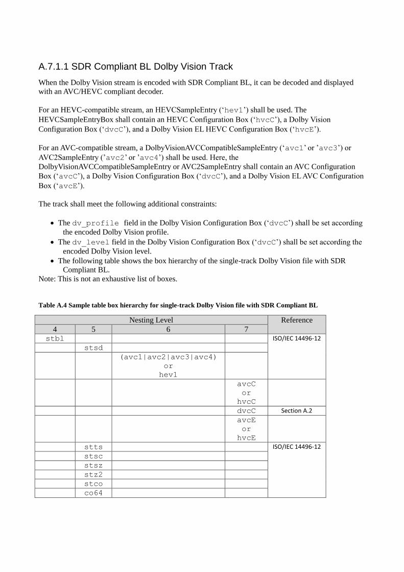
A.7.1.1 SDR Compliant BL Dolby Vision Track
When the Dolby Vision stream is encoded with SDR Compliant BL, it can be decoded and displayed
with an AVC/HEVC compliant decoder.
For an HEVC-compatible stream, an HEVCSampleEntry (‘hev1’) shall be used. The
HEVCSampleEntryBox shall contain an HEVC Configuration Box (‘hvcC’), a Dolby Vision
Configuration Box (‘dvcC’), and a Dolby Vision EL HEVC Configuration Box (‘hvcE’).
For an AVC-compatible stream, a DolbyVisionAVCCompatibleSampleEntry (‘avc1’ or ’avc3’) or
AVC2SampleEntry (’avc2’ or ’avc4’) shall be used. Here, the
DolbyVisionAVCCompatibleSampleEntry or AVC2SampleEntry shall contain an AVC Configuration
Box (‘avcC’), a Dolby Vision Configuration Box (‘dvcC’), and a Dolby Vision EL AVC Configuration
Box (‘avcE’).
The track shall meet the following additional constraints:
The dv_profile field in the Dolby Vision Configuration Box (‘dvcC’) shall be set according
the encoded Dolby Vision profile.
The dv_level field in the Dolby Vision Configuration Box (‘dvcC’) shall be set according the
encoded Dolby Vision level.
The following table shows the box hierarchy of the single-track Dolby Vision file with SDR
Compliant BL.
Note: This is not an exhaustive list of boxes.
Table A.4 Sample table box hierarchy for single-track Dolby Vision file with SDR Compliant BL
Nesting Level Reference
4 5 6 7 stbl ISO/IEC 14496-12
stsd
(avc1|avc2|avc3|avc4)
or
hev1
avcC
or
hvcC
dvcC Section A.2
avcE
or
hvcE
stts ISO/IEC 14496-12
stsc
stsz
stz2
stco
co64
Page 16
Note: It is important to carefully select the sample entry to be compliant with the desired base layer
requirements.
A.7.1.2 Non-SDR Compliant BL Dolby Vision Track
When the Dolby Vision stream is encoded with Non-SDR Compliant BL, the BL is not compliant with
SDR. In this case, a
DolbyVisionHEVCSampleEntry (‘dvhe’),
DolbyVisionHVC1SampleEntry (‘dvh1’),
DolbyVisionAVC3SampleEntry (‘dvav’) or
DolbyVisionAVC1SampleEntry (‘dva1’) shall be used.
The visual sample entries shall contain an AVC or HEVC Configuration Box
(‘avcC’ or `hvcC’), a Dolby Vision Configuration Box (‘dvcC’) and a Dolby Vision EL AVC or
HEVC Configuration Box (‘avcE’ or `hvcE’).
The track shall meet the following additional constraints:
In the handler reference box, the handler_type field shall be set to ’vide’.
The media information header box shall contain a video media header box.
The dv_profile field in the Dolby Vision Configuration Box (‘dvcC’) shall be set according
the encoded Dolby Vision profile.
The dv_level field in the Dolby Vision Configuration Box (‘dvcC’) shall be set according the
encoded Dolby Vision level.
The following table shows the box hierarchy of the single-track Dolby Vision file.
Note: This is not an exhaustive list of boxes.
Table 5 Sample table box hierarchy for single-track Dolby Vision file with Non-SDR Compliant BL
Nesting Level Reference
4 5 6 7 stbl ISO/IEC 14496-12
stsd
dvav, dva1, dvhe, or dvh1
avcC
or
hvcC
dvcC Section A.2
avcE
or
hvcE
stts ISO/IEC 14496-12
stsc
stsz
stz2
stco
co64
Page 17
A.7.2 Dual-track file
As a dual-track file, Dolby Vision BL and EL (or, optionally, EL+RPU) substreams are packaged in
separate video tracks. Each track has different sample descriptions.
A.7.2.1 BL Track
The BL track is SDR compliant and can be decoded and displayed with a compliant AVC/HEVC
decoder.
Note: If the sample entry is not set to ‘avc3’ or ‘hev1’ it will not be compliant with DECE CFF v2.0.
A.7.2.2 EL Track
The EL track is not SDR compliant. In this case, a
DolbyVisionHEVCVisualSampleEntry (‘dvhe’),
DolbyVisionHVC1VisualSampleEntry (‘dvh1’),
DolbyVisionAVC3VisualSampleEntry (‘dvav’) or
DolbyVisionAVC1VisualSampleEntry (‘dva1’) shall be used.
The visual sample entries shall contain an AVC or HEVC Configuration Box (‘avcC’ or `hvcC’), and a
Dolby Vision Configuration Box (‘dvcC’).
Notice that the Dolby Vision EL AVC or HEVC Configuration Box
(‘avcE’ or ‘hvcE’) shall not be present.
The track shall meet the following constraints:
In the handler reference box, the handler_type field shall be set to ’vide’.
The media information header box shall contain a video media header box.
The dependency between the Dolby Vision base and enhancement track shall be signaled by the
‘tref’ box. The reference_type shall be set to ‘vdep’.
The dv_profile field in the Dolby Vision Configuration Box (‘dvcC’) shall be set according
the encoded Dolby Vision profile.
The dv_level field in the Dolby Vision Configuration Box (‘dvcC’) shall be set according the
encoded Dolby Vision level.
The rpu_present_flag shall be set to 0 or 1.
The el_present_flag shall be set to 0 or 1.
The bl_present_flag shall be set to 0.
The following table shows the box hierarchy of the EL track of a dual-Dolby Vision file.
Note: This is not an exhaustive list of boxes.
Table 6 Sample table box hierarchy for the EL track of a dual-track Dolby Vision file
Nesting Level Reference
4 5 6 7
stbl ISO/IEC 14496-12
stsd
dvav, dva1, dvhe, or dvh1 Section A.3
avcC
or
hvcC
Page 18
dvcC Section 3.1
stts ISO/IEC 14496-12
stsc
stsz
stz2
stco
co64
A.7.3 Constraints on the ISO base media file format boxes
A.7.3.1 Constraints on Movie Fragments
For a dual-track file, the movie fragments carrying the BL and EL shall meet the following constraints:
The adjacent movie fragments (‘moof’ and ‘mdat’) for the base and enhancement track shall be
interleaved with BL followed by EL. BL and EL samples shall be placed in separate Movie
Fragments and that each BL Movie Fragment shall be immediately followed by an EL movie
fragment containing the same number of samples with identical composition timestamps.
The track fragment run box (‘trun’) for the base and enhancement track shall contain the same
number of samples.
A.7.3.2 Constraints on Track Fragment Random Access Box
The track fragment random access box (‘tfra’) for the base and enhancement track shall conform to
the ISO/IEC 14496-12 (section 8.8.10) (see Resources) and meet the following additional constraint:
The value of the time field in the track fragment random access box indicates the presentation
time of a random accessible sample. This time value shall be identical for every corresponding
random accessible sample in the base and enhancement track.
Page 19
Annex B – Signaling Dolby Vision Profiles and Levels
This Annex defines the detailed list of Dolby Vision profile/levels and how to represent them in a string
format. This string can be used for identifying Dolby Vision device capabilities and identifying the type
of the Dolby Vision streams presented to device through various delivery mechanisms such as HTML
5.0 and MPEG-DASH.
B.1.1 Terms, Definitions, and Abbreviated Terms
B1.1.1 Abbreviated Terms
The following table describes the terminology and abbreviations used throughout this document.
BL Base layer.
EL Enhancement layer.
AVC Advanced Video Coding.
HEVC High efficient video coding.
SDR Standard Dynamic Range (rec.709 colorspace and 100 nits maximum lumiance)
Blu-ray HDR Ultra HD Blu-rayTM High Dynamic Range
HDR10 DASH-IF HDR10
GOP Group of Pictures
B.2 Dolby Vision Profiles and levels
The Dolby Vision codec provides a rich feature set to support various ecosystems such as Over the Top
streaming, Broadcast television, Blu-Ray discs, and OTT streaming. The codec also supports many
different device implementation types such as GPU accelerated software implementation, full-fledged
hardware implementation, and hardware plus software combination. One of the Dolby Vision codec
features allows choosing the type of backward compatibility such as non-backward compatible or
backward compatible with SDR. A Dolby Vision capable device may not have all the features or options
implemented, hence it is critical the device advertises the capabilities and content server provides
accurate Dolby vision stream type information.
B.2.1 Dolby Vision Profiles
Following are the currently supported Dolby Vision profiles:
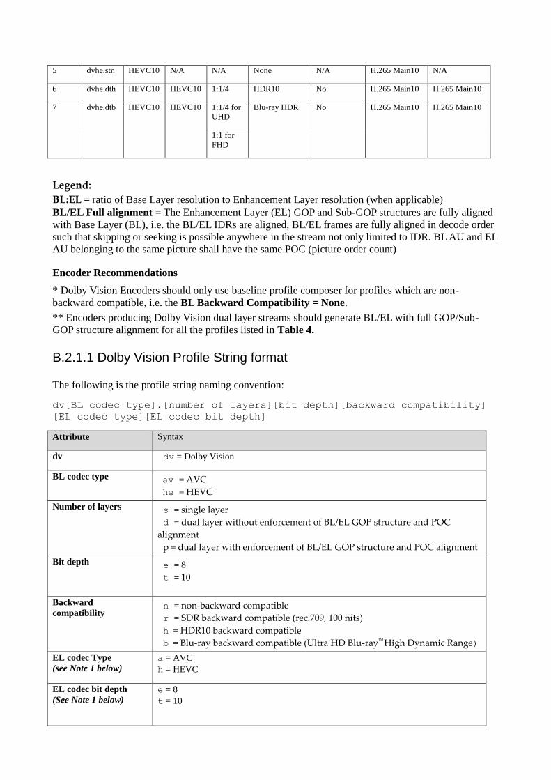
Table 7 Dolby Vision Profiles
Profile
ID
Profile
Name
BL
Codec
EL
Codec
BL:EL BL Backward
Compatibility*
BL/EL Full
Alignment**
BL Codec
Profile
EL Codec
Profile
0 dvav.per AVC AVC 1:1/4 SDR Yes H.264 High H.264 High
1 dvav.pen AVC AVC 1:1 None Yes H.264 High H.264 High
2 dvhe.der HEVC8 HEVC8 1:1/4 SDR No H.265 Main H.265 Main
3 dvhe.den HEVC8 HEVC8 1:1 None No H.265 Main H.265 Main
4 dvhe.dtr HEVC10 HEVC10 1:1/4 SDR No H.265 Main10 H.265 Main10
Page 20
5 dvhe.stn HEVC10 N/A N/A None N/A H.265 Main10 N/A
6 dvhe.dth HEVC10 HEVC10 1:1/4 HDR10 No H.265 Main10 H.265 Main10
7 dvhe.dtb HEVC10 HEVC10 1:1/4 for
UHD
Blu-ray HDR No H.265 Main10 H.265 Main10
1:1 for
FHD
Legend:
BL:EL = ratio of Base Layer resolution to Enhancement Layer resolution (when applicable)
BL/EL Full alignment = The Enhancement Layer (EL) GOP and Sub-GOP structures are fully aligned
with Base Layer (BL), i.e. the BL/EL IDRs are aligned, BL/EL frames are fully aligned in decode order
such that skipping or seeking is possible anywhere in the stream not only limited to IDR. BL AU and EL
AU belonging to the same picture shall have the same POC (picture order count)
Encoder Recommendations
* Dolby Vision Encoders should only use baseline profile composer for profiles which are non-
backward compatible, i.e. the BL Backward Compatibility = None.
** Encoders producing Dolby Vision dual layer streams should generate BL/EL with full GOP/Sub-
GOP structure alignment for all the profiles listed in Table 4.
B.2.1.1 Dolby Vision Profile String format
The following is the profile string naming convention:
dv[BL codec type].[number of layers][bit depth][backward compatibility]
[EL codec type][EL codec bit depth]
Attribute Syntax
dv dv = Dolby Vision
BL codec type av = AVC
he = HEVC
Number of layers s = single layer
d = dual layer without enforcement of BL/EL GOP structure and POC
alignment
p = dual layer with enforcement of BL/EL GOP structure and POC alignment
Bit depth e = 8
t = 10
Backward
compatibility n = non-backward compatible
r = SDR backward compatible (rec.709, 100 nits)
h = HDR10 backward compatible
b = Blu-ray backward compatible (Ultra HD Blu-rayTM
High Dynamic Range)
EL codec Type
(see Note 1 below)
a = AVC
h = HEVC
EL codec bit depth
(See Note 1 below)
e = 8
t = 10
Page 21
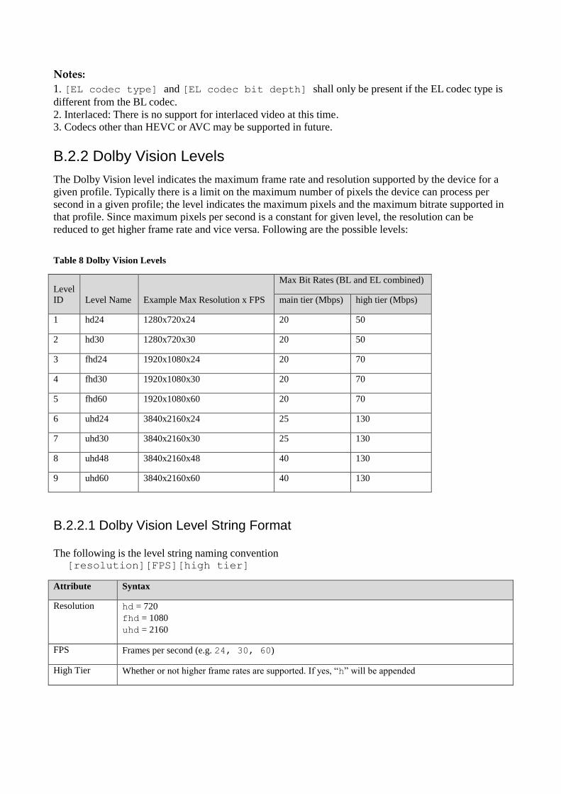
Notes:
1. [EL codec type] and [EL codec bit depth] shall only be present if the EL codec type is
different from the BL codec.
2. Interlaced: There is no support for interlaced video at this time.
3. Codecs other than HEVC or AVC may be supported in future.
B.2.2 Dolby Vision Levels
The Dolby Vision level indicates the maximum frame rate and resolution supported by the device for a
given profile. Typically there is a limit on the maximum number of pixels the device can process per
second in a given profile; the level indicates the maximum pixels and the maximum bitrate supported in
that profile. Since maximum pixels per second is a constant for given level, the resolution can be
reduced to get higher frame rate and vice versa. Following are the possible levels:
Table 8 Dolby Vision Levels
Level
ID Level Name Example Max Resolution x FPS
Max Bit Rates (BL and EL combined)
main tier (Mbps) high tier (Mbps)
1 hd24 1280x720x24 20 50
2 hd30 1280x720x30 20 50
3 fhd24 1920x1080x24 20 70
4 fhd30 1920x1080x30 20 70
5 fhd60 1920x1080x60 20 70
6 uhd24 3840x2160x24 25 130
7 uhd30 3840x2160x30 25 130
8 uhd48 3840x2160x48 40 130
9 uhd60 3840x2160x60 40 130
B.2.2.1 Dolby Vision Level String Format
The following is the level string naming convention [resolution][FPS][high tier]
Attribute Syntax
Resolution hd = 720
fhd = 1080
uhd = 2160
FPS Frames per second (e.g. 24, 30, 60)
High Tier Whether or not higher frame rates are supported. If yes, “h” will be appended
Page 22
B.2.3 Dolby Vision Codec Profile and Level String
The profile and level string is recommended to be joined in the following manner:
Format:
[Profile String].[Level String]
Examples
• dvav.per.fhd30
(dual layer avc 8 bit with enforcement of BL/EL GOP Structure and POC alignment, rec709
backwards compatible, 1920x1080@30fps)
• dvhe.stn.uhd30
(single layer hevc 10 bit non-backwards compatible, 3840x2160@30fps)
B.2.3.1 Device Capabilities
The device capabilities can be expressed in many ways depending on the protocol used by the streaming
service or VOD service. The device could maintain a list of supported capabilities in an array:
String capabilities [] = {“dvhe.dtr.uhd24”, “dvhe.stn.uhd30”}
After receiving the manifest the Player could iterate over the stream types and check whether a stream
type is supported by searching the capabilities[].
User Agent String
When using HTTP, the device could send the capabilities via the user agent string in HTTP request in
following manner:
Opera/9.80 (Linux armv71) Presto/2.12.407 Version/12.51 Model-
UHD+dvhe.dtr.uhd24+dvhe.stn.uhd30/1.0.0 (Manufacturer name, Model)
A server program can search for “+dv” to determine whether Dolby Vision is supported and further
identify the profiles and level supported by parsing the characters following the +dv. Multiple
profiles/level pairs can be listed with ‘+’ beginning each profile/level pair.
Page 23
Annex C – Display Management Message
C.1.1 Introduction
A display management (DM) message contains metadata in order to provide dynamic information about
the colour volume of the video signal. This metadata can be employed by the display to adapt the
delivered HDR imagery to the capability of the display device. The information conveyed in this
message is intended to be adequate for purposes corresponding to the use of Society of Motion Picture
and Television Engineers ST 2094-1 and ST 2094-10.
The syntax and semantics for DM_data() are defined in clause C.2.
C.2 Syntax and Semantics
Table C.1: DM_data()
DM_data () { Descriptor
app_identifier ue(v)
app_version ue(v)
metadata_refresh_flag u(1)
if( metadata_refresh_flag ) {
num_ext_blocks ue(v)
if( num_ext_blocks ) {
while( !byte_aligned() )
dm_alignment_zero_bit f(1)
for( i = 0; i < num_ext_blocks; i ++ ) {
ext_dm_data_block(i)
}
}
else {
while( !byte_aligned() )
dm_alignment_zero_bit f(1)
}
}
}
Table C.2: ext_dm_data_block()
ext_dm_data_block() { Descriptor
ext_block_length ue(v)
ext_block_level u(8)
ext_dm_data_block_payload( ext_block_length, ext_block_level )
}
Table C.3: ext_dm_data_block_payload()
ext_dm_data_block_payload( ext_block_length, ext_block_level ) { Descriptor
ext_block_len_bits = 8 * ext_block_length
ext_block_use_bits = 0
if( ext_block_level == 1 ) {
Page 24
min_PQ u(12)
max_PQ u(12)
avg_PQ u(12)
ext_block_use_bits += 36
}
if( ext_block_level == 2 ) {
target_max_PQ u(12)
trim_slope u(12)
trim_offset u(12)
trim_power u(12)
trim_chroma_weight u(12)
trim_saturation_gain u(12)
ms_weight i(13)
ext_block_use_bits += 85
}
if( ext_block_level == 5 ) {
active_area_left_offset u(13)
active_area_right_offset u(13)
active_area_top_offset u(13)
active_area_bottom_offset u(13)
ext_block_use_bits += 52
}
while( ext_block_use_bits++ < ext_block_len_bits )
ext_dm_alignment_zero_bit f(1)
}
This clause defines the semantics for DM_data().
For the purposes of the present clause, the following mathematical functions apply:
Abs(x) =
Floor( x ) is the largest integer less than or equal to x.
Sign(x) =
Clip3(x, y, z) =
Round(x) = Sign(x)*Floor(Abs(x)+0.5)
/ = Integer division with truncation of the result toward zero. For example, 7/4 and −7/−4 are truncated to 1 and −7/4
and 7/−4 are truncated to −1.
app_identifier identifies an application in the ST 2094 suite.
app_version specifies the application version in the application in the ST 2094 suite.
metadata_refresh_flag when set equal to 1 cancels the persistence of any previous extended display mapping metadata
in output order and indicates that extended display mapping metadata follows. The extended display mapping metadata
Page 25
persists from the coded picture to which the SEI message containing DM_data() is associated (inclusive) to the coded
picture to which the next SEI message containing DM_data() and with metadata_refresh_flag set equal to 1 in output
order is associated (exclusive) or (otherwise) to the last picture in the coded video seqeunce (inclusive). When set equal
to 0 this flag indicates that the extended display mapping metadata does not follow.
num_ext_blocks specifies the number of extended display mapping metadata blocks. The value shall be in the range of
1 to 254, inclusive.
dm_alignment_zero_bit shall be equal to 0.
ext_block_length[ i ] is used to derive the size of the i-th extended display mapping metadata block payload in bytes.
The value shall be in the range of 0 to 1023, inclusive.
ext_block_level[ i ] specifies the level of payload contained in the i-th extended display mapping metadata block. The
value shall be in the range of 0 to 255, inclusive. The corresponding extended display mapping metadata block types are
defined in Table E.1.4. Values of ext_block_level[ i ] that are ATSC reserved shall not be present in the bitstreams
conforming to this version of ATSC specification. Blocks using ATSC reserved values shall be ignored.
When the value of ext_block_level[ i ] is set equal to 1, the value of ext_block_length[ i ] shall be set equal to 5.
When the value of ext_block_level[ i ] is set equal to 2, the value of ext_block_length[ i ] shall be set equal to 11.
When the value of ext_block_level[ i ] is set equal to 5, the value of ext_block_length[ i ] shall be set equal to 7.
Table C.8: Definition of extended display mapping metadata block type
ext_block_level extended metadata block type
0 Reserved
1 Level 1 Metadata – Content Range
2 Level 2 Metadata – Trim Pass
3 Reserved
4 Reserved
5 Level 5 Metadata – Active Area
6…255 Reserved
When an extended display mapping metadata block with ext_block_level equal to 5 is present, the following constraints
shall apply:
An extended display mapping metadata block with ext_block_level equal to 5 shall be preceded by at least one
extended display mapping metadata block with ext_block_level equal to 1 or 2.
Between any two extended display mapping metadata blocks with ext_block_level equal to 5, there shall be at
least one extended display mapping metadata block with ext_block_level equal to 1 or 2.
No extended display mapping metadata block with ext_block_level equal to 1 or 2 shall be present after the last
extended display mapping metadata block with ext_block_level equal to 5
The metadata of an extended display mapping metadata block with ext_block_level equal to 1 or 2 shall be
applied to the active area specified by the first extended display mapping metadata block with ext_block_level
equal to 5 following this block.
When the active area defined by the current extended display mapping metadata block with ext_block_level equal to 5
overlaps with the active area defined by preceding extended display mapping metadata blocks with ext_block_level
equal to 5, all metadata of the extended display mapping metadata blocks with ext_block_level equal to 1 or 2
associated with the current extended display mapping metadata block with ext_block_level equal to 5 shall be applied to
the pixel values of the overlapping area.
min_PQ specifies the minimum luminance value of the current picture in 12-bit PQ encoding. The value shall be in the
range of 0 to 4095, inclusive. Note that the 12-bit min_PQ value with full range is calculated as follows:
min_PQ = Clip3(0, 4095, Round(Min * 4095))
where Min is MinimumPqencodedMaxrgb as defined in clause 6.1.3 of SMPTE ST 2094-10.
max_PQ specifies the maximum luminance value of current picture in 12-bit PQ encoding. The value shall be in the
range of 0 to 4095, inclusive. Note that the 12-bit max_PQ value with full range is calculated as follows:
Page 26
max_PQ = Clip3(0, 4095, Round(Max * 4095))
where Max is MaximumPqencodedMaxrgb as defined in clause 6.1.5 of SMPTE ST 2094-10.
avg_PQ specifies the midpoint luminance value of current picture in 12-bit PQ encoding. The value shall be in the
range of 0 to 4095, inclusive. Note that the 12-bit avg_PQ value with full range is calculated as follows:
avg_PQ = Clip3(0, 4095, Round(Avg * 4095))
where Avg is AveragePqencodedMaxrgb as defined in section 6.1.4 of SMPTE ST 2094-10.
target_max_PQ specifies the maximum luminance value of a target display in 12-bit PQ encoding. The value shall be
in the range of 0 to 4095, inclusive. The target_max_PQ is the PQ encoded value of
TargetedSystemDisplayMaximumLuminance as defined in clause 10.4 of SMPTE ST 2094-1.
If there is more than one extended display mapping metadata block with ext_block_level equal to 2, those blocks shall
have no duplicated target_max_PQ.
trim_slope specifies the slope metadata. The value shall be in the range of 0 to 4095, inclusive. If trim_slope is not
present, it shall be inferred to be 2048. Note that the 12-bit slope value is calculated as follows:
𝑡𝑟𝑖𝑚_𝑠𝑙𝑜𝑝𝑒 = Clip3(0, 4095, Round((𝑆-0.5) * 4096))
where S is the ToneMappingGain as defined in clause 6.2.3 of SMPTE ST 2094-10.
trim_offset specifies the offset metadata. The value shall be in the range of 0 to 4095, inclusive. If trim_offset is not
present, it shall be inferred to be 2048. Note that the 12-bit offset value is calculated as follows:
𝑡𝑟𝑖𝑚_𝑜𝑓𝑓𝑠𝑒𝑡 = Clip3(0, 4095, Round((𝑂+0.5) * 4096))
where O is the ToneMappingOffset as defined in clause 6.2.2 of SMPTE ST 2094-10.
trim_power specifies the power metadata. The value shall be in the range of 0 to 4095, inclusive. If trim_power is not
present, it shall be inferred to be 2048. Note that the 12-bit power value is calculated as follows:
𝑡𝑟𝑖𝑚_𝑝𝑜𝑤𝑒𝑟 = Clip3(0, 4095, Round((𝑃-0.5) * 4096))
where P is the ToneMappingGamma as defined in clause 6.2.4 of SMPTE ST 2094-10.
trim_chroma_weight specifies the chroma weight metadata. The value shall be in the range of 0 to 4095, inclusive. If
trim_chroma_weight is not present, it shall be inferred to be 2048. Note that the 12-bit chroma weight value is
calculated as follows:
𝑡𝑟𝑖𝑚_𝑐ℎ𝑟𝑜ma_𝑤𝑒𝑖𝑔ℎ𝑡 = Clip3(0, 4095, Round((𝐶𝑊+0.5) * 4096))
where CW is the ChromaCompensationWeight as defined in clause 6.3.1 of SMPTE ST 2094-10.
trim_saturation_gain specifies the saturation gain metadata. The value shall be in the range of 0 to 4095, inclusive. If
trim_saturation_gain is not present, it shall be inferred to be 2048. Note that the 12-bit saturation gain value is
calculated as follows:
𝑡𝑟𝑖𝑚_𝑠𝑎𝑡𝑢𝑟𝑎𝑡𝑖𝑜𝑛_𝑔𝑎𝑖𝑛 = Clip3(0, 4095, Round((𝑆𝐺+0.5) * 4096))
where SG is the SaturationGain as defined in clause 6.3.2 of SMPTE ST 2094-10.
ms_weight specifies the multiscale weight metadata. The value shall be in the range of -1 to 4095, inclusive. If
ms_weight is not present, it shall be inferred to be 2048. Where ms_weight is equal to -1, the bit stream indicates
ms_weight is unspecified. The 13-bit multiscale weight value is calculated as follows:
𝑚𝑠_𝑤𝑒𝑖𝑔ℎ𝑡 = -1 OR Clip3(0, 4095, Round(𝑀S * 4096))
where MS is the ToneDetailFactor as defined in clause 6.4.2 of SMPTE ST 2094-10.
active_area_left_offset, active_area_right_offset, active_area_top_offset, active_area_bottom_offset specify the
active area of current picture, in terms of a rectangular region specified in picture coordinates for active area. The
values shall be in the range of 0 to 8191, inclusive. See also UpperLeftCorner and LowerRightCorner definitions in ST
2094-1.
Page 27
If active_area_left_offset, active_area_right_offset, active_area_top_offset, active_area_bottom_offset are not present,
they shall be inferred to be 0.
The coordinates of top left active pixel is derived as follows:
Xtop_left = active_area_left_offset
Ytop_left = active_area_top_offset
The coordinates of top left active pixel are defined as the UpperLeftCorner in clause 9.2 of SMPTE ST.2094-1.
With Xsize is the horizontal resolution of the current picture and Ysize is the vertical resolution of current picture, the
coordinates of bottom right active pixel are derived as follows:
Xbottom_right = XSize - 1 - active_area_right_offset
Ybottom_right = YSize - 1 - active_area_bottom_offset
where Xbottom_right greater than Xtop_left and Ybottom_right greater than Ytop_left.
The coordinates of bottom right active pixel are defined as the LowerRightCorner in clause 9.3 of SMPTE ST.2094-1.
ext_dm_alignment_zero_bit shall be equal to 0.
Annex D – Composing Metadata Message
D.1.1 Introduction
A composing metadata (CM) message contains the metadata which is needed to apply the post-processing process as
described in the ETSI [ETCCM] specification to recreate the HDR UHDTV pictures.
D.2 Syntax and Semantics
The syntax for CM_data() is shown in table D.1:
TableD.1: CM_data()
CM_data() { Descriptor
ccm_profile u(4)
ccm_level u(4)
coefficient_log2_denom ue(v)
BL_bit_depth_minus8 ue(v)
EL_bit_depth_minus8 ue(v)
hdr_bit_depth_minus8 ue(v)
disable_residual_flag u(1)
for( cmp = 0; cmp < 3; cmp++ ) {
num_pivots_minus2[ cmp ] ue(v)
for ( pivot_idx = 0; pivot_idx < num_pivots_minus2[ cmp ] + 2; pivot_idx + + ) {
pred_pivot_value[ cmp ][ pivot_idx ] u(v)
} // end of pivot points for BL three components
} //cmp
for ( cmp = 0; cmp < 3; cmp++ ) { //mapping parameters
for ( pivot_idx = 0; pivot_idx < num_pivots_minus2[ cmp ] + 1; pivot_idx++ ) {
Page 28
mapping_idc[ cmp ][ pivot_idx ] ue(v)
if( mapping_idc [ cmp ][ pivot_idx ] == MAPPING_POLYNOMIAL ) {
poly_order_minus1[ cmp ][ pivot_idx ] ue(v)
for( i = 0 ; i <= poly_order_minus1[ cmp ][ pivot_idx ] + 1; i ++ ) {
poly_coef_int[ cmp ][ pivot_idx ][ i ] se(v)
poly_coef[ cmp ][ pivot_idx ][ i ] u(v)
}
else if( mapping_idc [ cmp ][ pivot_idx ] == MAPPING_MMR ) {
mmr_order_minus1[ cmp ][ pivot_idx ] u(2)
mmr_constant_int[ cmp ][ pivot_idx ] se(v)
mmr_constant[ cmp ][ pivot_idx ] u(v)
for( i = 1; i <= mmr_order_minus1 + 1; i ++ ) {
for (j = 0; j < 7; j++) {
mmr_coef_int[ cmp ][ pivot_idx ][ i ] [ j ] se(v)
mmr_coef[ cmp ][ pivot_idx ][ i ][ j ] u(v)
} // the j-th coefficients
} // the i-th order
} // MMR coefficients
} // pivot_idx
} // cmp
if ( !disable_residual_flag ) {
for ( cmp = 0; cmp < 3; cmp++ ) { //quantization parameters
nlq_offset[ cmp ] u(v)
hdr_in_max_int[ cmp ] ue(v)
hdr_in_max[ cmp ] u(v)
linear_deadzone_slope_int[ cmp ] ue(v)
linear_deadzone_slope[ cmp ] u(v)
linear_deadzone_threshold_int[ cmp ] ue(v)
linear_deadzone_threshold[ cmp ] u(v)
} // cmp
} // disable_residue_flag
while( !byte_aligned() )
cm_alignment_zero_bit f(1)
}
The definitions of the header parameter values are contained in [ETCCM], Section 5.3.2, “CM Header Parameter
Definitions”
The definitions of the mapping parameter values are contained in [ETCCM], Section 5.3.3, “CM Mapping Parameter
Definitions”
Parameter cm_alignment_zero_bit shall be equal to 0.
Annex E – Sample Dual-layer MPD Below is an example dual-layer MPD, with dual adaptation sets – both a Base layer and an
Enhancement Layer. Items of note are highlighted:
Page 29
<Period>
<!-- Video -->
<AdaptationSet subsegmentAlignment="true" subsegmentStartsWithSAP="1"
frameRate="24000/1001">
<Representation mimeType="video/mp4" codecs=" hvc1.2.100000000.L150.B0" id="base-
layer"
bandwidth="14156144" width="3840" height="2160">
<BaseURL>BL_dual_track_BC.mp4</BaseURL>
<SegmentBase indexRange="795-1210">
<Initialization range="0-794"/>
</SegmentBase>
</Representation>
<Representation mimeType="video/mp4" codecs="dvhe.dtr" id="enhancement-layer"
dependencyId="base-layer" bandwidth="3466528" width="1920" height="1080">
<BaseURL>EL_dual_track_BC.mp4</BaseURL>
<SegmentBase indexRange="704-1119">
<Initialization range="0-703"/>
</SegmentBase>
</Representation>
</AdaptationSet>
<!-- Audio -->
<AdaptationSet mimeType="audio/mp4" codecs="ec-3" lang="und"
subsegmentAlignment="true" subsegmentStartsWithSAP="1">
<Representation id="2" bandwidth="192000">
<AudioChannelConfiguration
schemeIdUri="tag:dolby.com,2014:dash:audio_channel_configuration:2011"
value="F801"/>
<BaseURL>audio.mp4</BaseURL>
<SegmentBase indexRange="652-875">
<Initialization range="0-651"/>
</SegmentBase>
</Representation>
</AdaptationSet>
</Period>
</MPD>