Abstract• This presentation provides updates from the latest 3GPP RAN1 meeting
(RAN1#92 BIS, 16-20/April in Sanya, China) on the standardization of NR-Unlicensed with a focus on fair coexistence with 802.11.
Slide 2
May 2018
Submission
doc.: IEEE 802.11-18/0916r0
OutlineThe presentation discusses the following topics on NR-Unlicensed (NRU):
1. LBT features to considered for NR-U2. Simulation configuration for Indoor sub-7GHz 3. Simulation configuration for Outdoor sub-7GHz4. Next Steps
Slide 3
May 2018
Submission
doc.: IEEE 802.11-18/0916r0NR-Unlicensed: Features to be considered (1)
Slide 4
May 2018
The following agreements in NR-U are relevant for 802.11 and for fair coexistence between 802.11 and NR-U. They are copied below from [1]:
1. Study possible enhancements for HARQ operation 2. Baseline for study: If absence of Wi-Fi cannot be guaranteed (e.g. by regulation) in the band (sub-7 GHz) where NR-U is operating, the
NR-U operating bandwidth is an integer multiple of 20MHz 3. At least for band where absence of Wi-Fi cannot be guaranteed (e.g. by regulation), LBT can be performed in units of 20 MHz.
• FFS: details on how to perform LBT for as single carrier with bandwidth greater than 20 MHz, i.e., integer multiples of 20 MHz.4. Study whether or not the following techniques enhance performance beyond the baseline LBT mechanisms
1. Techniques to cope with directional antennas/transmissions2. Receiver assisted LBT : RTS/CTS type mechanism
• On-demand receiver assisted LBT: For example receiver assisted LBT enabled only when needed 3. Techniques to enhance spatial reuse 4. Preamble detection5. Enhancements to baseline LBT mechanisms above 7 GHz
5. Note: LTE-LAA LBT mechanism are assumed as baseline for evaluations for 5GHz. 6. Note: Other aspects are not precluded from being included
Submission
doc.: IEEE 802.11-18/0916r0NR-Unlicensed: Features to be considered (2)
Slide 5
May 2018
Notes (on the agreements in the previous page):1. The following clauses were put in order to ensure fair coexistence with 802.11: In the presence of 802.11 a) NR-U LBT will be
performed in units of 20 MHz and b) NR-U operating bandwidth will be an integer multiple of 20 MHz.2. New channel access mechanisms can be proposed for NR-U as stated the agreements. 3. It will be helpful for fair coexistence between 802.11 and NR-U if participants in 802.11 or the 802.11 Coexistence SC provides its
views on new LBT schemes for NR-U to RAN1 along with an analysis of how they ensure higher efficiency and/or better coexistence. The proposals (either individual company proposals or an LS from 802.11) can be submitted to the next RAN1 meeting between 21-25/May.
Submission
doc.: IEEE 802.11-18/0916r0
NR-U simulation configuration for sub-7GHz (1)
Slide 6
May 2018
• The simulation configuration for sub-7 GHz will be used to study the performance of the different features proposed for NR-U as well as the coexistence between 802.11ac and NR-U.
• It is also possible that the same configuration may be used to study the coexistence between 802.11ax and NR-U. • Given this, it is very important that the simulation configuration mirrors typical deployments of Indoor and Outdoor 802.11 networks.• The RSSI CDF of the serving and interfering links of a network are an important metric to characterize and compare network topologies.
• The RSSI CDF of the serving links characterize the distribution of the active data bearing links in the network. • The RSSI CDF of the interfering links characterize the distribution of the interferers which would be the nodes that perform LBT.
• 802.11 network data collected by Cisco, Boingo Wireless and HPE show that a significant % of serving links have RSSI below -72dBm.• 802.11 network data collected by CableLabs show that if the CDF over both serving and non-serving links are considered, a majority of
such links are below -72dBm.• The data has been presented to 3GPP RAN1 in R1-1805555 [2].
Submission
doc.: IEEE 802.11-18/0916r0
NR-U simulation configuration for sub-7GHz (2)
Slide 7
May 2018
• In contrast, in the LAA simulation methodology, < 1% of all links in the Indoor configuration and < 7% of all links in the Outdoor configuration had RSSI below -72dBm.
RSSI CDF of LAA Indoor Topology RSSI CDF of LAA Outdoor Topology
• Given the above, it was very important to ensure that the NR-U simulation configuration, especially for sub 7 GHz (since this is the band were most 802.11 technologies are deployed) reflect realistic 802.11 networks.
Submission
doc.: IEEE 802.11-18/0916r0
NR-U simulation configuration for Indoor sub-7GHz (3)
Slide 8
May 2018
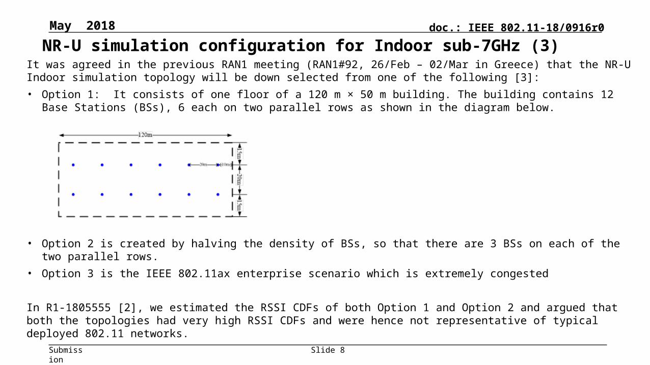
It was agreed in the previous RAN1 meeting (RAN1#92, 26/Feb – 02/Mar in Greece) that the NR-U Indoor simulation topology will be down selected from one of the following [3]: • Option 1: It consists of one floor of a 120 m × 50 m building. The building contains 12 Base Stations (BSs), 6 each on two parallel rows
as shown in the diagram below.
• Option 2 is created by halving the density of BSs, so that there are 3 BSs on each of the two parallel rows.• Option 3 is the IEEE 802.11ax enterprise scenario which is extremely congested
In R1-1805555 [2], we estimated the RSSI CDFs of both Option 1 and Option 2 and argued that both the topologies had very high RSSI CDFs and were hence not representative of typical deployed 802.11 networks.
Submission
doc.: IEEE 802.11-18/0916r0
NR-U simulation configuration for Indoor sub-7GHz (4)
Slide 9
May 2018
Hence, we proposed in [2] that the network topology be modified in the following manner:1. Change the LOS probability model from Indoor Open office to Indoor Mixed Office ([4] Table 7.4.2-1)2. Distribute users of a BS over twice the area i.e. across the full Indoor width of 50m instead of 25m as earlier.The above changes lower the RSSI CDF (shown in the next slide) to what is more representative of 802.11 networks.
Observation (copied from [2]):
The RSSI CDF for Option 1 is as follows:• Serving links: 2% of links are below -62dBm and 0% are
below -72dBm.• Interfering links: 35% of links are below -62dBm and
23% are below -72dBm.
The RSSI CDF for Option 2 is as follows:• Serving links: 4% of links are below -62dBm and 1% are
below -72dBm.• Interfering links: 38% of links are below -62dBm and
25% are below -72dBm.
Submission
doc.: IEEE 802.11-18/0916r0
NR-U simulation configuration for Indoor sub-7GHz (5)
Slide 10
May 2018
Modified Option 2 was accepted as the network topology for Indoor sub-7 GHz evaluations in 3GPP RAN1. In view of very divergent RSSI cdf observations presented by companies in the meeting, we also proposed an effort to calibrate the environment across companies. In an email discussion following the RAN1 #92bis meeting, many companies participated to calibrate their network topology and to finally agree on some of the tuning parameters. The agreed configuration is described in detail in the next slide.
Observation (copied from [2]):
The RSSI CDF for modified Option 1 is as follows:• Serving links: 20% of links are below -62dBm and 10%
are below -72dBm• Interfering links: 70% of links are below -62dBm and
50% are below -72dBm. The RSSI CDF for modified Option 2 is as follows:• Serving links: 23% of links are below -62dBm and 12%
are below -72dBm• Interfering links: 70% of links are below -62dBm and
50% are below -72dBm.
Submission
doc.: IEEE 802.11-18/0916r0
NR-U simulation configuration for Indoor sub-7GHz (6)
Slide 11
May 2018
Indoor Network Layout for sub 7-GHz evaluations:• 120m x 80m rectangle with 2 operators and 3 gNB/APs per operator. • The red dots represent gNB/APs from one operator and the blue dots represent gNB/APs from another operator.• a = 20m, b = 40m, c = 20m and d = 40m. • All gNB/APs occupy the same 20 MHz channel• There are 5 UE/clients per gNB/AP. • UE/clients for each operator are uniformly distributed over the entire 120m x 80m layout.
Pathloss model:• Indoor Hotspot pathloss specified in [5] • The LOS/NLOS probability based on the Indoor Mixed Office model specified in [4] • The pathloss ballpark matches the 802.11ax pathloss model specified in IEEE 802.11-
14/0980r5 section 1• MIMO antenna arrays are assumed at the gNB/AP and UE/client: gNB/AP: (M, N, P, Mg, Ng) = (1, 2, 2, 1, 1), dH = dV = 0.5 λ UE/Client: Baseline Tx/Rx: (M, N, P, Mg, Ng) = (1, 1, 2, 1, 1), dH = dV = 0.5 λ Optional Tx/Rx: (M, N, P, Mg, Ng) = (1, 2, 2, 1, 1), dH = dV = 0.5 λ
Submission
doc.: IEEE 802.11-18/0916r0
NR-U simulation configuration for Indoor sub-7GHz (7)
Slide 12
May 2018
The RSSI distribution of the Indoor topology is as follows (simulated RSSI CDFs provided by 10 companies):
Observation: This topology accepted for NR-U Indoor sub 7-GHz evaluations is more representative of deployed 802.11 networks than the LAA Indoor topology. Also, the RSSI cdfs for all the 10 companies are similar which increases the comparability and reliability of simulation results generated by different companies.
Submission
doc.: IEEE 802.11-18/0916r0
NR-U simulation configuration for Outdoor sub-7GHz (1)
Slide 13
May 2018
The Outdoor sub 7 GHz topology is still under discussion. RAN1 has broadly agreed to selecting one of two alternatives. Text in italicized brown are copied from RAN1 agreements. [] imply suggested values that haven’t yet been agreed.• Alt 1: Each operator randomly drop [1 or 2] micro-layer TRPs within each macro cell with minimum distance between gNBs as in NR
• Use NR dense Urban option 1 (gNB dropped at the center of the hot-spot)• Independent dropping between two operators• Use the NR current [57.9] meters intra-operator minimum distance• Use [10] meters as the inter-operator minimum distance• UE randomly dropped within [28.9] meters within the serving cell
The schematic of Alternative 1 is as shown below for the case of 3 Micro AP/gNBs per Macro AP/gNB. A TRP is a Transmission-Reception Point or a AP/gNB. The inter-operator macro gNB distance is 200m.
• Comment: The primary argument against Alternative 1 is that in unlicensed micro deployments, such as in Indoor or Outdoor hotspots, rarely are operators able to place AP/BSs at the center of the hotspot. Rather, when a hotspot develops, the operators place AP/BSs in proximity of the hotspot depending on feasibility/restriction of placing such AP/BSs in the location.
Submission
doc.: IEEE 802.11-18/0916r0
NR-U simulation configuration for Outdoor sub-7GHz (2)
Slide 14
May 2018
Alternative 2 addresses the concerns in Alternative 1• Alt 2: Drop [1 or 2 or 3] hot spots as in NR urban option 1
• Within each hot-spot, randomly drop one gNB from each operator within a circle of radius [10] meters centered at the center of the hot-spot
• The minimum inter-gNB distance is [10] meters
• Within each hot-spot, drop UE within [28.9] meters from the hot-spot center• Parameters: Use the indoor sub7 table as baseline, with further fine tunes possibleThe schematic of Alternative 2 is as shown below.
Macro Node
Distance between cluster and macro node
Cluster 1
macro-cluster
R2
R1: radius of small cell dropping within a cluster; R2: radius of UE dropping within a cluster
Comment: In this configuration, the AP/BSs are not at the center of the hotspot. Rather, they are randomly placed in a circle inside the hotspot. The UEs are also randomly placed in a circle of larger radius and concentric with the circle that contains the AP/BSs.
Submission
doc.: IEEE 802.11-18/0916r0
Next Steps• Presently, among organizations with primary interests in 802.11, only Broadcom is participating on the
standardization of NR-U in 3GPP RAN1.• Discussions in RAN1 need to be supported by detailed simulations and analysis. It will be very difficult if there is
only one such participating organization that is providing a) simulation results for coexistence between 802.11 and NR-U; b) design proposals for NR-U channel access; c) reviewing simulation results and design proposals from all other participants in RAN1; d)attending the meetings physically and contributing to the dynamic decisions being made. It also increases the risk of adverse decisions being made, there being no redundancy in thinking and participation.
• The scope of NR-U is much broader than LAA since NR-U includes many more deployment scenarios (sub 7 GHz, mmWave, Carrier Aggregation/Dual Connectivity/Standalone). Hence, the expected standardization load is higher.
• The chances of failure i.e. of not being able to ensure fair coexistence between 802.11 and NR-U are high if Broadcom continues to be the only participant in NR-U standardization.
• It will be helpful if other participants in 802.11 or the 802.11 Coexistence SC provide its views on new channel access schemes for NR-U to RAN1 along with an analysis of how they ensure higher efficiency and/or better coexistence. The proposals (either individual company proposals or an LS from 802.11) can be submitted to the next RAN1 meeting between 21-25/May.
Slide 15
March 2018
Submission
doc.: IEEE 802.11-18/0916r0
References[1] Chairman’s notes RAN1 92-BIS final, RAN1#92 BIS, 16-20/April in Sanya, China[2] R1-1805555, Discussion on network topology for sub-7GHz coexistence evaluations between NR-U and Wi-Fi,
Broadcom, CableLabs, Charter, Cisco, Comcast, Hewlett Packard Enterprise.[3] RAN1 Chairman’s Notes, 3GPP TSG RAN WG1 Meeting #92, Athens, Greece, February 26th – March 2nd, 2018[4] “Study on channel model for frequencies from 0.5 to 100 GHz”, 3GPP TR 38.901 V14.3.0 (2017-12)[5] “Guidelines for evaluation of radio interface technologies for IMT-2020”, October 2017


![HEPTA7291 2019-02...HEPTA7291 2019-02 NR V2X Summary Report (RAN1-AH_1901) [NR Sidelink V2X] Author: Dr. Carolyn Taylor (Hepta7291) Keywords 3GPP, 5G, NR, NR V2X, NR Sidelink, Sidelink](https://static.documents.pub/doc/80x56/5f6ccafb939b7872f73d2ee5/hepta7291-2019-02-hepta7291-2019-02-nr-v2x-summary-report-ran1-ah1901-nr.jpg)


