3GPP TS 36.212 V8.3.0 (2008-05) Technical Specification 3 rd Generation Partnership Project; Technical Specification Group Radio Access Network; Evolved Universal Terrestrial Radio Access (E-UTRA); Multiplexing and channel coding (Release 8) The present document has been developed within the 3 rd Generation Partnership Project (3GPP TM ) and may be further elaborated for the purposes of 3GPP. The present document has not been subject to any approval process by the 3GPP Organizational Partners and shall not be implemented. This Specification is provided for future development work within 3GPP only. The Organizational Partners accept no liability for any use of this Specification. Specifications and reports for implementation of the 3GPP TM system should be obtained via the 3GPP Organizational Partners’ Publications Offices.
3rd Generation Partnership Project;Technical Specification Group Radio Access Network;Evolved Universal Terrestrial Radio Access (E-UTRA);
Multiplexing and channel coding(Release 8)
The present document has been developed within the 3rd Generation Partnership Project (3GPP TM) and may be further elaborated for the purposes of 3GPP. The present document has not been subject to any approval process by the 3GPP Organizational Partners and shall not be implemented. This Specification is provided for future development work within 3GPP only. The Organizational Partners accept no liability for any use of this Specification.Specifications and reports for implementation of the 3GPP TM system should be obtained via the 3GPP Organizational Partners’ Publications Offices.
3GPP
3GPP TS 36.212 V8.3.0 (2008-05)2Release 8
Keywords <keyword[, keyword]>
3GPP
Postal address
3GPP support office address 650 Route des Lucioles – Sophia Antipolis
Contents Foreword ............................................................................................................................................................5 1 Scope ........................................................................................................................................................6 2 References ................................................................................................................................................6 3 Definitions, symbols and abbreviations ...................................................................................................6 3.1 Definitions ......................................................................................................................................................... 6 3.2 Symbols ............................................................................................................................................................. 6 3.3 Abbreviations..................................................................................................................................................... 7 4 Mapping to physical channels ..................................................................................................................7 4.1 Uplink ................................................................................................................................................................ 7 4.2 Downlink ........................................................................................................................................................... 7 5 Channel coding, multiplexing and interleaving .......................................................................................8 5.1 Generic procedures ............................................................................................................................................ 8 5.1.1 CRC calculation ........................................................................................................................................... 8 5.1.2 Code block segmentation and code block CRC attachment......................................................................... 9 5.1.3 Channel coding........................................................................................................................................... 10 5.1.3.1 Tail biting convolutional coding........................................................................................................... 11 5.1.3.2 Turbo coding ........................................................................................................................................ 12 5.1.3.2.1 Turbo encoder ................................................................................................................................. 12 5.1.3.2.2 Trellis termination for turbo encoder .............................................................................................. 13 5.1.3.2.3 Turbo code internal interleaver ....................................................................................................... 13 5.1.4 Rate matching............................................................................................................................................. 15 5.1.4.1 Rate matching for turbo coded transport channels ............................................................................... 15 5.1.4.1.1 Sub-block interleaver ...................................................................................................................... 15 5.1.4.1.2 Bit collection, selection and transmission....................................................................................... 16 5.1.4.2 Rate matching for convolutionally coded transport channels and control information ........................ 18 5.1.4.2.1 Sub-block interleaver ...................................................................................................................... 18 5.1.4.2.2 Bit collection, selection and transmission....................................................................................... 19 5.1.5 Code block concatenation .......................................................................................................................... 20 5.2 Uplink transport channels and control information ......................................................................................... 20 5.2.1 Random access channel.............................................................................................................................. 20 5.2.2 Uplink shared channel................................................................................................................................ 20 5.2.2.1 Transport block CRC attachment ......................................................................................................... 21 5.2.2.2 Code block segmentation and code block CRC attachment ................................................................. 22 5.2.2.3 Channel coding of UL-SCH ................................................................................................................. 22 5.2.2.4 Rate matching....................................................................................................................................... 22 5.2.2.5 Code block concatenation..................................................................................................................... 22 5.2.2.6 Channel coding of control information................................................................................................. 22 5.2.2.6.1 Channel quality information formats for wideband CQI reports .................................................... 25 5.2.2.6.2 Channel quality information formats for higher layer configured subband CQI reports ................ 25 5.2.2.6.3 Channel quality information formats for UE selected subband CQI reports .................................. 26 5.2.2.6.4 Channel coding for CQI/PMI information in PUSCH .................................................................... 27 5.2.2.7 Data and control multiplexing .............................................................................................................. 28 5.2.2.8 Channel interleaver............................................................................................................................... 28 5.2.3 Uplink control information on PUCCH ..................................................................................................... 30 5.2.3.1 Channel coding for UCI HARQ-ACK.................................................................................................. 30 5.2.3.2 Channel coding for UCI scheduling request......................................................................................... 30 5.2.3.3 Channel coding for UCI channel quality information .......................................................................... 30 5.2.3.3.1 Channel quality information formats for wideband reports ............................................................ 31 5.2.3.3.2 Channel quality information formats for UE-selected sub-band reports......................................... 32 5.2.3.4 Channel coding for UCI channel quality information and HARQ-ACK.............................................. 33 5.2.4 Uplink control information on PUSCH without UL-SCH data.................................................................. 33 5.2.4.1 Channel coding of control information................................................................................................. 34 5.2.4.2 Control information mapping ............................................................................................................... 34 5.2.4.3 Channel interleaver............................................................................................................................... 34
3GPP
3GPP TS 36.212 V8.3.0 (2008-05)4Release 8
5.3 Downlink transport channels and control information..................................................................................... 34 5.3.1 Broadcast channel ...................................................................................................................................... 34 5.3.1.1 Transport block CRC attachment ......................................................................................................... 35 5.3.1.2 Channel coding..................................................................................................................................... 35 5.3.1.3 Rate matching....................................................................................................................................... 36 5.3.2 Downlink shared channel, Paging channel and Multicast channel............................................................. 36 5.3.2.1 Transport block CRC attachment ......................................................................................................... 37 5.3.2.2 Code block segmentation and code block CRC attachment ................................................................. 37 5.3.2.3 Channel coding..................................................................................................................................... 37 5.3.2.4 Rate matching....................................................................................................................................... 37 5.3.2.5 Code block concatenation..................................................................................................................... 37 5.3.3 Downlink control information.................................................................................................................... 37 5.3.3.1 DCI formats .......................................................................................................................................... 38 5.3.3.1.1 Format 0.......................................................................................................................................... 38 5.3.3.1.2 Format 1.......................................................................................................................................... 39 5.3.3.1.3 Format 1A....................................................................................................................................... 39 5.3.3.1.4 Format 1C ....................................................................................................................................... 40 5.3.3.1.5 Format 2.......................................................................................................................................... 40 5.3.3.1.6 Format 3.......................................................................................................................................... 44 5.3.3.1.7 Format 3A....................................................................................................................................... 44 5.3.3.2 CRC attachment.................................................................................................................................... 44 5.3.3.3 Channel coding..................................................................................................................................... 45 5.3.3.4 Rate matching....................................................................................................................................... 45 5.3.4 Control format indicator............................................................................................................................. 45 5.3.4.1 Channel coding..................................................................................................................................... 46 5.3.5 HARQ indicator ......................................................................................................................................... 46 5.3.5.1 Channel coding..................................................................................................................................... 46
Annex A (informative): Change history ...............................................................................................47
3GPP
3GPP TS 36.212 V8.3.0 (2008-05)5Release 8
Foreword This Technical Specification has been produced by the 3rd Generation Partnership Project (3GPP).
The contents of the present document are subject to continuing work within the TSG and may change following formal TSG approval. Should the TSG modify the contents of the present document, it will be re-released by the TSG with an identifying change of release date and an increase in version number as follows:
Version x.y.z
where:
x the first digit:
1 presented to TSG for information;
2 presented to TSG for approval;
3 or greater indicates TSG approved document under change control.
Y the second digit is incremented for all changes of substance, i.e. technical enhancements, corrections, updates, etc.
z the third digit is incremented when editorial only changes have been incorporated in the document.
3GPP
3GPP TS 36.212 V8.3.0 (2008-05)6Release 8
1 Scope The present document specifies the coding, multiplexing and mapping to physical channels for E-UTRA.
2 References The following documents contain provisions which, through reference in this text, constitute provisions of the present document.
• References are either specific (identified by date of publication, edition number, version number, etc.) or non-specific.
• For a specific reference, subsequent revisions do not apply.
• For a non-specific reference, the latest version applies. In the case of a reference to a 3GPP document (including a GSM document), a non-specific reference implicitly refers to the latest version of that document in the same Release as the present document.
[1] 3GPP TR 21.905: "Vocabulary for 3GPP Specifications".
[2] 3GPP TS 36.211: "Evolved Universal Terrestrial Radio Access (E-UTRA); Physical channels and modulation".
[4] 3GPP TS 36.306: "Evolved Universal Terrestrial Radio Access (E-UTRA); User Equipment (UE) radio access capabilities".
3 Definitions, symbols and abbreviations
3.1 Definitions For the purposes of the present document, the terms and definitions given in [1] and the following apply. A term defined in the present document takes precedence over the definition of the same term, if any, in [1].
Definition format
<defined term>: <definition>.
3.2 Symbols For the purposes of the present document, the following symbols apply:
DLRBN Downlink bandwidth configuration, expressed in number of resource blocks [2] ULRBN Uplink bandwidth configuration, expressed in number of resource blocks [2] PUSCHsymbN Number of SC-FDMA symbols carrying PUSCH in a subframe ULsymbN Number of SC-FDMA symbols in an uplink slot
SRSN Number of SC-FDMA symbols used for SRS transmission in a subframe (0 or 1).
3GPP
3GPP TS 36.212 V8.3.0 (2008-05)7Release 8
3.3 Abbreviations For the purposes of the present document, the following abbreviations apply:
BCH Broadcast channel CFI Control Format Indicator CP Cyclic Prefix DCI Downlink Control Information DL-SCH Downlink Shared channel FDD Frequency Division Duplexing HI HARQ indicator MCH Multicast channel PBCH Physical Broadcast channel PCFICH Physical Control Format Indicator channel PCH Paging channel PDCCH Physical Downlink Control channel PDSCH Physical Downlink Shared channel PHICH Physical HARQ indicator channel PMCH Physical Multicast channel PRACH Physical Random Access channel PUCCH Physical Uplink Control channel PUSCH Physical Uplink Shared channel RACH Random Access channel SRS Sounding Reference Signal TDD Time Division Duplexing UCI Uplink Control Information UL-SCH Uplink Shared channel
4 Mapping to physical channels
4.1 Uplink Table 4.1-1 specifies the mapping of the uplink transport channels to their corresponding physical channels. Table 4.1-2 specifies the mapping of the uplink control channel information to its corresponding physical channel.
Table 4.1-1
TrCH Physical Channel UL-SCH PUSCH RACH PRACH
Table 4.1-2
Control information Physical Channel UCI PUCCH, PUSCH
4.2 Downlink Table 4.2-1 specifies the mapping of the downlink transport channels to their corresponding physical channels. Table 4.2-2 specifies the mapping of the downlink control channel information to its corresponding physical channel.
Control information Physical Channel CFI PCFICH HI PHICH DCI PDCCH
5 Channel coding, multiplexing and interleaving Data and control streams from/to MAC layer are encoded /decoded to offer transport and control services over the radio transmission link. Channel coding scheme is a combination of error detection, error correcting, rate matching, interleaving and transport channel or control information mapping onto/splitting from physical channels.
5.1 Generic procedures This section contains coding procedures which are used for more than one transport channel or control information type.
5.1.1 CRC calculation Denote the input bits to the CRC computation by 13210 ,...,,,, −Aaaaaa , and the parity bits by 13210 ,...,,,, −Lppppp . A is the size of the input sequence and L is the number of parity bits. The parity bits are generated by one of the following cyclic generator polynomials:
- gCRC24B(D) = [D24 + D23 + D6 + D5 + D + 1] for a CRC length L = 24 and;
- gCRC16(D) = [D16 + D12 + D5 + 1] for a CRC length L = 16.
- gCRC8(D) = [D8 + D7 + D4 + D3 + D + 1] for a CRC length of L = 8.
The encoding is performed in a systematic form, which means that in GF(2), the polynomial:
231
2222
123
024
122
123
0 ...... pDpDpDpDaDaDa AAA ++++++++ −++
yields a remainder equal to 0 when divided by the corresponding length-24 CRC generator polynomial, gCRC24A(D) or gCRC24B(D), the polynomial:
151
1414
115
016
114
115
0 ...... pDpDpDpDaDaDa AAA ++++++++ −++
yields a remainder equal to 0 when divided by gCRC16(D), and the polynomial:
71
66
17
08
16
17
0 ...... pDpDpDpDaDaDa AAA ++++++++ −++
yields a remainder equal to 0 when divided by gCRC8(D).
The bits after CRC attachment are denoted by 13210 ,...,,,, −Bbbbbb , where B = A+ L. The relation between ak and bk is:
kk ab = for k = 0, 1, 2, …, A-1
3GPP
3GPP TS 36.212 V8.3.0 (2008-05)9Release 8
Akk pb −= for k = A, A+1, A+2,..., A+L-1.
5.1.2 Code block segmentation and code block CRC attachment The input bit sequence to the code block segmentation is denoted by 13210 ,...,,,, −Bbbbbb , where B > 0. If B is larger than the maximum code block size Z, segmentation of the input bit sequence is performed and an additional CRC sequence of L = 24 bits is attached to each code block. The maximum code block size is:
- Z = 6144.
If the number of filler bits F calculated below is not 0, filler bits are added to the beginning of the first block.
Note that if B < 40, filler bits are added to the beginning of the code block.
The filler bits shall be set to <NULL> at the input to the encoder.
Total number of code blocks C is determined by:
if ZB ≤
L = 0
Number of code blocks: 1=C
BB =′
else
L = 24
Number of code blocks: ( )⎡ ⎤LZBC −= / .
LCBB ⋅+=′
end if
The bits output from code block segmentation, for C ≠ 0, are denoted by ( )13210 ,...,,,, −rKrrrrr ccccc , where r is the code block number, and Kr is the number of bits for the code block number r.
Number of bits in each code block (applicable for C ≠ 0 only):
First segmentation size: +K = minimum K in table 5.1.3-3 such that BKC ′≥⋅
if 1=C
the number of code blocks with length +K is +C =1, 0=−K , 0=−C
else if 1>C
Second segmentation size: −K = maximum K in table 5.1.3-3 such that +< KK
−+ −=Δ KKK
Number of segments of size −K : ⎥⎦
⎥⎢⎣
⎢Δ
′−⋅= +
−K
BKCC .
Number of segments of size +K : −+ −= CCC .
end if
3GPP
3GPP TS 36.212 V8.3.0 (2008-05)10Release 8
Number of filler bits: BKCKCF ′−⋅+⋅= −−++
for k = 0 to F-1 -- Insertion of filler bits
>=< NULLc k0
end for
k = F
s = 0
for r = 0 to C-1
if −< Cr
−= KK r
else
+= KK r
end if
while LKk r −<
srk bc =
1+= kk
1+= ss
end while
if C >1
The sequence ( )13210 ,...,,,, −−LKrrrrr rccccc is used to calculate the CRC parity bits ( )1210 ,...,,, −Lrrrr pppp
according to subclause 5.1.1 with the generator polynomial gCRC24B(D). For CRC calculation it is assumed that filler bits, if present, have the value 0. while rKk <
)( rKLkrrk pc −+= 1+= kk
end while end if
0=k
end for
5.1.3 Channel coding The bit sequence input for a given code block to channel coding is denoted by 13210 ,...,,,, −Kccccc , where K is the
number of bits to encode. After encoding the bits are denoted by )(1
)(3
)(2
)(1
)(0 ,...,,,, i
Diiii ddddd − , where D is the number of
encoded bits per output stream and i indexes the encoder output stream. The relation between kc and )(ikd and between
K and D is dependent on the channel coding scheme.
The following channel coding schemes can be applied to TrCHs:
- tail biting convolutional coding;
- turbo coding.
3GPP
3GPP TS 36.212 V8.3.0 (2008-05)11Release 8
Usage of coding scheme and coding rate for the different types of TrCH is shown in table 5.1.3-1. Usage of coding scheme and coding rate for the different control information types is shown in table 5.1.3-2.
The values of D in connection with each coding scheme:
- tail biting convolutional coding with rate 1/3: D = K;
- turbo coding with rate 1/3: D = K + 4.
The range for the output stream index i is 0, 1 and 2 for both coding schemes.
Table 5.1.3-1: Usage of channel coding scheme and coding rate for TrCHs
TrCH Coding scheme Coding rate UL-SCH DL-SCH
PCH MCH
Turbo coding 1/3
BCH Tail biting
convolutional coding
1/3
Table 5.1.3-2: Usage of channel coding scheme and coding rate for control information
Control Information Coding scheme Coding rate
DCI Tail biting
convolutional coding
1/3
CFI Block code 1/16 HI Repetition code 1/3
Block code variable
UCI Tail biting convolutional
coding 1/3
5.1.3.1 Tail biting convolutional coding
A tail biting convolutional code with constraint length 7 and coding rate 1/3 is defined.
The configuration of the convolutional encoder is presented in figure 5.1.3-1.
The initial value of the shift register of the encoder shall be set to the values corresponding to the last 6 information bits in the input stream so that the initial and final states of the shift register are the same. Therefore, denoting the shift register of the encoder by 5210 ,...,,, ssss , then the initial value of the shift register shall be set to
kd and )2(kd correspond to the first, second and third parity streams, respectively as
shown in Figure 5.1.3-1.
5.1.3.2 Turbo coding
5.1.3.2.1 Turbo encoder
The scheme of turbo encoder is a Parallel Concatenated Convolutional Code (PCCC) with two 8-state constituent encoders and one turbo code internal interleaver. The coding rate of turbo encoder is 1/3. The structure of turbo encoder is illustrated in figure 5.1.3-2.
The transfer function of the 8-state constituent code for the PCCC is:
G(D) = ⎥⎦
⎤⎢⎣
⎡)(
)(,1
0
1
Dg
Dg,
where
g0(D) = 1 + D2 + D3, g1(D) = 1 + D + D3.
The initial value of the shift registers of the 8-state constituent encoders shall be all zeros when starting to encode the input bits.
The output from the turbo encoder is
kk xd =)0(
kk zd =)1(
kk zd ′=)2(
for 1,...,2,1,0 −= Kk .
If the code block to be encoded is the 0-th code block and the number of filler bits is greater than zero, i.e., F > 0, then the encoder shall set ck, = 0, k = 0,…,(F-1) at its input and shall set >=< NULLd k
)0( , k = 0,…,(F-1) and
>=< NULLd k)1( , k = 0,…,(F-1) at its output.
The bits input to the turbo encoder are denoted by 13210 ,...,,,, −Kccccc , and the bits output from the first and second 8-state constituent encoders are denoted by 13210 ,...,,,, −Kzzzzz and 13210 ,...,,,, −′′′′′ Kzzzzz , respectively. The bits output from the turbo code internal interleaver are denoted by 110 ,...,, −′′′ Kccc , and these bits are to be the input to the second 8-state constituent encoder.
3GPP
3GPP TS 36.212 V8.3.0 (2008-05)13Release 8
kc
kc′
kx′
kx
kz
kz′
Figure 5.1.3-2: Structure of rate 1/3 turbo encoder (dotted lines apply for trellis termination only)
5.1.3.2.2 Trellis termination for turbo encoder
Trellis termination is performed by taking the tail bits from the shift register feedback after all information bits are encoded. Tail bits are padded after the encoding of information bits.
The first three tail bits shall be used to terminate the first constituent encoder (upper switch of figure 5.1.3-2 in lower position) while the second constituent encoder is disabled. The last three tail bits shall be used to terminate the second constituent encoder (lower switch of figure 5.1.3-2 in lower position) while the first constituent encoder is disabled.
The transmitted bits for trellis termination shall then be:
KK xd =)0( , 1)0(1 ++ = KK zd , KK xd ′=+
)0(2 , 1
)0(3 ++ ′= KK zd
KK zd =)1( , 2)1(
1 ++ = KK xd , KK zd ′=+)1(
2 , 2)1(
3 ++ ′= KK xd
1)2(
+= KK xd , 2)2(1 ++ = KK zd , 1
)2(2 ++ ′= KK xd , 2
)2(3 ++ ′= KK zd
5.1.3.2.3 Turbo code internal interleaver
The bits input to the turbo code internal interleaver are denoted by 110 ,...,, −Kccc , where K is the number of input bits. The bits output from the turbo code internal interleaver are denoted by 110 ,...,, −′′′ Kccc .
The relationship between the input and output bits is as follows:
( )ii cc Π=′ , i=0, 1,…, (K-1)
3GPP
3GPP TS 36.212 V8.3.0 (2008-05)14Release 8
where the relationship between the output index i and the input index )(iΠ satisfies the following quadratic form:
( ) Kififi mod)( 221 ⋅+⋅=Π
The parameters 1f and 2f depend on the block size K and are summarized in Table 5.1.3-3.
5.1.4.1 Rate matching for turbo coded transport channels
The rate matching for turbo coded transport channels is defined per coded block and consists of interleaving the three information bit streams )0(
kd , )1(kd and )2(
kd , followed by the collection of bits and the generation of a circular buffer as depicted in Figure 5.1.4-1. The output bits for each code block are transmitted as described in subclause 5.1.4.1.2.
)0(kd
)1(kd
)2(kd
ke
)0(kv
)1(kv
)2(kv
kw
Figure 5.1.4-1. Rate matching for turbo coded transport channels
The bit stream )0(kd is interleaved according to the sub-block interleaver defined in subclause 5.1.4.1.1 with an output
sequence defined as )0(1
)0(2
)0(1
)0(0 ,...,,, −ΠKvvvv and where ΠK is defined in subclause 5.1.4.1.1.
The bit stream )1(kd is interleaved according to the sub-block interleaver defined in subclause 5.1.4.1.1 with an output
sequence defined as )1(1
)1(2
)1(1
)1(0 ,...,,, −ΠKvvvv .
The bit stream )2(kd is interleaved according to the sub-block interleaver defined in subclause 5.1.4.1.1 with an output
sequence defined as )2(1
)2(2
)2(1
)2(0 ,...,,, −ΠKvvvv .
The sequence of bits ke for transmission is generated according to subclause 5.1.4.1.2.
5.1.4.1.1 Sub-block interleaver
The bits input to the block interleaver are denoted by )(1
)(2
)(1
)(0 ,...,,, i
Diii dddd − , where D is the number of bits. The output
bit sequence from the block interleaver is derived as follows:
(1) Assign 32=TCsubblockC to be the number of columns of the matrix. The columns of the matrix are numbered 0, 1,
2,…, 1−TCsubblockC from left to right.
(2) Determine the number of rows of the matrix TCsubblockR , by finding minimum integer TC
subblockR such that:
( )TCsubblock
TCsubblock CRD ×≤
The rows of rectangular matrix are numbered 0, 1, 2,…, 1−TCsubblockR from top to bottom.
3GPP
3GPP TS 36.212 V8.3.0 (2008-05)16Release 8
(3) If ( ) DCR TCsubblock
TCsubblock >× , then ( )DCRN TC
subblockTCsubblockD −×= dummy bits are padded such that yk = <NULL>
for k = 0, 1,…, ND - 1. Then, write the input bit sequence, i.e. )(ikkN dy
D=+ , k = 0, 1,…, D-1, into
the ( )TCsubblock
TCsubblock CR × matrix row by row starting with bit y0 in column 0 of row 0:
⎥⎥⎥⎥⎥
⎦
⎤
⎢⎢⎢⎢⎢
⎣
⎡
−×+×−+×−×−
−++
−
)1(2)1(1)1()1(
1221
1210
TCsubblock
TCsubblock
TCsubblock
TCsubblock
TCsubblock
TCsubblock
TCsubblock
TCsubblock
TCsubblock
TCsubblock
TCsubblock
TCsubblock
TCsubblock
CRCRCRCR
CCCC
C
yyyy
yyyyyyyy
L
MOMMM
L
L
For )0(kd and )1(
kd :
(4) Perform the inter-column permutation for the matrix based on the pattern ( ) { }1,...,1,0 −∈ TCsubblockCjjP that is shown in
table 5.1.4-1, where P(j) is the original column position of the j-th permuted column. After permutation of the columns, the inter-column permuted ( )TC
subblockTCsubblock CR × matrix is equal to
⎥⎥⎥⎥⎥
⎦
⎤
⎢⎢⎢⎢⎢
⎣
⎡
×−+−×−+×−+×−+
+−+++
−
TCsubblock
TCsubblock
TCsubblock
TCsubblock
TCsubblock
TCsubblock
TCsubblock
TCsubblock
TCsubblock
TCsubblock
TCsubblock
TCsubblock
TCsubblock
TCsubblock
TCsubblock
CRCPCRPCRPCRP
CCPCPCPCP
CPPPP
yyyy
yyyyyyyy
)1()1()1()2()1()1()1()0(
)1()2()1()0(
)1()2()1()0(
L
MOMMM
L
L
(5) The output of the block interleaver is the bit sequence read out column by column from the inter-column permuted ( )TC
subblockTCsubblock CR × matrix. The bits after sub-block interleaving are denoted by )(
1)(
2)(
1)(
0 ,...,,, iK
iii vvvv −Π,
where )(0iv corresponds to )0(Py , )(
1iv to TC
subblockCPy
+)0(… and ( )TC
subblockTCsubblock CRK ×=Π .
For )2(kd :
(4) The output of the sub-block interleaver is denoted by )2(1
)2(2
)2(1
)2(0 ,...,,, −ΠKvvvv , where )(
)2(kk yv π= and where
( ) Π⎟⎟
⎠
⎞
⎜⎜
⎝
⎛+×+
⎟⎟⎠
⎞⎜⎜⎝
⎛
⎥⎥⎦
⎥
⎢⎢⎣
⎢= KRkC
RkPk TC
subblockTCsubblockTC
subblockmod1mod)(π
The permutation function P is defined in Table 5.1.4-1.
Table 5.1.4-1 Inter-column permutation pattern for sub-block interleaver
5.1.4.1.2 Bit collection, selection and transmission
The circular buffer of length Π= KK w 3 for the r-th coded block is generated as follows:
)0(kk vw = for k = 0,…, 1−ΠK
)1(2 kkK vw =+Π
for k = 0,…, 1−ΠK
3GPP
3GPP TS 36.212 V8.3.0 (2008-05)17Release 8
)2(12 kkK vw =++Π
for k = 0,…, 1−ΠK
Denote the soft buffer size for the transport block by NIR bits and the soft buffer size for the r-th code block by Ncb bits. The size Ncb is obtained as follows, where C is the number of code blocks computed in subclause 5.1.2:
- ⎟⎟⎠
⎞⎜⎜⎝
⎛⎥⎦⎥
⎢⎣⎢= w
IRcb K
CNN ,min for downlink turbo coded transport channels
- wcb KN = for uplink turbo coded transport channels
where NIR is equal to:
( )⎥⎥⎦⎥
⎢⎢⎣
⎢
⋅=
limitDL_HARQMIMO ,min MMKN
N softIR
where:
Nsoft is the total number of soft channel bits [4].
KMIMO is equal to 2 if the UE is configured to receive PDSCH transmissions based on transmission modes 3 or 4 as defined in Section 7.1 in [3], 1 otherwise.
MDL_HARQ is the maximum number of DL HARQ processes (8 for FDD; 4, 6, 7, 9, 10, 12 or 15 for TDD depending on the UL/DL configuration defined in [2]).
Mlimit is a constant equal to 9.
Denoting by E the rate matching output sequence length for the r-th coded block, and rvidx the redundancy version number for this transmission (rvidx = 0, 1, 2 or 3), the rate matching output bit sequence is ke , k = 0,1,..., 1−E .
Define by G the total number of bits available for the transmission of one transport block.
Set ( )mL QNGG ⋅=′ where Qm is equal to 2 for QPSK, 4 for 16QAM and 6 for 64QAM, and where
- NL is equal to 1 for transport blocks mapped onto one transmission layer, i.e., single-antenna, 1-layer spatial multiplexing, both transport blocks for 2-layer spatial multiplexing, or the first transport block for 3-layer spatial multiplexing, and
- NL is equal to 2 for transport blocks mapped onto two or four transmission layers, i.e., 2-layer transmit diversity, the second transport block for 3-layer spatial multiplexing, both transport blocks for 4-layer spatial multiplexing, or 4-layer transmit diversity.
Set CG mod′=γ , where C is the number of code blocks computed in subclause 5.1.2.
if 1−−≤ γCr
set ⎣ ⎦CGQNE mL /′⋅⋅=
else
set ⎡ ⎤CGQNE mL /′⋅⋅=
end if
Set⎟⎟
⎠
⎞
⎜⎜
⎝
⎛+⋅
⎥⎥⎥
⎤
⎢⎢⎢
⎡⋅⋅= 2
820 idxTC
subblock
cbTCsubblock rv
RN
Rk , where TCsubblockR is the number of rows defined in subclause 5.1.4.1.1.
Set k = 0 and j = 0
while { k < E }
3GPP
3GPP TS 36.212 V8.3.0 (2008-05)18Release 8
if >≠<+ NULLwcbNjk mod)( 0
cbNjkk we mod)( 0+=
k = k +1
end if
j = j +1
end while
5.1.4.2 Rate matching for convolutionally coded transport channels and control information
The rate matching for convolutionally coded transport channels and control information consists of interleaving the three bit streams, )0(
kd , )1(kd and )2(
kd , followed by the collection of bits and the generation of a circular buffer as depicted in Figure 5.1.4-2. The output bits are transmitted as described in subclause 5.1.4.2.2.
)0(kd
)1(kd
)2(kd
ke
)0(kv
)1(kv
)2(kv
kw
Figure 5.1.4-2. Rate matching for convolutionally coded transport channels and control information
The bit stream )0(kd is interleaved according to the sub-block interleaver defined in subclause 5.1.4.2.1 with an output
sequence defined as )0(1
)0(2
)0(1
)0(0 ,...,,, −ΠKvvvv and where ΠK is defined in subclause 5.1.4.2.1.
The bit stream )1(kd is interleaved according to the sub-block interleaver defined in subclause 5.1.4.2.1 with an output
sequence defined as )1(1
)1(2
)1(1
)1(0 ,...,,, −ΠKvvvv .
The bit stream )2(kd is interleaved according to the sub-block interleaver defined in subclause 5.1.4.2.1 with an output
sequence defined as )2(1
)2(2
)2(1
)2(0 ,...,,, −ΠKvvvv .
The sequence of bits ke for transmission is generated according to subclause 5.1.4.2.2.
5.1.4.2.1 Sub-block interleaver
The bits input to the block interleaver are denoted by )(1
)(2
)(1
)(0 ,...,,, i
Diii dddd − , where D is the number of bits. The output
bit sequence from the block interleaver is derived as follows:
(1) Assign 32=CCsubblockC to be the number of columns of the matrix. The columns of the matrix are numbered 0, 1,
2,…, 1−CCsubblockC from left to right.
(2) Determine the number of rows of the matrix CCsubblockR , by finding minimum integer CC
subblockR such that:
3GPP
3GPP TS 36.212 V8.3.0 (2008-05)19Release 8
( )CCsubblock
CCsubblock CRD ×≤
The rows of rectangular matrix are numbered 0, 1, 2,…, 1−CCsubblockR from top to bottom.
(3) If ( ) DCR CCsubblock
CCsubblock >× , then ( )DCRN CC
subblockCCsubblockD −×= dummy bits are padded such that yk = <NULL>
for k = 0, 1,…, ND - 1. Then, write the input bit sequence, i.e. )(ikkN dy
D=+ , k = 0, 1,…, D-1, into
the ( )CCsubblock
CCsubblock CR × matrix row by row starting with bit y0 in column 0 of row 0:
⎥⎥⎥⎥⎥
⎦
⎤
⎢⎢⎢⎢⎢
⎣
⎡
−×+×−+×−×−
−++
−
)1(2)1(1)1()1(
1221
1210
CCsubblock
CCsubblock
CCsubblock
CCsubblock
CCsubblock
CCsubblock
CCsubblock
CCsubblock
CCsubblock
CCsubblock
CCsubblock
CCsubblock
CCsubblock
CRCRCRCR
CCCC
C
yyyy
yyyy
yyyy
L
MOMMM
L
L
(4) Perform the inter-column permutation for the matrix based on the pattern ( ) { }1,...,1,0 −∈ CCsubblockCjjP that is shown in
table 5.1.4-2, where P(j) is the original column position of the j-th permuted column. After permutation of the columns, the inter-column permuted ( )CC
subblockCCsubblock CR × matrix is equal to
⎥⎥⎥⎥⎥
⎦
⎤
⎢⎢⎢⎢⎢
⎣
⎡
×−+−×−+×−+×−+
+−+++
−
CCsubblock
CCsubblock
CCsubblock
CCsubblock
CCsubblock
CCsubblock
CCsubblock
CCsubblock
CCsubblock
CCsubblock
CCsubblock
CCsubblock
CCsubblock
CCsubblock
CCsubblock
CRCPCRPCRPCRP
CCPCPCPCP
CPPPP
yyyy
yyyyyyyy
)1()1()1()2()1()1()1()0(
)1()2()1()0(
)1()2()1()0(
L
MOMMM
L
L
(5) The output of the block interleaver is the bit sequence read out column by column from the inter-column permuted ( )CC
subblockCCsubblock CR × matrix. The bits after sub-block interleaving are denoted by )(
1)(
2)(
1)(
0 ,...,,, iK
iii vvvv −Π,
where )(0iv corresponds to )0(Py , )(
1iv to CC
subblockCPy
+)0(… and ( )CC
subblockCCsubblock CRK ×=Π
Table 5.1.4-2 Inter-column permutation pattern for sub-block interleaver
Number of columns CCsubblockC
Inter-column permutation pattern >−< )1(),...,1(),0( CC
This block interleaver is also used in interleaving PDCCH modulation symbols. In that case, the input bit sequence consists of PDCCH symbol quadruplets [2].
5.1.4.2.2 Bit collection, selection and transmission
The circular buffer of length Π= KK w 3 is generated as follows:
)0(kk vw = for k = 0,…, 1−ΠK
)1(kkK vw =+Π
for k = 0,…, 1−ΠK
)2(2 kkK vw =+Π
for k = 0,…, 1−ΠK
Denoting by E the rate matching output sequence length, the rate matching output bit sequence is ke , k = 0,1,..., 1−E .
Set k = 0 and j = 0
3GPP
3GPP TS 36.212 V8.3.0 (2008-05)20Release 8
while { k < E }
if >≠< NULLwwKj mod
wKjk we mod=
k = k +1
end if
j = j +1
end while
5.1.5 Code block concatenation The input bit sequence for the code block concatenation and channel interleaving block are the sequences rke , for
1,...,0 −= Cr and 1,...,0 −= rEk . The output bit sequence from the code block concatenation and channel interleaving block is the sequence kf for 1,...,0 −= Gk .
The code block concatenation consists of sequentially concatenating the rate matching outputs for the different code blocks. Therefore,
Set 0=k and 0=r
while Cr <
Set 0=j
while rEj <
rjk ef =
1+= kk
1+= jj
end while
1+= rr
end while
5.2 Uplink transport channels and control information
5.2.1 Random access channel The sequence index for the random access channel is received from higher layers and is processed according to [2].
5.2.2 Uplink shared channel Figure 5.2.2-1 shows the processing structure for the UL-SCH transport channel. Data arrives to the coding unit in form of a maximum of one transport block every transmission time interval (TTI). The following coding steps can be identified:
− Add CRC to the transport block
− Code block segmentation and code block CRC attachment
− Channel coding of data and control information
3GPP
3GPP TS 36.212 V8.3.0 (2008-05)21Release 8
− Rate matching
− Code block concatenation
− Multiplexing of data and control information
− Channel interleaver
The coding steps for UL-SCH transport channel are shown in the figure below.
Transport block CRC attachment
Code block segmentationCode block CRC attachment
Channel coding
Rate matching
Code block concatenation
Data and Control multiplexing
Channel coding
110 ,...,, Aaaa
110 ,...,, Bbbb
110 ,...,,rKrrr ccc
)(1
)(1
)(0 ,...,, i
Dri
ri
r rddd
110 ,...,,rErrr eee
110 ,...,, Gfff
110 ,...,, Hggg
110 ,...,, Oooo
110 ,...,, Qqqq
Channel Interleaver
110 ,...,, H+Qhhh
Channel coding
ACKQ
ACKACKACK
qqq 110 ,...,,
][or ][ 010ACKACKACK ooo
Channel coding
RIQ
RIRIRI
qqq 110 ,...,,
][or ][ 010 ooo RI RI RI
RI
Figure 5.2.2-1: Transport channel processing for UL-SCH
5.2.2.1 Transport block CRC attachment
Error detection is provided on UL-SCH transport blocks through a Cyclic Redundancy Check (CRC).
The entire transport block is used to calculate the CRC parity bits. Denote the bits in a transport block delivered to layer 1 by 13210 ,...,,,, −Aaaaaa , and the parity bits by 13210 ,...,,,, −Lppppp . A is the size of the transport block and L is the number of parity bits.
3GPP
3GPP TS 36.212 V8.3.0 (2008-05)22Release 8
The parity bits are computed and attached to the UL-SCH transport block according to subclause 5.1.1 setting L to 24 bits and using the generator polynomial gCRC24A(D).
5.2.2.2 Code block segmentation and code block CRC attachment
The bits input to the code block segmentation are denoted by 13210 ,...,,,, −Bbbbbb where B is the number of bits in the transport block (including CRC).
Code block segmentation and code block CRC attachment are performed according to subclause 5.1.2.
The bits after code block segmentation are denoted by ( )13210 ,...,,,, −rKrrrrr ccccc , where r is the code block number and Kr is the number of bits for code block number r.
5.2.2.3 Channel coding of UL-SCH
Code blocks are delivered to the channel coding block. The bits in a code block are denoted by ( )13210 ,...,,,, −rKrrrrr ccccc , where r is the code block number, and Kr is the number of bits in code block number r.
The total number of code blocks is denoted by C and each code block is individually turbo encoded according to subclause 5.1.3.2.
After encoding the bits are denoted by ( ))(
1)(
3)(
2)(
1)(
0 ,...,,,, iDr
ir
ir
ir
ir r
ddddd − , with 2 and ,1,0=i and where rD is the number of
bits on the i-th coded stream for code block number r, i.e. 4+= rr KD .
5.2.2.4 Rate matching
Turbo coded blocks are delivered to the rate matching block. They are denoted by ( ))(
1)(
3)(
2)(
1)(
0 ,...,,,, iDr
ir
ir
ir
ir r
ddddd − ,
with 2 and ,1,0=i , and where r is the code block number, i is the coded stream index, and rD is the number of bits in each coded stream of code block number r. The total number of code blocks is denoted by C and each coded block is individually rate matched according to subclause 5.1.4.1.
After rate matching, the bits are denoted by ( )13210 ,...,,,, −rErrrrr eeeee , where r is the coded block number, and where
rE is the number of rate matched bits for code block number r.
5.2.2.5 Code block concatenation
The bits input to the code block concatenation block are denoted by ( )13210 ,...,,,, −rErrrrr eeeee for 1,...,0 −= Cr and
where rE is the number of rate matched bits for the r-th code block.
Code block concatenation is performed according to subclause 5.1.5.
The bits after code block concatenation are denoted by 13210 ,...,,,, −Gfffff , where G is the total number of coded bits for transmission excluding the bits used for control transmission, when control information is multiplexed with the UL-SCH transmission.
5.2.2.6 Channel coding of control information
Control data arrives at the coding unit in the form of channel quality information (CQI and/or PMI), HARQ-ACK and rank indication. Different coding rates for the control information are achieved by allocating different number of coded symbols for its transmission. When control data are transmitted in the PUSCH, the channel coding for HARQ-ACK, rank indication and channel quality information 1210 ,...,,, −Ooooo is done independently.
The number of coded symbols for HARQ-ACK and rank indicator is determined by
3GPP
3GPP TS 36.212 V8.3.0 (2008-05)23Release 8
⎥⎥⎥⎥
⎥
⎤
⎢⎢⎢⎢
⎢
⎡
=′Δ−
1010
PUSCHoffset
RQO
Q m
where O is the number of ACK/NACK bits or rank indicator bits and R is the code rate given by,
PUSCHsymb
PUSCHsc
1
0
NMQ
K
Rm
C
rr
⋅⋅=
∑−
=
where PUSCHscM is the scheduled bandwidth for uplink transmission, expressed as a number of subcarriers in [2].
For HARQ-ACK information QQACK ′= and [ ACKHARQoffset
PUSCHoffset
−Δ=Δ ], where ACKHARQoffset
−Δ is signalled by higher layer.
For rank indication QQRI ′= and [ RIoffset
PUSCHoffset Δ=Δ ], where RI
offsetΔ is signalled by higher layer.
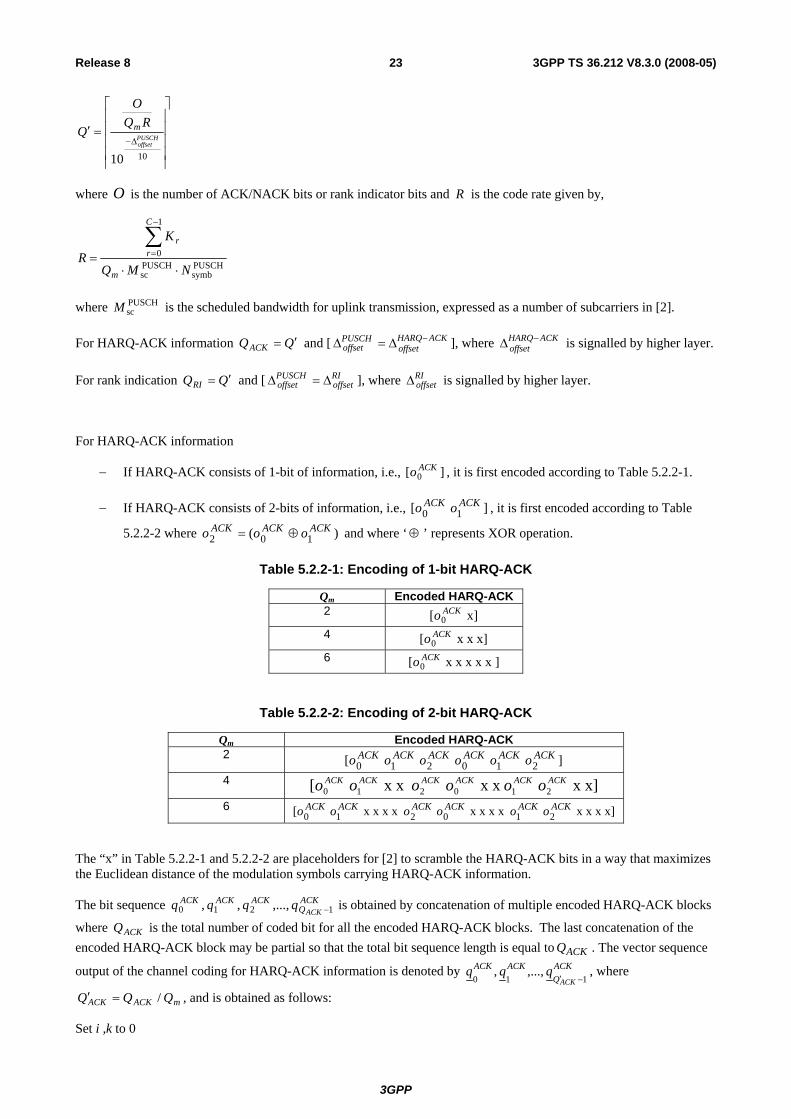
For HARQ-ACK information
− If HARQ-ACK consists of 1-bit of information, i.e., ][ 0ACKo , it is first encoded according to Table 5.2.2-1.
− If HARQ-ACK consists of 2-bits of information, i.e., ] [ 10ACKACK oo , it is first encoded according to Table
5.2.2-2 where ) ( 102ACKACKACK ooo ⊕= and where ‘⊕ ’ represents XOR operation.
Table 5.2.2-1: Encoding of 1-bit HARQ-ACK
Qm Encoded HARQ-ACK2 x][ 0
ACKo 4 x x x][ 0
ACKo 6 ] x x x x x[ 0
ACKo
Table 5.2.2-2: Encoding of 2-bit HARQ-ACK
Qm Encoded HARQ-ACK 2 ] [ 210210
ACKACKACKACKACKACK oooooo 4 x x] x x x x [ 210210
ACKACKACKACKACKACK oooooo 6 x x x x] x x x x x x x x [ 210210
ACKACKACKACKACKACK oooooo
The “x” in Table 5.2.2-1 and 5.2.2-2 are placeholders for [2] to scramble the HARQ-ACK bits in a way that maximizes the Euclidean distance of the modulation symbols carrying HARQ-ACK information.
The bit sequence ACKQ
ACKACKACKACK
qqqq 1210 ,...,,, − is obtained by concatenation of multiple encoded HARQ-ACK blocks
where ACKQ is the total number of coded bit for all the encoded HARQ-ACK blocks. The last concatenation of the encoded HARQ-ACK block may be partial so that the total bit sequence length is equal to ACKQ . The vector sequence
output of the channel coding for HARQ-ACK information is denoted by ACKQ
ACKACK
ACKqqq
110,...,,
−′, where
mACKACK QQQ /=′ , and is obtained as follows:
Set i ,k to 0
3GPP
3GPP TS 36.212 V8.3.0 (2008-05)24Release 8
while ACKQi <
TACKQi
ACKi
ACKk m
qqq ]... [ 1−+=
mQii +=
1+= kk
end while
For rank indication (RI)
− If RI consists of 1-bit of information, i.e., ][ 0RIo , it is first encoded according to Table 5.2.2-3.
− If RI consists of 2-bits of information, i.e., ] [ 10RIRI oo , it is first encoded according to Table 5.2.2-4 where
2mod) ( 102RIRIRI ooo += .
Table 5.2.2-3: Encoding of 1-bit RI
Qm Encoded RI 2 x][ 0
RIo 4 x x x][ 0
RIo 6 ] x x x x x[ 0
RIo
Table 5.2.2-4: Encoding of 2-bit RI
Qm Encoded RI 2 ] [ 210210
RIRIRIRIRIRI oooooo 4 x x] x x x x [ 210210
RIRIRIRIRIRI oooooo 6 x x x x] x x x x x x x x [ 210210
RIRIRIRIRIRI oooooo
The “x” in Table 5.2.2-3 and 5.2.2-4 are placeholders for [2] to scramble the RI bits in a way that maximizes the Euclidean distance of the modulation symbols carrying rank information.
The bit sequence RIQ
RIRIRIRI
qqqq 1210 ,...,,, − is obtained by concatenation of multiple encoded RI blocks where RIQ is
the total number of coded bit for all the encoded RI blocks. The last concatenation of the encoded RI block may be partial so that the total bit sequence length is equal to RIQ . The vector sequence output of the channel coding for rank
information is denoted by RIQ
RIRIRI
qqq110
,...,,−′
, where mRIRI QQQ /=′ , and is obtained as follows:
Set i ,k to 0
while RIQi <
TRIQi
RIi
RIk m
qqq ]... [ 1−+=
mQii +=
1+= kk
end while
For channel quality control information (CQI and/or PMI)
3GPP
3GPP TS 36.212 V8.3.0 (2008-05)25Release 8
The number of coded symbols for channel quality information is determined by
⎥⎥⎥⎥
⎥
⎤
⎢⎢⎢⎢
⎢
⎡
=Δ−
1010
PUSCHoffset
RQO
Q m
where O is the number of CQI and CRC bits, and [ CQIoffset
PUSCHoffset Δ=Δ ], where CQI
offsetΔ is signalled by higher layer.
− If the payload size is less than or equal to 11 bits, the channel coding of the channel quality information is performed according to subclause 5.2.2.6.4 with input sequence 1210 ,...,,, −Ooooo .
− For payload sizes greater than 11 bits, the CRC attachment, channel coding and rate matching of the channel quality information is performed according to subclauses 5.1.1, 5.1.3.1 and 5.1.4.2, respectively. The input bit sequence to the CRC attachment is 1210 ,...,,, −Ooooo and the CRC length is L = 8. The output bit sequence of the CRC attachment operation is the input bit sequence to the channel coding operation. The output bit sequence of the channel coding operation is the input bit sequence to the rate matching operation.
The output sequence for the channel coding of channel quality information is denoted by 13210 ,...,,,, −Qqqqqq .
5.2.2.6.1 Channel quality information formats for wideband CQI reports
Table 5.2.2.6.1-1 shows the fields and the corresponding bit widths for the channel quality information feedback for wideband reports for PDSCH transmissions over closed-loop spatial multiplexing. N in Table 5.2.2.6.1-1 is defined in subclause 7.2 [3].
Table 5.2.2.6.1-1: Fields for channel quality information (CQI) feedback for wideband CQI reports (closed loop spatial multiplexing PDSCH transmission)
The channel quality bits in Table 5.2.2.6.1-1 form the bit sequence 1210 ,...,,, −Ooooo with 0o corresponding to the first bit of the first field in the table, 1o corresponding to the second bit of the first field in the table, and 1−Oo corresponding to the last bit in the last field in the table. The field of PMI shall be in the increasing order of the subband index [3]. The first bit of each field corresponds to MSB and the last bit LSB.
5.2.2.6.2 Channel quality information formats for higher layer configured subband CQI reports
Table 5.2.2.6.2-1 shows the fields and the corresponding bit widths for the channel quality information feedback for higher layer configured report for PDSCH transmissions over single antenna port, transmit diversity and open loop spatial multiplexing. N in Table 5.2.2.6.2-1 is defined in subclause 7.2 [3].
Table 5.2.2.6.2-1: Fields for channel quality information (CQI) feedback for higher layer configured subband CQI reports
(single antenna port, transmit diversity and open loop spatial multiplexing PDSCH transmission)
The channel quality bits in Table 5.2.2.6.2-1 through Table 5.2.2.6.2-2 form the bit sequence 1210 ,...,,, −Ooooo with 0o corresponding to the first bit of the first field in each of the tables, 1o corresponding to the second bit of the first field in each of the tables, and 1−Oo corresponding to the last bit in the last field in each of the tables. The field of the PMI and subband differential CQI shall be in the increasing order of the subband index [3]. The first bit of each field corresponds to MSB and the last bit LSB.
5.2.2.6.3 Channel quality information formats for UE selected subband CQI reports
Table 5.2.2.6.3-1 shows the fields and the corresponding bit widths for the channel quality information feedback for UE selected subband CQI for PDSCH transmissions over single antenna port, transmit diversity and open loop spatial multiplexing. L in Table 5.2.2.6.3-1 is defined in subclause 7.2 [3].
Table 5.2.2.6.3-1: Fields for channel quality information (CQI) feedback for UE selected subband CQI reports
(single antenna port, transmit diversity and open loop spatial multiplexing PDSCH transmission)
Position of the M selected subbands L Table 5.2.2.6.3-2 shows the fields and the corresponding bit widths for the channel quality information feedback for UE selected subband CQI for PDSCH transmissions over closed loop spatial multiplexing. L in Table 5.2.2.6.3-2 is defined in subclause 7.2 [3].
Table 5.2.2.6.3-2: Fields for channel quality information (CQI) feedback for UE selected subband CQI reports
Subband differential CQI codeword 1 0 2 0 2 Position of the M selected subbands L L L L
Precoding matrix indication 4 2 8 8 The channel quality bits in Table 5.2.2.6.3-1 through Table 5.2.2.6.3-2 form the bit sequence 1210 ,...,,, −Ooooo with 0o corresponding to the first bit of the first field in each of the tables, 1o corresponding to the second bit of the first field in each of the tables, and 1−Oo corresponding to the last bit in the last field in each of the tables. The field of PMI shall be in the increasing order of the subband index [3], wideband PMI followed by the PMI for the M selected subband. The first bit of each field corresponds to MSB and the last bit LSB.
3GPP
3GPP TS 36.212 V8.3.0 (2008-05)27Release 8
5.2.2.6.4 Channel coding for CQI/PMI information in PUSCH
The channel quality bits input to the channel coding block are denoted by 13210 ,...,,,, −Oooooo where O is the number of bits. The number of channel quality bits depends on the transmission format as indicated in subclause 5.2.3.3.1 for wideband reports and in subclause 5.2.3.3.2 for UE-selected subbands reports.
The channel quality indication is first coded using a (32, O) block code. The code words of the (32, O) block code are a linear combination of the 11 basis sequences denoted Mi,n and defined in Table 5.2.2.6.4-1.
Table 5.2.2.6.4-1: Basis sequences for (32, O) code
The encoded CQI/PMI block is denoted by 13210 ,...,,,, −Bbbbbb where 32=B and
( )∑−
=⋅=
1
0, 2mod
O
nnini Mob where i = 0, 1, 2, …, B-1.
The output bit sequence 13210 ,...,,,, −Qqqqqq is obtained by circular repetition of the encoded CQI/PMI block as follows
( )Bii bq mod= where i = 0, 1, 2, …, Q-1.
3GPP
3GPP TS 36.212 V8.3.0 (2008-05)28Release 8
5.2.2.7 Data and control multiplexing
The control and data multiplexing is performed such that HARQ-ACK information is present on both slots and is mapped to resources around the demodulation reference signals. In addition, the multiplexing ensures that control and data information are mapped to different modulation symbols.
The inputs to the data and control multiplexing are the coded bits of the control information denoted by 13210 ,...,,,, −Qqqqqq and the coded bits of the UL-SCH denoted by 13210 ,...,,,, −Gfffff . The output of the data and
control multiplexing operation is denoted by 13210
,...,,,,−′H
ggggg , where ( )QGH += and mQHH /=′ , and
wherei
g , 1,...,0 −′= Hi are column vectors of length mQ . H is the total number of coded bits allocated for UL-SCH
data and CQI/PMI data.
Denote the number of SC-FDMA symbols per subframe for PUSCH transmission by ( )( )SRSNNN −−⋅= 12 ULsymb
PUSCHsymb .
The control information and the data shall be multiplexed as follows:
Set i, j, k to 0
while Qj < -- first place the control information
TQjjk m
qqg ] ... [ 1−+=
mQjj +=
1+= kk
end while
while Gi < -- then place the data
TQiik m
ffg ] ... [ 1−+=
mQii +=
1+= kk
end while
5.2.2.8 Channel interleaver
The channel interleaver described in this subclause in conjunction with the resource element mapping for PUSCH in [2] implements a time-first mapping of modulation symbols onto the transmit waveform while ensuring that the HARQ-ACK information is present on both slots in the subframe and is mapped to resources around the uplink demodulation reference signals.
The input to the channel interleaver are denoted by 1210
,...,,,−′H
gggg , RIQ
RIRIRIRI
qqqq 1210 ,...,,,−′ and
ACKQ
ACKACKACK
ACKqqqq
1210,...,,,
−′. The number of modulation symbols in the subframe is given by '" RIQHH +′= .. The
output bit sequence from the channel interleaver is derived as follows:
(1) Assign PUSCHsymbNCmux = to be the number of columns of the matrix. The columns of the matrix are numbered 0,
1, 2,…, 1−muxC from left to right.
(2) The number of rows of the matrix is ( ) muxmmux CQHR /"⋅= and we define mmuxmux QRR /=′ .
The rows of the rectangular matrix are numbered 0, 1, 2,…, 1−muxR from top to bottom.
3GPP
3GPP TS 36.212 V8.3.0 (2008-05)29Release 8
(3) If rank information is transmitted in this subframe, the vector sequence RIQ
RIRIRIRI
qqqq 1210 ,...,,,−′ is written onto
the columns indicated by Table 5.2.2.8-1, and by sets of Qm rows starting from the last row and moving upwards according to the following pseudocode.
Set i, j to 0.
Set r to 1−′muxR
while i < RIQ′
( )jcRI SetColumn =
RIicCr qy
RImux=
+×
1+= ii
⎣ ⎦41 iRr mux −−′=
( ) 4mod3+= jj
end while
(4) Write the input vector sequence, i.e., kk
gy = for k = 0, 1,…, 1−′H , into the ( )muxmux CR × matrix by sets of
Qm rows starting with the vector 0
y in column 0 and rows 0 to ( )1−mQ and skipping the matrix entries that are
already occupied:
⎥⎥⎥⎥⎥
⎦
⎤
⎢⎢⎢⎢⎢
⎣
⎡
−×′+×−′+×−′×−′
−++
−
)1(2)1(1)1()1(
1221
1210
muxmuxmuxmuxmuxmuxmuxmux
muxmuxmuxmux
mux
CRCRCRCR
CCCC
C
yyyy
yyyy
yyyy
L
MOMMM
L
L
(5) If HARQ-ACK information is transmitted in this subframe, the vector sequence ACKQ
ACKACKACK
ACKqqqq
1210,...,,,
−′
is written onto the columns indicated by Table 5.2.2.8-2, and by sets of Qm rows starting from the last row and moving upwards according to the following pseudocode. Note that this operation overwrites some of the channel interleaver entries obtained in step (4).
Set i, j to 0.
Set r to 1−′muxR
while i < ACKQ′
( )jc ACK ColumnSet=
ACKicCr
qyACKmux
=+×
1+= ii
⎣ ⎦41 iRr mux −−′=
( ) 4mod3+= jj
end while
3GPP
3GPP TS 36.212 V8.3.0 (2008-05)30Release 8
Where ColumnSet is given in Table 5.2.2.8-1 and indexed left to right from 0 to 3.
(6) The output of the block interleaver is the bit sequence read out column by column from the ( )muxmux CR × matrix.
The bits after channel interleaving are denoted by 1210 ,...,,, −+ RIQHhhhh .
Table 5.2.2.8-1: Column set for Insertion of rank information
CP configuration Column Set Normal {1, 4, 7, 10} Extended {0, 3, 5, 8}
Table 5.2.2.8-2: Column set for Insertion of HARQ-ACK information
CP configuration Column Set Normal {2, 3, 8, 9} Extended {1, 2, 6, 7}
5.2.3 Uplink control information on PUCCH Data arrives to the coding unit in form of indicators for measurement indication, scheduling request and HARQ acknowledgement.
Three forms of channel coding are used, one for the channel quality information (CQI), another for HARQ-ACK (acknowledgement) and scheduling request and another for combination of channel quality information (CQI) and HARQ-ACK.
110 ,...,, −Aaaa
110 ,...,, −Bbbb
Figure 5.2.3-1: Processing for UCI
5.2.3.1 Channel coding for UCI HARQ-ACK
The HARQ acknowledgement bits are received from higher layers. Each positive acknowledgement (ACK) is encoded as a binary ‘0’ and each negative acknowledgement (NAK) is encoded as a binary ‘1’. The HARQ-ACK bits are processed according to [2].
5.2.3.2 Channel coding for UCI scheduling request
The scheduling request indication is received from higher layers and is processed according to [2].
5.2.3.3 Channel coding for UCI channel quality information
The channel quality bits input to the channel coding block are denoted by 13210 ,...,,,, −Aaaaaa where A is the number of bits. The number of channel quality bits depends on the transmission format as indicated in subclause 5.2.3.3.1 for wideband reports and in subclause 5.2.3.3.2 for UE-selected subbands reports.
3GPP
3GPP TS 36.212 V8.3.0 (2008-05)31Release 8
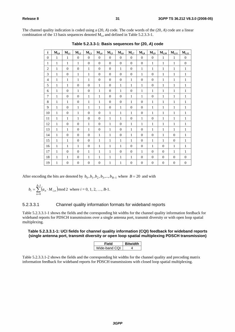
The channel quality indication is coded using a (20, A) code. The code words of the (20, A) code are a linear combination of the 13 basis sequences denoted Mi,n and defined in Table 5.2.3.3-1.
After encoding the bits are denoted by 13210 ,...,,,, −Bbbbbb where 20=B and with
( )∑−
=
⋅=1
0, 2mod
A
nnini Mab where i = 0, 1, 2, …, B-1.
5.2.3.3.1 Channel quality information formats for wideband reports
Table 5.2.3.3.1-1 shows the fields and the corresponding bit widths for the channel quality information feedback for wideband reports for PDSCH transmissions over a single antenna port, transmit diversity or with open loop spatial multiplexing.
Table 5.2.3.3.1-1: UCI fields for channel quality information (CQI) feedback for wideband reports (single antenna port, transmit diversity or open loop spatial multiplexing PDSCH transmission)
Field BitwidthWide-band CQI 4
Table 5.2.3.3.1-2 shows the fields and the corresponding bit widths for the channel quality and precoding matrix information feedback for wideband reports for PDSCH transmissions with closed loop spatial multiplexing.
3GPP
3GPP TS 36.212 V8.3.0 (2008-05)32Release 8
Table 5.2.3.3.1-2: UCI fields for channel quality and precoding information (CQI/PMI) feedback for wideband reports (closed loop spatial multiplexing PDSCH transmission)
Table 5.2.3.3.1-3 shows the fields and the corresponding bit widths for the rank indication feedback for wideband reports for PDSCH transmissions for open and closed loop spatial multiplexing.
Table 5.2.3.3.1-3: UCI fields for rank indication (RI) feedback for wideband reports
Bitwidths 4 antenna ports Field 2 antenna ports Max 2 layers Max 4 layers
Rank indication 1 1 2 The channel quality bits in Table 5.2.3.3.1-1 through Table 5.2.3.3.1-3 form the bit sequence 13210 ,...,,,, −Aaaaaa with 0a corresponding to the first bit of the first field in each of the tables, 1a corresponding to the second bit of the first field in each of the tables, and 1−Aa corresponding to the last bit in the last field in each of the tables. The first bit of each field corresponds to MSB and the last bit LSB.
5.2.3.3.2 Channel quality information formats for UE-selected sub-band reports
Table 5.2.3.3.2-1 shows the fields and the corresponding bit widths for the sub-band channel quality information feedback for UE-selected sub-band reports for PDSCH transmissions over a single antenna port, transmit diversity or with open loop spatial multiplexing.
Table 5.2.3.3.2-1: UCI fields for channel quality information (CQI) feedback for UE-selected sub-band reports (single antenna port, transmit diversity or open loop spatial multiplexing PDSCH
transmission)
Field BitwidthSub-band CQI 4 Sub-band label 1 or 2
Table 5.2.3.3.2-2 shows the fields and the corresponding bit widths for the sub-band channel quality information feedback for UE-selected sub-band reports for PDSCH transmissions with closed loop spatial multiplexing.
Table 5.2.3.3.2-2: UCI fields for channel quality information (CQI) feedback for UE-selected sub-band reports (closed loop spatial multiplexing PDSCH transmission)
Spatial differential CQI 0 3 0 3 Sub-band label 1 or 2 1 or 2 1 or 2 1 or 2
Table 5.2.3.3.2-3 shows the fields and the corresponding bit widths for the wide-band channel quality and precoding matrix information feedback for UE-selected sub-band reports for PDSCH transmissions with closed loop spatial multiplexing.
3GPP
3GPP TS 36.212 V8.3.0 (2008-05)33Release 8
Table 5.2.3.3.2-3: UCI fields for channel quality and precoding information (CQI/PMI) feedback for UE-selected sub-band reports (closed loop spatial multiplexing PDSCH transmission)
Table 5.2.3.3.2-4 shows the fields and the corresponding bit widths for the rank indication feedback for UE-selected sub-band reports for PDSCH transmissions for open and closed loop spatial multiplexing.
Table 5.2.3.3.2-4: UCI fields for rank indication (RI) feedback for UE-selected sub-band reports
Bitwidths 4 antenna ports Field 2 antenna ports Max 2 layers Max 4 layers
Rank indication 1 1 2 The channel quality bits in Table 5.2.3.3.2-1 through Table 5.2.3.3.2-4 form the bit sequence 13210 ,...,,,, −Aaaaaa with 0a corresponding to the first bit of the first field in each of the tables, 1a corresponding to the second bit of the first field in each of the tables, and 1−Aa corresponding to the last bit in the last field in each of the tables. The first bit of each field corresponds to MSB and the last bit LSB.
5.2.3.4 Channel coding for UCI channel quality information and HARQ-ACK
This section defines the channel coding scheme for the simultaneous transmission of channel quality information and HARQ-ACK information in a subframe.
When normal CP is used for uplink transmission, the channel quality information is coded according to subclause 5.2.3.3 with input bit sequence 13210 ,...,,,, −′′′′′′ Aaaaaa and output bit sequence 13210 ,...,,,, −′′′′′′ Bbbbbb , where 20=′B . The HARQ acknowledgement bits are denoted by 0a ′′ in case one HARQ acknowledgement bit or 10 ,aa ′′′′ in case two HARQ acknowledgement bits are reported per subframe. Each positive acknowledgement (ACK) is encoded as a binary ‘0’ and each negative acknowledgement (NAK) is encoded as a binary ‘1’.
The output of this channel coding block for normal CP is denoted by 13210 ,...,,,, −Bbbbbb , where
1,...,0 , −′=′= Bibb ii
In case one HARQ acknowledgement bit is reported per subframe:
0abB ′′=′ and ( )1+′= BB
In case two HARQ acknowledgement bits are reported per subframe:
110 , abab BB ′′=′′= +′′ and ( )2+′= BB
When extended CP is used for uplink transmission, the channel quality information and the HARQ-ACK acknowledgement bits are jointly coded. The HARQ acknowledgement bits are denoted by 0a ′′ in case one HARQ acknowledgement bit or [ ]10 , aa ′′′′ in case two HARQ acknowledgement bits are reported per subframe.
The channel quality information denoted by 13210 ,...,,,, −′′′′′′ Aaaaaa is multiplexed with the HARQ acknowledgement bits to yield the sequence 13210 ,...,,,, −Aaaaaa as follows
1,...,0 , −′=′= Aiaa ii
and
0aa A ′′=′ and ( )1+′= AA in case one HARQ-acknowledgement bit is reported per subframe, or
3GPP
3GPP TS 36.212 V8.3.0 (2008-05)34Release 8
0aa A ′′=′ , ( ) 11 aa A ′′=+′ and ( )2+′= AA in case two HARQ-acknowledgement bits are reported per subframe.
The sequence 13210 ,...,,,, −Aaaaaa is encoded according to section 5.2.3.3 to yield the output bit sequence
13210 ,...,,,, −Bbbbbb where 20=B .
5.2.4 Uplink control information on PUSCH without UL-SCH data When control data are sent via PUSCH without UL-SCH data, the following coding steps can be identified:
− Channel coding of control information
− Control information mapping
− Channel interleaver
5.2.4.1 Channel coding of control information
Control data arrives at the coding unit in the form of channel quality information (CQI and/or PMI), HARQ-ACK and rank indication. Different coding rates for the control information are achieved by allocating different number of coded symbols for its transmission. The channel coding and rate matching of the control data is performed according to subclause 5.2.2.6. The coded output sequence for channel quality information is denoted by 13210 ,...,,,, −Qqqqqq , the
coded vector sequence output for HARQ-ACK is denoted by ACKQ
ACKACKACK
ACKqqqq
1210,...,,,
−′ and the coded vector
sequence output for rank indication is denoted by RIQ
RIRIRI
RIqqqq
1210,...,,,
−′.
5.2.4.2 Control information mapping
The input are the coded bits of the channel quality information denoted by 13210 ,...,,,, −Qqqqqq . The output is denoted
by 13210
,...,,,,−′H
ggggg , where QH = and mQHH /=′ , and wherei
g , 1,...,0 −′= Hi are column vectors of
length mQ .
Denote the number of SC-FDMA symbols per subframe for PUSCH transmission by ( )( )SRSNNN −−⋅= 12 ULsymb
PUSCHsymb .
The control information shall be mapped as follows:
Set j, k to 0
while Qj <
TQjjk m
qqg ] ... [ 1−+=
mQjj +=
1+= kk
end while
5.2.4.3 Channel interleaver
The vector sequences 1210
,...,,,−′H
gggg , RIQ
RIRIRIRI
qqqq 1210 ,...,,,−′ and ACK
QACKACKACK
ACKqqqq
1210,...,,,
−′ are channel
interleaved according subclause 5.2.2.8. The bits after channel interleaving are denoted by 1210 ,...,,, −+ RIQHhhhh .
3GPP
3GPP TS 36.212 V8.3.0 (2008-05)35Release 8
5.3 Downlink transport channels and control information
5.3.1 Broadcast channel Figure 5.3.1-1 shows the processing structure for the BCH transport channel. Data arrives to the coding unit in form of a maximum of one transport block every transmission time interval (TTI) of 40ms. The following coding steps can be identified:
− Add CRC to the transport block
− Channel coding
− Rate matching
The coding steps for BCH transport channel are shown in the figure below.
110 ,...,, −Aaaa
110 ,...,, −Kccc
110 ,...,, −Eeee
)(1
)(1
)(0 ,...,, i
Dii
rddd −
Figure 5.3.1-1: Transport channel processing for BCH
5.3.1.1 Transport block CRC attachment
Error detection is provided on BCH transport blocks through a Cyclic Redundancy Check (CRC).
The entire transport block is used to calculate the CRC parity bits. Denote the bits in a transport block delivered to layer 1 by 13210 ,...,,,, −Aaaaaa , and the parity bits by 13210 ,...,,,, −Lppppp . A is the size of the transport block and L is the number of parity bits.
The parity bits are computed and attached to the BCH transport block according to subclause 5.1.1 setting L to 16 bits. After the attachment, the CRC bits are scrambled according to the eNode-B transmit antenna configuration with the sequence 15,1,0, ,...,, antantant xxx as indicated in Table 5.3.1.1-1 to form the sequence of bits 13210 ,...,,,, −Kccccc where
kk ac = for k = 0, 1, 2, …, A-1
( ) 2mod, AkantAkk xpc −− += for k = A, A+1, A+2,..., A+15.
3GPP
3GPP TS 36.212 V8.3.0 (2008-05)36Release 8
Table 5.3.1.1-1: CRC mask for PBCH
Number of transmit antenna ports at eNode-B PBCH CRC mask >< 15,1,0, ,...,, antantant xxx
Information bits are delivered to the channel coding block. They are denoted by 13210 ,...,,,, −Kccccc , where K is the number of bits, and they are tail biting convolutionally encoded according to subclause 5.1.3.1.
After encoding the bits are denoted by )(1
)(3
)(2
)(1
)(0 ,...,,,, i
Diiii ddddd − , with 2 and ,1,0=i , and where D is the number of bits
on the i-th coded stream, i.e., KD = .
5.3.1.3 Rate matching
A tail biting convolutionally coded block is delivered to the rate matching block. This block of coded bits is denoted by )(
1)(
3)(
2)(
1)(
0 ,...,,,, iD
iiii ddddd − , with 2 and ,1,0=i , and where i is the coded stream index and D is the number of bits in each coded stream. This coded block is rate matched according to subclause 5.1.4.2.
After rate matching, the bits are denoted by 13210 ,...,,,, −Eeeeee , where E is the number of rate matched bits.
5.3.2 Downlink shared channel, Paging channel and Multicast channel Figure 5.3.2-1 shows the processing structure for the DL-SCH, PCH and MCH transport channels. Data arrives to the coding unit in form of a maximum of one transport block every transmission time interval (TTI). The following coding steps can be identified:
− Add CRC to the transport block
− Code block segmentation and code block CRC attachment
− Channel coding
− Rate matching
− Code block concatenation
The coding steps for DL-SCH, PCH and MCH transport channels are shown in the figure below.
3GPP
3GPP TS 36.212 V8.3.0 (2008-05)37Release 8
Channel coding
Rate matching
Code block concatenation
110 ,...,, −Aaaa
110 ,...,, −Bbbb
( )110 ,...,, −rKrrr ccc
( ))(
1)(
1)(
0 ,...,, iDr
ir
ir r
ddd −
( )110 ,...,, −rErrr eee
110 ,...,, −Gfff
Transport block CRC attachment
Code block segmentationCode block CRC attachment
Figure 5.3.2-1: Transport channel processing for DL-SCH, PCH and MCH
5.3.2.1 Transport block CRC attachment
Error detection is provided on transport blocks through a Cyclic Redundancy Check (CRC).
The entire transport block is used to calculate the CRC parity bits. Denote the bits in a transport block delivered to layer 1 by 13210 ,...,,,, −Aaaaaa , and the parity bits by 13210 ,...,,,, −Lppppp . A is the size of the transport block and L is the number of parity bits.
The parity bits are computed and attached to the transport block according to subclause 5.1.1 setting L to 24 bits and using the generator polynomial gCRC24A(D).
5.3.2.2 Code block segmentation and code block CRC attachment
The bits input to the code block segmentation are denoted by 13210 ,...,,,, −Bbbbbb where B is the number of bits in the transport block (including CRC).
Code block segmentation and code block CRC attachment are performed according to subclause 5.1.2.
The bits after code block segmentation are denoted by ( )13210 ,...,,,, −rKrrrrr ccccc , where r is the code block number and Kr is the number of bits for code block number r.
5.3.2.3 Channel coding
Code blocks are delivered to the channel coding block. They are denoted by ( )13210 ,...,,,, −rKrrrrr ccccc , where r is the code block number, and Kr is the number of bits in code block number r. The total number of code blocks is denoted by C and each code block is individually turbo encoded according to subclause 5.1.3.2.
3GPP
3GPP TS 36.212 V8.3.0 (2008-05)38Release 8
After encoding the bits are denoted by ( ))(
1)(
3)(
2)(
1)(
0 ,...,,,, iDr
ir
ir
ir
ir r
ddddd − , with 2 and ,1,0=i , and where rD is the number of
bits on the i-th coded stream for code block number r, i.e. 4+= rr KD .
5.3.2.4 Rate matching
Turbo coded blocks are delivered to the rate matching block. They are denoted by ( ))(
1)(
3)(
2)(
1)(
0 ,...,,,, iDr
ir
ir
ir
ir r
ddddd − ,
with 2 and ,1,0=i , and where r is the code block number, i is the coded stream index, and rD is the number of bits in each coded stream of code block number r. The total number of code blocks is denoted by C and each coded block is individually rate matched according to subclause 5.1.4.1.
After rate matching, the bits are denoted by ( )13210 ,...,,,, −rErrrrr eeeee , where r is the coded block number, and where
rE is the number of rate matched bits for code block number r.
5.3.2.5 Code block concatenation
The bits input to the code block concatenation block are denoted by ( )13210 ,...,,,, −rErrrrr eeeee for 1,...,0 −= Cr and
where rE is the number of rate matched bits for the r-th code block.
Code block concatenation is performed according to subclause 5.1.5.2.
The bits after code block concatenation are denoted by 13210 ,...,,,, −Gfffff , where G is the total number of coded bits for transmission.
5.3.3 Downlink control information A DCI transports downlink or uplink scheduling information, or uplink power control commands for one MAC ID. The MAC ID is implicitly encoded in the CRC.
Figure 5.3.3-1 shows the processing structure for the DCI. The following coding steps can be identified:
− Information element multiplexing
− CRC attachment
− Channel coding
− Rate matching
The coding steps for DCI are shown in the figure below.
3GPP
3GPP TS 36.212 V8.3.0 (2008-05)39Release 8
CRC attachment
Channel coding
Rate matching
110 ,...,, −Aaaa
110 ,...,, −Kccc
)(1
)(1
)(0 ,...,, i
Dii ddd −
110 ,...,, −Eeee
Figure 5.3.3-1: Processing for DCI
5.3.3.1 DCI formats
The ordering of the information bits in the payload description below starts with 0a and ends with 1−Aa .
The information fields are multiplexed according to the order they are listed in each DCI format. The first bit of each information field corresponds to MSB.
5.3.3.1.1 Format 0
DCI format 0 is used for the scheduling of PUSCH.
The following information is transmitted by means of the DCI format 0:
- Flag for format0/format1A differentiation – 1 bit
- NUL_hop bits are used to obtain the value of )(~ inPRB as indicated in subclause [8.4] of [3]
- ⎡ ⎤ ⎟⎠⎞⎜
⎝⎛ −+ UL_hop
ULRB
ULRB2 )2/)1((log NNN bits provide the resource allocation of the first slot in the UL
subframe
- For non-hopping PUSCH:
- ⎡ ⎤ ⎟⎠⎞⎜
⎝⎛ + )2/)1((log UL
RBULRB2 NN bits provide the resource allocation of the first slot in the UL subframe
- Modulation and coding scheme and redundancy version – 5 bits
- New data indicator – 1 bit
- TPC command for scheduled PUSCH – 2 bits
- Cyclic shift for DM RS – 3 bits
3GPP
3GPP TS 36.212 V8.3.0 (2008-05)40Release 8
- UL index (2 bits, this field just applies to TDD operation)
- CQI request – 1 bit
If the number of information bits in format 0 is less than for format 1A, zeros shall be appended to format 0 until the payload size equals that of format 1A.
5.3.3.1.2 Format 1
DCI format 1 is used for the scheduling of one PDSCH codeword.
The following information is transmitted by means of the DCI format 1:
- Resource allocation header (resource allocation type 0 / type 1) – 1 bit
- Resource block assignment:
- For resource allocation type 0 [3],
- ⎡ ⎤PN /DLRB bits provide the resource allocation
- For resource allocation type 1 [3],
- ( )⎡ ⎤P2log bits of this field are used as a header specific to this resource allocation type to indicate the selected resource blocks subset
- 1 bit indicates a shift of the resource allocation span
- ⎡ ⎤ ( )⎡ ⎤( )1log/ 2DLRB −− PPN bits provide the resource allocation
where the value of P depends on the number of DL resource blocks as indicated in subclause [7.1.1] of [3]
- Modulation and coding scheme – 5 bits
- HARQ process number – 3 bits (FDD) , 4 bits (TDD)
- New data indicator – 1 bit
- Redundancy version – 2 bits
- TPC command for PUCCH – 2 bits
- Downlink Assignment Index (this field just applies to TDD operation) – 2 bits
5.3.3.1.3 Format 1A
DCI format 1A is used for the compact scheduling of one PDSCH codeword. DCI format 1A can be used for scheduling PDSCH to UEs configured in any transmission mode.
The following information is transmitted by means of the DCI format 1A:
- Flag for format0/format1A differentiation – 1 bit
- Localized/Distributed VRB assignment flag – 1 bit
- Resource block assignment – ⎡ ⎤)2/)1((log DLRB
DLRB2 +NN bits
- For localized VRB:
⎡ ⎤)2/)1((log DLRB
DLRB2 +NN bits provide the resource allocation
- For distributed VRB:
3GPP
3GPP TS 36.212 V8.3.0 (2008-05)41Release 8
- For 50DLRB <N
- ⎡ ⎤)2/)1((log DLRB
DLRB2 +NN bits provide the resource allocation
- For 50DLRB ≥N
- 1 bit indicates if gap,1gap NN = or gap,2gap NN =
- ⎡ ⎤ )1)2/)1((log( DLRB
DLRB2 −+NN bits provide the resource allocation
- Modulation and coding scheme – 5bits
- HARQ process number – 3 bits (FDD) , 4 bits (TDD)
- New data indicator – 1 bit
- Redundancy version – 2 bits
- TPC command for PUCCH – 2 bits
- Downlink Assignment Index (this field just applies to TDD operation) – 2 bits
If the number of information bits in format 1A is less than for format 0, zeros shall be appended to format 1A until the payload size equals that of format 0.
5.3.3.1.4 Format 1C
DCI format 1C is used for very compact assignments of DL-SCH assignments. The DL-SCH transmission shall always use QPSK modulation when format 1C is used.
The following information is transmitted by means of the DCI format 1C:
- Resource block assignment [5 bits]
- Modulation and coding scheme – 3 bits
- Redundancy version – 2 bits
5.3.3.1.5 Format 2
DCI format 2 is used for scheduling PDSCH to UEs configured in spatial multiplexing mode.
The following information is transmitted by means of the DCI format 2:
In general:
- Resource allocation header (resource allocation type 0 / type 1) – 1 bit
- Resource block assignment:
- For resource allocation type 0 [3],
- ⎡ ⎤PN /DLRB bits provide the resource allocation
- For resource allocation type 1 [3],
- ( )⎡ ⎤P2log bits of this field are used as a header specific to this resource allocation type to indicate the selected resource blocks subset
- 1 bit indicates a shift of the resource allocation span
- ⎡ ⎤ ( )⎡ ⎤( )1log/ 2DLRB −− PPN bits provide the resource allocation
3GPP
3GPP TS 36.212 V8.3.0 (2008-05)42Release 8
where the value of P depends on the number of DL resource blocks as indicated in subclause [7.1.1] of [3]
- TPC command for PUCCH – 2 bits
- Downlink Assignment Index (this field just applies to TDD operation) – 2 bits
- HARQ process number - 3 bits (FDD), 4 bits (TDD)
- HARQ swap flag – 1 bit
For codeword 1:
- Modulation and coding scheme – 5 bits
- New data indicator – 1 bit
- Redundancy version – 2 bits
For codeword 2:
- Modulation and coding scheme – 5 bits
- New data indicator – 1 bit
- Redundancy version – 2 bits
Precoding information – number of bits as specified in Table 5.3.3.1.5-1
A codeword field is also used for determining whether the corresponding codeword is enabled or disabled. The interpretation of the precoding information field depends on the number of enabled codewords according to Table 5.3.3.1.5-2, Table 5.3.3.1.5-3 and Table 5.3.3.1.5-4. Note that PMI indicates which codebook index is used in Table 6.3.4.2.3-1 or Table 6.3.4.2.3-2 of [2]. The combination of a single enabled codeword and RI=2 in Table 5.3.3.1.5-3 and Table 5.3.3.1.5-4 is only supported for retransmission of the corresponding HARQ process.
For the open-loop spatial multiplexing transmission mode with 2 antenna ports, the precoding information field is not present. The number of transmission layers, RI, is equal to 2 if both codewords are enabled; and is equal to 1 if codeword 1 is enabled while codeword 2 is disabled.
Table 5.3.3.1.5-1: Number of bits for precoding information
Transmission mode Number of antenna ports at eNode-B Closed-loop spatial
multiplexing Open-loop spatial
multiplexing 2 3 0 4 6 2
Table 5.3.3.1.5-2: Content of precoding information field for 2 antenna ports and closed-loop spatial multiplexing transmission mode
M M M M 33 RI=2: PMI=15 32 RI=3: PMI=15 34 RI=2: Precoding
according to the latest PMI report on PUSCH using the precoder(s)
indicated by the reported PMI(s)
33 RI=3: Precoding according to the latest PMI report on PUSCH using the precoder(s)
indicated by the reported PMI(s)
35 – 63 reserved 34 RI=4: PMI=0 35 RI=4: PMI=1
M M 49 RI=4: PMI=15 50 RI=4: Precoding
according to the latest PMI report on PUSCH using the precoder(s)
indicated by the reported PMI(s)
51 – 63 Reserved
3GPP
3GPP TS 36.212 V8.3.0 (2008-05)45Release 8
Table 5.3.3.1.5-4: Content of precoding information field for 4 antenna ports and open-loop spatial multiplexing transmission mode
One codeword:
Codeword 1 enabled,
Codeword 2 disabled
Two codewords:
Codeword 1 enabled,
Codeword 2 enabled Bit field
mapped to index
Message Bit field mapped to index
Message
0 RI=1: transmit diversity 0 RI=2: precoder cycling with large delay CDD
1 RI=2: precoder cycling with large delay CDD
1 RI=3: precoder cycling with large delay CDD
2 reserved 2 RI=4: precoder cycling with large delay CDD
3 reserved 3 reserved
5.3.3.1.6 Format 3
DCI format 3 is used for the transmission of TPC commands for PUCCH and PUSCH with 2-bit power adjustments.
The following information is transmitted by means of the DCI format 3:
- TPC command number 1, TPC command number 2,…, TPC command number N
where ⎥⎦
⎥⎢⎣
⎢=
20format L
N , and where 0format L is equal to the payload size of format 0 before CRC attachment.
5.3.3.1.7 Format 3A
DCI format 3A is used for the transmission of TPC commands for PUCCH and PUSCH with single bit power adjustments.
The following information is transmitted by means of the DCI format 3A:
- TPC command number 1, TPC command number 2,…, TPC command number M
where 0format LM = , and where 0format L is equal to the payload size of format 0 before CRC attachment.
5.3.3.2 CRC attachment
Error detection is provided on DCI transmissions through a Cyclic Redundancy Check (CRC).
The entire PDCCH payload is used to calculate the CRC parity bits. Denote the bits of the PDCCH payload by 13210 ,...,,,, −Aaaaaa , and the parity bits by 13210 ,...,,,, −Lppppp . A is the PDCCH payload size and L is the number of parity bits.
The parity bits are computed and attached according to subclause 5.1.1 setting L to 16 bits, resulting in the sequence 13210 ,...,,,, −Bbbbbb , where B = A+ L.
In the case where UE transmit antenna selection is not configured or applicable, after attachment, the CRC parity bits are scrambled with the UE identity 15,1,0, ,...,, ueueue xxx to form the sequence of bits 13210 ,...,,,, −Bccccc . The relation between ck and bk is:
kk bc = for k = 0, 1, 2, …, A-1
3GPP
3GPP TS 36.212 V8.3.0 (2008-05)46Release 8
( ) 2mod, Akuekk xbc −+= for k = A, A+1, A+2,..., A+15.
In the case where UE transmit antenna selection is configured and applicable, after attachment, the CRC parity bits are scrambled with the Antenna selection mask ,0 ,1 ,15, ,...,AS AS ASx x x as indicated in Table 5.3.3.2-1 and the UE identity
15,1,0, ,...,, ueueue xxx to form the sequence of bits 13210 ,...,,,, −Bccccc . The relation between ck and bk is:
kk bc = for k = 0, 1, 2, …, A-1
( ), , mod 2k k ue k A AS k Ac b x x− −= + + for k = A, A+1, A+2,..., A+15.
Information bits are delivered to the channel coding block. They are denoted by 13210 ,...,,,, −Kccccc , where K is the number of bits, and they are tail biting convolutionally encoded according to subclause 5.1.3.1.
After encoding the bits are denoted by )(1
)(3
)(2
)(1
)(0 ,...,,,, i
Diiii ddddd − , with 2 and ,1,0=i , and where D is the number of
bits on the i-th coded stream, i.e., KD = .
5.3.3.4 Rate matching
A tail biting convolutionally coded block is delivered to the rate matching block. This block of coded bits is denoted by )(
1)(
3)(
2)(
1)(
0 ,...,,,, iD
iiii ddddd − , with 2 and ,1,0=i , and where i is the coded stream index and D is the number of bits in each coded stream. This coded block is rate matched according to subclause 5.1.4.2.
After rate matching, the bits are denoted by 13210 ,...,,,, −Eeeeee , where E is the number of rate matched bits.
5.3.4 Control format indicator Data arrives each subframe to the coding unit in the form of an indicator for the time span, in units of OFDM symbols, of the DCI in that subframe. The CFI takes values CFI = 1, 2 or 3. For system bandwidths ]10[DL
RB >N , the span of the
DCI in units of OFDM symbols, 1, 2 or 3, is given by the CFI. For system bandwidths ]10[DLRB ≤N , the span of the DCI
in units of OFDM symbols, 2, 3 or 4, is given by CFI+1.
The coding flow is shown in Figure 5.3.4-1.
3110 ,...,, bbb
Channel coding
CFI
Figure 5.3.4-1 Coding for CFI
3GPP
3GPP TS 36.212 V8.3.0 (2008-05)47Release 8
5.3.4.1 Channel coding
The control format indicator is coded according to Table 5.3.4-1.
5.3.5 HARQ indicator Data arrives to the coding unit in form of indicators for HARQ acknowledgement.
The coding flow is shown in Figure 5.3.5-1.
210 ,, bbb
Channel coding
HI
Figure 5.3.5-1 Coding for HI
5.3.5.1 Channel coding
The HARQ indicator is coded according to Table 5.3.5-1, where for a positive acknowledgement HI = 0 and for a negative acknowledgement HI = 1.
Table 5.3.5-1: HI codewords
HI
HI codeword < b0, b1, b2 >
0 < 0,0,0 >
1 < 1,1,1 >
3GPP
3GPP TS 36.212 V8.3.0 (2008-05)48Release 8
Annex A (informative): Change history
Change history Date TSG # TSG Doc. CR Rev Subject/Comment Old New 2006-09 Skeleton 0.0.02006-10 Updated skeleton 0.0.0 0.0.12006-10 Endorsed skeleton 0.0.1 0.1.02006-11 Added TC. Added Broadcast, Paging and MBMS transport
channels in Table 4.2-1. 0.1.0 0.1.1
2006-11 Endorsed v 0.2.0 0.1.1 0.2.02006-12 Added CC. Added type of coding for each transport channel or
control information. 0.2.0 0.2.1
2007-01 Editor’s version 0.2.1 0.2.22007-01 Endorsed v 0.3.0 0.2.2 0.3.02007-02 Added QPP turbo Interleaver description. 0.3.0 0.3.12007-02 Editor’s version 0.3.1 0.3.22007-02 Endorsed v 0.4.0 0.3.2 0.4.02007-02 Added CRC details for PDSCH, PDCCH and PUSCH. Added QPP
turbo-interleaver parameters. Set Z to 6144. Added details on code block segmentation.
0.4.0 0.4.1
2007-02 Editor’s version 0.4.1 0.4.22007-03 RAN#35 RP-070170 For information at RAN#35 0.4.2 1.0.02007-03 Editor’s version 1.0.0 1.0.12007-03 Editor’s version 1.0.1 1.1.02007-05 Editor’s version 1.1.0 1.1.12007-05 Editor’s version 1.1.1 1.1.22007-05 Editor’s version 1.1.2 1.2.02007-06 Added circular buffer rate matching for PDSCH and PUSCH.
Miscellaneous changes. 1.2.0 1.2.1
2007-06 Editor’s version 1.2.1 1.2.22007-07 Editor’s version 1.2.2 1.2.32007-07 Endorsed by email following decision taken at RAN1#49b 1.2.3 1.3.02007-08 Editor’s version including decision from RAN1#49bis. 1.3.0 1.3.12007-08 Editor’s version 1.3.1 1.3.22007-08 Editor’s version 1.3.2 1.4.02007-09 Editor’s version with decisions from RAN1#50 1,4.0 1,4,12007-09 Editor’s version 1.4.1 1.4.210/09/07 RAN#37 RP-070730 - - For approval at RAN#37 1.4.2 2.0.012/09/07 RAN_37 RP-070730 - - Approved version 2.0.0 8.0.028/11/07 RAN_38 RP-070949 0001 - Update of 36.212 8.0.0 8.1.005/03/08 RAN_39 RP-080145 0002 - Update to 36.212 incorporating decisions from RAN1#51bis and
RAN1#52 8.1.0 8.2.0
28/05/08 RAN_40 RP-080433 0003 - Joint coding of CQI and ACK on PUCCH 8.2.0 8.3.028/05/08 RAN_40 RP-080433 0004 1 ACK insertion into PUSCH 8.2.0 8.3.028/05/08 RAN_40 RP-080433 0005 1 Introduction of format 1C 8.2.0 8.3.028/05/08 RAN_40 RP-080433 0006 1 Miscellaneous fixes to 36.212 8.2.0 8.3.028/05/08 RAN_40 RP-080433 0008 1 On multiplexing scheme for indicators 8.2.0 8.3.028/05/08 RAN_40 RP-080433 0009 1 On the soft buffer split of MIMO and TDD 8.2.0 8.3.028/05/08 RAN_40 RP-080433 0010 - Resource assignment field for distributed VRB 8.2.0 8.3.028/05/08 RAN_40 RP-080433 0011 - Clarifying the use of the different DCI formats 8.2.0 8.3.028/05/08 RAN_40 RP-080433 0012 1 Clarifying the value of NL 8.2.0 8.3.028/05/08 RAN_40 RP-080433 0013 - Payload size for DCI formats 3 and 3A 8.2.0 8.3.028/05/08 RAN_40 RP-080433 0014 - Coding of ACK on PUSCH 8.2.0 8.3.028/05/08 RAN_40 RP-080433 0015 1 Coding of RI on PUSCH and mapping 8.2.0 8.3.028/05/08 RAN_40 RP-080433 0016 - CRC for control information on PUSCH 8.2.0 8.3.028/05/08 RAN_40 RP-080433 0017 - Introduction of Downlink Assignment Index 8.2.0 8.3.028/05/08 RAN_40 RP-080433 0018 - Coding of CQI/PMI on PUSCH coming from PUCCH 8.2.0 8.3.028/05/08 RAN_40 RP-080433 0019 - Simultaneous transmission of aperiodic CQI and UL control 8.2.0 8.3.028/05/08 RAN_40 RP-080433 0020 - Encoding of antenna indicator on DCI format 0 8.2.0 8.3.028/05/08 RAN_40 RP-080433 0021 - PDCCH coverage in narrow bandwidths 8.2.0 8.3.028/05/08 RAN_40 RP-080433 0022 - Closed-loop and open-loop spatial multiplexing 8.2.0 8.3.028/05/08 RAN_40 RP-080457 0023 - Formula for linkage between PUSCH MCS and amount of