www.msp430.ubi.pt Copyright 2009 Texas Instruments, All Rights Reserved 3-1 Chapter 3 3.Hardware Development Tools The aim of this chapter is to describe the MSP430 hardware development tools. During the chapters that follow, the laboratories will be supported by either one of two platforms. Depending on the specific peripheral that will be studied, it will use the eZ430- F2013/eZ430-RF2500 MSP430 USB Stick Development Tool and/or the MSP430FG4618/F2013 Experimenter’s board. Some information is also provided covering the new hardware development tool that includes a MSP430x5xx device. The main features and integrated peripherals for each platform are described. Additionally, hardware development tools provided by third parties are also listed. Topic Page 3.1 Starter kit description - eZ430-F2013/eZ430-RF2500 MSP430 USB Stick Development Tool......................................... 3-3 3.1.1 eZ430-F2013 ............................................................. 3-3 3.1.2 eZ430-RF2500 ........................................................... 3-3 3.1.3 Device features and integrated peripherals ............... 3-4 3.1.4 Board features........................................................... 3-5 3.2 Starter kit description - MSP430FG4618/F2013 Experimenter’s board................................................................. 3-6 3.2.1 Device features and integrated peripherals ............... 3-7 3.2.2 Board features........................................................... 3-8 3.3 Starter kit description–MSP-EXP430F5438 demo board 3-10 3.3.1 Device features and integrated peripherals ............. 3-11 3.3.2 Board features......................................................... 3-12 3.4 MSP-FET430 Flash Emulation Tool (FET)....................... 3-14 3.4.1 Device features ....................................................... 3-14 3.4.2 Hardware Installation ............................................. 3-15 3.5 Wireless expansion (Chipcon’s RF transceiver chip) ..... 3-16 3.6 Third party hardware development tools ...................... 3-18
Transcript
www.msp430.ubi.pt Copyright 2009 Texas Instruments, All Rights Reserved 3-1
Chapter 3
3. Hardware Development Tools
The aim of this chapter is to describe the MSP430 hardware development tools. During the chapters that follow, the laboratories will be supported by either one of two platforms. Depending on the specific peripheral that will be studied, it will use the eZ430-F2013/eZ430-RF2500 MSP430 USB Stick Development Tool and/or the MSP430FG4618/F2013 Experimenter’s board. Some information is also provided covering the new hardware development tool that includes a MSP430x5xx device. The main features and integrated peripherals for each platform are described.
Additionally, hardware development tools provided by third parties are also listed.
Topic Page
3.1 Starter kit description - eZ430-F2013/eZ430-RF2500 MSP430 USB Stick Development Tool......................................... 3-3
Annex D – MSP- EXP430F5438 Experimenter board schematics3-32
Annex E – MSP-FET430 schematics...........................................3-34
Starter kit description - eZ430-F2013/eZ430-RF2500 MSP430 USB Stick Development Tool
www.msp430.ubi.pt Copyright 2009 Texas Instruments, All Rights Reserved 3-3
3.1 Starter kit description - eZ430-F2013/eZ430-RF2500 MSP430 USB Stick Development Tool
3.1.1 eZ430-F2013
The eZ430-F2013 is a MSP430 development tool used to evaluate the ‘F2013 and develop projects on hardware that is contained on a USB stick (Figure 3-1).
For software, the eZ430-F2013 uses the IAR Embedded Workbench Integrated Development Environment (IDE) to provide full emulation. The Integrated IAR Kickstart user interface provides an assembler, linker, simulator, source-level debugger and limited C-compiler. The design can be implemented as a stand-alone system or the removable target board detached to integrate into the user’s own hardware.
The USB port provides enough power to operate the MSP430 without requiring an external power supply.
All 14-pins on the MSP430F2013 are accessible on the MSP-EZ430D target board for easy debugging and interfacing to peripherals. One of these digital I/O ports is connected to an LED for visual feedback. Annex A gives the schematics for the eZ430-F2013.
Figure 3-1. eZ430-F2013 development tool.
3.1.2 eZ430-RF2500
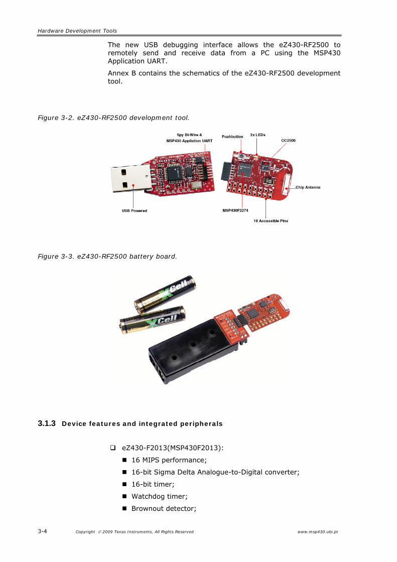
The eZ430-RF2500 is a USB-based MSP430 wireless development tool used to evaluate the MSP430F2274 microcontroller and CC2500 2.4-GHz wireless transceiver (Figure 3-2).
The eZ430-RF2500 uses the IAR Embedded Workbench Integrated Development Environment (IDE) or Code Composer Essentials (CCE) to develop an application.
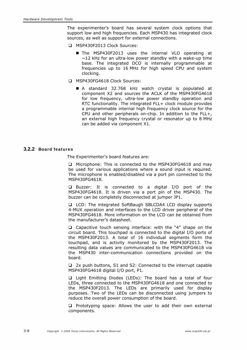
The eZ430-RF2500T target board is an out-of-the box wireless system that may be used with the USB debugging interface, as a stand-alone system, with or without external sensors, or may be incorporated into an existing user design.
Hardware Development Tools
3-4 Copyright 2009 Texas Instruments, All Rights Reserved www.msp430.ubi.pt
The new USB debugging interface allows the eZ430-RF2500 to remotely send and receive data from a PC using the MSP430 Application UART.
Annex B contains the schematics of the eZ430-RF2500 development tool.
The MSP430 experimenter’s board (shown in Figure 3-4) features a MSP430F2013 and a MSP430FG4618, and is compatible with TI’s wireless evaluation modules. The combination of these two MCUs provides nearly every peripheral available in the MSP430 family. The integrated TI wireless evaluation module header and the large amounts of RAM on the MSP430FG4618 makes it an ideal platform for wireless applications.
Two JTAG headers are accessible to program and debug each MSP430 individually. Communication is possible with external devices or between the two MSP430s. The MSP430FG4618 uses the standard 4-wire JTAG connection while the MSP430F2013 uses the Spy-Bi-wire (2-wire) JTAG interface, allowing all port pins to be used during debug. Two independent debug environments are supported: IAR Embedded Workbench and TI Code Composer Essentials (CCE).
The wide range of integrated peripherals and hardware connectivity allows extensive development possibilities and makes it an ideal platform for learning the MSP430 MCU architecture.
A TI USB Flash Emulation Tool (FET), like the MSP-FET430UIF, is required to program and debug the MSP430 devices on the experimenter board. Power may be supplied over the USB FET or from two AAA 1.5 V batteries.
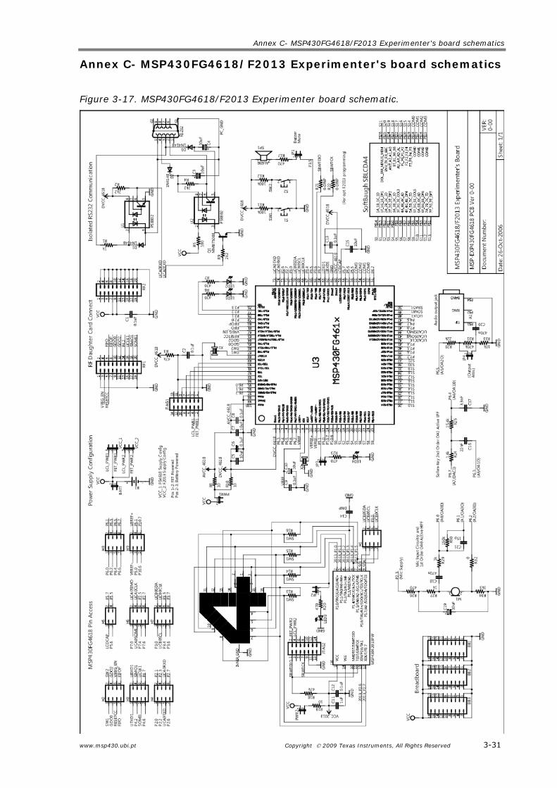
Annex C gives the schematics of the Experimenter’s board.
www.msp430.ubi.pt Copyright 2009 Texas Instruments, All Rights Reserved 3-7
3.2.1 Device features and integrated peripherals
Key Features:
MSP430 Devices:
MSP430FG4618;
MSP430F2013.
Integrated peripherals:
12-bit SAR Analogue-to-Digital Converter;
16-bit Sigma Delta Analogue-to-Digital Converter;
Operational Amplifiers;
Direct Memory Access (DMA);
Multiplier;
LCD Controller;
Communication Interfaces: SPI, UART, I2C, IrDA.
The MSP430FG4618 and the MSP430F2013 contain support for I2C and SPI protocols using the USCI and the USI peripherals. These peripherals are used for inter-processor communication. The link can be disconnected in hardware to allow the peripherals to be used for other communication purposes.
Programming and Debugging: Can be programmed using any MSP430 Flash Emulation Tool (MSP-FET430UIF)
Wireless expansion: Compatible with TI Wireless CCxxx0EMK Evaluation Modules, such as the CC2500EMK
The MSP430FG4618/F2013 experimenter’s board supports a range of applications through the use of the on-chip peripherals, connecting it to a number of on-board components and interfaces as shown in Figure 3-5.
3-8 Copyright 2009 Texas Instruments, All Rights Reserved www.msp430.ubi.pt
The experimenter’s board has several system clock options that support low and high frequencies. Each MSP430 has integrated clock sources, as well as support for external connections.
MSP430F2013 Clock Sources:
The MSP430F2013 uses the internal VLO operating at ~12 kHz for an ultra-low power standby with a wake-up time base. The integrated DCO is internally programmable at frequencies up to 16 MHz for high speed CPU and system clocking.
MSP430FG4618 Clock Sources:
A standard 32.768 kHz watch crystal is populated at component X2 and sources the ACLK of the MSP430FG4618 for low frequency, ultra-low power standby operation and RTC functionality. The integrated FLL+ clock module provides a programmable internal high frequency clock source for the CPU and other peripherals on-chip. In addition to the FLL+, an external high frequency crystal or resonator up to 8 MHz can be added via component X1.
3.2.2 Board features
The Experimenter’s board features are:
Microphone: This is connected to the MSP430FG4618 and may be used for various applications where a sound input is required. The microphone is enabled/disabled via a port pin connected to the MSP430FG4618.
Buzzer: It is connected to a digital I/O port of the MSP430FG4618. It is driven via a port pin of the MSP430. The buzzer can be completely disconnected at jumper JP1.
LCD: The integrated SoftBaugh SBLCDA4 LCD display supports 4-MUX operation and interfaces to the LCD driver peripheral of the MSP430FG4618. More information on the LCD can be obtained from the manufacturer’s datasheet.
Capacitive touch sensing interface: with the “4” shape on the circuit board. This touchpad is connected to the digital I/O ports of the MSP430F2013. A total of 16 individual segments form the touchpad, and is activity monitored by the MSP430F2013. The resulting data values are communicated to the MSP430FG4618 via the MSP430 inter-communication connections provided on the board.
2x push buttons, S1 and S2: Connected to the interrupt capable MSP430FG4618 digital I/O port, P1.
Light Emitting Diodes (LEDs): The board has a total of four LEDs, three connected to the MSP430FG4618 and one connected to the MSP430F2013. The LEDs are primarily used for display purposes. Two of the LEDs can be disconnected using jumpers to reduce the overall power consumption of the board.
Prototyping space: Allows the user to add their own external components.
www.msp430.ubi.pt Copyright 2009 Texas Instruments, All Rights Reserved 3-9
RS232 communication interface: For a serial interface to a PC, the MSP430FG4618 supports the standard RS-232 9-pin interface via its USCI peripheral, configured in UART mode.
2x JTAG programming interfaces;
3.5 mm headphone jack: This analogue output can be brought out of the board via a mono 3.5 mm jack connected to the integrated Op-Amp OA2. The input to this amplifier can be internally connected to the DAC12 output of the MSP430FG4618. Several attenuation options are provided internally and in hardware using jumper JP4.
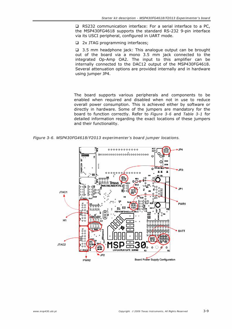
The board supports various peripherals and components to be enabled when required and disabled when not in use to reduce overall power consumption. This is achieved either by software or directly in hardware. Some of the jumpers are mandatory for the board to function correctly. Refer to Figure 3-6 and Table 3-1 for detailed information regarding the exact locations of these jumpers and their functionality.
VCC VCC_1: Lower 3 pins. Used for FG4618/JTAG1. VCC_2: Upper 3 pins. Used for F2013/JTAG2. LCL: Provide local VCC to FET interface. FET: Power board from the FET interface. (BATT should not be set)
Power source from JTAG Required for use without batteries
The MSP-EXP430F5438 Demo Board (shown in Figure 3-7) features the brand new MSP430 family, the 5xx. The MSP430 included in this board is the F5438.
Due to the new features as Power Management Module (PMM), Unified Clock System (UCS) and system (SYS) modules, expanded memory/peripheral mapping, peripheral module enhancements and enhanced performance such as 20 bit address capability and the 32 bit Hardware Multiplier, included in this family, this board provides the wide range of F5438 peripherals.
www.msp430.ubi.pt Copyright 2009 Texas Instruments, All Rights Reserved 3-11
Figure 3-7. MSP-EXP430F5438 demo board.
One JTAG header is accessible to program and debug the MSP430F5438 and allows for communication to external devices. The MSP430F5438 uses the standard 4-wire JTAG interface allowing all port pins to be used during debug. Two independent debug environments are supported: IAR Embedded Workbench and TI Code Composer Essentials (CCE).
The wide range of integrated peripherals and hardware connectivity allows extensive development possibilities and makes it the ideal learning platform the new MSP430x5xx MCU architecture.
A TI USB Flash Emulation Tool (FET), like the MSP-FET430UIF, is required to program and debug the MSP430 device on the MSP-EXP430F5438 demo board. Power may be supplied over the USB FET interface, USB interface or from the included two AA 1.5 V batteries.
In Annex D are exposed the schematics of the MSP-EXP430F5438 demo board.
3.3.1 Device features and integrated peripherals
Key Features:
Device Featured:
MSP430F5438 (256 KB+512 B flash memory; 16 KB RAM).
Integrated peripherals:
Three 16-bit timers;
12-bit SAR Analogue-to-Digital Converter;
Direct Memory Access (DMA);
Hardware Development Tools
3-12 Copyright 2009 Texas Instruments, All Rights Reserved www.msp430.ubi.pt
Universal Serial Communication Interfaces (USCI): Enhanced UART Supporting Auto-Baudrate; IrDA Encoder and Decoder; Synchronous SPI; I2C™;
Real time clock module with alarm capabilities;
Temperature sensor;
Up to 87 I/O pins.
The MSP430F5438 supports I2C and SPI protocols.
Programming and Debugging: Can be programmed using any MSP430 Flash Emulation Tool (MSP-FET430UIF);
Wireless expansion:
Compatible with TI Wireless CCxxxXEMK Evaluation Modules, such as the CC2500EMK;
Compatible with TI eZ430-RF2500.
The demo board has various system clock options that support low and high frequencies. The MSP430F5438 has integrated an Unified Clock System that provides different clock sources:
Three low-frequency sources:
LFXT1;
Internal Very Low Power/Low Frequency Oscillator (VLO);
Internal Reference Oscillator (REFO).
Internal Digitally Controlled Oscillator (DCO) / Frequency Locked Loop (FLL) for highspeed operation:
FLL reference selectable from LFXT1, REFO, or XT2.
ACLK/SMCLK/MCLK can all be driven from any source;
Dedicated MODOSC (internal) used for modules like Flash controller, ADC, among others.
3.3.2 Board features
32,768 Hz crystal oscillator;
Digital I/O ports connectors populated;
Microphone: The microphone is enabled/disabled via a port pin connected to the MSP430F5438;
LCD: The integrated Hitachi HD66753 (168 x 132-dot Graphics LCD Controller/Driver with Bit-operation Functions). More information on the LCD can be obtained from the manufacturer’s datasheet;
Joystick;
2x push buttons, S1 and S2: Connected to the interrupt capable MSP430F5438 digital I/O port, P2;
MSP-FET430 Flash Emulation Tool (FET)
www.msp430.ubi.pt Copyright 2009 Texas Instruments, All Rights Reserved 3-13
Two Light Emitting Diodes (LEDs) primarily used for display purposes. Connected to the interrupt capable MSP430F5438 digital I/O port, P1;
JTAG Programming Interface;
2 or 3-axis accelerometer (Analog Devices ADXL322/330). The 3-axis accelerometer is not populated. More information on the accelerometer can be obtained from the manufacturer’s datasheet;
3.5 mm headphone jack;
Mini USB connector;
Three Radio Frequency (RF) connectors (SPI interface). RF1 and RF2 provide connection to the TI’s wireless evaluation modules header: CCxxxXEMK boards. RF3 provides connection to the eZ430-RF2500.
The board supports various peripherals and components to be enabled when required and disabled when not in use to reduce overall power consumption. This is achieved either by software or directly in hardware. Some of the jumpers are mandatory for the board to function correctly. Refer to Figure 3-8 for detailed information regarding the exact locations of these jumpers and their functionality.
Figure 3-8. MSP-EXP430F5438 demo board jumper and connectors locations.
Hardware Development Tools
3-14 Copyright 2009 Texas Instruments, All Rights Reserved www.msp430.ubi.pt
3.4 MSP-FET430 Flash Emulation Tool (FET)
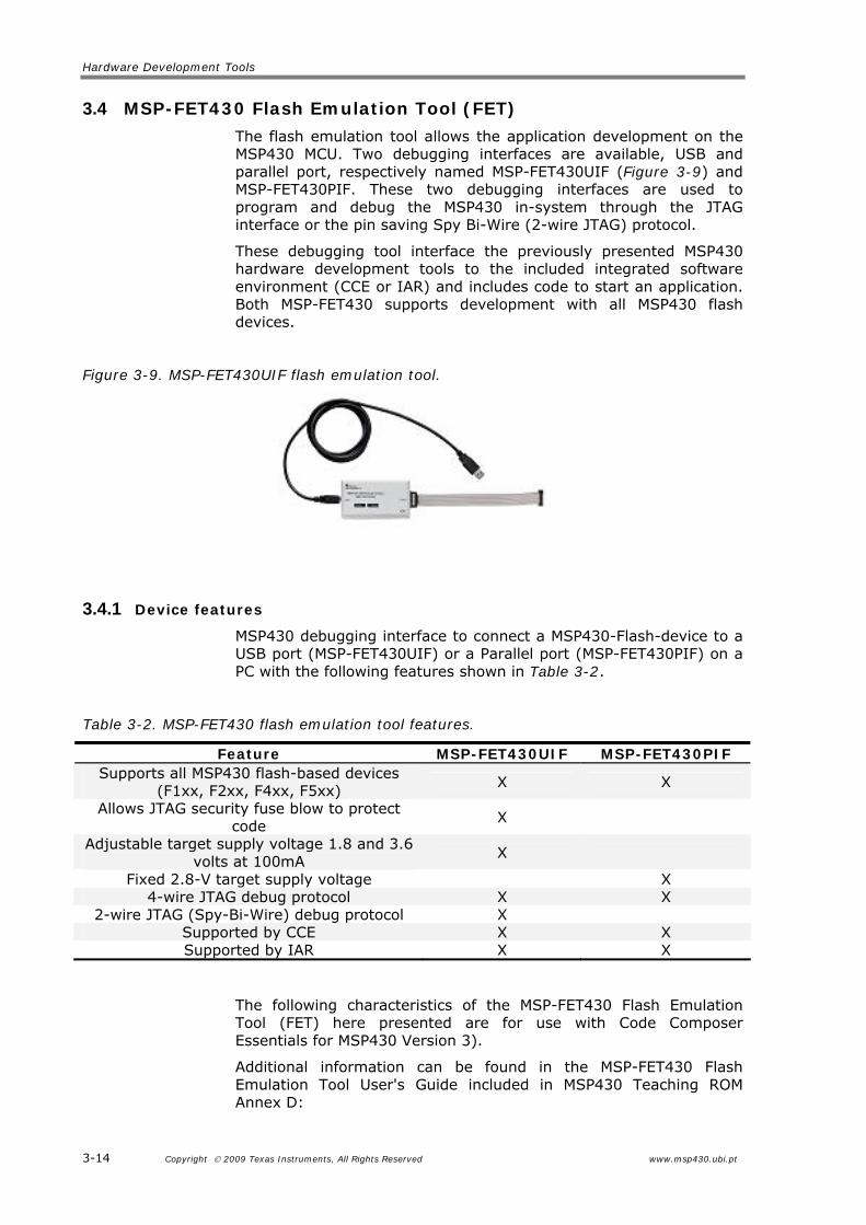
The flash emulation tool allows the application development on the MSP430 MCU. Two debugging interfaces are available, USB and parallel port, respectively named MSP-FET430UIF (Figure 3-9) and MSP-FET430PIF. These two debugging interfaces are used to program and debug the MSP430 in-system through the JTAG interface or the pin saving Spy Bi-Wire (2-wire JTAG) protocol.
These debugging tool interface the previously presented MSP430 hardware development tools to the included integrated software environment (CCE or IAR) and includes code to start an application. Both MSP-FET430 supports development with all MSP430 flash devices.
Figure 3-9. MSP-FET430UIF flash emulation tool.
3.4.1 Device features
MSP430 debugging interface to connect a MSP430-Flash-device to a USB port (MSP-FET430UIF) or a Parallel port (MSP-FET430PIF) on a PC with the following features shown in Table 3-2.
Feature MSP-FET430UIF MSP-FET430PIF Supports all MSP430 flash-based devices
(F1xx, F2xx, F4xx, F5xx) X X
Allows JTAG security fuse blow to protect code
X
Adjustable target supply voltage 1.8 and 3.6 volts at 100mA
X
Fixed 2.8-V target supply voltage X 4-wire JTAG debug protocol X X
2-wire JTAG (Spy-Bi-Wire) debug protocol X Supported by CCE X X Supported by IAR X X
The following characteristics of the MSP-FET430 Flash Emulation Tool (FET) here presented are for use with Code Composer Essentials for MSP430 Version 3).
Additional information can be found in the MSP-FET430 Flash Emulation Tool User's Guide included in MSP430 Teaching ROM Annex D:
MSP-FET430 Flash Emulation Tool (FET)
www.msp430.ubi.pt Copyright 2009 Texas Instruments, All Rights Reserved 3-15
MSP-FET430 Flash Emulation Tool (FET) (for use with Code Composer Essentials for MSP430 Version 3) User's Guide <slau157g.pdf>;
MSP-FET430 Flash Emulation Tool (FET) (for use with IAR Embedded Workbench Version 3+) User's Guide <slau138.k.pdf>.
3.4.2 Hardware Installation
Use the USB cable (MSP-FET430UIF) or the 25-conductor cable (MSP-FET430PIF) to connect the FET interface module to a USB port or to the parallel port of the PC. The necessary driver for accessing the ports (USB or parallel) is installed automatically during CCE installation.
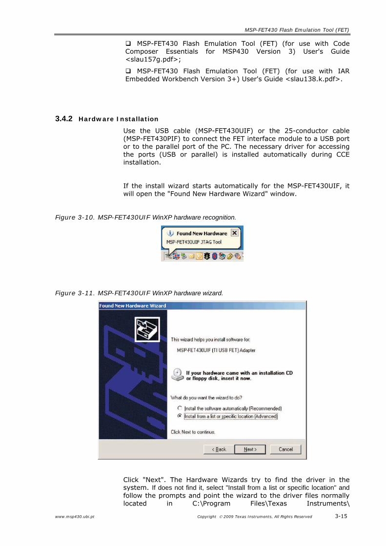
If the install wizard starts automatically for the MSP-FET430UIF, it will open the "Found New Hardware Wizard" window.
Click "Next". The Hardware Wizards try to find the driver in the system. If does not find it, select "Install from a list or specific location" and follow the prompts and point the wizard to the driver files normally located in C:\Program Files\Texas Instruments\
Hardware Development Tools
3-16 Copyright 2009 Texas Instruments, All Rights Reserved www.msp430.ubi.pt
MSP430_USB_DRIVERS_v3\ (this is the default location unless another installation directory was specified during CCE installation).
During installation, Windows may show a warning that the driver is not certified by Microsoft. Ignore this warning and click "Continue Anyway".
The wizard installs the driver files and it will show a message when has finished the installation of the software for "MSP-FET430UIF (TI USB FET) Adapter" (or "MSP430 Application UART").
After closing the hardware wizard, Windows automatically recognizes another new hardware device called "MSP-FET430UIF - Serial Port". Follow the same steps.
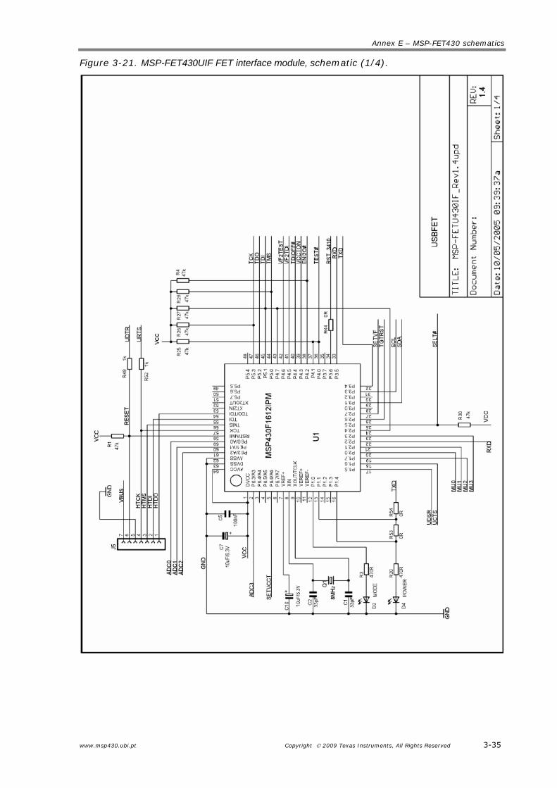
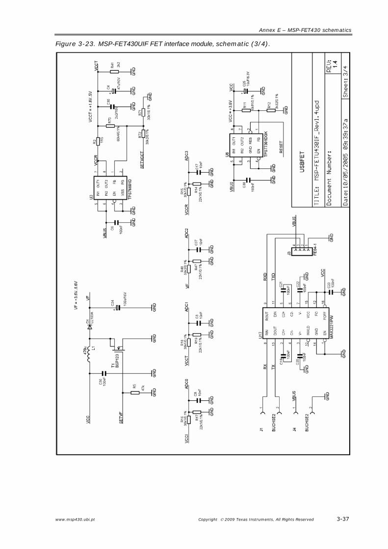
In Annex E are exposed the schematics of the MSP-FET430UIF and MSP-FET430PIF.
Experimenter’s boards support the TI’s wireless evaluation modules header: CCxxxxEMK boards. The transceiver modules are connected to the USART of the MSP430FG4618 and of the MSP430F5438 configured in SPI mode.
The CC2420EMK supports the 802.15.4/Zigbee standard;
The CC1100EMK may be configured to work at an RF carrier frequency of up to 868 MHz;
www.msp430.ubi.pt Copyright 2009 Texas Instruments, All Rights Reserved 3-17
The CC2500EMK/CC2420EMK at an RF carrier frequency of 2.4 GHz.
CC1100EMK Evaluation Module 868 MHz
The evaluation kit in combination with a CC1100 development kit.
This evaluation kit includes CC1100EM 868 MHz modules and antenna. The CC1100EMs are add-on daughter boards that require a CC1100-1150DK development kit for evaluation and development.
It allows performing RF measurements. Using SmartRF® Studio, the radio ICs can be configured with parameters that suit the intended application and easily measure sensitivity, output power and other RF parameters.
The smartRF®04DK includes a Silicon Labs 8051 core MCU with 16 kB of program memory and 1 kB of data memory. By programming this MCU and utilizing the various peripherals included on the Evaluation Board, the prototype of the intended application can be developed. All signals are brought out on 0.1" pin-row connectors so easy connection of other required circuitry is possible. These connectors are also compatible with Agilent logic analyser probes for easy debugging. It is also possible to disconnect the Silicon Labs MCU from the EVM board, and connect a MCU selected by the user to the I/O connectors.
CC2420EMK Evaluation Module IEEE 802.15.4/Zigbee
The CC2420 is a true single-chip 2.4 GHz 802.15.4 compliant RF transceiver designed for low-power and low-voltage wireless applications. The CC2420EMK evaluation kit in combination with a CC2420 development kit is a powerful and flexible tool specifically designed to evaluate the RF performance of the CC2420 and to minimize the time spent on evaluation.
This evaluation kit includes two CC2420EM modules and antennas. The CC2420EM are add-on daughter boards that require a CC2420DK or CC2420DBK development kit for evaluation and development.
CC2500EMK Evaluation Module 2.4 GHz
The CC2500EM evaluation modules are provided with antennas. These evaluation modules are add-on daughter boards that require a CC2500 development kit for evaluation and development.
It allows to do range testing (PER testing) and transfer data from one PC to another using the SmartRF®04DK, in order to evaluate how well the SmartRF®04 products fit the intended application.
It allows performing RF measurements. Using SmartRF® Studio, the radio ICs can be configured with parameters that suit the intended application and easily measure sensitivity, output power and other RF parameters.
Hardware Development Tools
3-18 Copyright 2009 Texas Instruments, All Rights Reserved www.msp430.ubi.pt
3.6 Third party hardware development tools
Texas Instrument’s Third-Party Network of several independent companies provides hardware development tools for TI’s line of MSP430 Ultra-Low Power Microcontroller products. The hardware tools provided by such companies concern Development Boards/Evaluation modules (EVMs), Production Programming Tools, Hardware Reference Design, Designer’s kits, and Adapters/Support Components.
There are several third party MSP430 hardware development tools. Their usage depends on the specific needs of the user, because different manufacturers provide different starter kits, benefiting the use of some peripherals at the detriment of others.
In a first approach, Softbaugh and Olimex provide a large quantity of the most general starter kits, providing feedback user interface, like LCD, LED, buttons and others. Additionally, Softbaugh provides RF boards (packet radio module for point-to-point and star networks, Zigbee stacks, among others).
In the following tables, it can be found the main features included in the boards of the hardware development tools provided by third party, divided into Communication, Human interface and Additional features, each one with specific characteristics. Consult the TI MSP430 Ultra-Low-Power Microcontrollers (MCU) internet page, on the Third-Party Network to check for changes or updates to the information posted concerning the Third-Party Hardware Tools (Development Boards/EVMs, Production Programming Tools, Hardware Reference Design, Designer’s kits, and Adapters/Support Components).
Hardware Development Tools
www.msp430.ubi.pt Copyright 2009 Texas Instruments, All Rights Reserved 3-19
Table 3-3. Communication interfaces included at Third-party hardware development tools.
Third party Board ref. MCU Ethernet USB SPI Port RS232 RS485 Wireless IrDA BSL
Elprotronic Inc. MSP430F169 Evaluation Board F169 X X X X Trainer KIT ET-MSP430 X (MODBUS) X (MODBUS) X (ISM band) Gill Instruments TCX-MSP430 CS8900A 10Base X MS-3002 X MS-3003 X MS-3004 F449 X MS-3005 F437 56K modem X
Microtrend Systems Inc.
MS-3006 F449 X
MSP430-169LCD F169 MSP430-4619LCD FG4619 X MSP430-1121STK2 F1121A X MSP430-169STK F169 X X MSP430-413STK2 F413 X MSP430-417STK2 F417 X MSP430-449STK2 F449 X MSP430-EasyWeb2 F149 CS8900 LAN controller+LAN transformer+RJ45 LAN connector X
Olimex, Ltd
MSP430-EasyWeb3 F149 CS8900 LAN controller+LAN transformer+RJ45 LAN connector MAX3232
PW-SB169 F169 PassWorld Y.K. PW-SB1611 F1611
ES449 F449 X ESG439 FG439 ES437 F437 ESW427 FW427 X ES427 F427 X ES417 F417 X ES169 F169 X ES1611 F1611 X ES1232 F1232 X DG439V FG439 X D437V F437 X DE427 FE427 X
3-20 Copyright 2009 Texas Instruments, All Rights Reserved www.msp430.ubi.pt
Table 3-4. Human interfaces included at Third-party hardware development tools. Third party Board ref. MCU Dallas LCD buttons buzzer Joystick LED Switch Microphone Headphone Pin Access
Elprotronic Inc. MSP430F169 Evaluation Board F169 2 2 all
Trainer KIT ET-MSP430 16x2 4 3 1 Gill Instruments
TCX-MSP430 16x2 4 4
MS-3002 X
MS-3003 X
MS-3004 F449 VI-322 2 all
MS-3005 F437
Microtrend Systems Inc.
MS-3006 F449 VI-322 all
MSP430-169LCD F169 NOKIA 3310 LCD 84x48 X 2 1 (reset) all
MSP430-4619LCD FG4619 NOKIA 6610 LCD 128x128 2 X all
MSP430-1121STK2 F1121A X 2+1(reset) X 2 all
MSP430-169STK F169 X LCD 16x2 3 2 1 1 all
MSP430-413STK2 F413 X 5 digits, 5 decimal counters, special signs 2 X 1 all
MSP430-417STK2 F417 X 5 digits, 5 decimal counters, special signs 2 X 1 all
MSP430-449STK2 F449 X X 4 X 1 all
MSP430-EasyWeb2 F149 iButton 16x2 X 4 4
Olimex, Ltd
MSP430-EasyWeb3 F149 3 all
PW-SB169 F169 101x64 X all PassWorld Y.K. PW-SB1611 F1611 101x64 X all
ES449 F449 7 digit 3v 4-mux SBLCDA2 2 4 all
ESG439 FG439 SBLCDA4 LCD 2 4 all
ES437 F437 SBLCDA4 LCD 2 4 all
ESW427 FW427 SBLCDA4 LCD 2 4 all
ES427 F427 SBLCDA4 LCD 2 4 all
ES417 F417 SBLCDA4 LCD 2 all
ES169 F169 2 all
ES1611 F1611 2 all
ES1232 F1232 2 all
DG439V FG439 3-1/2 digit LCD 1 3 all
D437V F437 3-1/2 digit LCD 1 3 all
DE427 FE427 SBLCDA4 LCD 2 2
SoftBaugh
DIr169 F169 2 2 X X all
CM2131 F2131 4
CM1611 F1611 4
CM1232 F1232 4
CM427 F427 4
CM417 F417 4
CM169 F169 4
Tecnotron
CM149 F149 4
Third party hardware development tools
www.msp430.ubi.pt Copyright 2009 Texas Instruments, All Rights Reserved 3-21
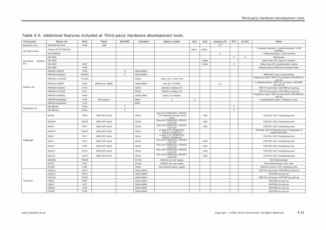
Table 3-5. Additional features included at Third-party hardware development tools. Third party Board ref. MCU Flash SD/MMC Oscillator battery holder ADC DAC Analog I/O RTC DC/DC Other
(c) Joystick, 4 LEDs, Prototyping space, headphone jack
(d) Accelerometer, 2 push buttons, 4 LEDs, Prototyping space
6. The MSP-EXP430F5438 demo board has:
(a) 3 timers and 2 SAR ADC;
(b) 2 timers and 2 SAR ADCs;
(c) 3 timers and 1 SAR ADC;
(d) 2 timers and 1 SAR ADC and 1 SD ADC.
FAQs
www.msp430.ubi.pt Copyright 2009 Texas Instruments, All Rights Reserved 3-23
3.8 FAQs
1. What devices can be programmed with the MSP-eZ430U debugging interface?
The MSP-eZ430U debugging interface was designed to communicate with devices over a Spy Bi-Wire interface. All members of the MSP430F20xx family of microcontrollers have been tested and are supported.
2. Does the eZ USB sticks support fuse blow?
Both MSP-eZ430U and eZ430-RF USB debugging interfaces lack the JTAG security fuse blow capability. To ensure firmware security on devices going to production, the USB Flash Emulation Tool or the Gang Programmer, which include the fuse blow feature are recommended.
3. What is the voltage supplied to the eZ target boards from the debugging interface?
Either the MSP-EZ430U or the eZ430-RF USB debugging interfaces supply a regulated 3.6 V to the MSP-eZ430D and to the eZ430-RF2500T target boards respectively.
4. Can other programming tools interface to the eZ target boards?
Both the MSP-EZ430D and the eZ430-RF2500T target boards will work with any programming tool supporting the 2-wire Spy Bi-Wire interface. Both the MSP430 USB FET (MSP-FET430UIF) and the Gang Programmer support these devices. See MSP-FET430 Flash Emulation Tool User’s Guide (SLAU138) for details on using MSP430 USB FET and the Gang Programmer for a 2-wire Spy-Bi-Wire interface.
5. What versions of IAR Embedded Workbench are supported by the eZ USB sticks?
Both the eZ430-F2013 and the eZ430-RF2500 hardware are supported by IAR Embedded Workbench KickStart Release 4.64 (IAR 3.42F) and Code Composer Essentials v2.03 (SP3) or higher. At the time of print, CCE is currently not supported by the SimpliciTI protocol or the Sensor Monitor Demo. Please check the TI web site for updates.
6. What are the part numbers for the connectors between the USB stick emulators and the target boards?
For the MSPeZ430U emulator and the MSP-eZ430D target board:
• Header: Mill-Max 850-10-004-20-001000
• Socket: Mill-Max 851-93-004-20-001000
For the eZ430-RF USB debugger and the eZ430-RF2500T target board:
• Header: Mill-Max 850-10-006-20-001000
• Socket: Mill-Max 851-93-006-20-001000
Hardware Development Tools
3-24 Copyright 2009 Texas Instruments, All Rights Reserved www.msp430.ubi.pt
Mill-Max: http://www.mill-max.com
7. Concerning the eZ430-RF2500 hardware tool, where to find more information about the 2.4-GHz chip antenna?
Part Number: 7488910245
Wϋrth Electronik Group: www.we-online.com
8. Why can't I get the debugger started?
(a) Check in the Device Manager for the COM Port assigned to the eZ430. If is detected a conflict with port already in use, the conflicting port may be disable or assign a new COM port to the device.
(b) Check all devices that use a serial port; even devices that do not show up in the Device Manager.
(c) Check if capacitors C6 or C9 are populated on the MSPeZ430U debugging interface, since they may have been unknowingly removed while opening the enclosure.
9. For the eZ430-RF2500 hardware tool, the MSP430 Application UART can’t be selected, the data isn’t received, or the demo application doesn’t appear to change.
(a) Ensure that the Application UART driver is correctly installed (run the installer for the Sensor Monitor Visualizer or newest version of the IAR KickStart or the CCE). Follows the instructions present in the hardware tool user guide < slau227c.pdf>.
To determine if the driver is correctly installed:
i) Plug in the eZ430-RF2500 USB debugging interface
ii) Right click My Computer and select Properties
iii) Select the Hardware tab and click on Device Manager
iv) Under Ports (COM & LPT) should be an entry for “MSP430 Application UART (COM xx)”.
If the entry is there, but no characters are received, restart the PC. If the Application UART is not listed, please re-install the driver following the instructions presented in the hardware tool user guide < slau227c.pdf>.
10. What is the RF range of the eZ430- RF2500?
Indoor line-of-sight range measured of more than 50 meters (practical range testing with one node connected to a PC and the other node connected to the battery board). This range can be significantly affected by the orientation of the boards and the environment. Please visit the TI website for additional reference designs and antenna options.
11. Why is my battery board different than in the documentation?
Since introduction, the eZ430RF-2500 battery board was slightly modified in order to reduce the wireless communications perturbation due to the relative position of the antenna to the batteries. The connections and function remain the same.
FAQs
www.msp430.ubi.pt Copyright 2009 Texas Instruments, All Rights Reserved 3-25
12. What devices can be programmed with the FG4618/F2013 experimenter’s board?
The experimenter’s board is designed to develop applications using the MSP430FG4618 and MSP430F2013. These devices can be replaced by MSP430FG461x and MSP430F20xx device derivatives, respectively.
13. How is power supplied to the FG4618/F2013 experimenter’s board?
Three supply options exist: 2xAAA battery power, JTAG and external power supplies are supported.
14. Can I use the Parallel FET (MSP-FET430PIF) to program/debug the MSP430?
The MSP4304618 supports the USB and Parallel Port FETs. The MSP430F2013 is supported by the USB FET (MSP-FET430UIF) only. The Parallel Port FET does not support the Spy Bi-Wire program/debug mode used.
15. I have erased and reprogrammed the MSP430; can I restore the factory programmed-firmware on the device(s)?
The software source files are available at the MSP-EXP430FG4618 documentation page at www.ti.com/msp430.
16. Why the MSP430FG4618 device is no longer accessible via JTAG after operation?
a) Verify that the target device is powered properly
b) If the target is powered locally, verify Vcc is applied to pin 4 of the JTAG header
c) If communication and power are correctly applied to the target and the issue persists, it may be due to the MSP430FG4618 accidentally being programmed with MSP430F2xx source code. In some conditions ‘F2xx source code loaded onto the ‘FG4618 can configure the SVS module to monitor SVSIN (P6.7) and reset the device in case of a low voltage condition externally applied. Temporarily connecting P6.7 of the ‘FG4618 to Vcc and reprogramming the target device with the valid source code will eliminate this issue.
17. Does the FG4618/F2013 experimenter’s board protect against blowing the JTAG fuse of the target devices?
No. Fuse blow capability is inherent to all Flash-based MSP430 devices in order to protect user’s intellectual property. Care must be taken to avoid the enabling of the fuse blow option during programming that would prevent further access to the MSP430 device(s) via JTAG.
18. I am measuring system current in the range of 30 mA, is this normal?
Hardware Development Tools
3-26 Copyright 2009 Texas Instruments, All Rights Reserved www.msp430.ubi.pt
Current consumption of the system is dependent on the functions and operation of the hardware being performed. The RF connectivity and isolated UART communication support, when used, can reach these current consumption levels. Take care that these elements are not accidentally enabled, specifically the isolated UART, if such system currents are not expected.
19. Can I use two FETs to perform simultaneous access of the FG4618 and F2013 during program/debug?
Yes, independent flash emulation tools (either USB or Parallel for ‘FG4618 and USB only for ‘F2013) can be simultaneously used to program the MSP430 target devices. When supplying power via the FET, it is recommended to use only one FET to source power. The second FET can sense this voltage level instead of supplying power, to avoid any voltage conflicts in-system. Additional details in the hardware tool user guide <slau213a.pdf>.
20. I have loaded the MSP430FG4618 and MSP430F2013 sample code for the capacitive touch sensing application. It doesn’t seem to be working, what is wrong?
Verify that the correct jumper settings are used for H1 enabling the I2C communication link between MSP430s. Make sure jumper JP2 is removed, disconnecting LED3 from the touchpad circuitry. When connected, the LED causes the measurement of the capacitive touch element on P1.0 to fail.
Annex A – eZ430-F2013 schematics
www.msp430.ubi.pt Copyright 2009 Texas Instruments, All Rights Reserved 3-27
Annex A – eZ430-F2013 schematics
Figure 3-13. eZ430-F2013 schematic.
Hardware Development Tools
3-28 Copyright 2009 Texas Instruments, All Rights Reserved www.msp430.ubi.pt
Annex B – eZ430-RF2500 schematics
Figure 3-14. eZ430-RF2500, USB Debugging Interface schematic.
Annex B – eZ430-RF2500 schematics
www.msp430.ubi.pt Copyright 2009 Texas Instruments, All Rights Reserved 3-29
Figure 3-15. eZ430-RF2500, USB Debugging Interface schematic.
Hardware Development Tools
3-30 Copyright 2009 Texas Instruments, All Rights Reserved www.msp430.ubi.pt
Figure 3-16. eZ430-RF2500, Target board and battery board schematic.