Grayhill Confidential Page 1 7/10/2014 3K Series Keypad Programmers Manual Grayhill PN: 3KUM1120-1 Revisions A Original Release 7/16/2009 B Corrected link in Sec. 5 referring to Sec 4.5.4 9/15/2009 C Clarified that some commands need to be sent from a Source Address of 249 (0xF9) 10/29/2009 D Corrected J1939 Name bitfield description, Sec 5.7 ECN 386038 10/26/2011 E Updated section 1.2, programmable features, to clarify configuration options. ECN 389166 RAL 10-8-2012 10/8/2012 G Added figure 2 showing 6 button keypad numbering. ECN #396686 RAL 7-10-2014 7/10/2014
Transcript
Grayhill Confidential Page 1 7/10/2014
3K Series Keypad
Programmers Manual
Grayhill PN: 3KUM1120-1
Revisions
A Original Release 7/16/2009
B Corrected link in Sec. 5 referring to Sec 4.5.4 9/15/2009
C Clarified that some commands need to be sent from a Source Address of 249 (0xF9)
10/29/2009
D Corrected J1939 Name bitfield description, Sec 5.7 ECN 386038
10/26/2011
E Updated section 1.2, programmable features, to clarify configuration options. ECN 389166 RAL 10-8-2012
This document describes the functionality and communication of the Grayhill 3K series CAN keypads. The functionality and communication protocol are independent of the number of keys and indicators that a given 3K series keypad version may have.
1.1. Reference Documents
The following documents are referenced within this document. 1. SAE-J1939 2. SAE-J1939/11 3. SAE-J1939/21 4. SAE-J1939/71 5. SAE-J1939/81
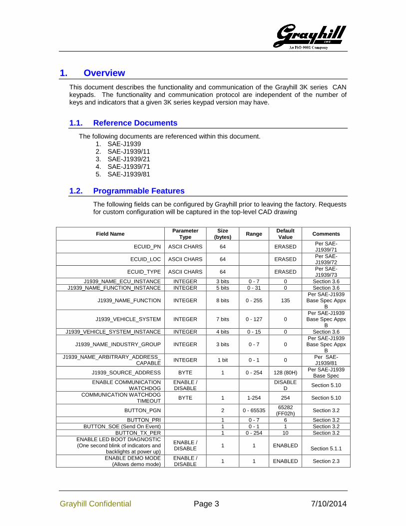
1.2. Programmable Features
The following fields can be configured by Grayhill prior to leaving the factory. Requests for custom configuration will be captured in the top-level CAD drawing
J1939_NAME_INDUSTRY_GROUP INTEGER 3 bits 0 - 7 0 Per SAE-J1939 Base Spec Appx
B
J1939_NAME_ARBITRARY_ADDRESS_CAPABLE
INTEGER 1 bit 0 - 1 0 Per SAE-J1939/81
J1939_SOURCE_ADDRESS BYTE 1 0 - 254 128 (80H) Per SAE-J1939
Base Spec
ENABLE COMMUNICATION WATCHDOG
ENABLE / DISABLE
DISABLE
D Section 5.10
COMMUNICATION WATCHDOG TIMEOUT
BYTE 1 1-254 254 Section 5.10
BUTTON_PGN 2 0 - 65535 65282
(FF02h) Section 3.2
BUTTON_PRI 1 0 - 7 6 Section 3.2
BUTTON_SOE (Send On Event) 1 0 - 1 1 Section 3.2
BUTTON_TX_PER 1 0 - 254 10 Section 3.2
ENABLE LED BOOT DIAGNOSTIC (One second blink of indicators and
backlights at power up)
ENABLE / DISABLE
1 1 ENABLED
Section 5.1.1
ENABLE DEMO MODE (Allows demo mode)
ENABLE / DISABLE
1 1 ENABLED Section 2.3
Grayhill Confidential Page 4 7/10/2014
2. Keypad Operation
An example of a Grayhill Standard keypad overlay is shown in Figure 1. Keys are numbered starting with 1 (1-20 shown). There are typically 3 indicators per key. The six button keypad numbering is structured as if the last row of an eight key horizontal 3K is still present. This allows customer applications to reuse application code in six button versions of an existing eight button configuration. See figure 2.
Figure 1 – Typical Key and Indicator Numbering
Figure 2 – Six Button Key and Indicator Numbering
2.1. Power Up Sequence
Upon first power up, if the Indicator Power Up Diagnostics flag is set the keypad lights all of the indicators and backlights at full brightness for one second. This serves as a visual test that all of the indicators are functional. Afterwards the keypad sends out an Address Claimed message. If the keypad loses arbitration with another device having the same source address and a lower Name value, it will either send another Address Claimed
Grayhill Confidential Page 5 7/10/2014
message with a new source address if the keypad is using Dynamic Addressing otherwise it will send out the Cannot Claim Address message. If the keypad is using Dynamic Addressing and cannot find an unused source address it will then send the Cannot Claim Address message. If a keypad sends out the Cannot Claim Address message it will not enter Run Mode (it will not transmit or act upon any messages).
2.2. Run Mode
In Run Mode, the keypad constantly monitors for Configuration and Control Messages and takes action accordingly.
Key information is sent according to its configuration which is either upon a key press, a periodic timer, or both. When a key is pressed the corresponding bit location in the data field is set.
LEDs are manipulated according to their configuration (blinking, on, off). The keypad constantly monitors for Configuration and Control Messages and takes action accordingly.
2.3. Demo Mode
Demo mode is entered by pressing and holding the 3rd
and 4th buttons while the keypad
initially receives power. It’s important to note that the buttons are referenced from the top, left corner and not necessarily the number on the button legends. When demo mode is entered the indicators will blink twice in about a one second time period. This will happen regardless if the Power Up Diagnostics is enabled or not. Anytime a button is pressed the corresponding indicator LED’s will change. Pressing it once will light the left. Pressing it again will light the left and center. A third time lights all three. A fourth time will turn them off. Additional presses will repeat the cycle.
Buttons one through six also control the indicator and backlight brightness intensity according to the table below.
5th button Both indicator and backlights full brightness
6th button Both indicator and backlights at dimmest level
In demo mode the keypad is still fully functional. To exit demo mode simply cycle power without pressing the 3
rd and 4
th buttons.
3. Keypad Configuration
The standard keypads have the capability to store configurations in non-volatile memory that control the keypad or provide user information about the keypad.
3.1. Source Address
The source address of the keypad can be changed in one of two ways:
1. Using the Commanded Address as explained in SAE-J1939/81. When this is done the keypad will broadcast a new Address Claim message with the new address. If arbitration is lost the keypad will revert back to the original address.
Grayhill Confidential Page 6 7/10/2014
2. Using the Change Source Address command as described in the Configuration and Control section. The new source address will take effect immediately and will not cause the unit to broadcast an Address Claim message.
3.2. Button Message Parameters
3.2.1. Button PGN
This parameter holds the 16 bit PGN value of the button message. The default value is 65282 (FF02h).
3.2.2. Button Priority
This parameter controls the priority field in the message ID. Valid values range from 0 to 7. The default value is 6.
3.2.3. Transmission Period
This parameter controls the transmission rate of the button message. When enabled, the period can be set in the range of 10ms to 2.54 seconds with a resolution of 10ms. When disabled (parameter value equals zero) the message is only sent upon button activity. The default value is 100ms.
3.2.4. Transmit Upon Change
This controls if an updated message is sent immediately regardless of if the send timer has expired or if it must wait until the timer has expired. This is automatically enabled if the Transmission Period is set to zero. The default is to transmit upon button change.
3.3. Indicator Parameters
3.3.1. Timeout Period
The indicators have a Timeout parameter that, when the timer expires, blinks all of the indicators at a fast rate letting the operator know that LED messages were not received within the timeout period. When enabled, the timeout period can range between 100ms to 25.4 seconds. The timeout period is disabled by default. This parameter must be sent from a Source Address of 249 (0xF9).
3.3.2. Power Up Diagnostics
When enabled, all of the indicators and backlights will turn on for approximately one second. The keypad will then operate normally. Disabling this feature enables the keypad to begin normal operation quicker. This parameter is enabled by default. This parameter must be sent from a Source Address of 249 (0xF9).
3.4. Proprietary ID
The Proprietary ID is programmed into the keypad at the factory and provides the ability for the customer to only allow approved keypads to operate in the customer’s system. The Proprietary ID uses a PGN of 65408 (FF80h) with a data length of eight bytes. When not used all eight data bytes will be 255 (FFh).
Grayhill Confidential Page 7 7/10/2014
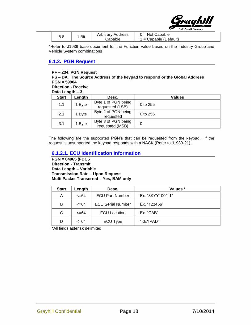
3.5. J1939 ECUID
The ECUID information can be read using a BAM transfer when requesting PGN 64965 (FDC5h). The ECUID consists of four fields:
o ECU Part Number o ECU Serial Number o ECU Location o ECU Type
The ECU serial number is the same as the Identity Number in the Address Claimed NAME field. Refer to Sec. 5.7 to change the ID field.
The remaining three fields can each store up to 64 ASCII characters and are programmed using the commands in Configuration and Control Commands ECUID Command and ECUID Field Data.
Changing the ECUID fields must be done with a device having a source address of 249 (F9h).
3.6. J1939 NAME Fields
All of the fields with the exception of the Manufacturer Code can be modified using the Changing J1939 NAME Fields. Changing the NAME fields must be done with a device having a source address of 249 (F9h).
4. Communications
4.1. Message Header Description
Figure 2 illustrates the format of the CAN message ID. A brief description of each field follows.
Figure 2
4.1.1. Priority
This 3-bit field is used to define the priority during arbitration. ‘000’ is the highest priority and is usually associated with high-speed control messages. Low priority is used for non-critical configuration and information messages.
4.1.2. DP (Data Page)
This 1-bit field defines on which data page (0 or 1) the message is defined in the J1939 specification. Page 0 contains the messages that are presently defined, while Page 1 is for future expansion according to J1939.
Grayhill Confidential Page 8 7/10/2014
4.1.3. Protocol Data Unit (PDU) - PDU Format (PF)
This 8-bit field determines the format of the message and is one of the fields that determine the Parameter Group Number of the message (see 4.1.6). If the value is between 0 and 239, the message is a PDU 1 Format message. These messages are sent to specific addresses.
4.1.4. Protocol Data Unit (PDU) - PDU Specific (PS)
The PDU Specific (PS) field is the Destination Address (DA). If the value is between 240 and 255, the message is a PDU 2 Format message. These messages are not sent to a specific address, but are instead broadcast to the entire network. The PS then becomes the Group Extension (GE) field.
4.1.5. Source Address
This 8-bit field is the source address of the device that sent the message.
4.1.6. Parameter Group Number
J1939 defines allowable messages by their Parameter Group Number (PGN). The Parameter Group Number is a 3-byte value that uniquely defines the message purpose. A PGN has the following format: If the PDU Format value for a message is less than 240, then the last 8 bits of the PGN are set to ‘0’. The specification gives the decimal equivalent of the PGNs. To obtain the PF and PS values to use for a specific message, convert the decimal value from the specification to hexadecimal and use the last two bytes. These values can then be used to either send messages on the network or to request messages from other source addresses.
4.2. Bitfield Location and Byte Ordering
The byte and bit ordering and location within the data field are per the J1939 specification. The first data byte is sent first and is referenced as Byte 1. The LSB of the data bytes are on the right and are referenced as Bit 1.
The convention used to locate a parameter in the data field is the same as specified in SAE-J1939/71. The format used is “R.x” where R is the byte number and x is the starting bit number within the byte. The length is the number of bits starting at this point.
Example 1: Location 4.3 with a length of 3 bits would have the value of 1 as illustrated below.
Byte 4 = 0x67 = 0b01100111. The bold value is the three bit field holding a value of 0b001.
Example 2: Location 4.3 with a length of 3 bits would have the value of 6 as illustrated below.
Byte 4 = 0x7b = 0b01111011. The bold value is the three bit field holding a value of 0b110.
4.3. Keypad Source Address
The source address of the Grayhill standard keypad is set to 128 (80h) at the factory. This may be modified either dynamically if Dynamic Addressing is turned on, with the Commanded Address message in accordance with J1939-81, or with the proprietary Source Address Command . The source address value is stored in non-volatile memory.
Grayhill Confidential Page 9 7/10/2014
The ability to change the source address will allow multiple keypads to coexist in the same system.
4.4. Physical Layer
The bit rate is 250kbps per J1939/11. The connector is a 4 pin Deutsch equivalent with the following pin out:
1. Power 2. Ground 3. CAN_H 4. CAN_L
4.5. Standard Messages
The Key Press Data PGN uses the Proprietary B PDU2 format (PF = 255) that broadcasts to no specific address the status of the keys, and the Control Data PGN uses Proprietary A PDU1 format (PF = 239).
The indicators can be controlled in one of two ways. The first is by using the Auxiliary I/O #2 and #3 PGNs where each two bit field within the 64 bit data bits controls a corresponding indicator. The second is using the Proprietary A PGN where the indicators are in banks with respect to the associated button and addressed in the same way.
4.5.1. Key Press Data PGN
PGN – 65282 (FF02h), Proprietary B PDU2 Format
Direction - Transmit
Priority – 6
Data Length - 8
Transmission Rate – 100ms (programmable)
*The Key Press PGN number can be reassigned using a configuration command.
Start Length Desc. Values
1.1 2 bits Key 1
0b00-Key Not Pressed 0b01-Key Pressed 0b10-Error 0b11-Unused Key
1.3 2 bits Key 2 Same
1.5 2 bits Key 3 Same
1.7 2 bits Key 4 Same
2.1 2 bits Key 5 Same
2.3 2 bits Key 6 Same
2.5 2 bits Key 7 Same
2.7 2 bits Key 8 Same
3.1 2 bits Key 9 Same
3.3 2 bits Key 10 Same
3.5 2 bits Key 11 Same
3.7 2 bits Key 12 Same
4.1 2 bits Key 13 Same
4.3 2 bits Key 14 Same
4.5 2 bits Key 15 Same
4.7 2 bits Key 16 Same
Grayhill Confidential Page 10 7/10/2014
5.1 2 bits Key 17 Same
5.3 2 bits Key 18 Same
5.5 2 bits Key 19 Same
5.7 2 bits Key 20 Same
6.1 2 bits Key 21 Same
6.3 2 bits Key 22 Same
6.5 2 bits Key 23 Same
6.7 2 bits Key 24 Same
7.1 2 bits Key 25 Same
7.3 2 bits Key 26 Same
7.5 2 bits Key 27 Same
7.7 2 bits Key 28 Same
8.1 2 bits Key 29 Same
8.3 2 bits Key 30 Same
8.5 2 bits Key 31 Same
8.7 2 bits Key 32 Same
Example: Pressing key 12 will cause the following message to be transmitted. (Assume a 20 key device).
PS – DA, The Source Address of the keypad. Default value: 128 (80h)
PGN – 42752 (A700h), Auxilary I/O #2, PDU1 Format
Direction - Receive
Data Length – 8
Start Length Button LED Pos Values
1.1 2 bits 1 Left
0b00-Indicator Off 0b01-Indicator On 0b10-Indicator Blink Medium 0b11-No Change
1.3 2 bits 1 Center Same
1.5 2 bits 1 Right Same
1.7 2 bits 2 Left Same
2.1 2 bits 2 Center Same
2.3 2 bits 2 Right Same
2.5 2 bits 3 Left Same
2.7 2 bits 3 Center Same
3.1 2 bits 3 Right Same
3.3 2 bits 4 Left Same
3.5 2 bits 4 Center Same
Grayhill Confidential Page 11 7/10/2014
3.7 2 bits 4 Right Same
4.1 2 bits 5 Left Same
4.3 2 bits 5 Center Same
4.5 2 bits 5 Right Same
4.7 2 bits 6 Left Same
5.1 2 bits 6 Center Same
5.3 2 bits 6 Right Same
5.5 2 bits 7 Left Same
5.7 2 bits 7 Center Same
6.1 2 bits 7 Right Same
6.3 2 bits 8 Left Same
6.5 2 bits 8 Center Same
6.7 2 bits 8 Right Same
7.1 2 bits 9 Left Same
7.3 2 bits 9 Center Same
7.5 2 bits 9 Right Same
7.7 2 bits 10 Left Same
8.1 2 bits 10 Center Same
8.3 2 bits 10 Right Same
8.5 4 bits N/A N/A Unused
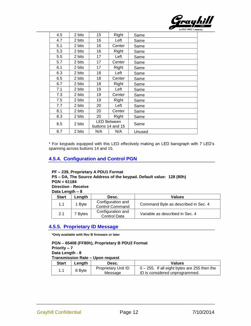
4.5.3. LED Indicator PGN #2
*Only available with Rev B firmware or later
PF – 166 (A6h)
PS – DA, The Source Address of the keypad. Default value: 128 (80h)
PGN – 42496 (A600h), Auxilary I/O #3, PDU1 Format
Direction - Receive
Data Length – 8
Start Length Button LED Pos Values
1.1 2 bits 11 Left
0b00-Indicator Off 0b01-Indicator On 0b10-Indicator Blink Medium 0b11-No Change
1.3 2 bits 11 Center Same
1.5 2 bits 11 Right Same
1.7 2 bits 12 Left Same
2.1 2 bits 12 Center Same
2.3 2 bits 12 Right Same
2.5 2 bits 13 Left Same
2.7 2 bits 13 Center Same
3.1 2 bits 13 Right Same
3.3 2 bits 14 Left Same
3.5 2 bits 14 Center Same
3.7 2 bits 14 Right Same
4.1 2 bits 15 Left Same
4.3 2 bits 15 Center Same
Grayhill Confidential Page 12 7/10/2014
4.5 2 bits 15 Right Same
4.7 2 bits 16 Left Same
5.1 2 bits 16 Center Same
5.3 2 bits 16 Right Same
5.5 2 bits 17 Left Same
5.7 2 bits 17 Center Same
6.1 2 bits 17 Right Same
6.3 2 bits 18 Left Same
6.5 2 bits 18 Center Same
6.7 2 bits 18 Right Same
7.1 2 bits 19 Left Same
7.3 2 bits 19 Center Same
7.5 2 bits 19 Right Same
7.7 2 bits 20 Left Same
8.1 2 bits 20 Center Same
8.3 2 bits 20 Right Same
8.5 2 bits LED Between
buttons 14 and 15 Same
8.7 2 bits N/A N/A Unused
* For keypads equipped with this LED effectively making an LED barograph with 7 LED’s spanning across buttons 14 and 15.
4.5.4. Configuration and Control PGN
PF – 239, Proprietary A PDU1 Format
PS – DA, The Source Address of the keypad. Default value: 128 (80h)
PGN = 61184
Direction - Receive
Data Length – 8
Start Length Desc. Values
1.1 1 Byte Configuration and Control Command
Command Byte as described in Sec. 4
2.1 7 Bytes Configuration and
Control Data Variable as described in Sec. 4
4.5.5. Proprietary ID Message
*Only available with Rev B firmware or later
PGN – 65408 (FF80h), Proprietary B PDU2 Format
Priority – 7
Data Length - 8
Transmission Rate – Upon request
Start Length Desc. Values
1.1 8 Byte Proprietary Unit ID
Message 0 – 255. If all eight bytes are 255 then the ID is considered unprogrammed.
Grayhill Confidential Page 13 7/10/2014
5. Configuration and Control Commands
Changing the configuration and how the keypad behaves is done with the Configuration and Control message described in Sec 4.5.4. The first byte serves as the command byte. Where applicable, changes take effect immediately and are stored in non-volatile memory unless otherwise noted. Note that some commands will only take effect if sent from a source address of 249 (F9h).
5.1. Indicator Data 1-32 (01h-20h)
This is an alternative to using the LED Indicator PGN’s 1 and 2 that allows three different blink rates.
Data field
Start Length Desc. Value
1.1 8 bits Indicator Bank 01h to 20h (Corresponding to the Key number 1 to 32).
2.1 4 bits Left Most
Indicator in the Bank
0b0000-Off 0b0001-On 0b0010 - Blink Slow (approx. 1/2 Hertz) 0b0011 - Blink Med. (approx. 1 Hertz) 0b0100 - Blink Fast (approx 2 Hertz) 0b1111 – Not Available
2.4 4 bits Center Indicator Same
3.1 4 bits Right Indicator Same
Not stored in nonvolatile memory.
Example: Sending the following message to a keypad having the default address of 0x80 will leave the center indicator unchanged while turning off the left indicator and fast blink the right indicator of button three.
Example: Sending the following message to a keypad having an address of 0x85 will set the indicator brightness to 50% while leaving the backlight brightness alone.
dd – The value multiplied by 10ms. Valid range: 1..255 yielding between 10ms to 2.54 seconds. A value of zero automatically assumes transmit upon event.
Event – Valid settings is 0 or 1. A value of one sends the key message upon change in key information. Upon transmission the timer is reset. A value of zero will cause the message to be transmitted at the specified time interval.
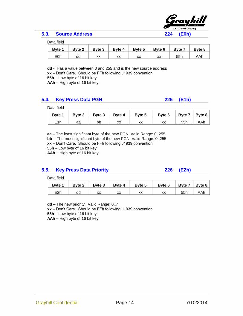
xx – Don’t Care. Should be FFh following J1939 convention
55h – Low byte of 16 bit key
AAh – High byte of 16 bit key
5.7. Changing J1939 NAME Fields 228 (E4h)
*Note: Must be sent from source address of 249 (0xF9)
dd – This holds the timeout value in units of 100ms that controls when and if all of the indicators will blink rapidly indicating CAN messages that control the indicators’ state have not been received within the timeout period. A value of zero disables this feature. A value of FFh results in no change.
Bytes 3 through 6 should be set to FFh for possible future expandability.
5.11. Indicator Diagnostics and Demo 232 (E8h)
*Only available with Rev B firmware or later
*Note: Must be sent from source address of 249 (0xF9)
DIAG – A non-zero value, with the exception of FFh, causes the keypad to blink all of the indicators and backlights on for about one second to serve as a visual tool that the keypad is powered up and the indicators are functioning properly. A value of zero bypasses this routine and, in turn, speeds up the bootup process. If the value is equal to FFh the command is ignored.
DEMO – A non-zero value, with the exception of FFh, causes the keypad to have the ability to enter demo mode. Demo mode will be entered if the 3
rd and 4
th buttons are pressed
during power up. All of the indicators will blink twice and demo mode entered regardless of the DIAG setting. If the value is equal to FFh the command is ignored.
Bytes 4 through 6 should be set to FFh for possible future expandability.
6. Other J1939 Commands
The following messages are defined in the J1939 documents and are implemented in the keypad.
6.1.1. Address Claimed
PF – 238, Address Claimed
PS – 255, The destination address should always be the Global Address
PGN = 60928
Direction – Transmit and receive
Data Length – 8
Priority - 6
Transmission Rate – Upon boot or whenever requested
Start Length Desc. Values
1.1 21 Bits Identity Number 0 to 221
-1
3.6 11 Bits Manufacturers Code 294 (Assigned to Grayhill by SAE)
*Refer to J1939 base document for the Function value based on the Industry Group and Vehicle System combinations
6.1.2. PGN Request
PF – 234, PGN Request
PS – DA, The Source Address of the keypad to respond or the Global Address
PGN = 59904
Direction - Receive
Data Length – 3
Start Length Desc. Values
1.1 1 Byte Byte 1 of PGN being
requested (LSB) 0 to 255
2.1 1 Byte Byte 2 of PGN being
requested 0 to 255
3.1 1 Byte Byte 3 of PGN being
requested (MSB) 0
The following are the supported PGN’s that can be requested from the keypad. If the request is unsupported the keypad responds with a NACK (Refer to J1939-21).
6.1.2.1. ECU Identification Information PGN = 64965 (FDC5