39
The risks of marine transportation of LNG Aker Arctic and LNG-fuelled ships Maritime responsible choises for the Baltic Sea July 26, 2012 Mauri Lindholm Aker Arctic Technology Inc
The risks of marine transportation of LNG
Aker Arctic
and LNG -fuelled ships
Maritime responsible choises for the Baltic Sea
July 26, 2012 Mauri LindholmAker Arctic Technology Inc
Aker ArcticGeneral - about LNG as marine fuel
� In the near future we’ll see the first LNG-fuelled ships in the Finnish waters and elsewhere in the Baltic Sea
� As soon as the necessary LNG infrastructure develops and is built up it is evident that the especially the short sea shipping sector will go more for gas-fuelled ships
© 2012 Aker Arctic Technology Inc
The Ice Technology PartnerSlide 2
� Good examples are found in Norway
� Ship operators, authorities and rescue organisations need to be aware of the basics of LNG fuel, it’s safe handling and related safety precautions

Aker ArcticCONTENTS
� What is LNG?� LNG as fuel� Why LNG?� Challenges of LNG as fuel� LNG-fuelled ships – something new?� LNG ship and tank types� LNG-fuelled ships of today
© 2012 Aker Arctic Technology Inc
The Ice Technology PartnerSlide 3
� LNG-fuelled ships of today� Future ship types suited for LNG fuel� Status of related rules and regulations� Current safety satndards� Scope of IGF Code� Main design issues� Machinery space configurations
Conclusions
Aker ArcticWhat is LNG
� Natural gas in liquefied form at about -160°C, cryogenic temperature
� Densified gas, liquid takes 1/600 of the volume of gaseous form
� Main component is methane CH4
� Colourless, odourless, non-toxic, non-corrosive gas
� Gaseous methane is lighter than air
� About 20% more energy per mass unit than Heavy Fuel Oil
© 2012 Aker Arctic Technology Inc
The Ice Technology PartnerSlide 4
� About 20% more energy per mass unit than Heavy Fuel Oil
� Lightweight liquid, density 0.42 to 0.45 t/m3 ⇒ storing takes much more volume than other fuels
� Flammable, but high self ignition temperature high: 595ºC
� Flammable only in between 5% - 15% mixture with air
Aker ArcticLNG as fuel- in comparison to fuel oils
� Burned in lean mixture in combustion engines � Low combustion temperature
⇒ 80-90% reduction in NOx emissions� Contains no sulphur
⇒ 100% reduction in SOx emissions� Simplest hydrocarbon with little carbon and much hydrogen
© 2012 Aker Arctic Technology Inc
The Ice Technology PartnerSlide 5
� Simplest hydrocarbon with little carbon and much hydrogen⇒ 25-30% reduction in CO2 compared with oil
� Clean combustion, no visible smoke or soot� Low maintenance of engines� High heat value: 50 to 55 MJ/kg (Medium Diesel Oil 43 MJ/kg)
Aker ArcticWhy to go for LNG fuel
� Environmental aspects: cleaner fuel, lower emissions
� Availability and distribution of LNG is improving
� LNG offers low fuel costs, potentially lower than heavy fuel oil
� World gas resources are vast, larger than those of oil
© 2012 Aker Arctic Technology Inc
The Ice Technology PartnerSlide 6
� Annual increase of LNG production growing 7 to 8%
� Proven technology: Wide scale transportation, handling and utilisation since early 70’s
� Newest codes provide guidance and safety measures for ships using gas as fuel
Aker ArcticWhy to go for LNG fuel(continued)
� More stringent emission limitations for shipping industry, IMO’s new requirements coming into force gradually
� Introduction of Emission Control Areas� Requirements of environmentally efficient ship desigs
(EEDI)
© 2012 Aker Arctic Technology Inc
The Ice Technology PartnerSlide 7
(EEDI)� Fullfilling of most stringent emission requirements
without any additional purification of exhaust gases� Proven storage and handling technology are available� Proven gas engines are available, dual fuel engines can
burn either oil or gas with immediate change-over� High thermal efficiency, low maintenance of engines
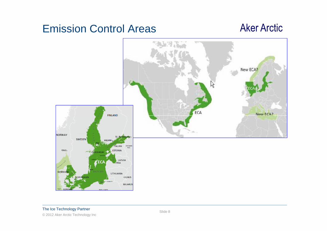
Aker ArcticEmission Control Areas
© 2012 Aker Arctic Technology Inc
The Ice Technology PartnerSlide 8
Aker ArcticMedium speed gas engines
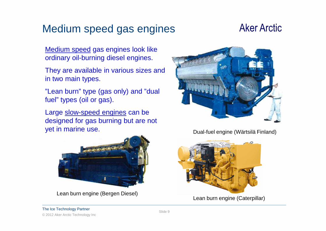
Medium speed gas engines look like ordinary oil-burning diesel engines.
They are available in various sizes and in two main types.
”Lean burn” type (gas only) and ”dual fuel” types (oil or gas).
Large slow-speed engines can be
© 2012 Aker Arctic Technology Inc
The Ice Technology PartnerSlide 9
Large slow-speed engines can be designed for gas burning but are not yet in marine use. Dual-fuel engine (Wärtsilä Finland)
Lean burn engine (Bergen Diesel)Lean burn engine (Caterpillar)
Aker ArcticChallenges of LNG as fuel
� Methane is a fossile, not renewable fuel
� Methane is one of the ’greenhouse effect gases’
– release of methane should be minimized to nil in all phases from LNG production to transportation, storing and burning
� Handling and storing of flammable cryogenic fuel
© 2012 Aker Arctic Technology Inc
The Ice Technology PartnerSlide 10
� Handling and storing of flammable cryogenic fuel requires dedicated materials, equipment and procedures
� Dual-fuel engines let very small amounts of methane gas through into exhaust gas - ’methane slip’
Aker ArcticLNG-fuelled ships – something new?
� Large LNG carriers have been built and operated for more than 40 years, the number of existing fleet is growing and exceeds 300 ships
� With only a few exceptions all LNG tankers are using gas as secondary or primary fuel
- so-called natural boil-off of cargo is utilised as part fuel, the rest can be vaporised from LNG or fuel oil is
© 2012 Aker Arctic Technology Inc
The Ice Technology PartnerSlide 11
fuel, the rest can be vaporised from LNG or fuel oil is used
- earlier all LNG carriers were with steam turbine machinery, today diesel-electric machinery with dual-fuel engines have taken over and is a more common choise in new ships
Aker ArcticLNG-fuelled ships – something new?(continued)
Alternative cargo tank concepts have been developed;
- prismatic membrane tanks and spherical tanks for larger ships
- pressure vessel type tanks for smaller ship applications
� International codes for technical solutions and safety
© 2012 Aker Arctic Technology Inc
The Ice Technology PartnerSlide 12
� International codes for technical solutions and safety are well established and well followed
� All phases of LNG handling is taken care by qualified personnel on land and onboard ships
� In general LNG ships and LNG storing and transportation have excellent safety record

Aker ArcticLNG carrier types
Membrane
© 2012 Aker Arctic Technology Inc
The Ice Technology PartnerSlide 13
Moss type tanks
Membrane type tanks
Pressure tank type
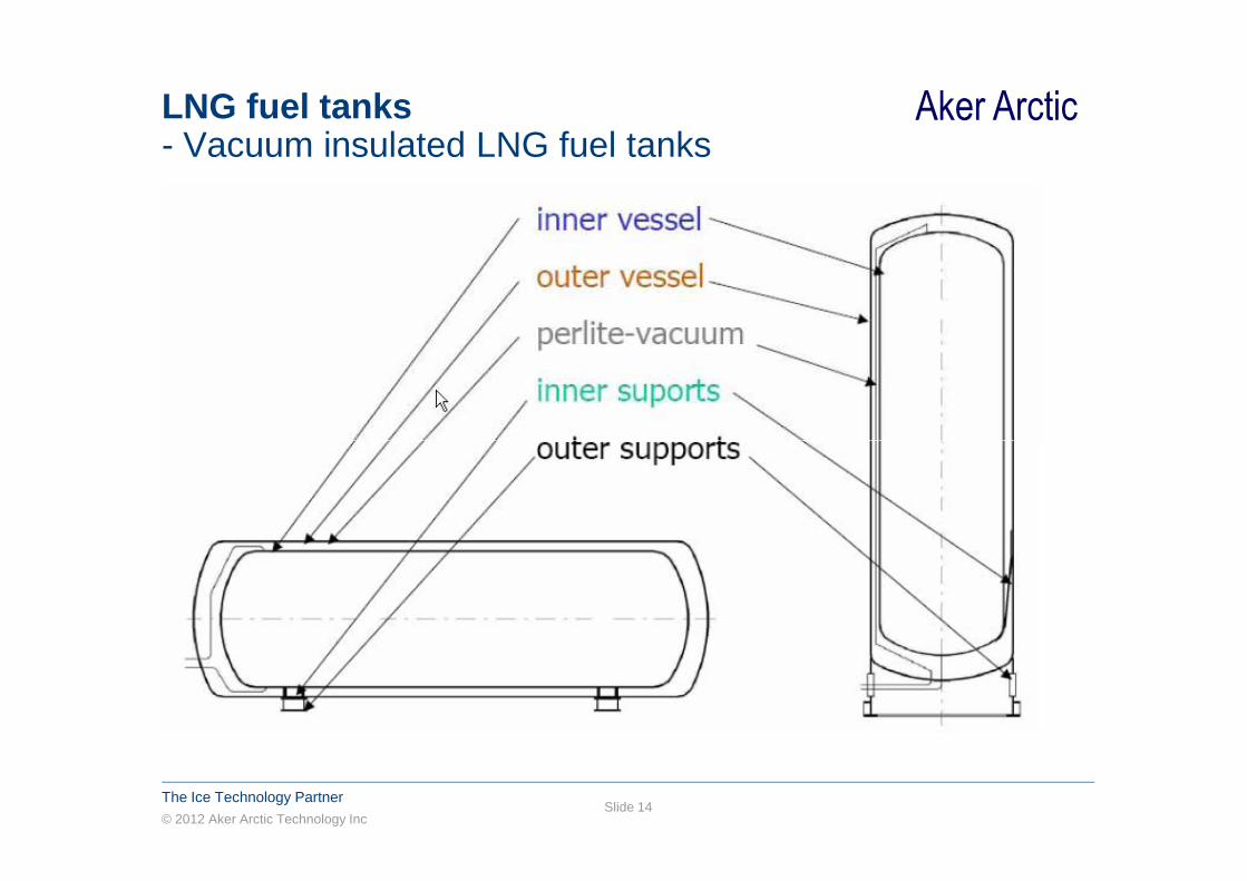
Aker ArcticLNG fuel tanks- Vacuum insulated LNG fuel tanks
© 2012 Aker Arctic Technology Inc
The Ice Technology PartnerSlide 14
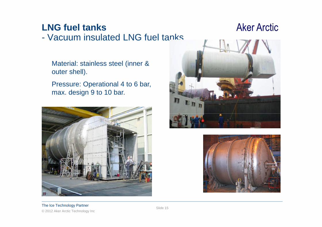
Aker ArcticLNG fuel tanks- Vacuum insulated LNG fuel tanks
Material: stainless steel (inner & outer shell).
Pressure: Operational 4 to 6 bar, max. design 9 to 10 bar.
© 2012 Aker Arctic Technology Inc
The Ice Technology PartnerSlide 15
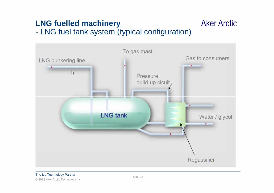
Aker ArcticLNG fuelled machinery- LNG fuel tank system (typical configuration)
© 2012 Aker Arctic Technology Inc
The Ice Technology PartnerSlide 16

Aker ArcticLNG fuelled ship of today
LNG carrying ships
© 2012 Aker Arctic Technology Inc
The Ice Technology PartnerSlide 17
LNG carrying ships
� The large LNG carriers transporting LNG from overseas production plants to worlwide market (hundreds of ships)
� Smaller LNG feeders taking care of local distribution of LNG (tens of ships)
� LNG bunker ships (only a few existing)
Aker ArcticLNG fuelled ship of today(continued)
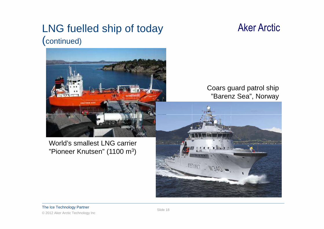
Coars guard patrol ship ”Barenz Sea”, Norway
© 2012 Aker Arctic Technology Inc
The Ice Technology PartnerSlide 18
World’s smallest LNG carrier ”Pioneer Knutsen” (1100 m3)

Aker ArcticLNG fuelled ship of today(continued)
World’s first gas-fuelled ferry ”Glutra”, Norway
© 2012 Aker Arctic Technology Inc
The Ice Technology PartnerSlide 19
Other LNG fuelled ships
� Car/passenger ferries (many in Norway)
� Offshore supply and service ships (many in Norway)
� Patrol and coast guard ships (some)
� Smaller cargo ships, tankers, river ships (some)
� Car/passenger cruise ship (under construction)
100 dwt chemical tanker ”Argonon”, Holland 2012
World’s first gas-fuelled ferry ”Glutra”, Norway

Aker ArcticLNG fuelled ship of today(continued)
”Pioneer Knutsen”
© 2012 Aker Arctic Technology Inc
The Ice Technology PartnerSlide 20
”Coral Methane”
”Pioneer Knutsen”
Aker ArcticLNG fuelled ship of today(continued)
LNG shipping industry has an excellent safety recor d
– No shipboard fatalities over the life of the indust ry associated with cargo
– No major losses of cargo and only one minor LNG onboard fire (lightning strike near vent riser, car go
© 2012 Aker Arctic Technology Inc
The Ice Technology PartnerSlide 21
onboard fire (lightning strike near vent riser, car go tanks not affected)
– Two groundings resulting in major hull breaches without cargo loss
Aker ArcticFuture ship types suited for LNG fuel� Any ship types� Modifications of existing ships machineries for LNG fuel� Short sea shipping sector most potential, with regular routes and
dense traffic� Small ferries, pilot boats, patrol boats� Small river and coastal tankers, dry cargo and tourist ships soon
ordered with gas fuel� Offshore supply and service ships, icebreakers and ice
© 2012 Aker Arctic Technology Inc
The Ice Technology PartnerSlide 22
� Offshore supply and service ships, icebreakers and ice management ships
� Plans for large cargo ships, container ships� Plans for large passenger ships� The first LNG-fuelled ships in Finland:
Large car-passenger ship ”Viking Grace” (early 2013)
Patrol and rescue vessel for the Finnish coast guard (2014)

Aker ArcticLNG-fuelled passenger ships
© 2012 Aker Arctic Technology Inc
The Ice Technology PartnerSlide 23
”Viking Grace” (2013)

Aker ArcticFuture ship types suited for LNG fuel
Icebreaking Platform Supply Vessel
© 2012 Aker Arctic Technology Inc
The Ice Technology PartnerSlide 24
LNG feederLNG bunkering ship

Aker Arctic
1 x 590 m3 LNG tank corresponding to
~ 1/3 of the required LNG fuel capacity!
ARC 105 PSV - LNG-fuelled version- general arrangement (with one gas fuel tank)
© 2012 Aker Arctic Technology Inc
The Ice Technology PartnerSlide 25
Aker Arctic
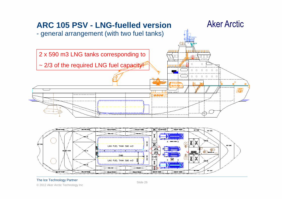
2 x 590 m3 LNG tanks corresponding to
~ 2/3 of the required LNG fuel capacity!
ARC 105 PSV - LNG-fuelled version- general arrangement (with two fuel tanks)
© 2012 Aker Arctic Technology Inc
The Ice Technology PartnerSlide 26

Aker ArcticStatus of related rules and regulationsGAS CARRIERS� IMO IGC (International Gas Code)- Intended for design and construction of gas carriers� SIGTTO & OCIMF industry standards- standardisation, cargo operations, mooring, ship-to-ship cargo transfer� Classification society rules since 2001
GAS-FUELLED SHIPS� Norwegian maritime directorate, National authorities� Class rules and guidelines (DNV, LR, GL, ABS)
© 2012 Aker Arctic Technology Inc
The Ice Technology PartnerSlide 27
� Class rules and guidelines (DNV, LR, GL, ABS)� IMO published Resolution MSC.285(86), Interim Guidelines on Safety for Natural Gas-Fuelled Engine Installations in Ships ⇒ IGF Code (2014)
BUNKERING AND PORT OPERATION OF LNG� Less experiece and documentation � Guidance by industrial parties and classification societies� ISO, Safety authorities, national rules
The International Maritime Organization (IMO) is in the process of developing anInternational Code on safety for ships using natura l gas and other low-flashpoint fuels.
Aker ArcticCurrent International Safety Standards- for gas-fuelled ships
In addition to the IMO Interim Guidelines, several classification societies have published rules or guides for gas-fueled ships.
Among them are Det Norske Veritas (DNV), Lloyd’s Register (LR), Germanischer Lloyd (GL), and the American
© 2012 Aker Arctic Technology Inc
The Ice Technology PartnerSlide 28
Register (LR), Germanischer Lloyd (GL), and the American Bureau of Shipping (ABS).
Each of these classification society standards are closely aligned with the IMO Interim Guidelines, and in some cases provide more comprehensive requirements.

Aker ArcticScope of IGF Code
� Provides safety measures for ships using gas/ low flashpoint liquids as fuel including liquefied gas tankers.
� Is intended to address natural gas fuel, other gas fuel types such as butane, hydrogen, propane and low flashpoint liquids like ethanol, methanol and synthetic fuels.
� Will cover the energy conversion systems of relevance (low and
© 2012 Aker Arctic Technology Inc
The Ice Technology PartnerSlide 29
� Will cover the energy conversion systems of relevance (low and high pressure combustion engines, gas turbines, boilers, fuel cells)
� Should only address issues not already covered by SOLAS and serve as an addition to SOLAS.
� Should revoke the interim guidelines and parts of the IGC Code.
� Should be set into force with SOLAS 2014

Aker ArcticMachinery space configuration of gas-fuelled ships
Two choices for engine room arrangement:
1. Inherently Safe Engine Room� Gas piping ducted all the way into the engine (as to IGC code)� All gas pipes in the engine room are enclosed in double pipe/duct
that can withstand the pressure during pipe rupture
© 2012 Aker Arctic Technology Inc
The Ice Technology PartnerSlide 30
that can withstand the pressure during pipe rupture� Double piping or ducting can be pressurized and filled with inert gas
or ventilated and with gas detection� The rooms around can be ordinary machinery spaces without any
special requirements� Mandatory concept for high pressure piping (>10 bar) but can be
applied in low pressure installations� (Major equipment suppliers have ready applications for the above)
Aker ArcticMachinery space configuration of gas-fuelled ships
2. Emergency Shutdown (ESD) machinery space� At least two separate machinery spaces required� – No common boundaries are accepted unless the boundary can
withstand an explosion in one of the rooms.� Simple geometrical shape, incinerators, inert gas generators or other
oil fired boilers must not be located in the space� Ventilation of the engine room compartment of at least 30 air
© 2012 Aker Arctic Technology Inc
The Ice Technology PartnerSlide 31
� Ventilation of the engine room compartment of at least 30 air changes/h
� Gas detection system with at least 3 detectors in engine room⇒ The fuel supply automatically shut down⇒ All non-explosion protected equipment is to be electrically disconnected
� Redundancy of detection system� Pressure in the gas supply piping within the machinery spaces is not
to exceed 10 bar
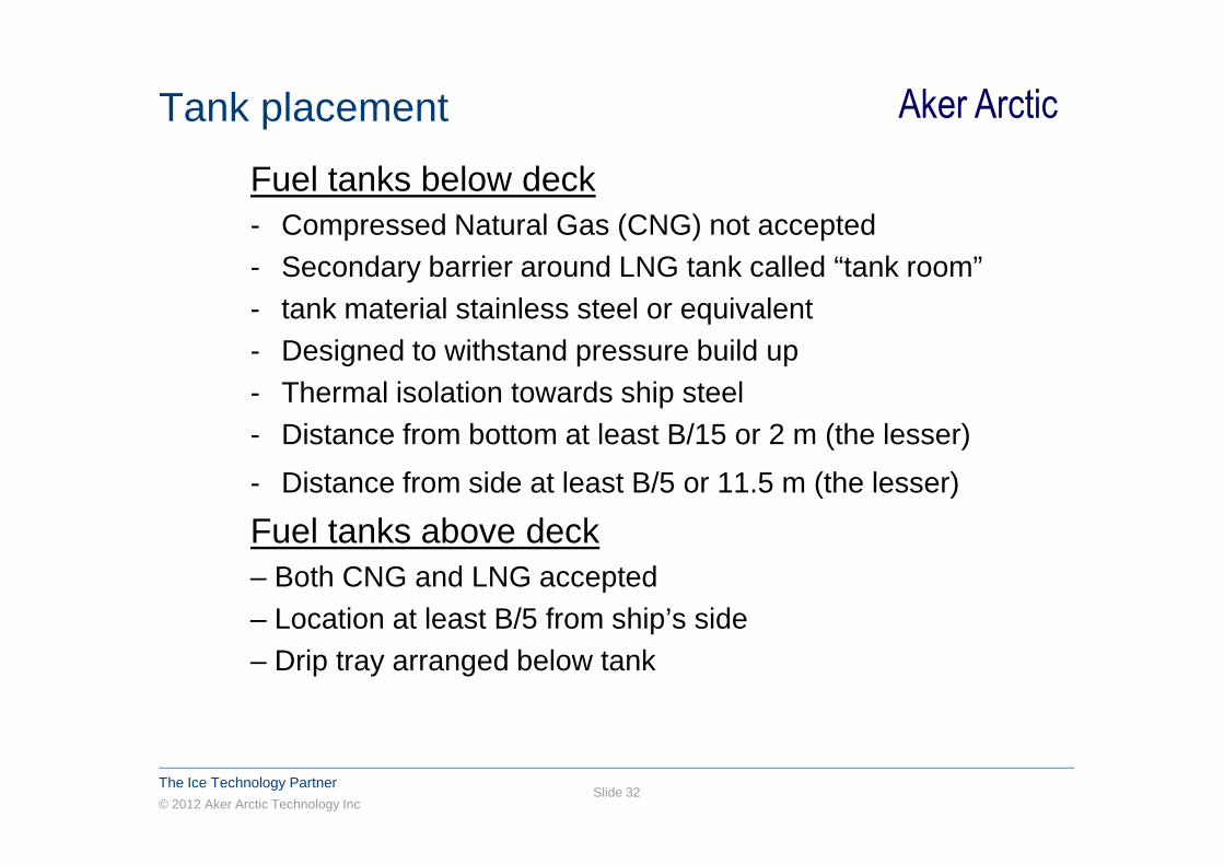
Aker ArcticTank placement
Fuel tanks below deck- Compressed Natural Gas (CNG) not accepted- Secondary barrier around LNG tank called “tank room”- tank material stainless steel or equivalent- Designed to withstand pressure build up- Thermal isolation towards ship steel- Distance from bottom at least B/15 or 2 m (the lesser)
© 2012 Aker Arctic Technology Inc
The Ice Technology PartnerSlide 32
- Distance from bottom at least B/15 or 2 m (the lesser)
- Distance from side at least B/5 or 11.5 m (the lesser)
Fuel tanks above deck– Both CNG and LNG accepted– Location at least B/5 from ship’s side– Drip tray arranged below tank
Aker ArcticMain principles of gas safety
� Explosion risk!
� Generally: Avoid gas in flammable mixture with oxygen and ignition sources in same location
� Limit the possibility for gas spreading in the ship
� Gas pipes through the ship to be in double enclosure
© 2012 Aker Arctic Technology Inc
The Ice Technology PartnerSlide 33
� Gas pipes through the ship to be in double enclosure
� Tank connections to be in special gas tight compartment
� High ventilation rates in spaces with gas sources
� Avoid gas concentration in the flammable range (5-15%)
� Suction ventilation to avoid leakage to surrounding spaces
� Limit the possibility for gas spreading in the ship
� Secondary barrier around gas tank as required by the IGC code
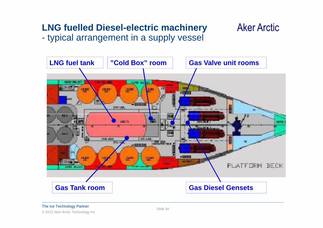
Aker ArcticLNG fuelled Diesel-electric machinery- typical arrangement in a supply vessel
LNG fuel tank ”Cold Box” room Gas Valve unit rooms
© 2012 Aker Arctic Technology Inc
The Ice Technology PartnerSlide 34
Gas Diesel GensetsGas Tank room

Aker ArcticLNG fuelling at shore base
© 2012 Aker Arctic Technology Inc
The Ice Technology PartnerSlide 35
� at large LNG plant
� from a local LNG fuelling station
� by an LNG bunker ship
� by an LNG truck (source from larger storage or plant)
++ proven concepts (ships, transfer hoses, procedures)
++ can serve other consumers in the area
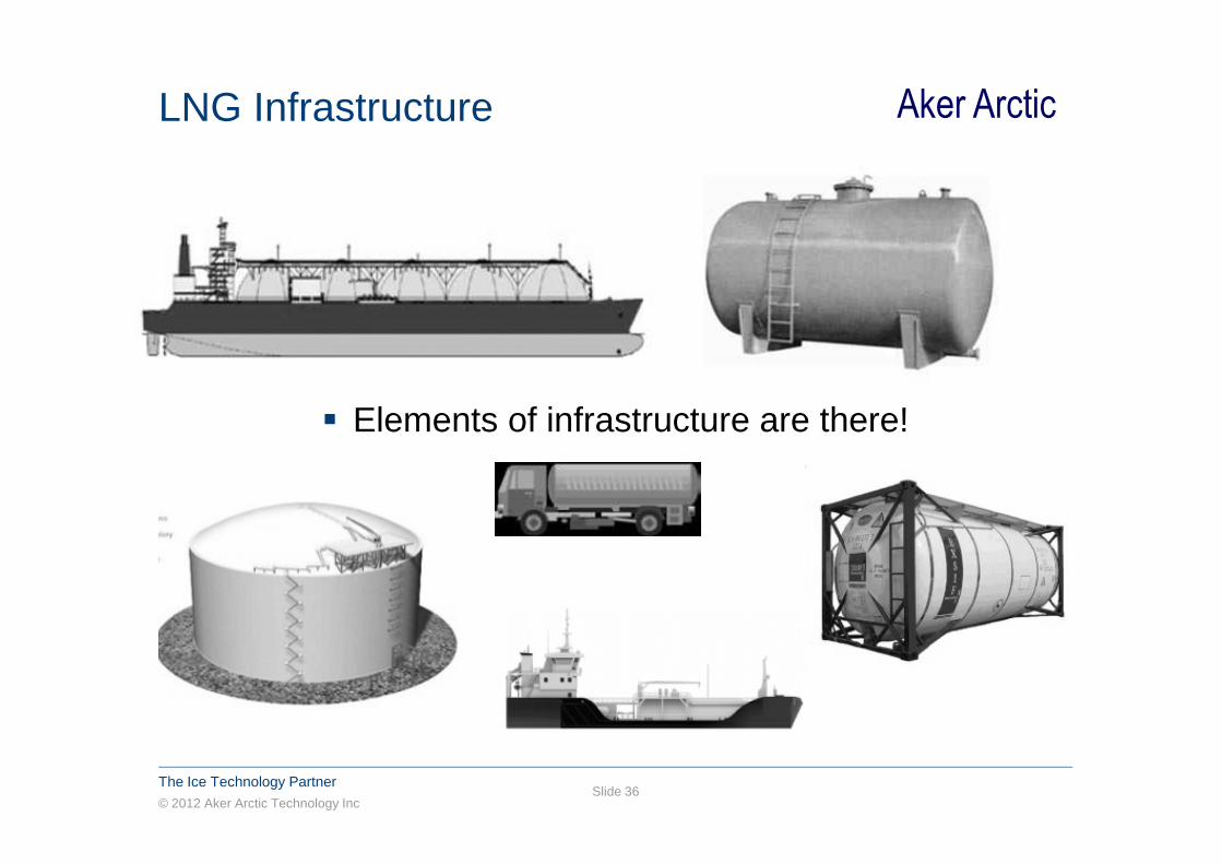
Aker ArcticLNG Infrastructure
� Elements of infrastructure are there!
© 2012 Aker Arctic Technology Inc
The Ice Technology PartnerSlide 36
� Elements of infrastructure are there!

Aker ArcticConclusions
� The use of natural gas as fuel is a promising and safe technology for complying with upcoming air emission limitations.
� LNG supply and distribution infrastructure needs to be built further in the Baltic Sea area.
� Recently approved ship concepts have been determined to provide an equivalent level of safety to the by using the IMO
© 2012 Aker Arctic Technology Inc
The Ice Technology PartnerSlide 37
provide an equivalent level of safety to the by using the IMO Interim Guidelines as a baseline standard.
� It is hoped that shipowners, designers and authorities will benefit from reviewing these considerations when developing conceptual designs for gas-fueled ships.
� Training and good co-operation between land and marine safety organisations need to be maintained to cover all phases of the LNG transportation and handling.
Aker ArcticAker Arctic Technology Inc
© 2012 Aker Arctic Technology Inc
The Ice Technology PartnerSlide 38
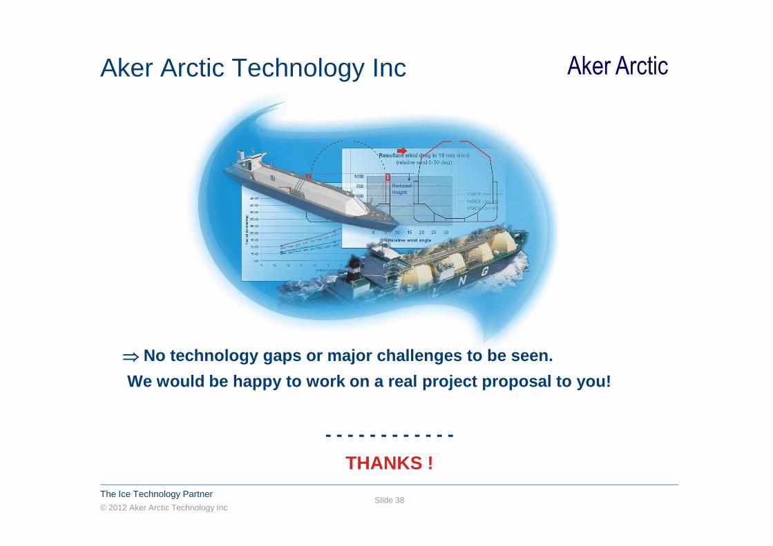
⇒⇒⇒⇒ No technology gaps or major challenges to be seen.
We would be happy to work on a real project proposa l to you!
- - - - - - - - - - - -
THANKS !

Aker Arctic
© 2012 Aker Arctic Technology Inc
The Ice Technology PartnerSlide 39
� Copyright of all published material including photographs, drawings and images in this document remains vested in Aker Arctic and third party contributors as appropriate. Accordingly, neither the whole nor any part of this document shall be reproduced in any form nor used in any manner without express prior permission and applicable acknowledgements. No trademark, copyright or other notice shall be altered or removed from any reproduction.


