12
3M FTTP Product Solutions 3M FTTP Product Solutions

3M FTTP Product Solutions3M FTTP Product Solutions

GROWING BANDWIDTH DEMAND OFFERS PROFIT POTENTIAL.
The demand for broadband connectivity and services to handle bandwidth-dependent
applications is exploding across many global markets. Services such as carrier-class
telephony, high-speed Internet access, voice-over-internet (VoIP), broadcast TV, HDTV,
real-time duplex video, online gaming and video-on-demand (VoD) represent substantial
new revenue opportunities for communications service providers and equipment
manufacturers (OEMs). Profitability and long-term competitive advantage in providing
these broadband services depend on active network development, careful technology
choices and effective resource management. A window of opportunity has opened,
and now is the time for action.
From the central office
and/or headend across the
outside plant into the customer
premises, 3M offers an
unmatched value proposition
for the physical-media layer.
From the central office
and/or headend across the
outside plant into the customer
premises, 3M offers an
unmatched value proposition
for the physical-media layer.

THE BEAUTY OF FIBER TO THE PREMISES.
Service providers are finding that Fiber to the Premises (FTTP) offers the ideal solution
to the challenges of delivering high bandwidth services to subscribers economically
and dependably. The cost of optical technology is declining, and FTTP provides the
ability to converge voice, video and data signals in a single high-speed pathway.
FTTP offers reduced network costs compared to copper, handles all current demands,
delivers essentially unlimited bandwidth and full compliance with coming services.
Freedom from EMI, RFI, cross-talk and most moisture problems makes FTTP easier
and less costly to maintain than copper-based networks. Elimination of outside plant
electronic components increases the reliability of networks and reduces their complexity
and life-cycle costs.
FIBER TO THE PREMISESProviding last-mile fiber connectivityfrom the central office to residential
and business subscribers.
PASSIVE OPTICAL NETWORKA totally passive, point-to-multi point
fiber-optic network that allows bandwidth sharing among users by means of splitters/couplers.
POINT-TO-POINTA fiber-optic network that delivers dedicated service from an active electronic element located in the
central office or outside plant environment to the subscriber.
FTTP
KEY TERMS
PON
P2P
(COUPLER)A passive photonic device
that divides and directs optical signals from one fiber to 2-32
individual fibers.
OPTICAL LINE TERMINAL An active component located in the CO used in Passive Optical
Networks to manage two-way multiple shared connections created
by splitters/couplers.
OPTICAL NETWORK TERMINALAn active device located at the curb or residence that converts optical
signals to electrical signals.
SPLITTER
OLT
ONT
3M OFFERS
UNMATCHED VALUE FOR
FTTP IMPLEMENTATION.
3M supports FTTP implementation
with unmatched history and
innovation in fiber optics
technology in the physical-media
layer—to leverage existing
infrastructure or install a
completely new network.
3M has decades of experience
in the telecommunications
access network, a full and
growing product portfolio and
industry-leading research and
development resources.
With 3M as an expert partner,
service providers and equipment
manufacturers can assemble
and implement effective,
future-proofed FTTP solutions
that meet customer demands
and protect the customer base.
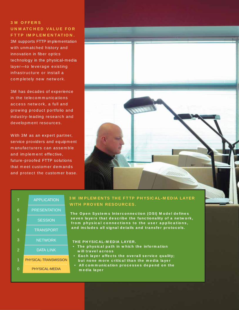
3M IMPLEMENTS THE FTTP PHYSICAL-MEDIA LAYER
WITH PROVEN RESOURCES.
The Open Systems Interconnection (OSI) Model definesseven layers that describe the functionality of a network,from physical connections to the user applications, and includes all signal details and transfer protocols.
THE PHYSICAL-MEDIA LAYER.• The physical path in which the information
will travel across• Each layer affects the overall service quality;
but none more critical than the media layer• All communication processes depend on the
media layer
APPLICATION
PRESENTATION
SESSION
TRANSPORT
NETWORK
DATA LINK
PHYSICAL-TRANSMISSION
PHYSICAL-MEDIA
7
6
5
4
3
2
1
0
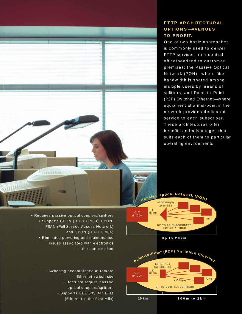
FFTTTTPP ARCHITECTURAL
OPTIONS—AVENUES
TO PROFIT.
One of two basic approaches
is commonly used to deliver
FTTP services from central
office/headend to customer
premises: the Passive Optical
Network (PON)—where fiber
bandwidth is shared among
multiple users by means of
splitters; and Point-to-Point
(P2P) Switched Ethernet—where
equipment at a mid-point in the
network provides dedicated
service to each subscriber.
These architectures offer
benefits and advantages that
suits each of them to particular
operating environments.
Point-to-Point (P2P) Switched Ethernet
10km
Up to 20km
UP TO 32 SUBSCRIBERS OUT OF A FIBER
OLT(in CO)
Passive Optical Network (PON)SPLITTER(S)up to 1:32
ONT
UP TO 1,000 SUBSCRIBERS
OLT(in CO)
1-10 fibers
1-2 fibers
1-2 fibers
ETHERNETSWITCH(ES)
ONT
300m to 2km
• Requires passive optical couplers/splitters
• Supports BPON (ITU-T G.983), EPON,
FSAN (Full Service Access Network)
and GPON (ITU-T G.984)
• Eliminates powering and maintenance
issues associated with electronics
in the outside plant
• Switching accomplished at remote
Ethernet switch site
• Does not require passive
optical couplers/splitters
• Supports IEEE 802.3ah EFM
(Ethernet in the First Mile)

FFTTTTPP OSP NETWORK
ARCHITECTURE
ALTERNATIVES.
Within the PON architecture,
one of three OSP architectures
can be selected:
• Point-to-point
• Centralized splitting
• Distributed splitting
Each has unique merits. In
all cases, PON equipment
communicates with the PSTN
and is connected to ATM or
Ethernet interfaces, with
switching accomplished in the
central office. Video services
are accessed by means of
a CATV headend or satellite
feed. Voice, video and data
signals are combined on fibers
by means of wave division
multiplexing and directed to
subscribers through passive
optical splitters.
A fourth FTTP architecture,
switched Ethernet, relies on
Ethernet switching equipment
located at a point in the
outside plant beyond the
central office, using Ethernet
protocol optimized for internet
traffic. This approach may offer
reduced overhead compared
to ATM, conserving bandwidth
and optimizing data capacity.
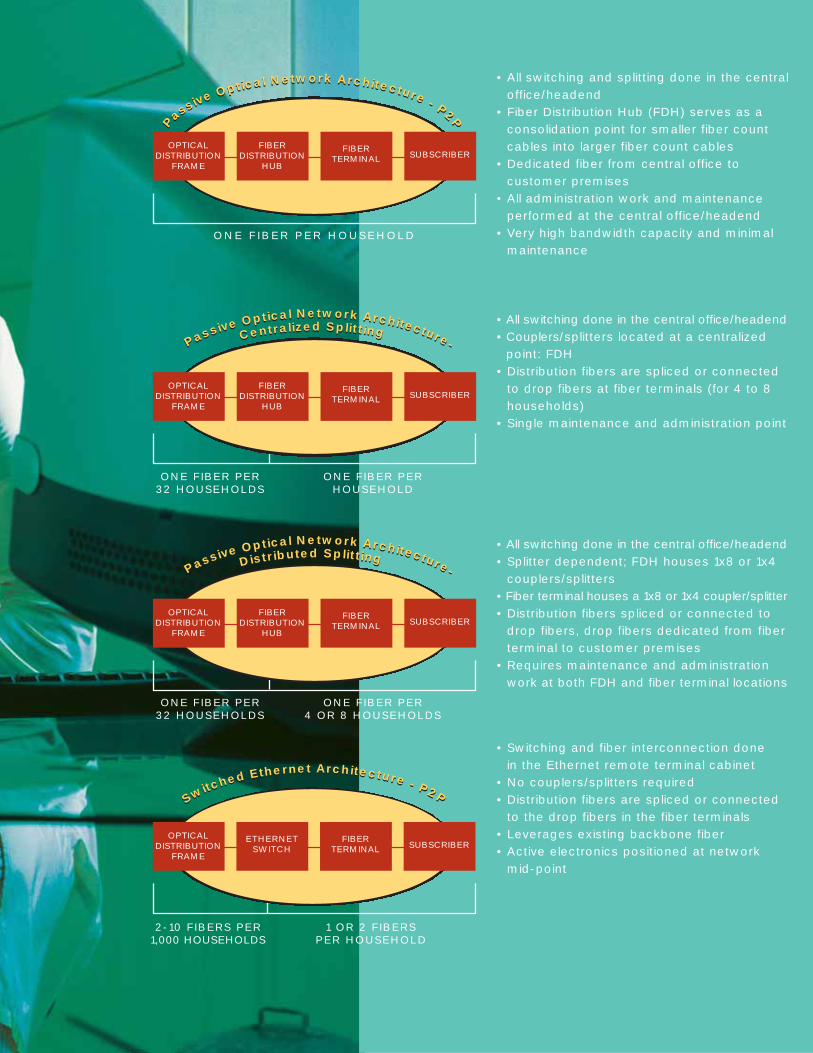
Switched Ethernet Architecture - P2PSwitched Ethernet Architecture - P2P
ONE F IBER PER HOUSEHOLD
OPTICALDISTRIBUTION
FRAME
FIBERDISTRIBUTION
HUB
FIBERTERMINAL SUBSCRIBER
P
assive Optical Network Architecture - P2PP
assive Optical Network Architecture - P2PPassive Optical Network Architecture-Centralized SplittingPassive Optical Network Architecture-Centralized Splitting
Passive Optical Network Architecture-Distributed SplittingPassive Optical Network Architecture-Distributed Splitting
• All switching and splitting done in the centraloffice/headend
• Fiber Distribution Hub (FDH) serves as aconsolidation point for smaller fiber countcables into larger fiber count cables
• Dedicated fiber from central office to customer premises
• All administration work and maintenanceperformed at the central office/headend
• Very high bandwidth capacity and minimalmaintenance
• All switching done in the central office/headend• Couplers/splitters located at a centralized
point: FDH • Distribution fibers are spliced or connected
to drop fibers at fiber terminals (for 4 to 8households)
• Single maintenance and administration point
• All switching done in the central office/headend• Splitter dependent; FDH houses 1x8 or 1x4
couplers/splitters• Fiber terminal houses a 1x8 or 1x4 coupler/splitter• Distribution fibers spliced or connected to
drop fibers, drop fibers dedicated from fiberterminal to customer premises
• Requires maintenance and administrationwork at both FDH and fiber terminal locations
• Switching and fiber interconnection done in the Ethernet remote terminal cabinet
• No couplers/splitters required• Distribution fibers are spliced or connected
to the drop fibers in the fiber terminals• Leverages existing backbone fiber• Active electronics positioned at network
mid-point
OPTICALDISTRIBUTION
FRAME
FIBERDISTRIBUTION
HUB
FIBERTERMINAL SUBSCRIBER
ONE FIBER PER HOUSEHOLD
ONE FIBER PER 32 HOUSEHOLDS
OPTICALDISTRIBUTION
FRAME
FIBERDISTRIBUTION
HUB
FIBERTERMINAL SUBSCRIBER
ONE FIBER PER 4 OR 8 HOUSEHOLDS
ONE FIBER PER 32 HOUSEHOLDS
OPTICALDISTRIBUTION
FRAME
FIBERTERMINAL
ETHERNETSWITCH SUBSCRIBER
1 OR 2 FIBERS PER HOUSEHOLD
2-10 FIBERS PER 1,000 HOUSEHOLDS
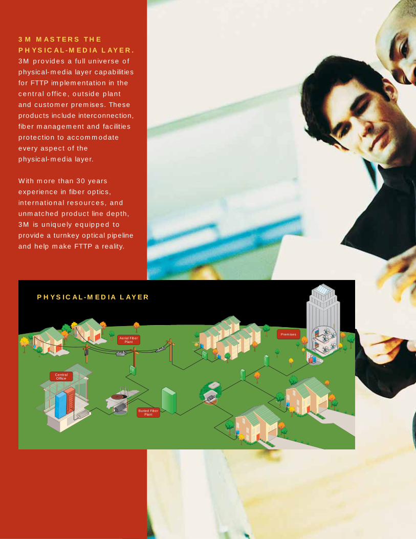
CentralOffice
Aerial FiberPlant
Buried FiberPlant
Premises
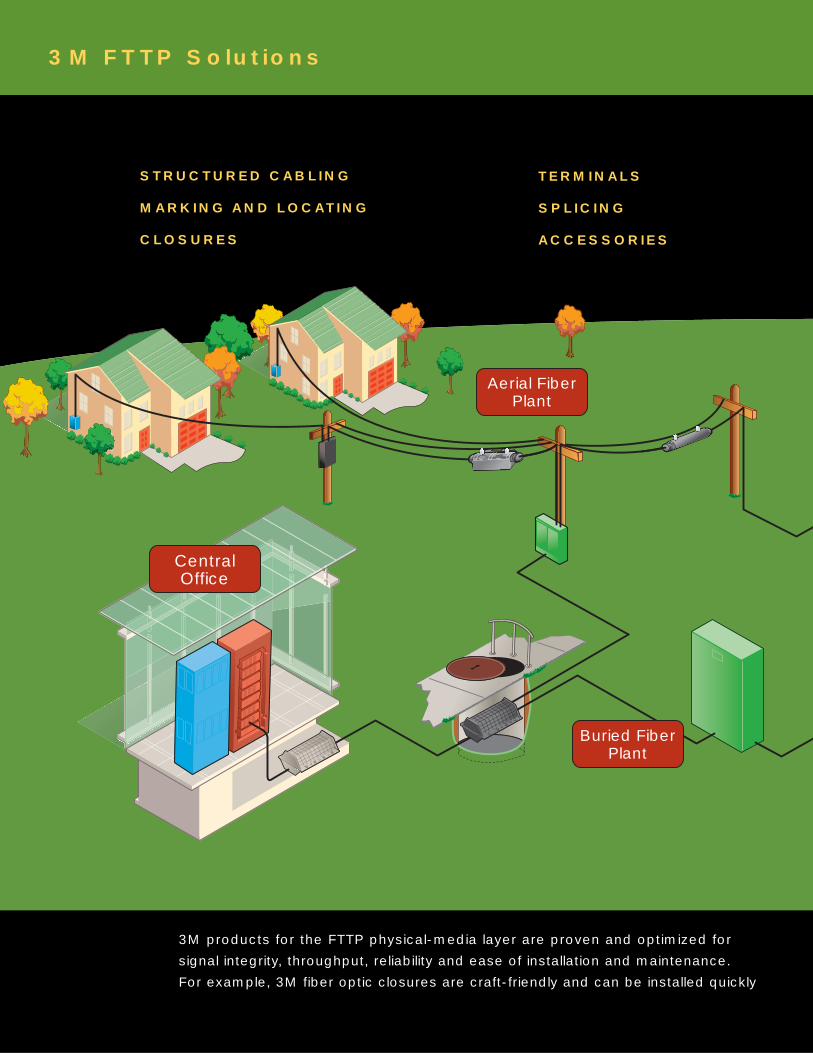
3M MASTERS THE
PHYSICAL-MEDIA LAYER.
3M provides a full universe of
physical-media layer capabilities
for FTTP implementation in the
central office, outside plant
and customer premises. These
products include interconnection,
fiber management and facilities
protection to accommodate
every aspect of the
physical-media layer.
With more than 30 years
experience in fiber optics,
international resources, and
unmatched product line depth,
3M is uniquely equipped to
provide a turnkey optical pipeline
and help make FTTP a reality.
PHYSICAL-MEDIA LAYER

3M PHYSICAL-MEDIA
LAYER CAPABILITIES.
FIBER SPLICINGFull range of discrete and
multi-fiber splices and tools for use throughoutthe FTTP network.
FIBERINTERCONNECT
A full range of 3M epoxy,epoxyless and hot meltconnectors in FC, SC andST configurations follows
tight design and manufacturingtolerances for a wide range of
uses. 3M™ GGP Cable Assembliesuse glass/glass/polymer fiber designed to bemore flexible and durable than standard fibers.
FIBERMANAGEMENT
Cross-connect and interconnect fiber cablemanagement systems (ODF,FDUs) and fiber organization
trays for central office/headend,outside plant, customer premises
or OEM applications.
FACILITIESPROTECTION
Sealed and free-breathingaerial, buried and underground fiber optic splice closures
and terminals; indoor and outdoor cabinets.
LOCATING ANDMARKING
Dynatel™ locating andmarking products offersolutions for fault finding,locating and permanent
marking and mapping ofburied facilities and points
of special interest.
CentralOffice
Aerial FiberPlant
Buried FiberPlant
3M FTTP Solutions
3M products for the FTTP physical-media layer are proven and optimized for
signal integrity, throughput, reliability and ease of installation and maintenance.
For example, 3M fiber optic closures are craft-friendly and can be installed quickly
TERMINALS
SPLICING
ACCESSORIES
STRUCTURED CABLING
MARKING AND LOCATING
CLOSURES
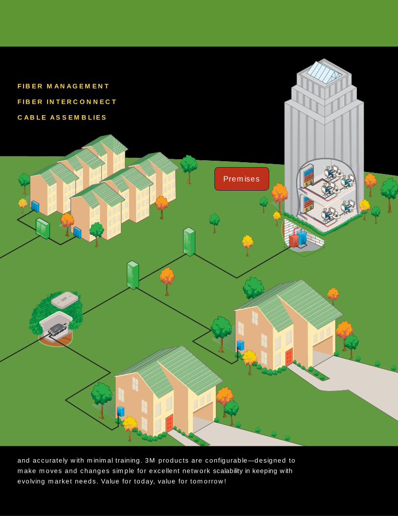
Premises
and accurately with minimal training. 3M products are configurable—designed to
make moves and changes simple for excellent network scalability in keeping with
evolving market needs. Value for today, value for tomorrow!
FIBER MANAGEMENT
FIBER INTERCONNECT
CABLE ASSEMBLIES

Whether you are a service provider or an FTTP equipment supplier,
get a head start on optimized FTTP network development with product and
development resources from 3M. You’ll enjoy the benefits of the broadest, most
functional and reliable line of products for the physical-media layer, supported with
long experience, global distribution, training support and responsive technical service.
Contact your local 3M representative for more information, or call the global
3M FTTP department at: 512/984 4533.
www.3MTelecommunications.com
Communication Markets Division3M Telecommunications6801 River Place Blvd.Austin, TX 78726-9000800/426 8688Fax 800/626 0329www.3MTelecommunications.com
3M and Dynatel are trademarks of 3M Company.
Important Notice
All statements, technical information, and recommendations related to 3M’s products are based on informationbelieved to be reliable, but the accuracy or completeness is not guaranteed. Before using this product, you mustevaluate it and determine if it is suitable for your intended application. You assume all risks and liability associatedwith such use. Any statements related to the product which are not contained in 3M’s current publications, or anycontrary statements contained on your purchase order shall have no force or effect unless expressly agreed upon, inwriting, by an authorized officer of 3M.
Warranty; Limited Remedy; Limited Liability. This product will be free from defects in material and manufacture for a period of 12 months from the date ofpurchase. 3M MAKES NO OTHER WARRANTIES INCLUDING, BUT NOT LIMITED TO, ANYIMPLIED WARRANTY OF MERCHANTABILITY OR FITNESS FOR A PARTICULAR PURPOSE. Ifthis product is defective within the warranty period stated above, your exclusive remedy shall be, at 3M’s option, toreplace or repair the 3M product or refund the purchase price of the 3M product. Except where prohibited by law,3M will not be liable for any loss or damage arising from this 3M product, whether direct, indirect, special,incidental or consequential regardless of thelegal theory asserted.
Litho in USA.
© 3M 2005 80-6113-1503-9 (2052.) K/LITHO-1
10% Post-consumer waste paper


