154
3PAR Confidential 3PAR InForm ® OS 2.3.1 Concepts Guide 3PAR, Inc. 4209 Technology Drive Fremont, CA 94538 USA Part No. 320-200112 Rev B February 2010
3PAR Confidential
3PAR InForm® OS 2.3.1Concepts Guide
3PAR, Inc.4209 Technology DriveFremont, CA 94538 USA
Part No. 320-200112 Rev BFebruary 2010
Revision NoticesThis is the second release of this manual. A complete revision history of this document is provided at the end of this document.
ChangesThe material in this document is for information only and is subject to change without notice. While reasonable efforts have been made in the preparation of this document to assure its accuracy, 3PAR, Inc. assumes no liability resulting from errors or omissions in this document or from the use of the information contained herein.3PAR reserves the right to make changes in the product design without reservation and without notification to its users.
Updates to the Documentation at 3PAR CentralAny updates to this document, or to other 3PAR technical documents, can be found by logging in to 3PAR Central’s Document Control System from 3PAR’s Support page at http://support.3PAR.com
3PAR Technical Support and ServicesContact your local service provider for technical support and services at: http://www.3PAR.com/services.html.
Sales and Ordering InformationFor sales and ordering information, contact:3PAR, Inc. 4209 Technology DriveFremont, CA 94538 USATelephone: 510-413-5999Fax: 510-413-5699Email: [email protected]
Reader Comments and SuggestionsPlease email your comments and suggestions about this document to [email protected].
Copyrights © 2007-2010 3PAR, Inc. All rights reserved. No part of this publication may be reproduced, stored in a retrieval system, or transmitted in any form or by any means, electronic, mechanical, photocopying, recording or otherwise, without the prior written consent of 3PAR, Inc., 4209 Technology Drive, Fremont, CA 94538. By way of exception to the foregoing, the user may print one copy of electronic material for personal use only.
JClass Chart Copyright © 2000-2002 by Sitraka Inc. All Rights Reserved. THIS SOFTWARE IS PROVIDED BY THE AUTHOR AND CONTRIBUTORS "AS IS" AND ANY EXPRESS OR IMPLIED WARRANTIES, INCLUDING, BUT NOT LIMITED TO, THE IMPLIED WARRANTIES OF MERCHANTABILITY AND FITNESS FOR A PARTICULAR PURPOSE ARE DISCLAIMED. IN NO EVENT SHALL THE AUTHOR OR CONTRIBUTORS BE LIABLE FOR ANY DIRECT, INDIRECT, INCIDENTAL, SPECIAL, EXEMPLARY, OR CONSEQUENTIAL DAMAGES (INCLUDING, BUT NOT LIMITED TO, PROCUREMENT OF SUBSTITUTE GOODS OR SERVICES; LOSS OF USE, DATA, OR PROFITS; OR BUSINESS INTERRUPTION) HOWEVER CAUSED AND ON ANY THEORY OF LIABILITY, WHETHER IN CONTRACT, STRICT LIABILITY, OR TORT (INCLUDING NEGLIGENCE OR OTHERWISE) ARISING IN ANY WAY OUT OF THE USE OF THIS SOFTWARE, EVEN IF ADVISED OF THE POSSIBILITY OF SUCH DAMAGE.
log4j, Copyright © 1999 The Apache Software Foundation. All rights reserved. Redistribution and use in source and binary forms, with or without modification, are permitted provided that the following conditions are met:1. Redistributions of source code must retain the above copyright notice, this list of conditions and the following disclaimer.2. Redistributions in binary form must reproduce the above copyright notice, this list of conditions and the following disclaimer in the documentation and/or other materials provided with the distribution.3. The end-user documentation included with the redistribution, if any, must include the following acknowledgment: "This product includes software developed by the Apache Software Foundation (http://www.apache.org/)."Alternately, this acknowledgment may appear in the software itself, if and wherever such third-party acknowledgments normally appear.4. The names "log4j" and "Apache Software Foundation" must not be used to endorse or promote products derived from this software without prior written permission. For written permission, please contact [email protected].
3PAR Confidential

5. Products derived from this software may not be called "Apache", nor may "Apache" appear in their name, without prior written permission of the Apache Software Foundation.THIS SOFTWARE IS PROVIDED ``AS IS'' AND ANY EXPRESSED OR IMPLIED WARRANTIES, INCLUDING, BUT NOT LIMITED TO, THE IMPLIED WARRANTIES OF MERCHANTABILITY AND FITNESS FOR A PARTICULAR PURPOSE ARE DISCLAIMED. IN NO EVENT SHALL THE APACHE SOFTWARE FOUNDATION OR ITS CONTRIBUTORS BE LIABLE FOR ANY DIRECT, INDIRECT, INCIDENTAL, SPECIAL, EXEMPLARY, OR CONSEQUENTIAL DAMAGES (INCLUDING, BUT NOT LIMITED TO, PROCUREMENT OF SUBSTITUTE GOODS OR SERVICES; LOSS OF USE, DATA, OR PROFITS; OR BUSINESS INTERRUPTION) HOWEVER CAUSED AND ON ANY THEORY OF LIABILITY, WHETHER IN CONTRACT, STRICT LIABILITY, OR TORT (INCLUDING NEGLIGENCE OR OTHERWISE) ARISING IN ANY WAY OUT OF THE USE OF THIS SOFTWARE, EVEN IF ADVISED OF THE POSSIBILITY OF SUCH DAMAGE.This software consists of voluntary contributions made by many individuals on behalf of the Apache Software Foundation. For more information on the Apache Software Foundation, please see <http://www.apache.org/>.
NetBSD NoticesCertain sections of the InForm OS that handle crash dumps were derived from NetBSD under the BSD license. 3PAR, Inc. provides the following notices in accordance with the original license.Copyright (c) 1996, 1997, 1998, 2001 The NetBSD Foundation, Inc. All rights reserved.The code obtained from NetBSD is derived from software contributed to The NetBSD Foundation by Charles M. Hannum and by Jason R. Thorpe of the Numerical Aerospace Simulation Facility, NASA Ames Research Center.Redistribution and use in source and binary forms, with or without modification, are permitted provided that the following conditions are met:1 Redistributions of source code must retain the above copyright notice, this list of conditions and the following disclaimer.2 Redistributions in binary form must reproduce the above copyright notice, this list of conditions and the following disclaimer in
the documentation and/or other materials provided with the distribution.3 All advertising materials mentioning features or use of this software must display the following acknowledgement:
This product includes software developed by the NetBSD Foundation, Inc. and its contributors.4 Neither the name of The NetBSD Foundation nor the names of its contributors may be used to endorse or promote products
derived from this software without specific prior written permission.Copyright (c) 1998, 1999, 2000, 2001 Manuel Bouyer.Redistribution and use in source and binary forms, with or without modification, are permitted provided that the following conditions are met:1 Redistributions of source code must retain the above copyright notice, this list of conditions and the following disclaimer.2 Redistributions in binary form must reproduce the above copyright notice, this list of conditions and the following disclaimer in
the documentation and/or other materials provided with the distribution.3 All advertising materials mentioning features or use of this software must display the following acknowledgement:
This product includes software developed by the University of California, Berkeley and its contributors.4 Neither the name of the University nor the names of its contributors may be used to endorse or promote products derived from
this software without specific prior written permission.Copyright (c) 1996, 1998 Christopher G. Demetriou. All rights reserved.Redistribution and use in source and binary forms, with or without modification, are permitted provided that the following conditions are met:1 Redistributions of source code must retain the above copyright notice, this list of conditions and the following disclaimer.2 Redistributions in binary form must reproduce the above copyright notice, this list of conditions and the following disclaimer in
the documentation and/or other materials provided with the distribution.3 All advertising materials mentioning features or use of this software must display the following acknowledgement:
This product includes software developed by Christopher G. Demetriou for the NetBSD Project.4 The name of the author may not be used to endorse or promote products derived from this software without specific prior written
permission.Copyright (c) 1998 The NetBSD Foundation, Inc. All rights reserved.The code obtained from NetBSD is derived from software contributed to The NetBSD Foundation by Charles M. Hannum, by Onno van der Linden and by Manuel Bouyer.Redistribution and use in source and binary forms, with or without modification, are permitted provided that the following conditions are met:1 Redistributions of source code must retain the above copyright notice, this list of conditions and the following disclaimer.
3PAR Confidential

2 Redistributions in binary form must reproduce the above copyright notice, this list of conditions and the following disclaimer in the documentation and/or other materials provided with the distribution.
3 All advertising materials mentioning features or use of this software must display the following acknowledgement: This product includes software developed by the NetBSD Foundation, Inc. and its contributors.
4 Neither the name of The NetBSD Foundation nor the names of its contributors may be used to endorse or promote products derived from this software without specific prior written permission.
Copyright (c) 1991 The Regents of the University of California. All rights reserved.The code obtained from NetBSD is derived from software contributed to Berkeley by William Jolitz. Redistribution and use in source and binary forms, with or without modification, are permitted provided that the following conditions are met:1 Redistributions of source code must retain the above copyright notice, this list of conditions and the following disclaimer.2 Redistributions in binary form must reproduce the above copyright notice, this list of conditions and the following disclaimer in
the documentation and/or other materials provided with the distribution.3 All advertising materials mentioning features or use of this software must display the following acknowledgement:
This product includes software developed by the University of California, Berkeley and its contributors.4 Neither the name of the University nor the names of its contributors may be used to endorse or promote products derived from
this software without specific prior written permission.The following applies to all of these notices:THIS SOFTWARE IS PROVIDED BY THE COPYRIGHT OWNERS LISTED ABOVE AND CONTRIBUTORS ``AS IS'' AND ANY EXPRESS OR IMPLIED WARRANTIES, INCLUDING, BUT NOT LIMITED TO, THE IMPLIED WARRANTIES OF MERCHANTABILITY AND FITNESS FOR A PARTICULAR PURPOSE ARE DISCLAIMED. IN NO EVENT SHALL THE REGENTS OR CONTRIBUTORS BE LIABLE FOR ANY DIRECT, INDIRECT, INCIDENTAL, SPECIAL, EXEMPLARY, OR CONSEQUENTIAL DAMAGES (INCLUDING, BUT NOT LIMITED TO, PROCUREMENT OF SUBSTITUTE GOODS OR SERVICES; LOSS OF USE, DATA, OR PROFITS; OR BUSINESS INTERRUPTION) HOWEVER CAUSED AND ON ANY THEORY OF LIABILITY, WHETHER IN CONTRACT, STRICT LIABILITY, OR TORT (INCLUDING NEGLIGENCE OR OTHERWISE) ARISING IN ANY WAY OUT OF THE USE OF THIS SOFTWARE, EVEN IF ADVISED OF THE POSSIBILITY OF SUCH DAMAGE.
GNU General Public License MaterialsThe InForm OS uses the Linux kernel and lkcdutils crash dump utilities. The Linux kernel and lkcdutils crash dump utilities have been modified slightly by 3PAR, Inc. and, as modified, are licensed under the GNU General Public License.Copyright © 2002-2003 3PAR, Inc.A copy of the GNU General Public License is available on the CD-ROM provided by 3PAR and may additionally be obtained at http://www.fsf.org/licenses/gpl.html. As required by this license, for a period of three years after you receive the Linux kernel and lkcdutils crash dump utilities from 3PAR, a copy of the source code for such software, as modified, may be obtained from 3PAR at 3PAR’s cost of providing you with such code.The InForm OS uses a Linux gigabit adaptor base driver distributed by Intel under the GNU GPL. The driver has been modified slightly by 3PAR, Inc. and, as modified, is licensed under the GNU GPL.Copyright © 2002, 2003, 3PAR, Inc.A copy of the GNU GPL is available on the CD-ROM provided by 3PAR and may additionally be obtained at http://www.fsf.org/licenses/gpl.html. As required by this license, for a period of three years after you receive the Linux gigabit adapter base driver from 3PAR, a copy of the source code for such software, as modified, may be obtained from 3PAR at 3PAR’s cost of providing you with such code.
The InForm OS contains hardware and firmware protocol definitions for the LSI Logic Fusion MPT architecture. These definitions are licensed under the GNU GPL.Copyright © 2000-2002 LSI Logic Corporation.A copy of the GNU GPL is available on the CD-ROM provided by 3PAR and may additionally be obtained at http://www.fsf.org/licenses/gpl.html. As required by this license, for a period of three years after you receive these definitions from 3PAR, a copy of the source code may be obtained from 3PAR at 3PAR's cost of providing you with such code.
GNU Lesser General Public License MaterialsThe InForm OS uses the following unmodified GNU LGPL libraries: glibc (Copyright © 1991-2001 Free Software Foundation, Inc), libgmp (Copyright © 1991, 1993-2002 Free Software Foundation, Inc), libncurses (Copyright © 1998 Free Software Foundation, Inc), libpopt (Copyright © Red Hat Software), and libstdc++ (Copyright © 1986-2000 Free Software Foundation, Inc). These libraries are licensed under the GNU Lesser General Public License.
3PAR Confidential

A copy of the GNU Lesser General Public License is available on the CD-ROM provided by 3PAR and may additionally be obtained at http://www.fsf.org/licenses/lgpl.html. A copy of the source code for such software may be obtained from 3PAR or from http://www.debian.org
OpenSSL License MaterialsThe InForm OS uses the unmodified libssl OpenSSL library. This library is licensed under dual licenses, the OpenSSL License and the SSLeay License.Copyright (c) 1998-1999 The OpenSSL Project. All rights reserved.Redistribution and use of the libssl OpenSSL library in source and binary forms, with or without modification, is permitted provided that the following conditionsare met:1. Redistributions of source code must retain the above copyright notice, this list of conditions and the following disclaimer. 2. Redistributions in binary form must reproduce the above copyright notice, this list of conditions and the following disclaimer in the documentation and/or other materials provided with the distribution.3. All advertising materials mentioning features or use of this software must display the following acknowledgment: "This product includes software developed by the OpenSSL Project for use in the OpenSSL Toolkit. (http://www.openssl.org/)"4. The names "OpenSSL Toolkit" and "OpenSSL Project" must not be used endorse or promote products derived from this software without prior written permission. For written permission, please contact [email protected]. Products derived from this software may not be called "OpenSSL" nor may "OpenSSL" appear in their names without prior written permission of the OpenSSL Project.6. Redistributions of any form whatsoever must retain the following acknowledgment: "This product includes software developed by the OpenSSL Project for use in the OpenSSL Toolkit (http://www.openssl.org/)"
THIS SOFTWARE IS PROVIDED BY THE OpenSSL PROJECT ``AS IS'' AND ANY EXPRESSED OR IMPLIED WARRANTIES, INCLUDING, BUT NOT LIMITED TO, THE IMPLIED WARRANTIES OF MERCHANTABILITY AND FITNESS FOR A PARTICULAR PURPOSE ARE DISCLAIMED. IN NO EVENT SHALL THE OpenSSL PROJECT OR ITS CONTRIBUTORS BE LIABLE FOR ANY DIRECT, INDIRECT, INCIDENTAL, SPECIAL, EXEMPLARY, OR CONSEQUENTIAL DAMAGES (INCLUDING, BUT NOT LIMITED TO, PROCUREMENT OF SUBSTITUTE GOODS OR SERVICES; LOSS OF USE, DATA, OR PROFITS; OR BUSINESS INTERRUPTION) HOWEVER CAUSED AND ON ANY THEORY OF LIABILITY, WHETHER IN CONTRACT, STRICT LIABILITY, OR TORT (INCLUDING NEGLIGENCE OR OTHERWISE) ARISING IN ANY WAY OUT OF THE USE OF THIS SOFTWARE, EVEN IF ADVISED OF THE POSSIBILITY OF SUCH DAMAGE.______________________________________________________________________This product includes cryptographic software written by Eric Young ([email protected]). This product includes software written by TimHudson ([email protected]).
Original SSLeay LicenseCopyright (C) 1995-1998 Eric Young ([email protected])All rights reserved.
This package is an SSL implementation writtenby Eric Young ([email protected]).The implementation was written so as to conform with Netscape's SSL.
This library is free for commercial and non-commercial use as long asthe following conditions are adhered to. The following conditionsapply to all code found in this distribution, be it the RC4, RSA,
3PAR Confidential
lhash, DES, etc., code; not just the SSL code. The SSL documentationincluded with this distribution is covered by the same copyright termsexcept that the holder is Tim Hudson ([email protected]).Copyright remains Eric Young's, and as such any Copyright notices inthe code are not to be removed.If this package is used in a product, Eric Young should be given attributionas the author of the parts of the library used.This can be in the form of a textual message at program startup orin documentation (online or textual) provided with the package. Redistribution and use of the libssl OpenSSL library in source and binary forms, with or without modification, is permitted provided that the following conditionsare met:1. Redistributions of source code must retain the copyright notice, this list of conditions and the following disclaimer.2. Redistributions in binary form must reproduce the above copyright notice, this list of conditions and the following disclaimer in the documentation and/or other materials provided with the distribution.3. All advertising materials mentioning features or use of this software must display the following acknowledgement: "This product includes cryptographic software written by Eric Young ([email protected])" The word 'cryptographic' can be left out if the routines from the library being used are not cryptographic related. 4. If you include any Windows specific code (or a derivative thereof) from the apps directory (application code) you must include an acknowledgement: "This product includes software written by Tim Hudson ([email protected])." THIS SOFTWARE IS PROVIDED BY ERIC YOUNG "AS IS" AND ANY EXPRESS OR IMPLIED WARRANTIES, INCLUDING, BUT NOT LIMITED TO, THE IMPLIED WARRANTIES OF MERCHANTABILITY AND FITNESS FOR A PARTICULAR PURPOSE ARE DISCLAIMED. IN NO EVENT SHALL THE AUTHOR OR CONTRIBUTORS BE LIABLE FOR ANY DIRECT, INDIRECT, INCIDENTAL, SPECIAL, EXEMPLARY, OR CONSEQUENTIAL DAMAGES (INCLUDING, BUT NOT LIMITED TO, PROCUREMENT OF SUBSTITUTE GOODS OR SERVICES; LOSS OF USE, DATA, OR PROFITS; OR BUSINESS INTERRUPTION) HOWEVER CAUSED AND ON ANY THEORY OF LIABILITY, WHETHER IN CONTRACT, STRICT LIABILITY, OR TORT (INCLUDING NEGLIGENCE OR OTHERWISE) ARISING IN ANY WAY OUT OF THE USE OF THIS SOFTWARE, EVEN IF ADVISED OF THE POSSIBILITY OFSUCH DAMAGE.
The license and distribution terms for any publicly available version or derivative of this code cannot be changed. i.e., this code cannot simply be copied and put under another distribution license [including the GNU Public License.]
Other Open Source MaterialsThe InForm OS uses the unmodified zlib library.Copyright © 1995-1998 Jean-loup Gailly and Mark Adler. This software is provided 'as-is', without any express or implied warranty. In no event will the authors be held liable for any damages arising from the use of this software.Permission is granted to anyone to use this software for any purpose, including commercial applications, and to alter it and redistribute it freely, subject to the following restrictions:1.The origin of this software must not be misrepresented; you must not claim that you wrote the original software. If you use this software in a product, an acknowledgment in the product documentation would be appreciated but is not required.2.Altered source versions must be plainly marked as such, and must not be misrepresented as being the original software.3.This notice may not be removed or altered from any sourcedistribution.
3PAR Confidential

Other Licensed MaterialsThe snmpagent within the InServ contains copyright materials from AdventNet, Inc. http://www.adventnet.com. All rights to such copyright material rest with AdventNet.
Trademarks3PAR, InServ, InForm, InSpire and Serving Information are registered trademarks of 3PAR, Inc.Intel and Pentium are registered trademarks of Intel Corporation.Linux is a registered trademark of Linus Torvalds.Microsoft, Windows, and Windows NT, Exchange Server, and SQL Server are either registered trademarks or trademarks of Microsoft Corporation.Linux is a registered trademark of Linus Torvalds.Redhat is a registered trademark of Red Hat, Inc.SuSE is a registered trademark of Novell, Inc.Oracle is a registered trademark of Oracle Corporation.Sun, Solaris, and Java are trademarks of Sun Microsystems, Inc.UNIX is a registered trademark of The Open Group.All other trademarks and registered trademarks are owned by their respective owners.
3PAR Confidential

3PAR Confidential

InForm OS Version 2.3.1 3PAR InForm OS Concepts Guide
Table of Contents
1 Introduction
1.1 Audience 1.1
1.2 User Interfaces 1.2
1.3 Units of Measure 1.2
1.4 Related Documentation 1.3
1.5 Organization 1.4
1.6 Typographical Conventions 1.5
1.7 Advisories 1.6
2 Overview
2.1 3PAR Storage Concepts and Terminology 2.2
2.1.1 Physical Disks 2.4
2.1.2 Chunklets 2.4
2.1.3 Logical Disks 2.4
2.1.4 Common Provisioning Groups 2.4
2.1.5 Virtual Volumes 2.5
2.2 3PAR InForm Software 2.7
2.2.1 InForm Software Suite 2.7
2.2.2 Optional Software Features 2.8
2.2.3 Host-Based Software 2.10
3PAR ConfidentialiiiTable of Contents

iv
3PAR InForm OS Concepts Guide InForm OS Version 2.3.1
3 InServ Storage Server Users
3.1 Overview 3.1
3.2 Local Users 3.2
3.3 Domain Users 3.3
3.4 LDAP Users 3.4
4 LDAP
4.1 Overview 4.1
4.1.1 Active Directory 4.2
4.1.2 OpenLDAP 4.3
4.2 LDAP Users 4.3
4.3 LDAP Server Data Organization 4.4
4.4 LDAP and Domains 4.4
4.5 LDAP Authentication and Authorization 4.5
4.5.1 Authentication 4.5
4.5.2 Authorization 4.6
4.5.3 Authorization on Systems Using 3PAR Virtual Domains 4.7
5 3PAR Virtual Domains
5.1 Overview 5.1
5.2 Domain Types and User Classes 5.3
5.2.1 Domain Type 5.3
5.2.2 User Class 5.3
5.3 Users and Domain Privileges 5.4
5.4 Object and Domain Association Rules 5.5
5.5 The Default and Current Domains 5.5
6 Ports and Hosts
6.1 Overview 6.2
6.2 About Ports 6.2
6.2.1 Fibre Channel Ports 6.3
Table of Contents
3PAR Confidential

InForm OS Version 2.3.1 3PAR InForm OS Concepts Guide
6.2.2 iSCSI Ports 6.3
6.2.3 Gigabit Ethernet Ports 6.3
6.3 Port Location Formats 6.3
6.4 Port Target, Initiator, and Peer Modes 6.4
6.5 Active and Inactive Hosts 6.4
6.6 Adding and Removing Hosts 6.5
6.7 Host Personas 6.5
6.7.1 Legacy Host Personas 6.7
6.8 The Host Explorer Agent 6.8
7 Chunklets
7.1 Overview 7.1
7.2 Physical Disk Chunklets 7.2
7.3 Spare Chunklets 7.2
8 Logical Disks
8.1 Overview 8.1
8.2 Logical Disks and Common Provisioning Groups 8.2
8.3 Logical Disk Types 8.2
8.4 RAID Types 8.3
8.4.1 RAID 0 8.4
8.4.2 RAID 1 and 10 8.4
8.4.3 RAID 5 and 50 8.5
8.4.4 RAID Multi-Parity 8.6
8.5 Logical Disk Size and RAID Types 8.8
8.6 Logical Disk Size and Virtual Volumes 8.9
8.7 Logical Disk Size and Common Provisioning Groups 8.9
9 Common Provisioning Groups
9.1 Overview 9.2
9.2 Precautions and Planning 9.3
vTable of Contents
3PAR Confidential

vi
3PAR InForm OS Concepts Guide InForm OS Version 2.3.1
9.2.1 Growth Increments, Warnings, and Limits 9.3
9.2.2 Growth Increment 9.4
9.2.3 Growth Warning 9.5
9.2.4 Growth Limit 9.5
9.3 System Guidelines for Creating CPGs 9.6
9.4 Volume Types Associated with CPGs 9.7
10 Virtual Volumes
10.1 Overview 10.1
10.2 Virtual Volume Types 10.2
10.2.1 Administrative Volumes 10.3
10.2.2 Fully-Provisioned Virtual Volumes 10.3
10.2.3 Thinly-Provisioned Virtual Volumes 10.4
10.3 Physical Copies 10.6
10.4 Virtual Copy Snapshots 10.7
10.4.1 Virtual Copy Snapshot Relationships 10.7
10.5 Exporting Virtual Volumes 10.11
10.5.1 VLUN Templates and Active VLUNs 10.11
10.5.2 VLUN Template Types 10.11
11 Reclaiming Unused Space
11.1 Overview 11.1
11.2 Reclaiming Unmapped Logical Disk Space from CPGs 11.2
11.3 Reclaiming Unmapped Logical Disk Space from Volumes 11.3
11.4 Automatically Reclaiming Unused Snapshot Space from Volumes 11.3
11.5 Manually Reclaiming Unused Snapshot Space from Volumes 11.4
11.6 Deleted Volume’s Snapshot Space 11.4
12 Enhanced Storage Applications
12.1 Overview 12.2
12.2 mySnapshot 12.2
Table of Contents
3PAR Confidential

InForm OS Version 2.3.1 3PAR InForm OS Concepts Guide
12.3 Dynamic Optimization 12.3
12.4 System Tuner 12.4
12.5 Thin Conversion 12.5
12.5.1 Assessment 12.6
12.5.2 Data Preparation 12.6
12.5.3 Zeroing Unused Space 12.6
12.5.4 Creating a Physical Copy 12.6
12.6 Thin Persistence 12.7
12.7 Thin Copy Reclamation 12.8
12.8 Virtual Lock 12.8
13 3PAR InServ Storage Server Hardware
13.1 Overview 13.1
13.2 Identifying Storage Server Components 13.2
13.3 Physical Disks 13.4
13.3.1 Disk Replacement 13.6
13.4 Drive Cage Models 13.6
13.4.1 DC2 and DC4 Drive Cages 13.6
13.4.2 DC2 and DC4 Ports and Cabling 13.8
13.4.3 DC3 Drive Cage 13.9
13.4.4 DC3 Ports and Cabling 13.9
13.5 Controller Node Overview 13.10
13.5.1 S-Class and T-Class Node Numbering 13.12
13.5.2 S-Class and T-Class Controller Node Numbering 13.12
13.5.3 E-Class and F-Class Controller Node Numbering 13.14
14 SNMP
14.1 Overview 14.1
14.2 About SNMP 14.2
14.3 SNMP Managers 14.2
14.4 The 3PAR SNMP Agent 14.3
viiTable of Contents
3PAR Confidential

viii
3PAR InForm OS Concepts Guide InForm OS Version 2.3.1
14.4.1 Standard Compliance 14.3
14.4.2 Supported MIBs 14.3
15 The 3PAR InForm CIM API
15.1 Overview 15.2
15.2 About SMI-S 15.2
15.3 About the WBEM Initiative 15.3
15.4 3PAR InForm CIM Support 15.4
15.4.1 Standard Compliance 15.4
15.4.2 SMI-S Profiles 15.4
15.4.3 Supported Extensions 15.4
15.4.4 CIM Indications 15.4
GL Glossary
IX Index
RH Revision History
Table of Contents
3PAR Confidential

InForm OS Version 2.3.1 3PAR InForm OS Concepts Guide
1Introduction
In this chapter
1.1 Audience 1.1
1.2 User Interfaces 1.2
1.3 Units of Measure 1.2
1.4 Related Documentation 1.3
1.5 Organization 1.4
1.6 Typographical Conventions 1.5
1.7 Advisories 1.6
1.1 AudienceThis conceptual guide is for all levels of system and storage administrators. Anyone who plans
storage policies, configures storage resources, or monitors the storage usage of 3PAR InServ
Storage Servers should read this guide.
1.1Introduction
3PAR Confidential
1.2
3PAR InForm OS Concepts Guide InForm OS Version 2.3.1
1.2 User InterfacesTwo user interfaces are available for the administration of 3PAR InServ Storage Servers: the
3PAR InForm Command Line Interface (CLI) and the 3PAR InForm Management Console. Unless
otherwise stated, all tasks can be performed with both the CLI and the Management Console.
Refer to the 3PAR InForm OS CLI Administrator’s Manual and the 3PAR InForm Management
Console Online Help for instructions on how to perform the tasks described at a conceptual
level in this guide.
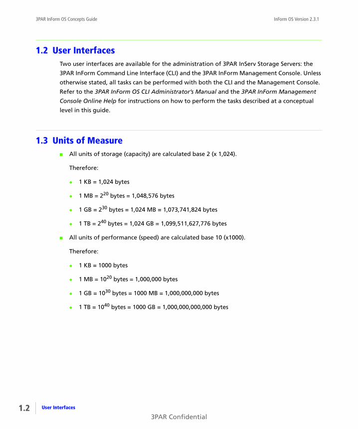
1.3 Units of Measure■ All units of storage (capacity) are calculated base 2 (x 1,024).
Therefore:
◆ 1 KB = 1,024 bytes
◆ 1 MB = 220 bytes = 1,048,576 bytes
◆ 1 GB = 230 bytes = 1,024 MB = 1,073,741,824 bytes
◆ 1 TB = 240 bytes = 1,024 GB = 1,099,511,627,776 bytes
■ All units of performance (speed) are calculated base 10 (x1000).
Therefore:
◆ 1 KB = 1000 bytes
◆ 1 MB = 1020 bytes = 1,000,000 bytes
◆ 1 GB = 1030 bytes = 1000 MB = 1,000,000,000 bytes
◆ 1 TB = 1040 bytes = 1000 GB = 1,000,000,000,000 bytes
User Interfaces
3PAR Confidential

InForm OS Version 2.3.1 3PAR InForm OS Concepts Guide
1.4 Related DocumentationThe following documents also provide information related to InServ Storage Servers and the
InForm Operating System:
Table 1-1. Related Documentation
For information about… Read the…
Using the InForm Command Line
Interface (CLI) to configure and
administer InServ Storage Servers
3PAR InForm OS CLI
Administrator’s Manual
Detailed CLI command
descriptions and usage
InForm OS Command Line
Interface Reference
Using the InForm Management
Console graphical user interface
to configure and administer
InServ Storage Servers
3PAR InForm Management
Console Online Help
Determining InServ Storage
Server hardware specifications,
installation considerations,
power requirements, networking
options, and cabling
3PAR InServ E-Class/F-Class
Storage Server Physical Planning
Manual
3PAR InServ S-Class/T-Class
Storage Server Physical Planning
Manual
Identifying storage server
components and detailed alert
information
3PAR InForm OS Messages and
Operator’s Guide
Using 3PAR Remote Copy 3PAR Remote Copy User’s Guide
Using 3PAR CIM 3PAR CIM API Programming
Reference
Using 3PAR Host Explorer 3PAR Host Explorer User’s Guide
1.3Related Documentation
3PAR Confidential
1.4
3PAR InForm OS Concepts Guide InForm OS Version 2.3.1
1.5 OrganizationThis guide is organized as follows:
■ Chapter 1, Introduction (this chapter), provides an overview of this guide, including
information on audience, related documentation, and typographical conventions.
■ Chapter 2, Overview, explains basic 3PAR concepts and terminology.
■ Chapter 3, InServ Storage Server Users, describes the different user types and their
associated privileges within the InServ storage system.
■ Chapter 4, LDAP, discusses the InForm OS LDAP client and how LDAP is used in the system.
■ Chapter 5, 3PAR Virtual Domains, explains 3PAR Virtual Domains and how it is used for
access control in the system.
■ Chapter 6, Ports and Hosts, describes how hosts and InServ Storage Server are connected.
■ Chapter 7, Chunklets, describes physical disks and chunklets.
■ Chapter 8, Logical Disks, discusses logical disks and logical disk types.
■ Chapter 9, Common Provisioning Groups, discusses how logical disks can be pooled into
groups used to provision space in virtual volumes.
■ Chapter 10, Virtual Volumes, explains virtual volumes and their role within the InServ
system.
■ Chapter 11, Reclaiming Unused Space, provides information about freeing and reclaiming
space within the InServ storage system.
■ Chapter 12, Enhanced Storage Applications, describes enhanced storage features for
managing data and improving system performance.
■ Chapter 13, 3PAR InServ Storage Server Hardware, provides an overview of the hardware
components in an InServ Storage Server.
■ Chapter 14, SNMP, describes the 3PAR SNMP agent and explains how to register a manager
with this agent.
■ Chapter 15, The 3PAR InForm CIM API, describes the 3PAR CIM API.
This guide also contains a glossary, an index, and a revision history for your reference.
Organization
3PAR Confidential

InForm OS Version 2.3.1 3PAR InForm OS Concepts Guide
1.6 Typographical ConventionsThis guide employs the following typographical conventions:
Table 1-2. Typographical Conventions
Typeface Meaning Example
ABCDabcd Used for dialog
elements such as
titles, button
labels, and other
screen elements.
When prompted, click Finish to
complete the installation.
ABCDabcd Used for paths,
filenames, and
screen output.
Open the file
\console\windows\setup.exe
ABCDabcd Used to
differentiate user
input from screen
output.
# cd \opt\3par\console
<ABCDabcd> Used for variables
in filenames,
paths, and screen
output.
Modify the content string by adding
the -P <variable> option after -jar inform.jar
<zABCDabcd> Used for variables
in user input.
#.\java -jar inform.jar -P<x>
1.5Typographical Conventions
3PAR Confidential
1.6
3PAR InForm OS Concepts Guide InForm OS Version 2.3.1
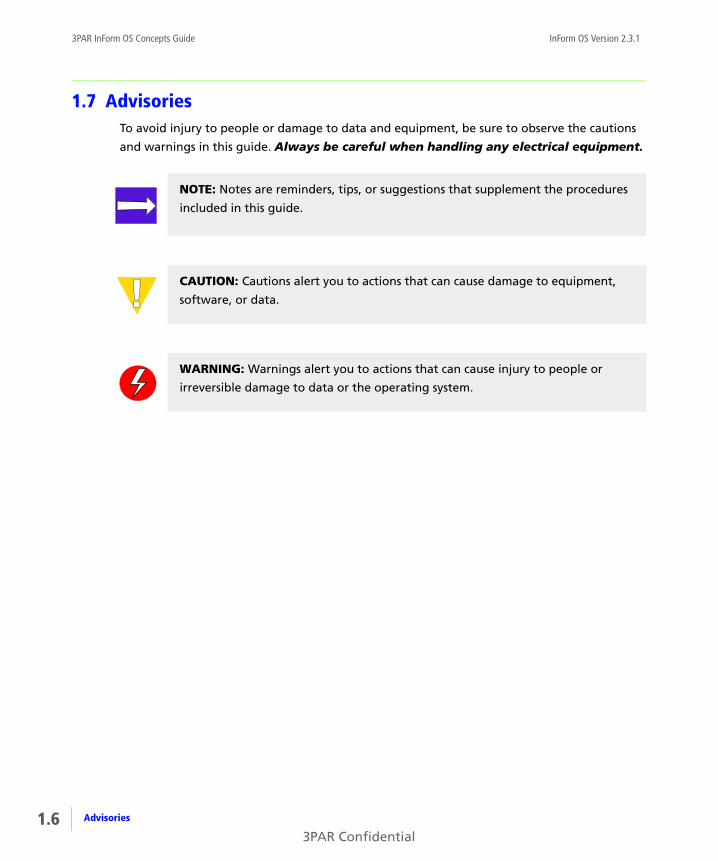
1.7 AdvisoriesTo avoid injury to people or damage to data and equipment, be sure to observe the cautions
and warnings in this guide. Always be careful when handling any electrical equipment.
NOTE: Notes are reminders, tips, or suggestions that supplement the procedures
included in this guide.
CAUTION: Cautions alert you to actions that can cause damage to equipment,
software, or data.
WARNING: Warnings alert you to actions that can cause injury to people or
irreversible damage to data or the operating system.
Advisories
3PAR Confidential

InForm OS Version 2.3.1 3PAR InForm OS Concepts Guide
2Overview
In this chapter
2.1 3PAR Storage Concepts and Terminology 2.2
2.1.1 Physical Disks 2.4
2.1.2 Chunklets 2.4
2.1.3 Logical Disks 2.4
2.1.4 Common Provisioning Groups 2.4
2.1.5 Virtual Volumes 2.5
2.2 3PAR InForm Software 2.7
2.2.1 InForm Software Suite 2.7
2.2.2 Optional Software Features 2.8
2.2.3 Host-Based Software 2.10
This chapter provides an overview of 3PAR storage concepts and discusses optional system
features, products, and solutions.
2.1Overview
3PAR Confidential

2.2
3PAR InForm OS Concepts Guide InForm OS Version 2.3.1
2.1 3PAR Storage Concepts and Terminology3PAR InServ Storage Servers include both the hardware components that physically store your
data, and the software applications that manage your data. For more information about
InServ Storage Server hardware platforms, see 3PAR InServ Storage Server Hardware. For more
information about InServ Storage Server software applications and features, see 3PAR InForm
Software.
The 3PAR InServ Storage Server is comprised of the following logical data layers:
■ Physical Disks
■ Chunklets
■ Logical Disks
■ Common Provisioning Groups
■ Virtual Volumes
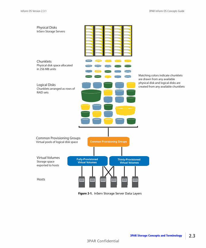
The relationship between the InServ Storage Server data layers is illustrated in Figure 2-1. Each
layer is created from elements of the layer above. Chunklets are drawn from physical disks,
logical disks are created from groups of chunklets, Common Provisioning Groups (CPGs) are
groups of logical disks, and virtual volumes use storage space provided by CPGs. The virtual
volumes are exported to hosts and are the only data layer visible to hosts.
3PAR Storage Concepts and Terminology
3PAR Confidential
InForm OS Version 2.3.1 3PAR InForm OS Concepts Guide
Figure 2-1. InServ Storage Server Data Layers
Hosts
Physical DisksInServ Storage Servers
ChunkletsPhysical disk space allocatedin 256 MB units
Logical DisksChunklets arranged as rows ofRAID sets
Virtual VolumesStorage spaceexported to hosts
Matching colors indicate chunklets are drawn from any available physical disk and logical disks arecreated from any available chunklets
Common Provisioning Groups
Fully-ProvisionedVirtual Volumes
Thinly-Provisioned Virtual Volumes
Common Provisioning GroupsVirtual pools of logical disk space
2.33PAR Storage Concepts and Terminology
3PAR Confidential

2.4
3PAR InForm OS Concepts Guide InForm OS Version 2.3.1
2.1.1 Physical Disks
A physical disk is a hard drive mounted on a drive magazine located in a 3PAR InServ Storage
Server drive cage. For more information about physical disks and the 3PAR InServ Storage
Server hardware platforms, see Chapter 13, 3PAR InServ Storage Server Hardware.
2.1.2 Chunklets
Physical disks are divided into chunklets. Each chunklet occupies 256 MB of contiguous space
on a physical disk. Chunklets are automatically created by the 3PAR InForm® Operating System
and they are used to create logical disks. A chunklet is assigned to only one logical disk. For
more information about chunklets, see Chapter 7, Chunklets.
2.1.3 Logical Disks
A logical disk is a collection of physical disk chunklets arranged as rows of RAID sets. Each RAID
set is made up of chunklets from different physical disks. Logical disks are pooled together in
Common Provisioning Groups (CPGs) which allocate space to virtual volumes. The underlying
logical disks are automatically created by the InForm OS when you create CPGs. The RAID type,
space allocation, growth increments and other logical disk parameters can be set when you
create a CPG or modified later. 3PAR storage servers support the following RAID types:
■ RAID 0
■ RAID 10 (RAID 1)
■ RAID 50 (RAID 5)
■ RAID Multi-Parity (MP) or RAID 6
For a detailed discussion of logical disks and RAID types, see Chapter 8, Logical Disks.
2.1.4 Common Provisioning Groups
A Common Provisioning Group (CPG) is a virtual pool of logical disks that allocates space to
virtual volumes on demand. A CPG allows up to 4,095 virtual volumes to share the CPG's
resources. You can create fully-provisioned virtual volumes and Thinly-Provisioned Virtual
Volumes (TPVVs) that draw space from a CPG's logical disk pool. For more information about
CPGs, see Chapter 9, Common Provisioning Groups.
3PAR Storage Concepts and Terminology
3PAR Confidential

InForm OS Version 2.3.1 3PAR InForm OS Concepts Guide
2.1.5 Virtual Volumes
Virtual volumes draw their resources from Common Provisioning Groups (CPGs), and volumes
are exported as Logical Unit Numbers (LUNs) to hosts. Virtual volumes are the only data layer
visible to the hosts. You can create physical copies or virtual copy snapshots of virtual volumes
that remain available if the original base volume becomes unavailable. Before creating virtual
volumes, you must first create CPGs to allocate space to the virtual volumes. For more
information about virtual volumes, see Chapter 10, Virtual Volumes.
2.1.5.1 Fully-Provisioned Virtual Volumes
A fully-provisioned virtual volume is a volume that uses logical disks that belong to a logical
disk pool known as a Common Provisioning Group (CPG). Unlike Thinly-Provisioned Virtual
Volumes (TPVVs), fully-provisioned virtual volumes have a set amount of user space that is
allocated for user data. The fully-provisioned volume size is fixed, and the size limit is 16 TB.
For more information about fully-provisioned virtual volumes, Fully-Provisioned Virtual
Volumes on page 10.3.
2.1.5.2 Thinly-Provisioned Virtual Volumes
A Thinly-Provisioned Virtual Volume (TPVVs) is a volume that uses logical disks that belong to a
logical disk pool known as a Common Provisioning Group (CPG). TPVVs associated with the
same CPG draw space from that pool as needed, allocating space on demand in small
increments beginning with 256 MB for each controller node. As the volumes that draw space
from the CPG require additional storage, the InForm OS automatically creates additional
logical disks and adds them to the pool until the CPG reaches the user-defined growth limit
which restricts the CPG’s maximum size. The TPVV volume size limit is 16 TB. For more
information about TPVVs, see Thinly-Provisioned Virtual Volumes on page 10.4.
NOTE: Creating Thinly-Provisioned Virtual Volumes (TPVVs) requires the 3PAR
Thin Provisioning license. For more information, see 3PAR InForm Software on
page 2.7.
2.53PAR Storage Concepts and Terminology
3PAR Confidential

2.6
3PAR InForm OS Concepts Guide InForm OS Version 2.3.1
2.1.5.3 Physical Copies
A physical copy duplicates all the data from a base volume to a destination volume. The base
volume is the original volume that is copied to the destination volume. The physical copy on
the destination volume becomes available if the original base volume becomes unavailable.
Unlike a virtual copy or snapshot, a physical copy maintains the performance of the base
virtual volume.
A physical copy can only be created from a base volume with enough free space to
accommodate writes to that volume during the physical copy operation. In addition, the
destination volume must have a user space size at least as large as the user space of the base
volume being copied, and must not be exported.
For additional information on physical copies, see Physical Copies on page 10.6.
2.1.5.4 Virtual Copy Snapshots
A snapshot is a virtual copy of a base volume. The base volume is the original volume that is
copied. Unlike a physical copy which is a duplicate of an entire volume, a virtual copy only
records changes to the base volume. This allows an earlier state of the original virtual volume
to be recreated by starting with its current state and rolling back all the changes that have
been made since the virtual copy was created.
You can make snapshots of: fully-provisioned virtual volumes, TPVVs, physical copies, or
another virtual copy snapshot. Snapshots are created using copy-on-write techniques available
only with the 3PAR Virtual Copy license. Thousands of snapshots of each virtual volume can be
created assuming that there is sufficient storage space available. For additional information on
virtual copies, see Virtual Copy Snapshots on page 10.7.
NOTE: With a 3PAR Remote Copy license, physical copies can be copied from one
InServ Storage Server to another using 3PAR Remote Copy. For additional
information, see the 3PAR Remote Copy User’s Guide.
NOTE: Creating virtual copies requires the 3PAR Virtual Copy license.For more
information, see 3PAR InForm Software on page 2.7.
3PAR Storage Concepts and Terminology
3PAR Confidential

InForm OS Version 2.3.1 3PAR InForm OS Concepts Guide
2.1.5.4.1 Exporting Virtual Volumes
For a host to see a virtual volume, the volume must be exported as a Logical Unit Number
(LUN). Volumes are exported by creating Virtual Volume-LUN pairings (VLUNs) on the InServ
Storage Server. When you create VLUNs the system produces both VLUN templates that
establish export rules, and active VLUNs that the host sees as a LUN or attached disk device. For
more information about active VLUNs, VLUN templates, and VLUN template types, see
Exporting Virtual Volumes.
2.2 3PAR InForm SoftwareIn addition to the 3PAR InForm Software Suite, 3PAR offers separately licensed optional
features and a set of host-based software applications. You can use the 3PAR InForm
Command Line Interface (CLI) and the 3PAR InForm Management Console to view the licenses
currently enabled on your InServ Storage Servers.
2.2.1 InForm Software Suite
All 3PAR InServ Storage Servers include the 3PAR InForm Software Suite. The InForm Software
Suite is the core set of storage management software.
The 3PAR InForm Software Suite includes:
■ 3PAR InForm Operating System, independent instances of the operating system running
on each controller node.
■ 3PAR InForm Command Line Interface, command line user interface for monitoring,
managing, and configuring 3PAR InServ Storage Servers.
■ 3PAR InForm Management Console, graphical user interface for monitoring, managing,
and configuring 3PAR InServ Storage Servers.
■ Access Guard, provides volume security at logical and physical levels by enabling you to
secure hosts and ports to specific virtual volumes.
■ 3PAR Autonomic Groups, allow domains, hosts, and volumes to be grouped into a set
that is managed as a single object. Autonomic groups also allow for easy updates when
new hosts are added or new volumes are provisioned. If you add a new host to the set,
NOTE: To learn about adding optional products and features to enhance your
3PAR InServ Storage Servers, contact your local service provider.
2.73PAR InForm Software
3PAR Confidential

2.8
3PAR InForm OS Concepts Guide InForm OS Version 2.3.1
volumes from the volume set are autonomically provisioned to the new host without any
administrative intervention. If you add a new volume or a new domain to a set, the volume
or domain inherits all the privileges of the set.
■ 3PAR Persistent Cache, allows InServ Storage Servers to maintain a high level of
performance and availability during node failure conditions, and during hardware and
software upgrades. This feature allows the host to continue to write data and receive
acknowledgments from the storage server if the backup node is unavailable. Persistent
Cache automatically creates multiple backup nodes for logical disks that have the same
owner.
■ 3PAR mySnapshot, is a copy utility designed for non-storage professionals such as
database administrators, software developers, and test engineers to safely and easily copy
and provision their own test data. With mySnapshot, developers have instant access to test
data, thus eliminating the time required to request, justify, and receive these copies from
the storage administrator. To learn more about the mySnapshot utility, see Chapter 12,
Enhanced Storage Applications.
2.2.2 Optional Software Features
Optional 3PAR software features may not currently be enabled on your system because they
require additional licenses and may require separate installations. When features are not
available on your system because they are not licensed for use, screens and functionality
relating to those features may appear grayed-out or be otherwise inaccessible in the InForm
Management Console and InForm CLI.
InServ Storage Servers may use the following optional software features:
■ 3PAR Virtual Domains are used for access control. Virtual Domains allow you to limit the
privileges of users to only subsets of volumes and hosts in an InServ Storage Server and
ensures that virtual volumes associated with a specific domain are not exported to hosts
outside of that domain. To learn more about domains, see Chapter 5, 3PAR Virtual
Domains.
■ 3PAR Thin Provisioning allows you to allocate virtual volumes to application servers yet
provision only a fraction of the physical storage behind these volumes. By enabling a true
capacity-on-demand model, a storage administrator can use 3PAR Thin Provisioning to
create Thinly-Provisioned Virtual Volumes (TPVVs) that maximize asset use. To learn more
about TPVVs, see Chapter 10, Virtual Volumes.
3PAR InForm Software
3PAR Confidential

InForm OS Version 2.3.1 3PAR InForm OS Concepts Guide
■ 3PAR Thin Conversion converts a fully-provisioned volume to a Thinly-Provisioned Virtual
Volume (TPVV). Virtual volumes with large amounts of allocated but unused space are
converted to TPVVs that are much smaller than the original volume. To use the Thin
Conversion feature you must have an InServ F-Class or T-Class Storage Server, a 3PAR Thin
Provisioning license, and a 3PAR Thin Conversion license. To learn more about 3PAR Thin
Conversion, see Chapter 12, Enhanced Storage Applications.
■ 3PAR Thin Persistence keeps InServ Thinly-Provisioned Virtual Volumes (TPVVs) small by
detecting pages of zeros during data transfers and not allocating space for the zeros. This
feature works in real-time and analyzes the data before it is written to the destination
TPVV. To use the Thin Persistence feature you must have an InServ F-Class or T-Class Storage
Server, a 3PAR Thin Provisioning license, a 3PAR Thin Conversion license, and a 3PAR Thin
Persistence license. To learn more about 3PAR Thin Persistence, see Chapter 12, Enhanced
Storage Applications.
■ 3PAR Thin Copy Reclamation reclaims space when snapshots are deleted from an InServ
Storage Server. As snapshots are deleted, the snapshot space is reclaimed from a TPVV or
fully-provisioned virtual volume and returned to the CPG for reuse by other volumes. To
learn more about 3PAR Thin Copy Reclamation, see Chapter 12, Enhanced Storage
Applications.
■ 3PAR Virtual Copy allows you to take instant virtual copy snapshots of existing volumes. It
uses copy-on-write technology so that virtual copies consume minimal capacity. Virtual
copies are presentable to any host with read and write capabilities. In addition, virtual
copies can be made from other virtual copies, providing endless flexibility for test, backup,
and business-intelligence applications. To learn more about virtual copies, see Virtual Copy
Snapshots on page 10.7.
■ 3PAR Remote Copy is a host-independent, array-based data mirroring solution that
enables affordable data distribution and disaster recovery for applications. With this
optional utility, you can copy virtual volumes from one InServ Storage Server to a second
InServ Storage Server. 3PAR Remote Copy currently requires the use of the InForm CLI. For
more information about the 3PAR Remote Copy application, see the 3PAR Remote Copy
User’s Guide.
■ 3PAR Dynamic Optimization allows you to improve the performance of virtual volumes
without interrupting access. Use this feature to avoid over provisioning for peak system
usage by optimizing the layout of your virtual volumes. With 3PAR Dynamic Optimization
you can change virtual volume parameters, RAID levels, set sizes, and disk filters by
associating the virtual volume with a new CPG. To learn more about 3PAR Dynamic
Optimization, see Chapter 12, Enhanced Storage Applications.
2.93PAR InForm Software
3PAR Confidential

2.10
3PAR InForm OS Concepts Guide InForm OS Version 2.3.1
■ 3PAR System Tuner improves performance by identifying over-used physical disks, and
performing load balancing on those disks without interrupting access. To learn more about
the 3PAR System Tuner, see Chapter 12, Enhanced Storage Applications.
■ 3PAR Virtual Lock enforces the retention period of any volume or copy of a volume. To
learn more about Virtual Lock, see Chapter 12, Enhanced Storage Applications.
2.2.3 Host-Based Software
3PAR host-based software applications are tightly integrated with the host environment to
improve performance and integrate host functionality with InServ Storage Servers. Some of
these applications require additional licenses, contact your local service provider to learn more
about any of the 3PAR host-based software applications.
■ 3PAR Recovery Manager for Microsoft Exchange is a separately purchased and
licensed application that is specifically designed to integrate with Microsoft VSS to provide
a simple, efficient and highly scalable solution for backup and recovery of Microsoft
Exchange environments. 3PAR Recovery Manager intelligently creates, manages, and
presents time-consistent snapshot images of Microsoft Exchange databases for non-
disruptive backup, rapid application recovery, and data sharing.
■ 3PAR Recovery Manager for SQL Server is a separately purchased and licensed
application that is specifically designed to integrate with Microsoft VSS to provide a simple,
efficient and highly scalable solution for backup and recovery of SQL Server environments.
3PAR Recovery Manager intelligently creates, manages, and presents time-consistent
snapshot images of SQL Server databases for non-disruptive backup, rapid application
recovery, and data sharing.
■ 3PAR VSS Provider for Microsoft Windows is a server application bundled with
Recovery Manager for Microsoft Exchange and SQL Server.
VSS coordinates the actions of:
◆ Database readers like the 3PAR Recovery Manager backup application.
◆ Database writers like Microsoft Exchange and SQL Server.
◆ Providers that create shadow copies.
3PAR InForm Software
3PAR Confidential

InForm OS Version 2.3.1 3PAR InForm OS Concepts Guide
■ 3PAR Recovery Manager for Oracle on Solaris and Red Hat Linux is a separately
purchased and licensed application that provides a simple, efficient and highly scalable
solution for backup and recovery of Oracle databases. 3PAR Recovery Manager intelligently
creates, manages, and presents time-consistent snapshot images of Oracle databases for
non-disruptive backup, rapid application recovery, and data sharing.
■ 3PAR Multipath I/O (MPIO) for IBM AIX is a separately purchased and licensed
application that enables the host to use more than one physical I/O path to the InServ
Storage Server. Multipathing improves system reliability and availability by providing fault
tolerance and load balancing of I/O traffic.
■ 3PAR Multipath I/O (MPIO) for Microsoft Windows is a separately purchased and
licensed application that enables the host to use more than one physical I/O path to the
InServ Storage Server. Multipathing improves system reliability and availability by providing
fault tolerance and load balancing of I/O traffic.
■ 3PAR Host Explorer agents are programs that run on hosts connected InServ Storage
Servers. When a host is created on the InServ Storage Server, unassigned WWNs or iSCSI
names are presented to the storage server. Without the Host Explorer agents running on
the attached hosts, the storage server is unable to determine which host the WWN or iSCSI
names belongs to and you must manually assign each WWN or iSCSI name to a host. With
Host Explorer agents running, the InServ Storage Server automatically groups WWNs or
iSCSI names for the host together, assisting with creating the host. The Host Explorer agent
runs as a service on Windows and as a daemon on Linux and Solaris operating systems. No
license is required to use the 3PAR Host Explorer agent. To learn more about Host Explorer
agents, see Chapter 6, Ports and Hosts.
■ 3PAR System Reporter is an application that enables you to monitor performance, create
charge back reports, and plan storage resources for InServ Storage Servers using either a
standard Web browser or the 3PAR System Reporter Excel client. No license is required to
use the 3PAR System Reporter.
2.113PAR InForm Software
3PAR Confidential

2.12
3PAR InForm OS Concepts Guide InForm OS Version 2.3.1
3PAR InForm Software
3PAR Confidential
InForm OS Version 2.3.1 3PAR InForm OS Concepts Guide
3InServ Storage Server Users
In this chapter
3.1 Overview 3.1
3.2 Local Users 3.2
3.3 Domain Users 3.3
3.4 LDAP Users 3.4
The purpose of this chapter is to provide an overview of different types of InServ Storage
Server users.
3.1 OverviewA user account is required to access an InServ Storage Server. The first user account must be set
up on the node itself. User accounts are created by the system administrator and each user is
assigned a user class permitting varying levels of accessibility within the system.
There are three types of users:
■ Local users.
■ Domain users.
■ LDAP users.
3.1InServ Storage Server Users
3PAR Confidential

3.2
3PAR InForm OS Concepts Guide InForm OS Version 2.3.1
Creating local users and assigning system accessibility can be performed with both the 3PAR
InForm Command Line Interface (CLI) and the 3PAR InForm Management Console. Refer to the
3PAR InForm OS CLI Administrator’s Manual and the 3PAR InForm Management Console
Online Help for instructions on how to perform these tasks.
3.2 Local UsersLocal users are users created on the system and access the system using the InForm CLI or
InForm Management Console. Each user is assigned one of four user classes during creation,
which allow varying levels of accessibility in the system. These classes are described in
Table 3-1.
The information used to authenticate and authorize a local user is stored directly on the InServ
Storage Server where that user was created.
For instructions on creating a local user, refer to the InForm OS CLI Administrator’s Manual and
the InForm OS Management Console Online Help.
Table 3-1. User Classes
User Class Accessibility
Browse Allows read-only accessibility.
Edit Allows access to most system functions, such as
creating and editing virtual volumes.
Super Allows access to all system functions.
Service Allows access to limited system functions to
service the storage server; allows limited access to
user information and user group resources.
Local Users
3PAR Confidential
InForm OS Version 2.3.1 3PAR InForm OS Concepts Guide
3.3 Domain Users
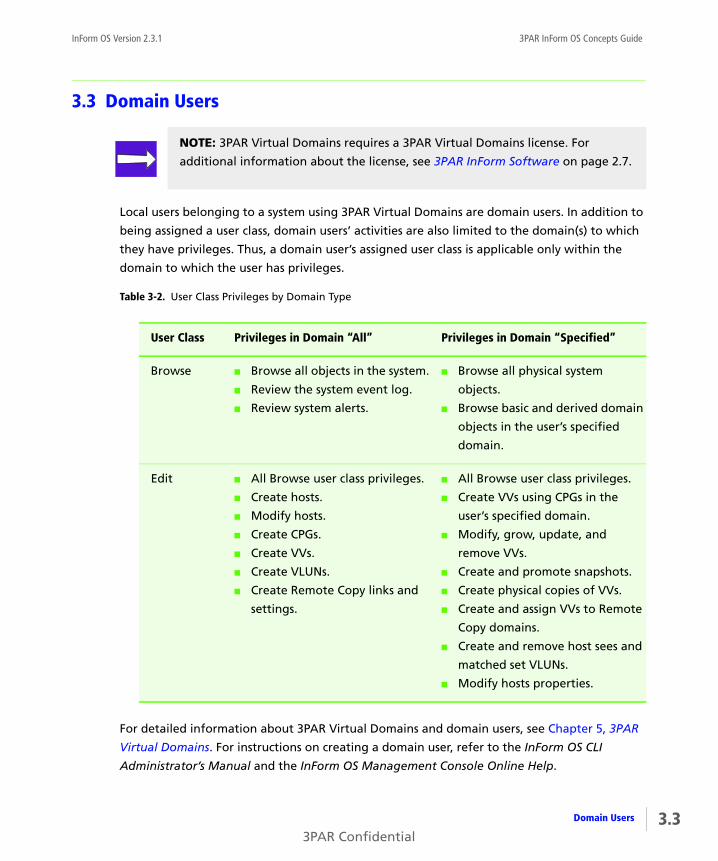
Local users belonging to a system using 3PAR Virtual Domains are domain users. In addition to
being assigned a user class, domain users’ activities are also limited to the domain(s) to which
they have privileges. Thus, a domain user’s assigned user class is applicable only within the
domain to which the user has privileges.
For detailed information about 3PAR Virtual Domains and domain users, see Chapter 5, 3PAR
Virtual Domains. For instructions on creating a domain user, refer to the InForm OS CLI
Administrator’s Manual and the InForm OS Management Console Online Help.
NOTE: 3PAR Virtual Domains requires a 3PAR Virtual Domains license. For
additional information about the license, see 3PAR InForm Software on page 2.7.
Table 3-2. User Class Privileges by Domain Type
User Class Privileges in Domain “All” Privileges in Domain “Specified”
Browse ■ Browse all objects in the system.
■ Review the system event log.
■ Review system alerts.
■ Browse all physical system
objects.
■ Browse basic and derived domain
objects in the user’s specified
domain.
Edit ■ All Browse user class privileges.
■ Create hosts.
■ Modify hosts.
■ Create CPGs.
■ Create VVs.
■ Create VLUNs.
■ Create Remote Copy links and
settings.
■ All Browse user class privileges.
■ Create VVs using CPGs in the
user’s specified domain.
■ Modify, grow, update, and
remove VVs.
■ Create and promote snapshots.
■ Create physical copies of VVs.
■ Create and assign VVs to Remote
Copy domains.
■ Create and remove host sees and
matched set VLUNs.
■ Modify hosts properties.
3.3Domain Users
3PAR Confidential

3.4
3PAR InForm OS Concepts Guide InForm OS Version 2.3.1
3.4 LDAP UsersWhereas local users are authenticated and authorized directly on the InServ Storage Server,
LDAP users are authenticated and authorized using information from an LDAP server. If
multiple InServ Storage Servers are configured to use the same LDAP server in the same way, a
user that can access one of the InServ servers can access all of them with the same privileges.
LDAP users’ privileges within the system are tied to the groups to which the users belong. This
is a significant difference from local users in that privileges are associated with a group rather
than an individual. Group privileges are identical to local user’s user classes as described in
Local Users on page 3.2.
For detailed information about LDAP users and LDAP connections, see Chapter 4, LDAP. For
instructions on setting up an LDAP connection, refer to the InForm OS CLI Administrator’s
Manual.
LDAP Users
3PAR Confidential

InForm OS Version 2.3.1 3PAR InForm OS Concepts Guide
4LDAP
In this chapter
4.1 Overview 4.1
4.2 LDAP Users 4.3
4.3 LDAP Server Data Organization 4.4
4.4 LDAP and Domains 4.4
4.5 LDAP Authentication and Authorization 4.5
The purpose of this chapter is to provide information about using LDAP with InServ Storage
Servers.
4.1 OverviewThe Lightweight Directory Access Protocol (LDAP) is a standard protocol for communication
between LDAP clients and LDAP directory servers. Data is stored as a directory hierarchy by the
server and clients add, modify, search, or remove the data. The data can be organized using
standard schemas understood by clients and servers from different vendors or by an
application-specific schema used only by a particular vendor or application.
The InForm OS contains an LDAP client that can be configured to use an LDAP server for
authentication and authorization of InServ Storage Server users. In an environment where
4.1LDAP
3PAR Confidential

4.2
3PAR InForm OS Concepts Guide InForm OS Version 2.3.1
there are multiple InServ servers configured to use the same LDAP server in the same way, a
single user with access to one InServ server can access all of the environment’s InServ servers
with the same privileges.
Accessing objects on InServ servers configured to use 3PAR Virtual Domains requires privileges
in the domain in which those objects reside. The configuration of domains may differ from one
InServ system installation to the next. This results in differing levels of privileges over objects
based on mapping between the LDAP configuration and the individual InServ server’s domain
configuration.
The InForm OS LDAP client is designed to work with various LDAP servers and schemas for data
organization. However, only use with the Active Directory LDAP directory implementation is
currently supported.
Configuring the InForm OS to use LDAP can only be performed with the 3PAR InForm
Command Line Interface (CLI). Refer to the 3PAR InForm OS CLI Administrator’s Manual for
instructions on how to perform these tasks.
4.1.1 Active Directory
Active Directory is an implementation of LDAP directory services by Microsoft for use in
Windows environments. An Active Directory server is both an LDAP and Kerberos server. When
set up for SASL binding (see SASL Binding on page 4.6), the Active Directory server and
Kerberos server are used for both authorization and authentication of users.
NOTE: At the current time, the OpenLDAP directory implementation is also
available, however, on a limited basis. Check with your local 3PAR service
representative for updates on availability.
NOTE: All LDAP related tasks are performed with the 3PAR InForm Command
Line Interface (CLI).
Overview
3PAR Confidential

InForm OS Version 2.3.1 3PAR InForm OS Concepts Guide
4.1.2 OpenLDAP
OpenLDAP is an open source implementation of LDAP directory services developed by the
OpenLDAP Project. OpenLDAP includes a server, client library, and tools that are available for a
wide variety of operating systems. Different schemas can be used for user and group
information with OpenLDAP. For example, the Posix schema is typically used for user and
group information in Linux/Unix systems.
4.2 LDAP UsersUser’s created with the InForm CLI who access the InServ Storage Server using InForm CLI
clients, or with SSH, are authenticated and authorized directly on the InServ Storage Server.
These users are referred to as local users. An LDAP user is similar to a local user, however an
LDAP user is authenticated and authorized using information from an LDAP server.
During authentication, if a user name is not recognized as a local user, that user’s name and
password are checked on the LDAP server. Users existing as both a local user and LDAP use who
share the same user name, are authenticated by the InServ Storage Server. That is, the local
user’s authentication data takes precedence over the user’s LDAP authentication data. User
names not associated with local user names are authenticated using LDAP data.
Additionally for local users, during authentication, the password supplied by the user must
match the password assigned when that user was initially created or modified. The privileges
assigned to the user during authorization are the same privileges associated with the user class
assigned when that user was initially created or modified. See Chapter 3, InServ Storage Server
Users for additional information about user types and user classes. The LDAP server is not used
for any additional password checking or assigning of privileges.
LDAP users can access the InServ server using the same methods as a local users, although some
user account creation and modification operations are unavailable. LDAP users access is limited
to the system they were logged into when they saved their password. For instructions on using
LDAP with the InServ Storage Server, refer to the 3PAR InForm OS CLI Administrator’s Manual.
Another key difference between local users and LDAP users is that a local user’s privileges
within the InServ system are assigned on a case-by-case basis. An LDAP user’s privileges are
dependent on that user’s group association. In other words, groups are assigned specific
privileges within the InServ system and an individual LDAP user’s privileges are dependent
upon group membership.
4.3LDAP Users
3PAR Confidential
4.4
3PAR InForm OS Concepts Guide InForm OS Version 2.3.1
4.3 LDAP Server Data OrganizationLDAP server data consists of user information, which includes the user’s group associations.
Data can be previously existing data used for user account information, or can be data created
for specific use with InServ Storage Servers. Data on the LDAP server can be organized in two
different ways:
■ As a list of groups associated with each user.
■ As a list of users associated with each group.
The form in which data is organized is dependent on the type of LDAP server used and the
tools used to maintain the data. Programs such as ldp.exe, which is a downloadable
Windows Support Tool available from Microsoft, and ldapsearch, which is available for many
Unix and Linux systems, can be used to view data entries in the LDAP server. This can be useful
when configuring the InForm OS LDAP client with your LDAP server as discussed in Chapter 4,
Managing User Accounts and Connections, in the InForm OS CLI Administrator’s Manual.
4.4 LDAP and DomainsLDAP is also available for InServ Storage Servers using 3PAR Virtual Domains for access control.
As discussed in Chapter 5, 3PAR Virtual Domains, the Domains facility enables finer grain
privileges over system objects such as volumes and hosts. Accessing objects on InServ servers
configured to use 3PAR Virtual Domains requires privileges in the domain in which those
objects reside. Because the configuration of Domains can differ within an InServ Storage
Server, or from one server to another (in configurations with multiple servers), a user can have
differing privileges between domains in a single system, or across multiple systems.
As discussed earlier in LDAP Users on page 4.3, LDAP users must follow a process of
authentication and authorization in order to gain access to the InServ system. With Domains in
use, in addition to authentication with the InServ Storage Server, LDAP users must also be
authorized to access domains set up within the system. For additional information, see LDAP
Authentication and Authorization on page 4.5.
For instructions on setting up LDAP users on systems using Domains, see Chapter 4, Managing
User Accounts and Connections in the InForm OS CLI Administrator’s Manual.
LDAP Server Data Organization
3PAR Confidential

InForm OS Version 2.3.1 3PAR InForm OS Concepts Guide
4.5 LDAP Authentication and AuthorizationAs stated earlier, the user’s user name is first checked against the authentication data stored on
the local InServ Storage Server. If the user’s name is not found, the LDAP authentication and
authorization process proceeds as follows:
■ The user’s user name and password are used to authenticate with the LDAP server.
■ The user’s group memberships are determined with the data on the LDAP server.
■ A list of groups is compared against mapping rules that specify each group’s associated
privilege level.
■ If 3PAR Virtual Domains is in use, the user’s group is mapped to a domain.
■ The user is assigned a privilege level within the InServ system; or if using Domains, within a
domain, or domains, in the InServ system.
4.5.1 Authentication
Users are authenticated with the LDAP server using a bind operation. The bind operation
simply authenticates the InForm OS LDAP client to the LDAP server. This authentication process
is required for all systems using LDAP, including systems using Domains. Several binding
mechanisms are supported by the InForm OS LDAP client.
4.5.1.1 Simple Binding
With simple binding, the user’s user name and password are sent to the LDAP server in plain
text and the LDAP server determines if the submitted password is correct. Simple binding is not
recommended unless a secure connection to the LDAP server is established with Secure Sockets
Layer (SSL) or Transport Layer Security (TLS).
NOTE: 3PAR Virtual Domains requires a 3PAR Virtual Domains license. For
additional information about the license, see Optional Software Features on
page 2.8.
4.5LDAP Authentication and Authorization
3PAR Confidential

4.6
3PAR InForm OS Concepts Guide InForm OS Version 2.3.1
4.5.1.2 SASL Binding
In addition to simple binding, the InForm OS LDAP client also supports the PLAIN, DIGEST-MD5,
and GSSAPI SASL binding mechanisms. Generally, DIGEST-MD5 and GSSAPI are more secure
methods of authentication as user passwords are not sent to the LDAP server.
■ The PLAIN mechanism is similar to simple binding where the user’s user name and password
are sent directly to the LDAP server for authentication. As with simple binding, the PLAIN
mechanism should only be used if there is a secure connection (SSL or TLS) to the LDAP
server.
■ The GSSAPI mechanism obtains a ticket from the Kerberos server which validates the user’s
identity. That ticket is then sent to the LDAP server for authentication.
■ With the DIGEST-MD5 mechanism, the LDAP server sends the InForm OS LDAP client one-
time data that is encrypted by the client and returned to the server in such a way that the
client proves it knows the user's password without having to send the user's password.
4.5.2 Authorization
Once an LDAP user has been authenticated, the next stage is authorization. The authorization
process determines what a user is allowed to do within the InServ system.
As discussed in LDAP Users on page 4.3, an LDAP user’s privileges are tied to that user’s group
membership, and a user can belong to multiple groups. Each group has an assigned privilege
level allowing super, service, edit, or browse privileges within the system (see Chapter 3, InServ
Storage Server Users for information about user privileges). The InForm OS LDAP client
performs group-to-privilege mapping using the following four mapping parameters:
■ super-map
■ service-map
■ edit-map
■ browse-map
Each group to which a user is a member is compared against the mapping parameters.
Mapping occurs sequentially with a group first compared to the super-map parameter. If no
NOTE: The SASL mechanism you can use is dependent on your LDAP server
configuration.
LDAP Authentication and Authorization
3PAR Confidential

InForm OS Version 2.3.1 3PAR InForm OS Concepts Guide
match is made, the group is then compared with the service-map parameter, and so on. For
example, if a match is made for group A with the super-map parameter, the user belonging
to group A is authorized with super level privileges for the system.
With this process, a user can be authenticated, but not authorized if no group membership
exists. In this case, the user is subsequently denied access to the system.
4.5.3 Authorization on Systems Using 3PAR Virtual Domains
As discussed in Authorization on page 4.6, a user’s group association determines that user’s
privileges within the system. On systems using 3PAR Virtual Domains, this process is taken one
step further where the user’s groups are mapped to system domains. Therefore, the user’s
privilege level within a specific group is carried over to the domain(s) mapped to that group.
For instructions on authorizing LDAP users on systems using Domains, see Chapter 4, Managing
User Accounts and Connections in the InForm OS CLI Administrator’s Manual.
Figure 4-1 illustrates the group-to-domain mapping relationship as follows:
■ LDAP User 1 has membership to Group B.
■ Group-to-privilege mapping determines that Group B has edit level privileges.
■ Group-to-domain mapping establishes a match between Group B and Domain A.
■ LDAP User 1 has edit privileges over all objects in Domain A.
Figure 4-1. Group-to-Domain Mapping Relationship
LDAP User 1Group A
Group BDomain B (D.B)
D.BObj1
D.BObj2
D.BObj3
D.BObj4
D.AObj1
D.AObj2
D.AObj3
D.AObj4
Domain A (D.A)
Edit-Map
4.7LDAP Authentication and Authorization
3PAR Confidential

4.8
3PAR InForm OS Concepts Guide InForm OS Version 2.3.1
LDAP Authentication and Authorization
3PAR Confidential

InForm OS Version 2.3.1 3PAR InForm OS Concepts Guide
53PAR Virtual Domains
In this chapter
5.1 Overview 5.1
5.2 Domain Types and User Classes 5.3
5.3 Users and Domain Privileges 5.4
5.4 Object and Domain Association Rules 5.5
5.5 The Default and Current Domains 5.5
The purpose of this chapter is to explain the relationship between users and 3PAR Virtual
Domains.
5.1 OverviewWhen initially setting up the InServ Storage Server, the system administrator creates and
assigns users with varying levels of accessibility in the system. You can create, modify, and
remove a user’s access to virtual domains in the system with both the 3PAR InForm Command
Line Interface (CLI) and the 3PAR InForm Management Console. Refer to the 3PAR InForm OS
CLI Administrator’s Manual and the 3PAR InForm Management Console Online Help for
instructions on how to perform these tasks.
5.13PAR Virtual Domains
3PAR Confidential

5.2
3PAR InForm OS Concepts Guide InForm OS Version 2.3.1
In addition to the inherent security provided by this hierarchical user structure, finer grain
access control of the InServ system can optionally be achieved through the implementation of
3PAR Virtual Domains (domains).
Domains allows an administrator to create up to 1024 domains, or spaces, within an
InServ Storage Server, where each domain is dedicated to a specific application. A subset of the
InServ Storage Server users have varying privileges over the domains. The use of domains can
be useful in scenarios where a single InServ Storage Server is used to manage data from several
different independent applications (Figure 5-1).
Figure 5-1. Single Storage Server Managing Multiple Independent Applications
Each domain allows users with varying levels of accessibility to domain objects. A domain is
made of Common Provisioning Groups (CPGs), hosts, and Remote Copy groups. Domains
contain derived domain objects such as Virtual Volumes (VVs), Logical Disks (LDs), and volume
exports (VLUNs). Because objects are domain-specific, domain users cannot accidentally or
deliberately export VVs to hosts outside of their assigned domain.
NOTE: 3PAR Virtual Domains require a 3PAR Virtual Domains license. For
additional information about the license, see 3PAR InForm Software on page 2.7.
InServ
Application A(data source A)
Application B(data source B)
Application C(data source C)
StorageServer
Domain A
Domain B
Domain C
Overview
3PAR Confidential

InForm OS Version 2.3.1 3PAR InForm OS Concepts Guide
Virtual domains can be grouped into autonomic groups that can be managed as one domain.
If you have a group of domains that require the same administrative procedures, it is easier to
group those domains into an autonomic group and mange them together.
5.2 Domain Types and User ClassesWhen using domains for access control, accessibility to basic objects and derived objects is
limited by a user’s class (privilege level) and domain assignment.
5.2.1 Domain Type
The first tier of access control is the domain to which a subset of an InServ system’s objects
belong. The objects can be assigned to a specific domain, or have no domain association.
■ The no domain contains objects that do not belong to any specified domains. For
example, objects in an existing InServ system that did not previously use domains do not
belong to any domains.
■ specified domains are created by the domain administrator and contain objects specific
to that domain. Only users with privileges over that domain can work with those objects.
For example, User A in Domain A can access objects in Domain A, but not in Domain B.
Multiple specified domains can be created. Users with the super level privileges can
browse and edit objects in all domains.
5.2.2 User Class
After determining the domain type, the second tier of access control limiting user access is the
user class. In terms of domains, user class defines a user’s authority level within a domain to
access and work with basic and derived domain objects.
There are two classes of domain user, Browse and Edit (Table 5-1). System object accessibility
and domain accessibility are dependent on the user’s privilege level.
NOTE: Remote Copy requires a 3PAR Remote Copy license. For additional
information about the license, see 3PAR InForm Software on page 2.7.
5.3Domain Types and User Classes
3PAR Confidential
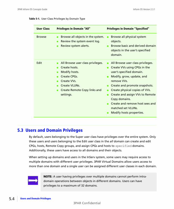
5.4
3PAR InForm OS Concepts Guide InForm OS Version 2.3.1
5.3 Users and Domain PrivilegesBy default, users belonging to the Super user class have privileges over the entire system. Only
these users and users belonging to the Edit user class in the all domain can create and edit
CPGs, hosts, Remote Copy groups, and assign CPGs and hosts to specified domains.
Additionally, these users have access to all domains and their objects.
When setting up domains and users in the InServ system, some users may require access to
multiple domains with different user privileges. 3PAR Virtual Domains allow users access to
more than one domain and a single user can be assigned different user classes in each domain.
Table 5-1. User Class Privileges by Domain Type
User Class Privileges in Domain “All” Privileges in Domain “Specified”
Browse ■ Browse all objects in the system.
■ Review the system event log.
■ Review system alerts.
■ Browse all physical system
objects.
■ Browse basic and derived domain
objects in the user’s specified
domain.
Edit ■ All Browse user class privileges.
■ Create hosts.
■ Modify hosts.
■ Create CPGs.
■ Create VVs.
■ Create VLUNs.
■ Create Remote Copy links and
settings.
■ All Browse user class privileges.
■ Create VVs using CPGs in the
user’s specified domain.
■ Modify, grow, update, and
remove VVs.
■ Create and promote snapshots.
■ Create physical copies of VVs.
■ Create and assign VVs to Remote
Copy domains.
■ Create and remove host sees and
matched set VLUNs.
■ Modify hosts properties.
NOTE: A user having privileges over multiple domains cannot perform intra-
domain operations between objects in different domains. Users can have
privileges to a maximum of 32 domains.
Users and Domain Privileges
3PAR Confidential

InForm OS Version 2.3.1 3PAR InForm OS Concepts Guide
5.4 Object and Domain Association RulesDomains contain basic objects such as CPGs, hosts, and Remote Copy groups, and derived
objects such as VVs, LDs, and VLUNs. Objects and their associations with domains must adhere
to the following rules:
■ Objects derived from a CPG inherit the domain of that CPG.
■ VVs can only be exported to hosts belonging to the VVs’ domain.
■ A VLUN inherits the domain of the VV and host from which the VLUN was exported.
5.5 The Default and Current DomainsWhen a user is initially created, the user is able access objects in all assigned domains. The user
can browse or edit objects depending on the user’s assigned user class. For example, an edit
level user assigned to Domains A and B can view and work on objects in both Domains A and B
(Figure 5-2). However, if it is apparent that a specific domain will receive the majority of
attention from a user, 3PAR Virtual Domains provides the ability for administrators to set a
default domain for that user.
Figure 5-2. Assigned Domains
An InForm CLI user’s default domain is the domain the user accesses at the start of each CLI
session. For example, if you have edit privileges to Domains A and B and your default domain
has been set to Domain A, each time you start a new CLI session you will view and work with
only objects in Domain A (Figure 5-2). The user’s default domain can be set and reset at any
time by the administrator.
User belonging toedit user class
Domain A
Domain B
ALL assigned domains’ objects viewable and operable.
5.5Object and Domain Association Rules
3PAR Confidential

5.6
3PAR InForm OS Concepts Guide InForm OS Version 2.3.1
If you are using the InForm Management Console, the user selects which domain to connect to
and there is no default domain, and no domain session. To change domains, InForm
Management Console users simply select a new domain from a menu of available domains.
The Default and Current Domains
3PAR Confidential

InForm OS Version 2.3.1 3PAR InForm OS Concepts Guide
6Ports and Hosts
In this chapter
6.1 Overview 6.2
6.2 About Ports 6.2
6.3 Port Location Formats 6.3
6.4 Port Target, Initiator, and Peer Modes 6.4
6.5 Active and Inactive Hosts 6.4
6.6 Adding and Removing Hosts 6.5
6.7 Host Personas 6.5
6.8 The Host Explorer Agent 6.8
The purpose of this chapter is to explain the interaction between ports, hosts, and host
personas.
6.1Ports and Hosts
3PAR Confidential
6.2
3PAR InForm OS Concepts Guide InForm OS Version 2.3.1
6.1 OverviewThe InServ Storage Server sees a host as a set of initiator port WWNs (World Wide Names) or
iSCSI Names. Hosts that are physically connected to ports on the InServ Storage Server are
automatically detected. The Fibre Channel port WWNs and iSCSI port iSCSI Names are
displayed by the user interfaces. You can also add new WWNs or iSCSI Names for unestablished
host paths and assign them to a host before they are physically connected. These WWNs or
iSCSI Names do not need to be associated with target ports on the storage server controller
nodes. This allows for plug-and-play functionality that avoids the need for manual
reconfiguration after connecting new hosts. For instructions on modifying InServ Storage
Server ports and host configurations, see the InForm OS CLI Administrator’s Manual and
InForm OS Management Console Online Help.
A virtual volume can be exported, or made accessible, to one or more hosts. The host sees the
exported virtual volume as a LUN connected to one or more ports. Once the virtual volume is
exported to a host, the host can send requests to the LUN. See Chapter 10, Virtual Volumes for
more information about virtual volumes and exporting virtual volumes. For instructions on
exporting virtual volumes, see the InForm OS CLI Administrator’s Manual and InForm OS
Management Console Online Help.
6.2 About PortsInServ Storage Server controller nodes can use Fibre Channel, Gigabit Ethernet, and iSCSI ports
to connect the storage sever to your network, host computers, storage sever components, and
to other storage servers. You can use the InForm CLI and the InForm Management Console to
view port information and modify port settings. For instructions on viewing and modifying
port configurations, see the InForm OS CLI Administrator’s Manual and InForm OS
Management Console Online Help.
NOTE: See the 3PAR Implementation Guides for recommended practices and
detailed configuration information about using your specific host devices with
the InServ Storage Server.
Overview
3PAR Confidential

InForm OS Version 2.3.1 3PAR InForm OS Concepts Guide
6.2.1 Fibre Channel Ports
InServ Storage Servers use Fibre Channel ports to connect controller nodes to hosts and drive
cages. For information about controller nodes and drive cages, see Chapter 13, 3PAR InServ
Storage Server Hardware.
6.2.2 iSCSI Ports
InServ Storage Servers use iSCSI ports to connect controller nodes to hosts. For information
about controller nodes, see Chapter 13, 3PAR InServ Storage Server Hardware.
6.2.3 Gigabit Ethernet Ports
InServ Storage Servers use Gigabit Ethernet ports to enable the 3PAR Remote Copy over IP
(RCIP) solution, and to connect the primary and secondary storage servers in the remote copy
pair. For information about Remote Copy, see the Remote Copy User’s Guide.
6.3 Port Location FormatsThe InForm CLI and the InForm Management Console display the controller node Fibre
Channel, iSCSI, and Gigabit Ethernet port locations in the following format:
<Node>:<Slot>:<Port>. For example: 2:4:1.
■ Node: Valid node numbers are 0-7 depending on the number of nodes and the storage
server model.
■ Slot: Valid slot numbers are 0-7 for S-Class and T-Class storage server nodes, and 0-5 for E-
Class and F-Class storage server nodes. Slots are numbered consecutively from left to right.
■ Port: Valid port numbers are 1-4 for each Host Bus Adapter (HBA), ports are numbered
consecutively from top to bottom on most nodes.
For information about controller nodes, see Chapter 13, 3PAR InServ Storage Server Hardware.
For more information about physical port and HBA locations, see the InServ Physical Planning
Manual for your InServ Storage Server model.
NOTE: The iSCSI ports in an InServ Storage Server controller node can only be
used to connect the storage server to a host computer.
6.3Port Location Formats
3PAR Confidential

6.4
3PAR InForm OS Concepts Guide InForm OS Version 2.3.1
6.4 Port Target, Initiator, and Peer ModesThe InServ Storage Server controller node ports operate in different modes. Depending on the
type of port, the port may operate in target, initiator, or peer mode.
Fibre Channel ports use the following firmware mode settings:
■ Target mode for ports that connect to hosts and receive commands from those hosts.
■ Initiator mode for ports that connect to the storage server physical disks and send
commands to those disks.
■ Initiator mode for Remote Copy over FC (RCFC).
iSCSI ports use the following firmware mode settings:
■ Target mode for ports that connect to hosts and receive commands from those hosts.
Gigabit Ethernet ports use the following firmware mode setting:
■ Peer mode for Ethernet ports, used for Remote Copy over IP (RCIP).
Use the InForm CLI or the InForm OS Management Console to view or change the current port
mode settings. For instructions on viewing or changing mode settings, see the InForm OS CLI
Administrator’s Manual and InForm OS Management Console Online Help.
6.5 Active and Inactive HostsAn active host is a host that is connected to an InServ Storage Server port and recognized by
the InForm OS. Under normal operation, an active host may have a number of volumes
exported to it and therefore the host has access to those volumes.
An inactive host is a host that is known to the InForm OS but is not recognized as being
connected to any InServ Storage Server port at the moment. This may be because the host is
currently disconnected from the storage server port, or due to an error condition such as link
failure or because the host is offline.
When a host on an InServ Storage Server port becomes inactive for any reason, the following
happens:
1 The InForm OS recognizes that the host is missing on the port and changes the state of the
host from active to inactive.
Port Target, Initiator, and Peer Modes
3PAR Confidential
InForm OS Version 2.3.1 3PAR InForm OS Concepts Guide
2 The InForm OS remembers all volumes exported to the host before it became inactive. It
will not unexport the volumes on the port with the missing host.
3 If and when the host reappears on the same port, the InForm OS will change the state of
the host to active again. At that time, the host will have access to all previously exported
volumes as before.
6.6 Adding and Removing HostsThe InForm administration tools allow you to create, modify, and remove Fibre Channel and
iSCSI host paths and their properties. When creating a new host, you can either create a host
with or without assigning WWNs or iSCSI Names. A virtual volume that is exported to a host is
exported to all the WWNs that make up the host. If you need to export virtual volumes to
particular host computer WWNs or iSCSI Names, you can create separate hosts on the storage
server and assign each WWN or iSCSI Name to its own host. Use the InForm CLI or the InForm
OS Management Console to create, modify, and remove hosts.
Hosts can be grouped into autonomic groups that can be managed as one host. If you have a
group of hosts that require the same administrative procedures, it is easier to group those
hosts into an autonomic group and mange them together. For instructions on creating,
modifying, and removing hosts, see the InForm OS CLI Administrator’s Manual and InForm OS
Management Console Online Help.
6.7 Host PersonasHost personas are a set of behaviors that permit hosts connected to FC or iSCSI ports on the
InServ Storage Server to deviate from the default host behavior. By assigning a persona to a
host, multiple host types that require distinct customized responses can share a single InServ
Storage Server port. For example, hosts running Windows, Linux, and AIX operating systems
can all connect to the same InServ port. This simplifies connecting hosts to the storage server
and reduces management costs related to complex host connections.
A host persona defines the custom responses for certain iSCSI commands and does not affect
any of the FC port settings. Host personas are tied to the host name and identified by the host
persona number. You can set the host persona number when the host is created or modify it
later. Use the InForm CLI commands or the InForm Management Console to display, create,
modify, and remove host personas. See the InForm OS CLI Administrator’s Manual or the
InForm OS Management Console Online Help for instructions on displaying, creating,
modifying, and removing host personas.
6.5Adding and Removing Hosts
3PAR Confidential

6.6
3PAR InForm OS Concepts Guide InForm OS Version 2.3.1
Different host personas have different functions and support different host operating systems.
The specific host persona is designated by the host persona number. Depending on the
selected host persona number, the following additional capabilities are supported:
■ UARepLun - Sends an unit attention when the LUN list changes due to adding or removing
VLUNs.
■ RTPG - Enables the Report Target Port Group (RTPG) command and asymmetric state
change unit attention when path counts change due to adding or removing ports in the
host's definition.
■ VolSetAddr - Enables HPUX Volume Set Addressing (VSA).
■ SoftInq - Enables inquiry data formats for hosts such as Egenera and NetApp.
■ NACA - Enables Normal Auto Contingent Allegiance (NACA) bit for AIX.
■ SESLun - Enables iSCSI Enclosure Services (SES) LUN ID 254 for Host Explorer agent support.
Table 6-1 describes the specific functionality for each host persona number. Refer to the 3PAR
InForm OS Configuration Matrix for a list of supported host operating systems.
NOTE: Each host connected to the InServ Storage Server must use a host persona
with the iSCSI Enclosure Services LUN (SESLun) enabled, or the Host Explorer
agent cannot communicate with the InServ Storage Server.
Table 6-1. Host Personas
Persona
Number
Persona
Name
Host Operating
System
Additional
Capabilities
1 Generic Linux, Windows,
and Solaris
UARepLun, SESLun
2 Generic-
ALUA
Linux, Windows,
and Solaris
UARepLun, RTPG
SESLun
6 Generic-
Legacy
Linux, Windows,
and Solaris
None
Host Personas
3PAR Confidential

InForm OS Version 2.3.1 3PAR InForm OS Concepts Guide
6.7.1 Legacy Host Personas
A legacy host persona is a host persona that simulates the behavior of a port persona. Prior to
the 3PAR InForm Operating System 2.3.1 release, port personas were used on InServ Storage
Server ports. Port personas are no longer supported. Use the InForm CLI commands or the
InForm Management Console to convert your legacy host personas to new host personas. See
the InForm OS CLI Administrator’s Manual or the InForm OS Management Console Online Help
for instructions on converting your legacy host personas.
7 HPUX-
Legacy
HP-UX VolSetAddr
8 AIX-Legacy AIX NACA
9 Egenera Egenera, NetApp SoftInq
10 NetApp
ONTAP
Data ONTAP SoftInq
Table 6-1. Host Personas (continued)
Persona
Number
Persona
Name
Host Operating
System
Additional
Capabilities
NOTE: Only the Generic, Generic-ALUA, and Generic-Legacy personas are
supported for iSCSI connections.
NOTE: The NetApp host operating system requires unique WWNs for hosts in an
FC fabric.
NOTE: A host device must use either iSCSI or Fibre Channel connections. Mixed
ports on a single device is not supported.
6.7Host Personas
3PAR Confidential
6.8
3PAR InForm OS Concepts Guide InForm OS Version 2.3.1
6.8 The Host Explorer AgentThe 3PAR Host Explorer agent is a program that runs on a host connected to an InServ Storage
Server. The Host Explorer agent runs as a service on Windows and as a daemon on Linux and
Solaris operating systems. No license is required to use the 3PAR Host Explorer agent.
The Host Explorer agent communicates with the storage server over an FC or iSCSI connection
and enables the host to send detailed host configuration information to the storage server.
The information gathered from the Host Explorer agent is visible for uncreated hosts and
assists with host creation and diagnosing host connectivity issues.
When a host is created on the InServ Storage Server, unassigned WWNs or iSCSI names are
presented to the storage server. Without the Host Explorer agent running on the attached
hosts, the storage server is unable to determine which host the WWN or iSCSI names belongs
to and you must manually assign each WWN or iSCSI name to a host. With Host Explorer agents
running, the InServ Storage Server automatically groups WWNs or iSCSI names for the host
together, assisting with creating the host.
The Host Explorer agent collects the following information and sends it to the storage server:
■ Host operating system and version.
■ Fibre Channel and iSCSI HBA details.
■ Multipath driver and current multipath configuration.
■ Cluster configuration information.
You can install the Host Explorer agent from the 3PAR Host Explorer CD. For instructions on
installing and using the Host Explorer agent, see the 3PAR InServ Host Explorer User’s Guide.
Refer to the 3PAR InForm OS Configuration Matrix for a list of supported host operating
systems.
The Host Explorer Agent
3PAR Confidential

InForm OS Version 2.3.1 3PAR InForm OS Concepts Guide
7Chunklets
In this chapter
7.1 Overview 7.1
7.2 Physical Disk Chunklets 7.2
7.3 Spare Chunklets 7.2
The purpose of this chapter is to provide an overview of chunklets.
7.1 OverviewPhysical disks are divided into chunklets. When a physical disk is admitted to the storage server
it is divided into chunklets that become available to the system. Some chunklets are used by
logical disks and other chunklets are designated as spares to hold relocated data during a disk
failure or during maintenance procedures.
Creating, moving, and removing chunklets and spares can only be performed with the 3PAR
InForm Command Line Interface (CLI). Refer to the 3PAR InForm OS CLI Administrator’s Manual
for instructions on how to perform these tasks.
Viewing chunklets and spares can be performed with both the 3PAR InForm Command Line
Interface (CLI) and the 3PAR InForm Management Console. Refer to the 3PAR InForm OS CLI
Administrator’s Manual and the 3PAR InForm Management Console Online Help for
instructions on how to perform this task.
7.1Chunklets
3PAR Confidential
7.2
3PAR InForm OS Concepts Guide InForm OS Version 2.3.1
7.2 Physical Disk ChunkletsPhysical disks are divided into chunklets, where each chunklet occupies 256 MB of contiguous
space.
Space on a physical disk is allocated as follows:
■ 256MB of data is reserved for the table of contents (TOC), which contains the internal
description of the system. The TOCs on all physical disks in the system contain the same
information.
■ 4 MB are reserved for diagnostic use, 2 MB beginning after the TOC and 2 MB from the end
of the disk logical block address.
■ One or more chunklets are allocated as spares. These spare chunklets are used to hold
relocated data during disk failures and during maintenance procedures. Spares are created
during installation and setup. Any chunklet can be reserved as a spare, but the system setup
script selects those chunklets as close to the end of the physical disk’s logical block space as
possible.
■ The remainder of the disk can be used for logical disks.
7.3 Spare Chunklets
Some chunklets are identified as spares when the storage server is first set up at installation.
Data from other chunklets is moved or reconstructed onto these spare chunklets in response to
a chunklet or disk failure or when a drive magazine needs to be serviced. This initial spare
storage totals the amount of storage in a single drive magazine, using the largest size physical
disks.
How spare chunklets work:
■ When a connection is lost to a physical disk or a physical disk fails, all future writes to the
disk are automatically written to a logging logical disk until the physical disk comes back
online or until the time limit for logging is reached. Logging disk space is allocated when
the storage server is set up. This does not apply to RAID 0 chunklets which have no fault
tolerance.
■ If the time limit for logging is reached, or if the logging logical disk becomes full, the
relocation of chunklets on the physical disk to free chunklets designated as spares starts
Physical Disk Chunklets
3PAR Confidential
InForm OS Version 2.3.1 3PAR InForm OS Concepts Guide
automatically. Free chunklets are any chunklets that are not already allocated for use by
logical disks.
■ For automatic relocations, the system uses up a maximum of one disk worth of chunklets
per system node.
■ When selecting a target chunklet for relocation, the system attempts to identify a local
spare chunklet, a local free chunklet, a remote spare chunklet, and then finally a remote
free chunklet.
■ If the system uses up its free or spare chunklets for relocation, an alert is generated.
■ Once the spare and free chunklets are used up, automatic relocation no longer occurs. In
most cases, some data redundancy is lost. The system also generates an alert.
NOTE: Local chunklets are chunklets on disks whose primary path is connected to
a node that owns the logical disk containing the chunklets being relocated.
7.3Spare Chunklets
3PAR Confidential

7.4
3PAR InForm OS Concepts Guide InForm OS Version 2.3.1
Spare Chunklets
3PAR Confidential

InForm OS Version 2.3.1 3PAR InForm OS Concepts Guide
8Logical Disks
In this chapter
8.1 Overview 8.1
8.2 Logical Disks and Common Provisioning Groups 8.2
8.3 Logical Disk Types 8.2
8.4 RAID Types 8.3
8.5 Logical Disk Size and RAID Types 8.8
8.6 Logical Disk Size and Virtual Volumes 8.9
8.7 Logical Disk Size and Common Provisioning Groups 8.9
The purpose of this chapter is to explain the relationship between logical discs, RAID types, and
other InServ Storage Server data layers.
8.1 OverviewA Logical Disk (LD) is a collection of physical disk chunklets arranged as rows of RAID sets. Each
RAID set is made up of chunklets from different physical disks. Logical disks are pooled
together in Common Provisioning Groups (CPGs) which allocate space to virtual volumes.
Creating CPGs maps out the data layout parameters for the eventual creation of logical disks.
Logical disks are created when volumes are created from the CPGs. The RAID type, space
8.1Logical Disks
3PAR Confidential

8.2
3PAR InForm OS Concepts Guide InForm OS Version 2.3.1
allocation, growth increments and other logical disk parameters can be set when you create a
CPG or modified after creating a CPG. For information about CPGs, see Chapter 9, Common
Provisioning Groups.
8.2 Logical Disks and Common Provisioning GroupsCreating a Common Provisioning Group (CPG) establishes a virtual pool of logical disks that can
grow on demand. When you create virtual volumes, the system creates all underlying logical
disks for you automatically. Volumes associated with a CPG draw logical disk space from the
virtual pool as needed, allocating space on demand. As the volumes that draw from a CPG
require additional storage, the system automatically creates additional logical disks and adds
them to the pool. Once you create a CPG, you can add and remove logical disks. You can also
specify advanced logical disk parameters when creating CPGs. This allows you to exercise a
greater degree of control over how the system creates logical disks within the CPG.
8.3 Logical Disk TypesThe following logical disk types provide storage space to virtual volumes:
■ User logical disks provide user storage space to virtual volumes. The user space contains the
user data and is exported as a LUN to the host.
■ Snapshot data logical disks provide the storage space for snapshots or virtual copies. The
snapshot space contains copies of user data that changed since the previous snapshot of
the volume was created.
■ Snapshot administration logical disks provide the storage space for snapshot
administration. The administration space is used to track changes to the volume since the
previous snapshot was created.
The system sets aside logical disks for logging, for preserved data, and for system
administration. The following logical disk types are created by the system:
■ logging logical disks are RAID 10 logical disks that are used to temporarily hold data during
disk failures and disk replacement procedures. Logging logical disks are created by the
NOTE: Creating virtual copies or snapshots requires the 3PAR Virtual Copy license.
For more information, see 3PAR InForm Software on page 2.7
Logical Disks and Common Provisioning Groups
3PAR Confidential
InForm OS Version 2.3.1 3PAR InForm OS Concepts Guide
system during the initial installation and setup of the storage server. Each controller node
in the system has a 20 GB logging LD.
■ preserved data logical disks are RAID 10 logical disks used to hold preserved data. Preserved
data logical disks are created by the system during the initial installation and setup of the
storage system. The size of the preserved data LD is based on the amount of data cache in
the system.
When multiple disk failures during write operations leave data suspended in cache
memory, the system temporarily preserves this data by writing it to a preserved data logical
disk. By doing so, the system clears the data cache and prevents it from locking up and
leading to wider system failures. When the destination logical disks become available
again, the system automatically writes the preserved data from the preserved data logical
disks to the destination logical disks.
■ Administration volume logical disks provide storage space for the admin volume, a single
volume created on each system during installation. The admin volume is used to store
system administrative data such as the system event log.
8.4 RAID TypesThe 3PAR storage system supports the following RAID types:
■ RAID 0
■ RAID 10 (RAID 1)
■ RAID 50 (RAID 5)
■ RAID Multi-parity (MP)
8.3RAID Types
3PAR Confidential
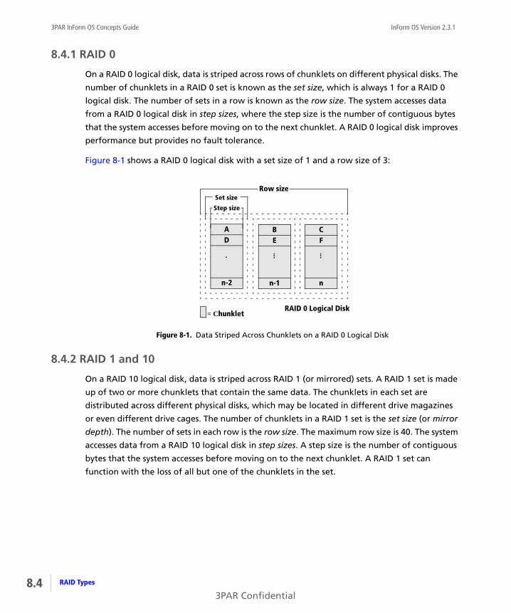
8.4
3PAR InForm OS Concepts Guide InForm OS Version 2.3.1
8.4.1 RAID 0
On a RAID 0 logical disk, data is striped across rows of chunklets on different physical disks. The
number of chunklets in a RAID 0 set is known as the set size, which is always 1 for a RAID 0
logical disk. The number of sets in a row is known as the row size. The system accesses data
from a RAID 0 logical disk in step sizes, where the step size is the number of contiguous bytes
that the system accesses before moving on to the next chunklet. A RAID 0 logical disk improves
performance but provides no fault tolerance.
Figure 8-1 shows a RAID 0 logical disk with a set size of 1 and a row size of 3:
Figure 8-1. Data Striped Across Chunklets on a RAID 0 Logical Disk
8.4.2 RAID 1 and 10
On a RAID 10 logical disk, data is striped across RAID 1 (or mirrored) sets. A RAID 1 set is made
up of two or more chunklets that contain the same data. The chunklets in each set are
distributed across different physical disks, which may be located in different drive magazines
or even different drive cages. The number of chunklets in a RAID 1 set is the set size (or mirror
depth). The number of sets in each row is the row size. The maximum row size is 40. The system
accesses data from a RAID 10 logical disk in step sizes. A step size is the number of contiguous
bytes that the system accesses before moving on to the next chunklet. A RAID 1 set can
function with the loss of all but one of the chunklets in the set.
AD
n-2
.
Step size
Set sizeRow size
= ChunkletRAID 0 Logical Disk
BE
n-1
...
CF
n
...
RAID Types
3PAR Confidential
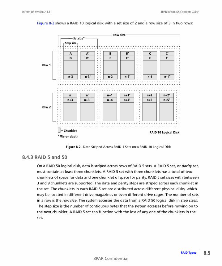
InForm OS Version 2.3.1 3PAR InForm OS Concepts Guide
Figure 8-2 shows a RAID 10 logical disk with a set size of 2 and a row size of 3 in two rows:
Figure 8-2. Data Striped Across RAID 1 Sets on a RAID 10 Logical Disk
8.4.3 RAID 5 and 50
On a RAID 50 logical disk, data is striped across rows of RAID 5 sets. A RAID 5 set, or parity set,
must contain at least three chunklets. A RAID 5 set with three chunklets has a total of two
chunklets of space for data and one chunklet of space for parity. RAID 5 set sizes with between
3 and 9 chunklets are supported. The data and parity steps are striped across each chunklet in
the set. The chunklets in each RAID 5 set are distributed across different physical disks, which
may be located in different drive magazines or even different drive cages. The number of sets
in a row is the row size. The system accesses the data from a RAID 50 logical disk in step sizes.
The step size is the number of contiguous bytes that the system accesses before moving on to
the next chunklet. A RAID 5 set can function with the loss of any one of the chunklets in the
set.
AD
n-3
Set size*Step size
Row size
= Chunklet RAID 10 Logical Disk*Mirror depth
A‘D‘
n-3‘
BE
n-2
B‘E‘
n-2‘
CF
n-1
C‘F‘
n-1‘
nn+3
n‘n+3‘
n+1n+4
n+1‘n+4‘
n+2n+5
n+2‘n+5‘
Row 1
Row 2
8.5RAID Types
3PAR Confidential

8.6
3PAR InForm OS Concepts Guide InForm OS Version 2.3.1
Figure 8-3 shows a RAID 50 logical disk with a set size of 3, and 2 sets in 1 row:
Figure 8-3. Data Striped Across RAID 5 Sets on a RAID 50 Logical Disk
8.4.4 RAID Multi-Parity
On a RAID Multi-Parity (MP) or RAID 6 logical disk, data is striped across rows of RAID MP sets.
A RAID MP set, or double parity set, must contain at least 8 chunklets. A RAID MP set with 8
chunklets has a total of 6 chunklets of space for data and 2 chunklets of space for parity. RAID
MP set sizes of 8 and 16 chunklets are supported. The data and parity steps are striped across
each chunklet in the set. The chunklets in each RAID MP set are distributed across different
physical disks, which may be located in different drive magazines or even different drive cages.
The number of sets in a row is the row size. The system accesses the data from a RAID MP
logical disk in step sizes. The step size varies and is dependent on the size of the RAID MP set. A
RAID MP set can function with the loss of any two of the chunklets in the set.
Ap (E,F)
BE
p (A,B)F
Cp (G,H)
DG
p (C,D)H
Step size
Set size*Row size
RAID 50 Logical Disk= Chunklet
*Parity set
p (I,J) p (K,L)I J K L
p = Parity step
RAID Types
3PAR Confidential

InForm OS Version 2.3.1 3PAR InForm OS Concepts Guide
The following example shows 2 RAID MP sets in one row, the second set is shown below the
first set. In the first RAID MP set in the following example, p0 is the parity step for data steps F,
L, M, Q, T, V, and X. Figure 8-4 shows a RAID MP logical disk with a set size of 8, and 2 sets in 1
row:
Figure 8-4. Data Striped Across RAID MP Sets on a RAID MP Logical Disk
RAID MP Logical Disk
AB
Set 1 Row 1
Cp0
= Chunklet
p = Parity step
...W1
X1
Y1p8
DE
Fp1
Z1
A2
B2p9
GH
Ip2
C2
D2
E2p10
JK
Lp3
F2
G2
H2p11
MN
Op4
I2
J2
K2p12
PQ
Rp5
L2
M2
N2p13
ST
Up6
O2
P2
Q2p14
VW
Xp7...
R2
S2
T2p15...
...YZ
A1p16
...U2
V2
W2p24
B1C1
D1p17
X2
Y2
Z2p25
E1F1
G1p18
A3
B3
C3p26
H1I1
J1p19
D3
E3
F3p27
K1L1
M1p20
G3
H3
I3p28
N1O1
P1p21
J3
K3
L3p29
Q1R1
S1p22
M3
N3
O3p30
T1U1
V1...p23
P3
Q3
R3p31...
Set 2 Row 1
8.7RAID Types
3PAR Confidential

8.8
3PAR InForm OS Concepts Guide InForm OS Version 2.3.1
8.5 Logical Disk Size and RAID TypesA logical disk is a collection of physical disk chunklets, each 256 MB, that have been arranged
as rows of RAID sets. For this reason, the total size of a logical disk is a multiple of the user
space within a single logical disk RAID set.
For RAID 0 and RAID 1 logical disks, the user space within each RAID set is equal to one
chunklet, or 256 MB. Therefore, for RAID 0 and RAID 1 logical disks, the total logical disk size is
always a multiple of 256 MB. When creating a RAID 0 or RAID 1 logical disk, the system
automatically rounds up to the next multiple of 256 MB when you specify a logical disk size
that is not a multiple of 256 MB. For example, if you specify a size of 1000 MB when creating a
RAID 0 logical disk, the result will be a RAID 0 logical disk with a user space of 1024 MB.
For RAID 5 logical disks, the total size of the logical disk is determined by the number of data
chunklets in the RAID set. A RAID 5 set, or parity set, must contain at least three chunklets. A
RAID 5 set with three chunklets has a total of two chunklets of space for data and one
chunklet of space for parity. The system default is four chunklets: three for data and one for
parity (3+1). When creating a RAID 5 logical disk with this default 3+1 layout, the system
automatically rounds up so that the logical disk size reflects one chunklet, or 256 MB, for each
data chunklet in the RAID set. For example, if you specify a size of 750 MB when creating a
RAID 5 logical disk with the default set size of 4 chunklets, the result is a logical disk with a
user space of 768 MB (3 x 256 MB). The minimum size for a RAID 5 logical disk is 768 MB.
For RAID MP logical disks, the total size of the logical disk is determined by the number of data
chunklets in the RAID set. A RAID MP set, or double parity set, must contain at least 8
chunklets. RAID MP set sizes of 8 and 16 chunklets are supported. The system default is 8
chunklets. A RAID MP set with 8 chunklets has a total of 6 chunklets of space for data and 2
chunklets of space for parity (6+2). When creating a RAID MP logical disk with this default 6+2
layout, the system automatically rounds up so that the logical disk size reflects one chunklet, or
256 MB, for each data chunklet in the RAID set. For example, if you specify a size of 1,500 MB
when creating a RAID MP logical disk with the default set size of 8 chunklets, the result is a
logical disk with a user space of 1,536 MB (6 x 256 MB). The minimum size for a RAID MP
logical disk is 1,536 MB.
Logical Disk Size and RAID Types
3PAR Confidential

InForm OS Version 2.3.1 3PAR InForm OS Concepts Guide
8.6 Logical Disk Size and Virtual VolumesRounding up of logical disk size by the system may occur when creating virtual volumes. When
you create a virtual volume, the system automatically creates the necessary underlying logical
disks to support that volume. When the specified virtual volume size is less than the sum of the
logical disks created to support that volume, those logical disks will have some unused space.
For example, when creating a RAID 5 virtual volume with a default set size of 4 and a total size
of 1024 MB, the system automatically creates two 768 MB logical disks to support that volume.
However, because the requested volume size is only 1024 MB, only 512 MB of each RAID 5
logical disk is actually used by the virtual volume.
8.7 Logical Disk Size and Common Provisioning GroupsWhen creating a common provisioning group, the system may round up to determine the
initial allocation as well as the growth increment that determines the size of subsequent
allocations that occur as the CPG grows over time. For example, when creating a RAID 5 CPG
with the default set size of 4 and a growth increment of 8192 MB, the system will
automatically create a CPG with an initial user size of 8448 MB and a growth increment of 8448
MB. The system must round up the user space because the CPG requires 11 RAID 5 sets, each
with a size of 768 MG (3 x 256 MB). Together, these 11 RAID 5 sets total 8448 MB (11 x 768 MB).
The CPG does not show any user space until its first virtual volume is created.
8.9Logical Disk Size and Virtual Volumes
3PAR Confidential

8.10
3PAR InForm OS Concepts Guide InForm OS Version 2.3.1
Logical Disk Size and Common Provisioning Groups
3PAR Confidential

InForm OS Version 2.3.1 3PAR InForm OS Concepts Guide
9Common Provisioning Groups
In this chapter
9.1 Overview 9.2
9.2 Precautions and Planning 9.3
9.2.1 Growth Increments, Warnings, and Limits 9.3
9.2.2 Growth Increment 9.4
9.2.3 Growth Warning 9.5
9.2.4 Growth Limit 9.5
9.3 System Guidelines for Creating CPGs 9.6
9.4 Volume Types Associated with CPGs 9.7
The purpose of this chapter is to provide planning considerations for Common Provisioning
Groups.
9.1Common Provisioning Groups
3PAR Confidential

9.2
3PAR InForm OS Concepts Guide InForm OS Version 2.3.1
9.1 OverviewA Common Provisioning Group (CPG) creates a virtual pool of logical disks that allows up to
4,095 virtual volumes to share the CPG's resources and allocates space on demand. You can
create fully-provisioned virtual volumes and Thinly-Provisioned Virtual Volumes (TPVVs) that
draw space from the CPG's logical disk pool.
CPGs enable fine-grained, shared access to pooled logical capacity. Instead of pre-dedicating
logical disks to volumes, the CPG allows multiple volumes to share the buffer pool of logical
disks. For example, when a TPVV is running low on user space, the system automatically assigns
more capacity to the TPVV by mapping new regions from logical disks in the CPG associated
with that TPVV. As a result, any large pockets of unused but allocated space are eliminated.
Fully-provisioned virtual volumes cannot create user space automatically and the system
allocates a fixed amount of user space for the volume.
By default, a CPG is configured to auto-grow new logical disks when the amount of available
logical disk space falls below a configured threshold. The initial buffer pool of logical disks
starts off at a fraction of the exported virtual capacity of mapped volumes and automatically
grows over time as required by application writes.
Creating CPGs can be performed with both the 3PAR InForm Command Line Interface (CLI) and
the 3PAR InForm Management Console. Refer to the 3PAR InForm OS CLI Administrator’s
Manual and the 3PAR InForm Management Console Online Help for instructions on how to
perform these tasks.
For more information about TPVVs and fully-provisioned virtual volumes, see Chapter 10,
Virtual Volumes.
Overview
3PAR Confidential

InForm OS Version 2.3.1 3PAR InForm OS Concepts Guide
9.2 Precautions and PlanningA Common Provisioning Group (CPG) creates a virtual pool of logical disks that allows up to
4,095 volumes to share the CPG's resources and allocate space on demand. However, CPGs still
require careful planning and monitoring to prevent them from becoming so large that they set
off the system's built-in safety mechanisms. These safety mechanisms are designed to prevent a
CPG from consuming all free space on the system, but they only work properly on systems that
are planned carefully and monitored closely.
9.2.1 Growth Increments, Warnings, and Limits
You can create several types of volumes that draw space from the CPG's logical disk pool as
needed. When creating a CPG, set a growth increment and an optional growth warning and
growth limit to restrict the CPG's growth and maximum size. It is important to plan the CPG's
growth increment, growth warning, and growth limit carefully and then continue to monitor
the CPG closely over time.
CAUTION: Use caution in planning CPGs. The system does not prevent you from
setting growth warnings or growth limits that exceed the amount of currently
available storage on a system. When volumes associated with a CPG use all space
available to that CPG, any new writes to TPVVs associated with the CPG will fail
and/or snapshot volumes associated with the CPG may become invalid or stale.
Under these conditions, some host applications do not handle write failures
gracefully and may produce unexpected failures.
NOTE: By default, the growth warning and growth limit are set to none, which
effectively disables these safety features.
9.3Precautions and Planning
3PAR Confidential

9.4
3PAR InForm OS Concepts Guide InForm OS Version 2.3.1
9.2.2 Growth Increment
As volumes that draw from a CPG require additional storage, the system automatically creates
additional logical disks according to the CPG's growth increment. The default growth
increment is fixed at 32 GB, but the minimum growth increment varies according to the
number of controller nodes in the system and ranges from 8 GB for a two-node system to 32
GB for a four-node system (Table 9-1).
In some it may be desirable to use a larger growth increment. However, a smaller growth
increment can prevent the CPG from automatically allocating too much space.
The optimal growth increment depends on several factors:
■ Total available space on your system.
■ Nature of the data running on the system.
■ Number of CPGs in the system.
■ Number of volumes associated with those CPGs.
■ Anticipated growth rate of the volumes associated with the CPGs.
Table 9-1. Default and Minimum Growth Increments
Number of nodes Default Minimum
2 32 GB 8 GB
4 32 GB 16 GB
6 32 GB 24 GB
8 32 GB 32 GB
NOTE: The system may round up when creating logical disks to support virtual
volumes and Common Provisioning Groups (CPGs), resulting in a discrepancy
between the user-specified size or growth increment and the actual space
allocated to logical disks created by the system. For a detailed discussion of this
issue, see Logical Disk Size and RAID Types on page 8.8.
Precautions and Planning
3PAR Confidential

InForm OS Version 2.3.1 3PAR InForm OS Concepts Guide
9.2.3 Growth Warning
When the size of the volumes that draw from a CPG reach the CPG’s growth warning, the
system generates an alert to notify you of the CPG's increasing size. This safety mechanism
provides the opportunity to take early action that may prevent snapshot volumes associated
with the CPG from experiencing failures, causing host or application write failures, and
exhausting all free space on the system.
When setting growth warnings for CPGs, it is critical to consider the number of CPGs on the
system, the total capacity of the system, and the projected rate of growth for all volumes on
the system.
The storage system does not prevent you from setting growth warnings that exceed the total
capacity of the system. For example, on a 3 TB system you can create two CPGs that each have
a growth warning of 2 TB. However, if both CPGs grow at a similar rate, it is possible for the
volumes that draw from the CPGs to consume all free space on the system before either CPG
reaches the growth warning threshold.
9.2.4 Growth Limit
If the volumes that draw from a CPG are allowed to reach the CPG’s growth limit, the system
prevents them from allocating additional space. This safety mechanism stops a runaway
application or volume from exhausting all free space available to the CPG and causing invalid
(stale) snapshot volumes and/or new application write failures for volumes associated with
that CPG. However, the storage system does not prevent you from setting growth limits that
exceed the total capacity of the system. For example, on a 4 TB system it is possible to create a
CPG with a 5 TB growth limit. Likewise, it is possible to create five CPGs, each with a 2 TB
growth limit, etc.
In addition, volumes that draw from a CPG can only use the space available to that CPG based
on the CPG's logical disk parameters. For example, if you create a CPG that only uses logical
disks that belong to controller node 0, when the virtual volumes that draw from a CPG have
filled up all space available to that CPG based on it's logical disk parameters, the following will
happen:
■ New writes to any Thinly-Provisioned Virtual Volumes (TPVVs) mapped to that CPG will
return write failures.
■ Snapshot volumes mapped to the CPG may become invalid (stale), subject to the virtual
copy policy associated with the base volume.
For base volumes with a no stale snapshots virtual copy policy, new writes to the base
volume will result in write failures.
9.5Precautions and Planning
3PAR Confidential

9.6
3PAR InForm OS Concepts Guide InForm OS Version 2.3.1
■ For base volumes with a stale snapshots virtual copy policy, new writes will cause
snapshot volumes to become invalid (stale).
■ If the volumes that draw from a CPG reach the CPG’s growth limit, the system generates
additional alerts to notify you that all logical capacity for the CPG has been consumed.
9.3 System Guidelines for Creating CPGsUse the following guidelines to ensure maximum performance and optimal reliability in the
volumes supported by those logical disks:
■ To provide the highest availability, chunklets in the same RAID set should be from different
drive cages, and then different drive magazines.
■ Physical disks with fewer used chunklets should be used before physical disks with more
used chunklets.
■ Chunklets in the same row should be from different physical disks. In other words, a
physical disk should not appear twice in the same row.
■ Chunklets should belong to a disk that is connected through the primary path to the logical
disk’s owner node.
■ The system should use as many physical disks as possible.
■ The load on all physical disks should be balanced.
■ The system should use the largest possible row size.
NOTE: The system may round up when creating logical disks to support virtual
volumes and Common Provisioning Groups (CPGs), resulting in a discrepancy
between the user-specified size or growth increment and the actual space
allocated to logical disks created by the system. For more information, see Logical
Disk Size and RAID Types on page 8.8.
System Guidelines for Creating CPGs
3PAR Confidential
InForm OS Version 2.3.1 3PAR InForm OS Concepts Guide
9.4 Volume Types Associated with CPGsDepending on the products and features licensed for use on the system, after creating a CPG
you can create two types of base volumes that draw from the CPG's logical disk pool: Thinly-
Provisioned Virtual Volumes (TPVVs) and fully-provisioned virtual volumes. These two volume
types draw from the pool in different ways. For information about TPVVs, see Thinly-
Provisioned Virtual Volumes on page 10.4. For information about fully-provisioned virtual
volumes, see Fully-Provisioned Virtual Volumes on page 10.3.
9.7Volume Types Associated with CPGs
3PAR Confidential

9.8
3PAR InForm OS Concepts Guide InForm OS Version 2.3.1
Volume Types Associated with CPGs
3PAR Confidential

InForm OS Version 2.3.1 3PAR InForm OS Concepts Guide
10Virtual Volumes
In this chapter
10.1 Overview 10.1
10.2 Virtual Volume Types 10.2
10.2.1 Administrative Volumes 10.3
10.2.2 Fully-Provisioned Virtual Volumes 10.3
10.2.3 Thinly-Provisioned Virtual Volumes 10.4
10.3 Physical Copies 10.6
10.4 Virtual Copy Snapshots 10.7
10.5 Exporting Virtual Volumes 10.11
The purpose of this chapter is to explain how different types of virtual volumes and copies of
volumes function, and to provide planning considerations for creating your own virtual
volumes.
10.1 OverviewVolumes draw their resources from Common Provisioning Groups (CPGs), and volumes are
exported as Logical Unit Numbers (LUNs) to hosts. Virtual volumes are the only data layer
10.1Virtual Volumes
3PAR Confidential

10.2
3PAR InForm OS Concepts Guide InForm OS Version 2.3.1
visible to hosts. You can create physical copies or virtual copy snapshots of virtual volumes for
use if the original base volume becomes unavailable. Before creating virtual volumes, you must
first create CPGs to allocate space to the virtual volumes.
Volumes can be grouped into autonomic groups that can be managed as one volume. If you
have a group of volumes that require the same administrative procedures, it is easier to group
those volumes into an autonomic group and mange them together.
Creating virtual volumes can be performed with both the 3PAR InForm Command Line
Interface (CLI) and the 3PAR InForm Management Console. Refer to the 3PAR InForm OS CLI
Administrator’s Manual and the 3PAR InForm Management Console Online Help for
instructions on how to perform these tasks.
For information about CPGs, see Chapter 9, Common Provisioning Groups.
10.2 Virtual Volume TypesThere are three types of virtual volumes:
■ Fully-provisioned virtual volumes
■ Thinly-Provisioned Virtual Volumes (TPVVs)
■ Administrative Volumes
Administrative volumes are created by the system and are for system usage only.
Fully-provisioned virtual volumes and TPVVs have three separate data components:
■ User space is the area of the volume that corresponds to the logical disk regions in the CPG
available to the host. The user space contains the user data and is exported as a LUN to the
host.
■ Snapshot space, also known as copy space, is the area of the volume that corresponds to
logical disk regions in the CPG containing copies of user data that changed since the
previous snapshot of the volume was created. The snapshot space contains the copy data.
NOTE: Creating Thinly-Provisioned Virtual Volumes (TPVVs) requires the 3PAR
Thin Provisioning license. Creating virtual copies requires the 3PAR Virtual Copy
license. For more information, see 3PAR InForm Software on page 2.7.
Virtual Volume Types
3PAR Confidential

InForm OS Version 2.3.1 3PAR InForm OS Concepts Guide
■ Administration space, also known as admin space, is the area of the volume that
corresponds to logical disk regions in the CPG that track changes to the volume since the
previous snapshot was created. The administration space contains pointers to copies of user
data in the snapshot space. Administration space is managed by the system, not with the
tools you use to manage user and snapshot space.
You can increase the size of volumes, the amount of user space, and the amount of snapshot
space for volumes as the requirements increase. If the user space and snapshot space use all
available space, the 3PAR Virtual Copy feature’s copy-on-write operation will fail. To avoid
running out of user space, use TPVVs to automatically draw more user space from a CPG. The
InForm OS automatically reclaims unused snapshot from TPVVs and fully-provisioned virtual
volumes and returns the space to the logical disks.
For greater administrative flexibility, you can provision the virtual volume’s user space and
snapshot space from the same or different CPGs. If the virtual volume’s user space and
snapshot space are on a different CPGs, the user space remains available to the host if the CPG
containing the snapshot space becomes full. To save time by not repeating tasks, you can
create many identical virtual volume’s at one time.
10.2.1 Administrative Volumes
As part of installation and setup process, a volume called the administrative volume, or admin
volume, is created on the system. This volume is used by the system to store administrative
data such as the system event log. The admin volume is always named admin. This volume
cannot be exported and cannot be removed from the system.
10.2.2 Fully-Provisioned Virtual Volumes
A fully-provisioned virtual volume is a volume that uses logical disks that belong to a logical
disk pool known as a Common Provisioning Group (CPG). Unlike Thinly-Provisioned Virtual
Volumes (TPVVs), fully-provisioned virtual volumes have a set amount of user space allocated
in the system for user data. They require the system to reserve the entire amount of space
required by the fully-provisioned virtual volume wether or not the space is actually used. The
fully-provisioned virtual volume size is fixed, and the size limit is 16 TB. You can set snapshot
space allocation limits and usage warnings to help manage the growth of snapshot space.
CAUTION: It is strongly recommended that you do not tamper with the admin
volumes.
10.3Virtual Volume Types
3PAR Confidential

10.4
3PAR InForm OS Concepts Guide InForm OS Version 2.3.1
10.2.3 Thinly-Provisioned Virtual Volumes
With a 3PAR Thin Provisioning license, you can also create Thinly-Provisioned Virtual Volumes
(TPVVs). A TPVV uses logical disks that belong to a logical disk pool known as a Common
Provisioning Group (CPG). TPVVs associated with the same CPG draw user space from that pool
as needed, allocating space on demand in small increments beginning with 256 MB per
controller node. As the volumes that draw space from the CPG require additional storage, the
system automatically creates additional logical disks and adds them to the pool until the CPG
reaches the user-defined growth limit that restricts the CPG’s maximum size. The TPVV volume
size limit is 16 TB.
TPVVs are capable of responding to host write requests by allocating space on demand in small
increments, beginning with 256 MB per controller node supporting the TPVV. These allocations
are adaptive since subsequent allocations are based on the rate of consumption for previously
allocated space. With 256 MB per node as the default, allocations increase by increments of
256 MB per node as the system demands. For example, if a TPVV is initially allocated 256 MB
per node but then consumes that space in less than sixty seconds, the next allocation becomes
512 MB per node. However, if the initial 256 MB per node is consumed more slowly, the next
allocation increment remains at 256 MB per node. Under this provisioning scheme, the
maximum allocation increment is 1 GB per controller node supporting the TPVV. In addition, as
the TPVV reaches either its exported size or its user-defined allocation limit, the system allows
allocation of an additional 128 MB per node beyond these limits in order to ensure that the
exported TPVV address space is usable.
CAUTION: Use of allocation limits is recommended to prevent consumption of
physical raw capacity beyond a tolerable limit. However, you should exercise
caution when setting the value of the allocation limit. Upon reaching the
allocation limit, any new writes to TPVVs will fail and/or snapshot volumes
associated with the CPG may become invalid. Under this condition, some host
applications do not handle write failures gracefully and may produce unexpected
failures.
CAUTION: Do not allow the volumes that draw from a CPG to exceed the CPG’s
growth limit. Doing so can invalidate snapshot volumes. Refer to Chapter 9,
Common Provisioning Groups for additional cautions and recommendations.
Virtual Volume Types
3PAR Confidential

InForm OS Version 2.3.1 3PAR InForm OS Concepts Guide
10.2.3.1 TPVV Warnings and Limits
The TPVV volume size limit is 16 TB. When creating a TPVV, you have the option to set an
allocation warning threshold and an allocation limit threshold.
■ allocation warning threshold:
For volumes capable of allocating space on demand, the user-defined threshold at which
the system generates an alert. This threshold is a percentage of the volume's virtual size,
the size that the volume presents to the host.
■ allocation limit threshold:
For volumes capable of allocating space on demand, the user-defined threshold at which
writes fail, preventing the volume from consuming additional resources. This threshold is a
percentage of the volume's virtual size, the size that the volume presents to the host.
When setting TPVV allocation warnings and allocation limits, you must take into account the
space to be consumed by both the volume’s user data and the snapshot data.
The total amount of snapshot space consumed by a TPVV and its snapshots includes the data
written to the base volume and the data written to the snapshots. The size of the data written
to the snapshots equals the total writes to the base volume since the oldest existing read-only
(RO) snapshot was created.
When deciding on the allocation warning and allocation limit thresholds for a TPVV, you can
use an estimate of the maximum write rate to compute the snapshot data growth rate.
■ If there are no RO snapshots, and the volume is not a physical copy or used for Remote
Copy, use the maximum write rate as the growth rate.
■ If there are RO snapshots, or if the volume is not a physical copy or used for Remote Copy,
use twice the maximum write rate as the growth rate.
■ Set the allocation warning and limit thresholds based on the growth rate and how much
advance warning you require before the volume reaches its limit and writes fail.
Use the following formula to generate the allocation warning threshold:
where the value of n is as follows:
◆ for a TPVV without read-only snapshots, and when that TPVV is not a physical copy or
used for Remote Copy, n=1.
n write rate warning period
volume’s virtual sizeAllocation warning = 1 —
• •
percentage• 100
10.5Virtual Volume Types
3PAR Confidential

10.6
3PAR InForm OS Concepts Guide InForm OS Version 2.3.1
◆ for a TPVV with read-only snapshots, or when that TPVV is a physical copy or used for
Remote Copy, n=2.
For example, if a 1 TB TPVV with read-only snapshots has a maximum write rate of 1 GB per
day and you would like 30 days warning prior to that TPVV reaching the allocation limit,
use the following calculation for the allocation warning percentage:
10.3 Physical CopiesA physical copy is a point-in-time copy that duplicates all the data from one original base
volume to another volume called the destination volume. This is done so that the data on the
destination volume can be used if the original base volume becomes unavailable. Any changes
to either volume causes them to lose synchronization with each other, which is corrected by
resynchronizing the two volumes as described in the InForm OS CLI Administrator’s Manual
and the InForm OS Management Console Online Help. No special license is required to create a
physical copy of a volume.
Physical copies can be created and managed in groups to reduce the number of management
tasks. You can create a consistent group physical copies form a list of virtual volumes, and
group physical copies into autonomic groups that are managed as one physical copy.
A physical copy can only be made from a volume with enough free space to accommodate
writes to that volume during the physical copy operation. In addition, the destination volume
must meet the following conditions:
■ It must have snapshot space associated with.
■ It must have at least as much user space as the volume being copied.
■ It must not be exported to a host.
2 1 GB per day
1024 GBAllocation warning = 1 —
• • 30 days= 94 %• 100
percentage
NOTE: If the base and destination volume are both Thinly-Provisioned Virtual
Volumes (TPVVs), only the space that is actually used is copied. See Chapter 2,
Overview for additional information on TPVVs.
Physical Copies
3PAR Confidential

InForm OS Version 2.3.1 3PAR InForm OS Concepts Guide
10.4 Virtual Copy SnapshotsA virtual copy is a snapshot of another virtual volume. You can make virtual copies of base
volumes, physical copies, or other virtual copies. Virtual copies are created using copy-on-write
techniques available only with the 3PAR Virtual Copy license. Unlike a physical copy which
duplicates the entire base volume, a virtual copy only records the changes to the original
volume. This allows an earlier state of the original volume to be recreated by starting with the
current state and rolling back all of the changes that have been made since the virtual copy
was created.
The system allows you to make a maximum of 500 virtual copies of a base volume. Up to 256
virtual copies can be read/write copies. System-level maximums of total virtual copies that can
be created on a system also apply. Refer to the 3PAR InForm OS Configuration Matrix for
system-level maximum limits on virtual copies.
Virtual copies can be created and managed in groups to reduce the number of management
tasks. You can create a consistent group virtual copies form a list of virtual volumes, and group
virtual copies into autonomic groups that are managed as one virtual copy.
10.4.1 Virtual Copy Snapshot Relationships
Base volumes are always read/write, but virtual copies can be read/write or read-only. The rules
that govern the relationships between a base volume and its virtual copies are based upon the
difference between read/write and read-only volumes. Read-only and read/write copies must
alternate. You can only make a read-only copy of a read/write volume, and you can only make
a read/write copy of a read-only volume. Since base volumes are always read/write, you can
NOTE: 3PAR virtual copies are consistent at the 3PAR virtual volume level, but not
at the host file-system or application level. In other words, virtual copies only
preserve the data that was written on the source 3PAR virtual volume before the
virtual copy is created. Virtual copies do not preserve the data that is resident
within the application or file-system buffers and is not flushed to disk before the
virtual copy is created.
3PAR offers optional 3PAR Recovery Manager DBA software to enable
application-level consistent snapshots. Contact 3PAR Customer Support for more
information.
10.7Virtual Copy Snapshots
3PAR Confidential

10.8
3PAR InForm OS Concepts Guide InForm OS Version 2.3.1
only create read-only copies of a base volume. See Figure 10-1 for an example of alternating
read-only and read/write virtual copy relationships.
Figure 10-1. Alternating Read-only and Read/Write Virtual Copies
See Figure 10-2 for a more complex example of the possible relationships between a parent
base volume and its virtual copies.
Figure 10-2. Base Volume and Virtual Copy Relationships
RW=read/writeRO=read-only
RO
RW
RO RO
RW
RO RO
RO
RW
RO
RW
RO
RW
RO
BASE VOLUME (RW)
RW = read/writeRO = read-only
BASE VOLUME (RW)
RO
RW
RO
RORORORO...
..
RWRWRWRW.
RO
RW
RO RO
..
RWRWRWRW.
RORORORO...
RW
RO
RW
RO
RORORORO...
..
RWRWRWRW.
RO
RW
RO RO
..
RWRWRWRW.
RORORORO...
RW
RO
RW
RO
RORORORO...
..
RWRWRWRW.
RO
RW
RO RO
..
RWRWRWRW.
RORORORO...
RW
RO
RW
RO
RORORORO...
..
RWRWRWRW.
RO
RW
RO RO
..
RWRWRWRW.
RORORORO...
RW
RO
RW
RO
RORORORO...
..
RWRWRWRW.
RO
RW
RO RO
..
RWRWRWRW.
RORORORO...
RW
Virtual Copy Snapshots
3PAR Confidential
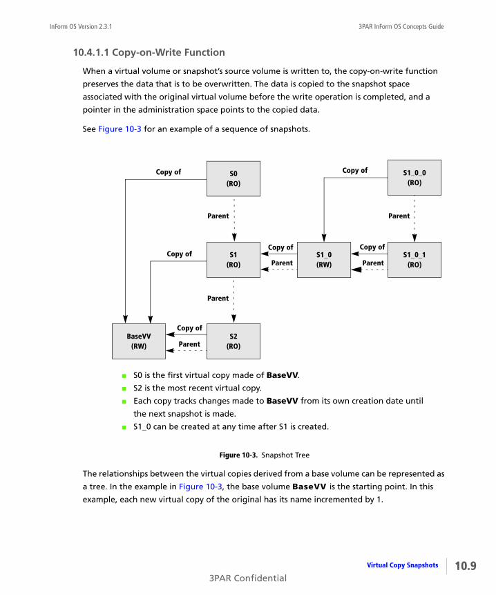
InForm OS Version 2.3.1 3PAR InForm OS Concepts Guide
10.4.1.1 Copy-on-Write Function
When a virtual volume or snapshot’s source volume is written to, the copy-on-write function
preserves the data that is to be overwritten. The data is copied to the snapshot space
associated with the original virtual volume before the write operation is completed, and a
pointer in the administration space points to the copied data.
See Figure 10-3 for an example of a sequence of snapshots.
Figure 10-3. Snapshot Tree
The relationships between the virtual copies derived from a base volume can be represented as
a tree. In the example in Figure 10-3, the base volume BaseVV is the starting point. In this
example, each new virtual copy of the original has its name incremented by 1.
BaseVV(RW)
S0(RO)
S1(RO)
S2(RO)
Parent
Parent
S1_0(RW)Parent
Copy ofS1_0_1
(RO)Parent
Copy of
S1_0_0(RO)
Copy of
Copy of
Parent
Copy of
Parent
Copy of
■ S0 is the first virtual copy made of BaseVV.
■ S2 is the most recent virtual copy.
■ Each copy tracks changes made to BaseVV from its own creation date until
the next snapshot is made.
■ S1_0 can be created at any time after S1 is created.
10.9Virtual Copy Snapshots
3PAR Confidential

10.10
3PAR InForm OS Concepts Guide InForm OS Version 2.3.1
Each copy of a copy has an additional level added to its name: in this example, the first copy of
S1 is S1_0, and a copy of S1_0 is S1_0_0. Unlike the automatic snapshots created for physical
copies, these snapshots are not assigned names by the system.
The following rules are enforced by the system when you create a snapshot:
■ The tree grows in alternating layers of read/write and read-only snapshots. You can only
make a read-only copy of a read/write volume, and you can only make a read/write copy of
a read-only volume.
■ A maximum of 256 read/write virtual copies can be made from one read-only virtual
volume.
■ A maximum of 500 virtual copies can be made from one base volume.
■ A virtual volume cannot be deleted if a child copy of it exists. For example, S1 cannot be
removed unless S1_0, S1_0_0, and S1_0_1 are deleted first.
10.4.1.2 Copy-of and Parent Relationships
In the example in Figure 10-3, there are two different tree structures: the solid arrows show
the copy-of relationships, and the dashed arrows show the parent relationship. For example,
S0 is a read-only copy of BaseVV, and S1 is the parent of S0. The copy-of relationship simply
shows that the snapshot was created by copying another virtual volume. The parent
relationship refers to the internal organization of the administration space. The parent volume
contains information needed to reconstruct the snapshot represented by the child volume. A
parent volume can have a creation date after that of its child if the parent volume was
modified.
The parent relationship is useful for two reasons:
■ Understanding the performance consequences of virtual copies. The tree representing the
parent relationship shows the look-up paths in the administration space needed to
reconstruct the earlier state of the virtual volume. The farther away a virtual copy is from
the base volume, the longer it will take to retrieve it. If a snapshot is expected to be kept in
use for a long time, consider making a physical copy instead of a virtual copy.
NOTE: The naming convention used in the example above is recommended, but it
is not enforced by the system. You can name each virtual volume and virtual copy
at the time of creation.
Virtual Copy Snapshots
3PAR Confidential
InForm OS Version 2.3.1 3PAR InForm OS Concepts Guide
■ Understanding which virtual copies become stale if the administration space is full and the
copy-on-write data cannot be written. A stale snapshot is one that cannot be completely
recreated because the most recent changes will not be included. The current snapshot and
all its children become stale when a write fails. For example, if there is no space to write the
copy-on-write data when a host writes to S1_0, then S1_0, S1_0_1, and S1_0_0 become
stale.
10.5 Exporting Virtual VolumesVirtual volumes are the only data layer component visible to hosts. You export a virtual volume
to make it available to one or more hosts by creating an association between the volume and a
logical unit number (LUN). The characteristics of this association are defined when you create a
Virtual Volume-LUN pairing (VLUN). A VLUN is a pairing between a virtual volume and a LUN
expressed as either a VLUN template or an active VLUN.
Exporting virtual volumes can be performed with both the 3PAR InForm Command Line
Interface (CLI) and the 3PAR InForm Management Console. Refer to the 3PAR InForm OS CLI
Administrator’s Manual and the 3PAR InForm Management Console Online Help for
instructions on how to perform this task.
10.5.1 VLUN Templates and Active VLUNs
A VLUN template sets up an association between a virtual volume and a LUN-host, LUN-port,
or LUN-host-port combination by establishing the export rule, or the manner in which the
volume is exported. When you create a VLUN template, if the current system state meets the
conditions established by the VLUN template, that template is immediately applied to create
one or more active VLUNs. These active VLUNs enable virtual volumes to be exported to hosts.
If the current system state does not meet the conditions of the VLUN template, no active
VLUNs are created until the conditions of the template are met.
Once a VLUN template is applied to create one or more active VLUNs, hosts continue to be able
to access volumes based on the export rule established by that template. Removing VLUNs
associated with a volume halts host access to that volume. Removing all VLUNs for a host stops
the host from accessing all volumes.
10.5.2 VLUN Template Types
A VLUN template sets up an association between a virtual volume and a LUN-host, LUN-port,
or LUN-host-port combination by establishing the export rule, or the manner in which the
volume is exported. A VLUN template enables the export of a virtual volume as a VLUN to a
10.11Exporting Virtual Volumes
3PAR Confidential
10.12
3PAR InForm OS Concepts Guide InForm OS Version 2.3.1
host or hosts. Those volume exports, which are seen as LUNs by the host or hosts, are active
VLUNs.
A VLUN template can be one of the following types:
■ Host sees allows only a specific host to see a volume.
■ Host set allows any host that is a member of the host set to see a volume.
■ Port presents allows any host on a specific port to see the volume.
■ Matched set allows only a specific host on a specific port to see the volume.
10.5.2.1 Host Sees
A host sees VLUN template allows only a particular host connected to any port to see a virtual
volume. The system makes the virtual volume visible as a LUN to all the host’s WWNs,
regardless of which controller node port the WWNs appear on. If the host has more than one
WWN, active VLUNs are created for each host WWN. However, for any single host, there can
only be one host sees VLUN template for a given LUN.
If a WWN is added to an existing host definition, all virtual volumes that are exported to the
host using the host-sees VLUN template are exported to the new WWN. However, WWNs
cannot be removed from a host definition if a LUN is exported to the host.
10.5.2.2 Host Set
A host set VLUN template allows any host that is a member of the host set to see a volume. The
system makes the virtual volume visible as a LUN to all the members of the host set. Any hosts
added to the host set automatically see the VLUN, provided there are no conflicting LUN IDs. If
the added host has an exported LUN ID in the LUN ID range of the host set, the host cannot see
the LUN and must be assigned a new ID. If a host is removed from a host set, the removed host
loses all privileges of the host set and cannot access volumes exported to the host set.
10.5.2.3 Port Presents
A port presents VLUN template allows any host connected to a particular port to see a virtual
volume. The system makes the virtual volume visible as a LUN to any of the host’s WWNs that
appear on the controller node port. As long as the VLUN template remains on the system,
additional active VLUNs are created when the port is attached to additional hosts. However,
there can only be one port presents VLUN template per port LUN combination.
The same virtual volume can be exported as different LUNs on the same or different ports.
Exporting Virtual Volumes
3PAR Confidential

InForm OS Version 2.3.1 3PAR InForm OS Concepts Guide
10.5.2.4 Matched Set
A matched set VLUN template is a combination of the host sees and port presents template
types. A matched set VLUN allows a particular host on a specified port to see a virtual volume.
For any single LUN, there can only be one matched set VLUN template with the same host-port
combination.
10.13Exporting Virtual Volumes
3PAR Confidential

10.14
3PAR InForm OS Concepts Guide InForm OS Version 2.3.1
Exporting Virtual Volumes
3PAR Confidential
InForm OS Version 2.3.1 3PAR InForm OS Concepts Guide
11Reclaiming Unused Space
In this chapter
11.1 Overview 11.1
11.2 Reclaiming Unmapped Logical Disk Space from CPGs 11.2
11.3 Reclaiming Unmapped Logical Disk Space from Volumes 11.3
11.4 Automatically Reclaiming Unused Snapshot Space from Volumes 11.3
11.5 Manually Reclaiming Unused Snapshot Space from Volumes 11.4
11.6 Deleted Volume’s Snapshot Space 11.4
The purpose of this chapter is to provide information about reclaiming unused space and
returning it to the pool of available space.
11.1 OverviewThe InForm OS space consolidation features allow you to change the way that virtual volumes
are mapped to logical disks in a Common Provisioning Group (CPG). Moving virtual volume
regions from one logical disk to another enables you to compact logical disks, and free up disk
space so that it can be reclaimed for use by the system. For more information about virtual
volumes, see Chapter 10, Virtual Volumes.
11.1Reclaiming Unused Space
3PAR Confidential

11.2
3PAR InForm OS Concepts Guide InForm OS Version 2.3.1
Mapping is the correspondence of Logical Disk (LD) regions to the virtual volume regions.
Virtual volumes are made up of multiple logical disks, and each logical disk contains regions
that are mapped to the virtual volume. All types of volumes are created by mapping data from
one or more logical disks to the virtual volume. Figure 11-1 shows how data mapped in regions
from logical disks onto a base volume.
Figure 11-1. Data is mapped from logical disks onto a virtual volume in regions
Logical disks can be shared by multiple virtual volumes. As volumes are deleted or as volume
copy space grows and then shrinks, logical disks can use space less efficiently. When logical
disks do not efficiently use space, the unused space consumes regions on the LD that are not
available for use by the system when creating new logical disks. The space management
features enable you to consolidate used space onto fewer fully-used logical disks so that
unused regions are forced onto one or more logical disks that are then deleted. Deleting these
logical disks frees the unused space for general use by the system. You can also truncate LDs to
free up space. The LD’s used regions are compacted by moving them to the beginning of the
LD and then the LD is shortened so that unused space can be returned to the system’s free
chunklet pool.
11.2 Reclaiming Unmapped Logical Disk Space from CPGsCommon Provisioning Groups (CPGs) provide a shared pool of logical disk capacity for use by
all virtual volumes that draw space from that pool. See Virtual Volume Types on page 10.2 for
a discussion of volumes that can draw space from a CPG. If volumes that draw from a CPG are
deleted, or if copy space for these volumes grows and then shrinks, the underlying logical disks
in the CPG pool can become less efficient in space usage. One or more logical disks in the CPG
AADD
BBEE
CCFF
AP (E,F)
BE
P (A,B)F
CP (G,H)
DG
P (C,D)H
AA BBCCDDEE FF A B C D E F
Region
Logical disk (RAID 5)
Virtual volume
Region
Logical disk (RAID 1)
VV VV
RAID set
LDRegion
ChunkletMirror
LDRegion
Reclaiming Unmapped Logical Disk Space from CPGs
3PAR Confidential
InForm OS Version 2.3.1 3PAR InForm OS Concepts Guide
pool may have only a small portion of their regions mapped to existing virtual volumes.
However, the logical disk’s unused regions are not available for use by the volumes mapped to
the CPG. Compacting the logical disk regions mapped to these volumes may recover and free
logical disk space.
Compacting a CPG allows you to reclaim space from a CPG that has become less efficient in
space usage from creating, deleting, and relocating volumes. Compacting consolidates logical
disk space in CPGs into as few logical disks as possible. Compacting CPGs can be performed
with both the 3PAR InForm Command Line Interface (CLI) and the 3PAR InForm Management
Console. Refer to the 3PAR InForm OS CLI Administrator’s Manual and the 3PAR InForm
Management Console Online Help for instructions on how to perform this task.
11.3 Reclaiming Unmapped Logical Disk Space from VolumesWhen multiple identical virtual volumes are created as a result of a single volume creation
operation, the underlying logical disks that support those volumes are shared by the volume
group. If several of the members of that volume group are later deleted, the underlying logical
disks may become less efficient in the usage of space. One or more logical disks shared by the
volume group may have only a small portion of their regions mapped to existing virtual
volumes. However, their unused regions are not available to the system for use in creating new
logical disks. Compacting the logical disk regions mapped to these volumes may recover and
free logical disk space.
Compacting logical disks can only be performed with the 3PAR InForm Command Line
Interface (CLI). Refer to the 3PAR InForm OS CLI Administrator’s Manual for instructions on
how to perform this tasks.
You can use the optional Dynamic Optimization feature to configure volumes to use space
more efficiently. To learn about tuning volumes for optimal performance, see Chapter 12,
Enhanced Storage Applications.
11.4 Automatically Reclaiming Unused Snapshot Space from VolumesThe InForm OS automatically reclaims unused snapshot and administration space from Thinly-
Provisioned Virtual Volumes (TPVVs) and fully-provisioned virtual volumes and returns the
space to the LDs. The system examines the snapshot and administration space for large areas of
unused space. The identified areas are unmapped from the corresponding LD regions and the
space is returned to the LDs.
11.3Reclaiming Unmapped Logical Disk Space from Volumes
3PAR Confidential
11.4
3PAR InForm OS Concepts Guide InForm OS Version 2.3.1
11.5 Manually Reclaiming Unused Snapshot Space from VolumesYou cannot manually remove snapshot and administration space from a Thinly-Provisioned
Virtual Volume because the InForm OS automatically removes any unused space.
Reclaiming dormant snapshot and administration space from a fully-provisioned virtual
volume and returning the space to the LD can only be performed when the volume is not
exported to a host, and if there are no snapshots of the volume. Creating physical copies of the
volume does not prevent you from reclaiming space.
You can reclaim snapshot space from a virtual volume with both the 3PAR InForm Command
Line Interface (CLI) and the 3PAR InForm Management Console. Refer to the 3PAR InForm OS
CLI Administrator’s Manual and the 3PAR InForm Management Console Online Help for
instructions on how to perform this task.
11.6 Deleted Volume’s Snapshot SpaceThe unused space associated with deleted snapshots of Thinly-Provisioned Virtual Volumes
(TPVVs) and fully-provisioned virtual volumes is automatically returned to the pool of logical
disks used by the CPG.
Manually Reclaiming Unused Snapshot Space from Volumes
3PAR Confidential

InForm OS Version 2.3.1 3PAR InForm OS Concepts Guide
12Enhanced Storage Applications
In this chapter
12.1 Overview 12.2
12.2 mySnapshot 12.2
12.3 Dynamic Optimization 12.3
12.4 System Tuner 12.4
12.5 Thin Conversion 12.5
12.6 Thin Persistence 12.7
12.7 Thin Copy Reclamation 12.8
12.8 Virtual Lock 12.8
The purpose of this chapter is to provide an overview of specialized InServ Storage Server
features.
12.1Enhanced Storage Applications
3PAR Confidential

12.2
3PAR InForm OS Concepts Guide InForm OS Version 2.3.1
12.1 Overview 3PAR offers several enhanced storage features for managing data and improving system
performance. Optional features require you to purchase a separate license. You can use the
3PAR InForm Command Line Interface (CLI) and the 3PAR InForm Management Console to
view the licenses currently enabled on your InServ Storage Servers. For a list of default 3PAR
InForm Software Suite features and optional features, see 3PAR InForm Software.
12.2 mySnapshot
The 3PAR mySnapshot utility does not require a separately purchased license. The mySnapshot
utility enables safe and easy copy and provisioning access to non-storage professionals such as
database administrators, software developers, and test engineers working with InServ Storage
Servers. Users can safely and easily restore their own copies of test data in seconds without
relying on the storage administrator.
The mySnapshot utility uses an access control list to associate a user with certain administrative
permissions and specified storage resources. Once these administrative permissions are
granted for the specified resources, the user can easily replace and restore copies of their own
test database using the InForm CLI updatevv command. This enables users who normally only
have browse capabilities on the InServ storage system to be able to update specific snapshots
with more recent snapshots, a process usually only permitted for users with an edit privilege
level or higher. This enables faster turnaround times for developers who need to have their
snapshots refreshed and alleviates workload for storage administrators. For more information
about privilege levels and permissions, see Chapter 3, InServ Storage Server Users.
Configuring the 3PAR mySnapshot utility can only be performed with the 3PAR InForm
Command Line Interface (CLI). Refer to the 3PAR InForm OS CLI Administrator’s Manual for
instructions on how to perform this task.
NOTE: Contact your local service provider to learn about adding optional features
to enhance your 3PAR InServ Storage Servers.
Overview
3PAR Confidential

InForm OS Version 2.3.1 3PAR InForm OS Concepts Guide
12.3 Dynamic Optimization
3PAR Dynamic Optimization is an optional feature that allows you to improve the performance
of virtual volumes without interrupting access. Use this feature to avoid over provisioning for
peak system usage by optimizing the layout of your virtual volumes. With 3PAR Dynamic
Optimization you can change the virtual volume’s parameters, RAID levels, set sizes, and disk
filters by associating the virtual volume with a new CPG. You must purchase a 3PAR Dynamic
Optimization license to use this feature.
Dynamic Optimization enables you to non-disruptively re-layout fully-provisioned and thinly-
provisioned virtual volumes. This functionality promotes system optimization through
improved use of all physical resources present in the system at a given time. In addition,
Dynamic Optimization enables you to alter the service levels associated with a given volume by
changing volume parameters.
For example, when an InServ Storage Server is upgraded by adding nodes, cages, or physical
disks, the initial volume and logical disk layouts may no longer be optimal for the new system
configuration. Dynamic Optimization enables you to re-layout volumes with entirely new
parameters to take advantage of the current system configuration.
There are four general cases where Dynamic Optimization may be desirable:
■ Volume layout changes after hardware upgrades. Existing virtual volumes only take
advantage of resources that were present at the time of volume creation. When an InServ
Storage Server is upgraded by adding nodes, cages, or disks, the original volume and logical
disk layouts may no longer be optimal. Changing the layout of a virtual volume enables
volumes to take full advantage of new system resources.
By default, Thinly-Provisioned Virtual Volumes (TPVVs) and their underlying Common
Provisioning Groups (CPGs) dedicate space from all available resources as they grow, both
from pre-existing and new drive capacity resources. This natural expansion capability of
TPVVs reduces the need for Dynamic Optimization to re-layout TPVVs after adding disks.
■ Volume RAID level changes. Since different RAID levels have varying capacity
requirements and offer differing degrees of performance relative to each other, you may
desire to convert volumes from one RAID type to another when system requirements
change. Volume RAID level changes are non-disruptive.
■ Volume availability level changes. The availability of a virtual volume determines its
level of fault tolerance. For example, a volume with a cage-level availability can tolerate
12.3Dynamic Optimization
3PAR Confidential

12.4
3PAR InForm OS Concepts Guide InForm OS Version 2.3.1
the failure of a drive cage because its RAID sets use chunklets from different drive cages. A
volume with a magazine-level availability can tolerate the failure of a drive magazine
because its RAID sets use chunklets from different magazines. As applications and business
requirements change, it may be desirable to non-disruptively alter the availability
characteristics of existing virtual volumes.
■ Volume service level changes. In addition to non-disruptively altering RAID and
availability levels for a given volume or volumes, it may also be useful to change volume
parameters such as the disk filtering parameters applied when the volume was created.
Dynamic Optimization tasks can be performed with both the 3PAR InForm Command Line
Interface (CLI) and the 3PAR InForm Management Console. Refer to the 3PAR InForm OS CLI
Administrator’s Manual and the 3PAR InForm Management Console Online Help for
instructions on how to perform these tasks.
12.4 System Tuner
3PAR System Tuner is an optional feature that improves performance by identifying over-used
physical disks, and performing load balancing on those disks without interrupting access. You
must purchase the 3PAR System Tuner license to use this feature.
The InForm OS automatically creates a balanced system layout by mapping virtual volumes to
many logical disks, and creating logical disks from chunklets drawn from many physical disks.
The I/O for each volume is striped across many physical disks, increasing the throughput of the
volume. As the system grows and new applications are introduced, new storage usage patterns
can emerge and the system performance can degrade. 3PAR System Tuner maintains peak
system performance by automatically detecting and resolving bottlenecks without
interrupting access.
If the performance of one or more physical disks degrades, the throughput of the logical disks
is reduced and the entire system performance may decline. There are two general reasons why
a physical disk may have degraded performance:
■ The physical disk has reached its maximum throughput due to an unbalanced load. A disk
in this state typically has unusually high average service times when compared to other
disks.
NOTE: Using Thinly-Provisioned Virtual Volumes (TPVVs) requires the 3PAR Thin
Provisioning license, see 3PAR InForm Software on page 2.7.
System Tuner
3PAR Confidential
InForm OS Version 2.3.1 3PAR InForm OS Concepts Guide
■ The physical disk is a bad disk. A bad disk typically has unusually high maximum service
times when compared to other disks.
3PAR System Tuner allows you to:
■ Perform physical disk performance tuning on an entire InServ Storage Server or on a
specified subset of disks.
■ Set performance thresholds for physical disk tuning.
■ Identify and relocate under-performing chunklets.
System Tuner tasks can only be performed with the 3PAR InForm Command Line Interface (CLI).
Refer to the 3PAR InForm OS CLI Administrator’s Manual for instructions on how to perform
these tasks.
12.5 Thin ConversionThin Conversion is an optional feature that converts a fully-provisioned volume to a Thinly-
Provisioned Virtual Volume (TPVV). Virtual volumes with large amounts of allocated but
unused space are converted to TPVVs that are much smaller than the original volume. During
the conversion process, allocated but unused space is discarded and the result is a TPVV that
uses less space than the original volume. To covert volumes located on an InServ Storage
Server, you must have an InServ F-Class or T-Class Storage Server to perform the copy
operation.
The conversion process has four steps.
1 Assessment.
2 Data preparation.
3 Zeroing unused space.
4 Creating a physical copy.
12.5Thin Conversion
3PAR Confidential

12.6
3PAR InForm OS Concepts Guide InForm OS Version 2.3.1
12.5.1 Assessment
Before converting your volumes you must determine the benefits of the conversion process.
The potential benefits of zeroing free space prior to copying or migrating the data to a TPVV
depends on the amount of allocated but unused space. If there is relatively little unused space
in the allocated physical space then there is little benefit to zeroing the free space to recapture
this relatively small amount of space. Many volumes that have been in use for a long time have
significant amounts of allocated but unused space. If there is a large amount of unused space
in the allocated physical space then zeroing the data prior to copying the data results in a
substantial reduction in the amount of used space.
12.5.2 Data Preparation
Prepare your data for copying by removing unnecessary data. Perform clean-up tasks on the
source volume by:
■ Emptying trash cans or permanently deleting files.
■ Archiving unused files.
■ Shrinking databases.
■ Deleting temporary files.
12.5.3 Zeroing Unused Space
Use a host application to write zeros to the allocated but unused volume space. InServ F-Class
and T-Class Storage Servers detect and discard the zeros during the volume copy operation.
12.5.4 Creating a Physical Copy
After writing zeros to the allocated but unused space, the source volume is ready for the final
phase of conversion. You create a TPVV physical copy of the source volume to convert the
source volume to a TPVV. When you create a physical copy, InServ F-Class and T-Class Storage
Servers automatically detect the zeros and do not allocate space for them in the physical copy.
The result is a TPVV that is much smaller than the original volume.
Thin Conversion tasks can be performed with both the 3PAR InForm Command Line Interface
(CLI) and the 3PAR InForm Management Console. Refer to the 3PAR InForm OS CLI
Administrator’s Manual and the 3PAR InForm Management Console Online Help for
instructions on how to perform these tasks.
Thin Conversion
3PAR Confidential

InForm OS Version 2.3.1 3PAR InForm OS Concepts Guide
12.6 Thin PersistenceThin Persistence is an optional feature that keeps InServ TPVVs small by detecting pages of
zeros during data transfers and not allocating space for the zeros. This feature works in real-
time and analyzes the data before it is written to the source TPVV. Freed blocks of 16 KB of
contiguous space are returned to the source volume, freed blocks of 128 MB of contiguous
space are returned to the CPG for use by other volumes.
To use Thin Persistence functions, you must have an InServ F-Class or T-Class Storage Server. The
3PAR Thin Persistence feature is automatically enabled on InServ F-Class and T-Class Storage
Servers. Thin Persistence tasks can be performed with both the 3PAR InForm Command Line
Interface (CLI) and the 3PAR InForm Management Console. Refer to the 3PAR InForm OS CLI
Administrator’s Manual and the 3PAR InForm Management Console Online Help for
instructions on how to perform these tasks.
NOTE: Converting fully-provisioned volumes to Thinly-Provisioned Virtual
Volumes (TPVVs) with the Thin Conversion feature requires an InServ F-Class or T-
Class Storage Server, a 3PAR Thin Provisioning license, and a 3PAR Thin Conversion
license. Contact your 3PAR representative for more information.
NOTE: Maintaining TPVV size with the 3PAR Thin Persistence feature requires an
InServ F-Class or T-Class Storage Server, a 3PAR Thin Provisioning license, a 3PAR
Thin Conversion license, and a 3PAR Thin Persistence license. Contact your 3PAR
representative for more information.
12.7Thin Persistence
3PAR Confidential
12.8
3PAR InForm OS Concepts Guide InForm OS Version 2.3.1
12.7 Thin Copy ReclamationThin Copy Reclamation is an optional feature that reclaims space when snapshots are deleted
from an InServ Storage Server. As snapshots are deleted, the snapshot space is reclaimed from a
Thinly-Provisioned Virtual Volume (TPVV) or fully-provisioned virtual volume and returned to
the CPG for reuse by other volumes. Deleted snapshot space can be reclaimed from virtual
copies, physical copies, or remote copies. The 3PAR Thin Copy Reclamation feature works on
any class of InServ Storage Server. The InForm OS automatically reclaims snapshot space if the
Virtual Copy, Remote Copy, or Thin Provisioning license is enabled. For more information about
snapshots, see Virtual Copy Snapshots on page 10.7.
12.8 Virtual Lock
3PAR Virtual Lock is an optional feature that enforces the retention period of any volume or
copy of a volume. You must purchase the 3PAR Virtual Lock license to use this feature. Locking
a volume prevents the volume from being deleted intentionally or unintentionally before the
retention period elapses. You can use Virtual Lock to specify the retention period for each
volume or copy of a volume.
NOTE: Reclaiming space when snapshots are deleted with the 3PAR Thin Copy
Reclamation feature requires the 3PAR Virtual Copy, Remote Copy, or Thin
Provisioning license. Contact your 3PAR representative for more information.
Thin Copy Reclamation
3PAR Confidential

InForm OS Version 2.3.1 3PAR InForm OS Concepts Guide
133PAR InServ Storage Server Hardware
In this chapter
13.1 Overview 13.1
13.2 Identifying Storage Server Components 13.2
13.3 Physical Disks 13.4
13.4 Drive Cage Models 13.6
13.5 Controller Node Overview 13.10
The purpose of this chapter is to provide an overview of InServ Storage Server hardware
platforms and components.
13.1 Overview3PAR InServ® Storage Servers are available in a variety of hardware configurations. Different
InServ Storage Server models address different levels of storage capacity and anticipated
growth requirements. All InServ Storage Server models use the InForm® Operating System.
Hardware monitoring and configuration tasks can be performed with both the 3PAR InForm
Command Line Interface (CLI) and the 3PAR InForm Management Console. Refer to the 3PAR
InForm OS CLI Administrator’s Manual and the 3PAR InForm Management Console Online Help
for instructions on how to perform these tasks.
13.13PAR InServ Storage Server Hardware
3PAR Confidential
13.2
3PAR InForm OS Concepts Guide InForm OS Version 2.3.1
13.2 Identifying Storage Server ComponentsFigure 13-1 and Figure 13-2 identify the major hardware components of an InServ Storage
Server. You can populate your storage server with the model and number of components
required for your storage environment. Different InServ Storage Server models have different
hardware configurations.
WARNING: The servicing of 3PAR hardware is to be performed by qualified
technicians who are authorized by 3PAR to install InServ Storage Servers and their
hardware components. Authorized technicians include 3PAR field engineers,
Value Added Resellers (VARs), certified self-maintaining customers, and, in some
cases, authorized third-party field technicians.
For information on 3PAR’s certification and training programs and to learn how
to become certified as a self-maintaining customer, contact your local 3PAR
account representative.
Identifying Storage Server Components
3PAR Confidential

InForm OS Version 2.3.1 3PAR InForm OS Concepts Guide
Figure 13-1. Front view of an InServ T-Class Storage Server
Drive Magazines
Storage ServerBackplane withController Nodes
Main PowerCords
Leveling Foot
Drive Chassis
Front Fascia
Drive CageFC-AL
Modules
ServiceProcessor
Battery Tray
ControllerNodes
0582_L_R2
Bezel
13.3Identifying Storage Server Components
3PAR Confidential

13.4
3PAR InForm OS Concepts Guide InForm OS Version 2.3.1
Figure 13-2. Rear View of an InServ T-Class Storage Server
13.3 Physical DisksA physical disk is a hard drive. Each physical disk is mounted on a drive magazine or in a drive
module. The drive magazines and modules are located in drive cages in 3PAR InServ Storage
Servers. There are three types of physical disks: Fibre Channel (FC), Near Line (NL), and Solid
State Drives (SSD).
In DC2 and DC4 drive cages, each drive magazine holds four disks numbered 0 through 3 from
the rear to the front of the magazine. The DC2 and DC4 drive cages contain a maximum of ten
drive magazines for a maximum of 40 physical disks in each drive cage. See Figure 13-3.
0212_L_R1
Hinge
Lock
Drive Cage Power Supplies
Rear Door
Controller Node Power Supplies
Battery Backup Units (BBUs)
Power Distribution Units (PDUs)
Physical Disks
3PAR Confidential

InForm OS Version 2.3.1 3PAR InForm OS Concepts Guide
In a DC3 drive cage, each plug-in drive module holds a single disk numbered 0 through 15. The
DC3 drive cage contains 16 drive bays and accepts up to 16 drive magazine modules for a
maximum of 16 physical disks in each drive cage. See Figure 13-4.
To learn more about drive cages, see Chapter 13, 3PAR InServ Storage Server Hardware.
Figure 13-3. DC2 and DC4 Drive Magazine with Physical Disks
Figure 13-4. DC3 Drive Magazine Module with One Physical Disk
0600_L_R1
3 2 1 0RearFront
0366_L_R1
13.5Physical Disks
3PAR Confidential

13.6
3PAR InForm OS Concepts Guide InForm OS Version 2.3.1
13.3.1 Disk Replacement
When a physical disk failure occurs, the disk is no longer usable by the InServ system and must
be replaced. As a physical disk fails, the InServ system automatically relocates the chunklets in
this disk to other disks in the system. When replacing the physical disk, the chunklets from all
of the disks in the drive magazine must be managed during the replacement procedure.
Managing the disk replacement procedure includes:
■ Completely relocating the chunklets during the disk replacement procedure.
■ Relocating the chunklets from the failed disk, and then temporarily diverting data writes to
chunklets from the valid disks to logging logical disks.
Refer to the 3PAR InForm OS CLI Administrator’s Manual for instructions on how to perform
these tasks.
13.4 Drive Cage Models
There are three models of drive cages: DC2, DC3, and DC4. The InServ S-Class Storage Servers
and T-Class Storage Servers may contain both DC2 and DC4 drive cages. The InServ E-Class
Storage Servers and F-Class Storage Servers only contain DC3 drive cages.
■ The DC2 drive cage is a 40 disk, 2 Gbps drive cage.
■ The DC3 drive cage is a 16 disk, 2 Gbps or 4 Gbps drive cage.
◆ F-Class DC3: up to 4 Gbps
◆ E-Class DC3: up to 2 Gbps
■ The DC4 drive cage is a 40 disk, 4 Gbps drive cage.
13.4.1 DC2 and DC4 Drive Cages
The DC2 and DC4 drive cages house ten drive bays numbered 0 through 9. Each drive bay
accommodates a single drive magazine that holds four disks. Figure 13-5 and Figure 13-6 show
a DC2 and DC4 drive cage.
Drive Cage Models
3PAR Confidential
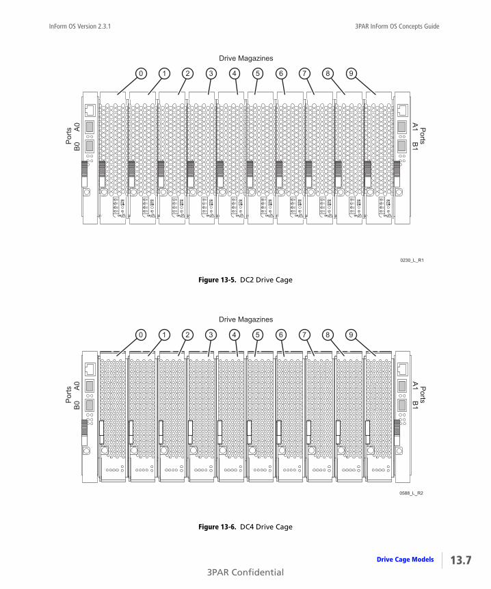
InForm OS Version 2.3.1 3PAR InForm OS Concepts Guide
Figure 13-5. DC2 Drive Cage
Figure 13-6. DC4 Drive Cage
0230_L_R1
Drive Magazines
B0
A0
Por
tsA
1B
1P
orts0 1 2 3 4 5 6 7 8 9
0588_L_R2
Drive Magazines
B0
A0
Por
tsA
1B
1P
orts
0 1 2 3 4 5 6 7 8 9
13.7Drive Cage Models
3PAR Confidential

13.8
3PAR InForm OS Concepts Guide InForm OS Version 2.3.1
13.4.2 DC2 and DC4 Ports and Cabling
The DC2 and DC4 drive cages contain two FCAL modules for connecting the drive cage to the
controller nodes. The left-hand FCAL module has two ports: A0 and B0, and the right-hand
FCAL module has two ports: A1, and B1.
Fibre Channel cables connect the Fibre Channel ports in the drive cage to the ports on the
controller nodes. Each cable is labeled to indicate the ports it uses (Figure 13-7):
Figure 13-7. Cable Labels for FCAL Module to Node Connections
NOTE: Daisy chaining is not supported for the DC2 or DC4 drive cages.
(Cxx.x) Nx:Sx:Px <–> (Cxx.x) Dx:Px
Cabinet and Bay(Node Chassis Cabinet)
Node Fibre ChannelAdapter Port
Cabinet and Bay(Drive Chassis Cabinet)
Drive Chassis DrivCage Port
NOTE: For detailed information about cabling and cable configurations, refer to
the InServ Storage Server Physical Planning Manual.
Drive Cage Models
3PAR Confidential

InForm OS Version 2.3.1 3PAR InForm OS Concepts Guide
13.4.3 DC3 Drive Cage
The DC3 drive cage contains 16 drive bays at the front, each accommodating the appropriate
plug-in drive magazine module. The 16 drive bays are arranged in four rows of four drives.
Figure 13-8 shows the front view of a DC3 drive cage.
Figure 13-8. DC3 Drive Cage (Front View)
13.4.4 DC3 Ports and Cabling
In the DC3 drive cage, two Switched Bunch of Disks (SBD) Modules, each providing four small
form-factor pluggable (SFP) modules to service the drive cage. The left-hand SBD has four
ports, labeled Port 0 through Port 3, from bottom to top. The right-hand SBD has four ports,
labeled Port 0 through Port 3, from top to bottom. Figure 13-9 shows the rear view of a DC3
drive cage.
Figure 13-9. DC3 Drive Cage (Rear View)
0148_L_R2
0401_L_R1
FCAL-B FCAL-A
B3B2B1B0
A0A1A2A3
Drive ChassisPower Supply 0
Drive ChassisPower Supply 1
13.9Drive Cage Models
3PAR Confidential
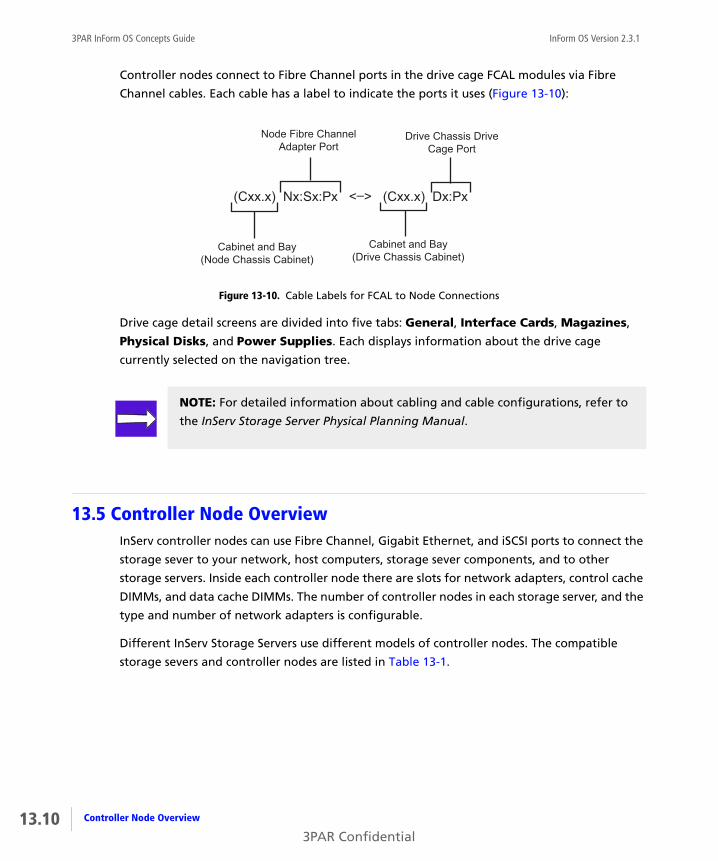
13.10
3PAR InForm OS Concepts Guide InForm OS Version 2.3.1
Controller nodes connect to Fibre Channel ports in the drive cage FCAL modules via Fibre
Channel cables. Each cable has a label to indicate the ports it uses (Figure 13-10):
Figure 13-10. Cable Labels for FCAL to Node Connections
Drive cage detail screens are divided into five tabs: General, Interface Cards, Magazines,
Physical Disks, and Power Supplies. Each displays information about the drive cage
currently selected on the navigation tree.
13.5 Controller Node OverviewInServ controller nodes can use Fibre Channel, Gigabit Ethernet, and iSCSI ports to connect the
storage sever to your network, host computers, storage sever components, and to other
storage servers. Inside each controller node there are slots for network adapters, control cache
DIMMs, and data cache DIMMs. The number of controller nodes in each storage server, and the
type and number of network adapters is configurable.
Different InServ Storage Servers use different models of controller nodes. The compatible
storage severs and controller nodes are listed in Table 13-1.
(Cxx.x) Nx:Sx:Px <–> (Cxx.x) Dx:Px
Cabinet and Bay(Node Chassis Cabinet)
Node Fibre ChannelAdapter Port
Cabinet and Bay(Drive Chassis Cabinet)
Drive Chassis DriveCage Port
NOTE: For detailed information about cabling and cable configurations, refer to
the InServ Storage Server Physical Planning Manual.
Controller Node Overview
3PAR Confidential

InForm OS Version 2.3.1 3PAR InForm OS Concepts Guide
The number of controller nodes each storage server model can accommodate is summarized in
Table 13-2.
The number of host ports each storage server model can accommodate is summarized in
Table 13-3.
Table 13-1. Storage Server and Controller Node Model Compatibility
Storage Server Model Controller Node Model
InServ S400 and S800 S-Class
InServ T400 and T800 T-Class
InServ E200 E-Class
InServ F200 and F400 F-Class
Table 13-2. Storage Server Models and Number of Controller Nodes
Storage Server Model Number of Controller Nodes
InServ S400 and T400 2 or 4
InServ S800 and T800 2, 4, 6, or 8
InServ E200 and F200 2
InServ F400 4
Table 13-3. Storage Server Models and Number of Ports
Storage Server Model Number of FC Ports Number of iSCSI Ports
InServ S400 and T400 0-64 0-16
InServ S800 and T800 0-128 0-32
13.11Controller Node Overview
3PAR Confidential

13.12
3PAR InForm OS Concepts Guide InForm OS Version 2.3.1
13.5.1 S-Class and T-Class Node Numbering
13.5.2 S-Class and T-Class Controller Node Numbering
InServ S-Class and T-Class Storage Servers have 2, 4, 6, or 8 controller nodes depending on the
storage server model. The controller nodes assume the number of the bay they occupy in the
storage server backplane. The bays are numbered from 0 to <n>, from left to right, and from
top to bottom. See Figure 13-11 for an example of controller node numbering in an InServ
T800 Storage Server fully populated with 8 controller nodes.
InServ E200 and F200 0-8 0-4
InServ F400 0-16 0-8
Table 13-3. Storage Server Models and Number of Ports
Storage Server Model Number of FC Ports Number of iSCSI Ports
NOTE: For detailed information about ports, network adapters, cabling, and
cable configurations, refer to the 3PAR InServ S-Class/T-Class Storage Server
Physical Planning Manual or the 3PAR InServ E-Class/F-Class Storage Server and
Third-Party Rack Physical Planning Manual.
NOTE: For information about port location and numbering, see Port Location
Formats on page 6.3 for more information.
NOTE: Refer to the InForm OS CLI Administrator’s Manual and InForm OS
Management Console Online Help for information about how to view the control
cache DIMM and data cache DIMM configuration for each controller node. For
information about memory expansion, contact your 3PAR representative.
Controller Node Overview
3PAR Confidential

InForm OS Version 2.3.1 3PAR InForm OS Concepts Guide
Figure 13-11. T800 Controller Node Numbering
NOTE: If an InServ T800 backplane contains only two controller nodes, the
controller nodes occupy the bottom 2 bays of the backplane enclosure and are
numbered controller node 6 and controller node 7.
0586_L_R1
1
3
5
7
0
2
4
6
13.13Controller Node Overview
3PAR Confidential

13.14
3PAR InForm OS Concepts Guide InForm OS Version 2.3.1
13.5.3 E-Class and F-Class Controller Node Numbering
InServ E-Class and F-Class Storage Servers have a different number of controller nodes
depending on the storage server model.
■ InServ E-Class Storage Servers always contain two controller nodes. The top controller node
is number 0 and the bottom controller node is number 1.
■ InServ F-Class Storage Servers contain two or four controller nodes. The controller nodes
are numbered 0-3 from top to bottom.
See Figure 13-12 for an example of controller node numbering in an InServ F400 Storage
Server with four controller nodes.
Figure 13-12. F400 Controller Node Numbering
0757_L_R1
0
1
2
3
Controller Node Overview
3PAR Confidential

InForm OS Version 2.3.1 3PAR InForm OS Concepts Guide
14SNMP
In this chapter
14.1 Overview 14.1
14.2 About SNMP 14.2
14.3 SNMP Managers 14.2
14.4 The 3PAR SNMP Agent 14.3
14.4.1 Standard Compliance 14.3
14.4.2 Supported MIBs 14.3
The purpose of this chapter is to provide information about using the 3PAR SNMP agent and
the SNMP interface.
14.1 OverviewIn addition to managing the InServ Storage Server with the InForm Management Console and
the InForm CLI, the 3PAR InForm OS includes an SNMP agent that allows you to perform some
basic management functions via network management software running on a management
station. These SNMP management functions require that you have SNMP management
software not provided by 3PAR.
14.1SNMP
3PAR Confidential

14.2
3PAR InForm OS Concepts Guide InForm OS Version 2.3.1
14.2 About SNMP Simple Network Management Protocol (SNMP) is a standard management interface used by
many software frameworks to manage hardware devices. Use of SNMP requires two
components, an agent and a manager. The manager is the management process that sends
requests to the agent. The host that the manager runs on is called the management station.
14.3 SNMP ManagersThere are four types of requests that an SNMP manager can send to an agent:
■ SET. The SET request writes an object value in the agent. The SET request includes the
object ID and a new value for the object. The agent will change the value of the object and
save it in the persistent store. Not all objects are changeable. The MIB contains access
information.
■ GET. The GET request reads an object value in the agent. The GET request includes the
object ID to be retrieved. The agent returns the value of the object.
■ GETNEXT. The GETNEXT request reads the object instance that is next in lexicographical
order to the object ID in the request. For example, if the object ID specified in the request is
.12925.0, the returned object ID should be .12925.1, if it exists.
■ GETBULK. The GETBULK operation is an optimization of the GETNEXT operation, that
allows multiple instances of objects to be returned.
In addition, the manager can register with the agent to receive notifications (traps) for critical
events (alerts) and alert state changes. These traps include the same information as the alerts
described in the 3PAR InForm OS Messages and Operator’s Guide, but they are in standard
SNMP format. Before an SNMP manager can receive the traps generated by the 3PAR SNMP
agent, you must register your manager with the agent. Refer to Chapter 14, Using SNMP, in the
InForm OS CLI Administrator’s Manual for instructions on registering an SNMP manager with
the 3PAR SNMP agent.
About SNMP
3PAR Confidential

InForm OS Version 2.3.1 3PAR InForm OS Concepts Guide
14.4 The 3PAR SNMP AgentThe 3PAR SNMP agent runs on the InServ Storage Server and provides a management interface
to enable other software products to manage 3PAR hardware using SNMP. The 3PAR SNMP
agent responds to GET, SET, GETNEXT, and GETBULK SNMP requests and also generates
notification messages (traps) for critical events (alerts) and alert state changes. The SNMP
agent converts all system alerts and alert state changes into SNMPv2 traps and forwards them
to all SNMP management stations that have previously registered with the agent. These
notifications contain detailed information describing critical events and are generated for
every alert and alert state change issued by the InServ Storage Server. The exact message
formats are described in the 3PAR MIB. See Chapter 14, Using SNMP, in the InForm OS CLI
Administrator’s Manual for instructions on locating this file.
14.4.1 Standard Compliance
The 3PAR SNMP agent supports the following standards:
■ SNMPv2c
This version refers to a widely used administrative framework for SNMPv2, also known as
“community-based SNMPv2.” Although this version includes SNMPv2 enhancements like
notification and GETBULK requests, it still relies on the SNMPv1 community concept for
security.
■ Standard Management Interface-v2 (SMIv2)
This standard specifies the format of the MIB. The 3PAR MIB definition uses SMIv2
conventions.
14.4.2 Supported MIBs
You can find the MIB files on the InForm CLI and SNMP CD. The 3PAR SNMP agent supports the
following MIBs:
■ SNMPv2-MIB
◆ Management Information Block-II (MIB-II), system group.
For discovery and basic information, the 3PAR SNMP agent supports the MIB-II system
group.
◆ snmpTrap group, snmpTrapOID only.
14.3The 3PAR SNMP Agent
3PAR Confidential
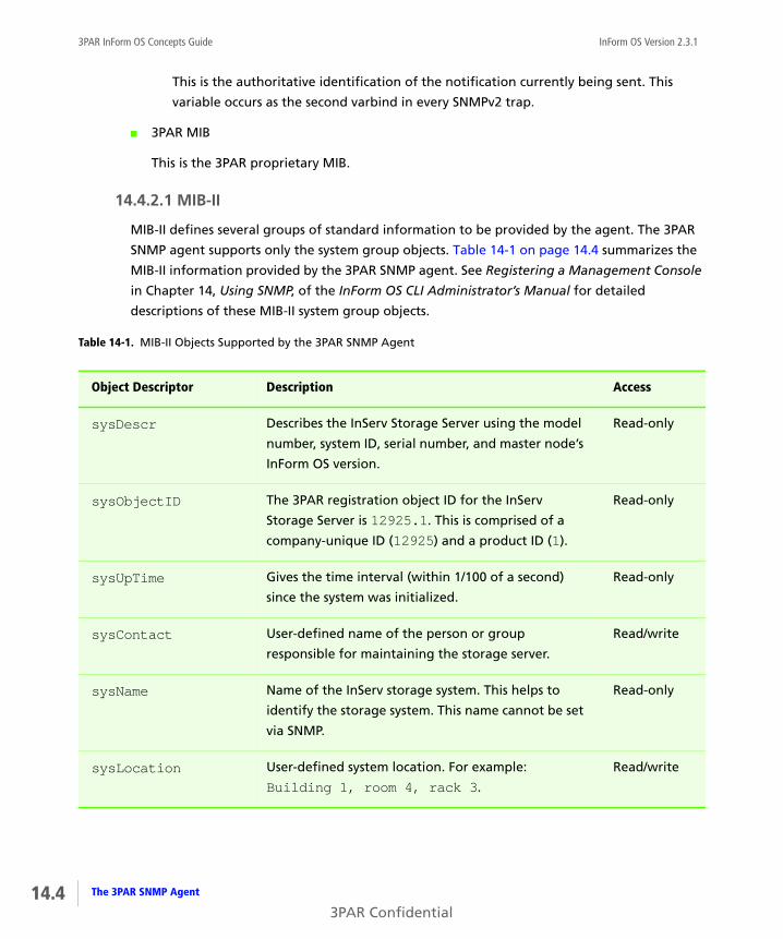
14.4
3PAR InForm OS Concepts Guide InForm OS Version 2.3.1
This is the authoritative identification of the notification currently being sent. This
variable occurs as the second varbind in every SNMPv2 trap.
■ 3PAR MIB
This is the 3PAR proprietary MIB.
14.4.2.1 MIB-II
MIB-II defines several groups of standard information to be provided by the agent. The 3PAR
SNMP agent supports only the system group objects. Table 14-1 on page 14.4 summarizes the
MIB-II information provided by the 3PAR SNMP agent. See Registering a Management Console
in Chapter 14, Using SNMP, of the InForm OS CLI Administrator’s Manual for detailed
descriptions of these MIB-II system group objects.
Table 14-1. MIB-II Objects Supported by the 3PAR SNMP Agent
Object Descriptor Description Access
sysDescr Describes the InServ Storage Server using the model
number, system ID, serial number, and master node’s
InForm OS version.
Read-only
sysObjectID The 3PAR registration object ID for the InServ
Storage Server is 12925.1. This is comprised of a
company-unique ID (12925) and a product ID (1).
Read-only
sysUpTime Gives the time interval (within 1/100 of a second)
since the system was initialized.
Read-only
sysContact User-defined name of the person or group
responsible for maintaining the storage server.
Read/write
sysName Name of the InServ storage system. This helps to
identify the storage system. This name cannot be set
via SNMP.
Read-only
sysLocation User-defined system location. For example:
Building 1, room 4, rack 3.
Read/write
The 3PAR SNMP Agent
3PAR Confidential
InForm OS Version 2.3.1 3PAR InForm OS Concepts Guide
14.4.2.2 Exposed Objects
The 3AR SNMP agent supports MIB-II system group objects. This section describes each of those
objects in detail.
14.4.2.2.1 System Description
Access: Read-only
MIB definition: sysDescrData type: Display string (max. 255 characters)
Default value: 3PAR InServDescription: Identifies InServ Storage Server model, system ID, serial number and InForm OS
version of the master node. For example, if the system has four nodes, the sysDescr may
resemble the following:
3PAR InServT400, serial number 876541, InForm OS version 2.2.4. This is only
a brief system description. Use the InForm CLI to obtain further details about the system and
each node. This is a read-only attribute.
14.4.2.2.2 System Object ID
Access: Read-only
MIB definition: sysObjectIDData type: integer
Default value: 12925.1Description: Identifies the unique product ID for the 3PAR InServ Storage Server. The first part
of this ID is the unique enterprise ID assigned to 3PAR, Inc. by ICANN (12925). The second part
of this ID is the product ID assigned to the InServ Storage Server (1). If there are future
products other than the InServ, they will be assigned incremental integers (2, 3, and so on).
The manager uses this ID to identify products manufactured by 3PAR. This is a read-only
attribute.
14.4.2.2.3 System Up Time
Access: Read-only
MIB definition: sysUpTimeData type: time-tick (1/100 second)
Default value: 0Description: Indicates how long the system has been operational, beginning with system
initialization. This is a read-only attribute.
14.5The 3PAR SNMP Agent
3PAR Confidential

14.6
3PAR InForm OS Concepts Guide InForm OS Version 2.3.1
14.4.2.2.4 System Contact Information
Access: Read/write
MIB definition: sysContactData type: Display string (max. 255 characters)
Default value: Please provide contact information such as name, phone number, and e-mail addressDescription: Specifies the name of a person or group responsible for maintaining the InServ
storage system. This value can be changed via the manager at any time.
14.4.2.2.5 System Name
Access: Read-only
MIB definition: sysNameData type: Display string (max. 255 characters)
Default value: None
Description: Indicates the system name, which is set during initialization and setup of the
system. This helps to identify this InServ storage system from other systems. The value cannot
be changed by the manager.
14.4.2.2.6 System Location
Access: Read/write
MIB definition: sysLocationData type: Display string (max. 255 characters)
Default value: Please provide location description where the device resides such as building, room, and rack numberDescription: Contains the user-defined location of the system. This helps to indicate where
the storage system is located. For example, the location may be indicated as follows:
Building 1, room 4, rack 3. This value can be changed via the manager at any time.
14.4.2.3 The 3PAR MIB
The 3PAR MIB contains proprietary information that reflects the configuration and behavior of
the InServ storage system and may be useful for network management. Currently, the 3PAR
MIB only contains the alertNotify trap definition. Table 14-2 on page 14.7 summarizes the
contents of this trap.
The 3PAR SNMP Agent
3PAR Confidential

InForm OS Version 2.3.1 3PAR InForm OS Concepts Guide
Table 14-2. Contents of the alertNotify trap
Object Descriptor Description Access
component Tells you which system hardware, software, or logical
component caused the alert or alert state change.
Read-only
details Detailed description of the alert or alert state
change, displayed as an alert string (for example: PR table <table_name> is corrupt). See the
InForm OS Messages and Operator’s Guide for exact
content of all possible alert strings. See alertNotify
Traps on page 14.8 for the exact content of the alert
state change notification string.
Read-only
nodeID Node identification number, an integer from 0
through 7 that indicates which storage server
controller node reported the alert or alert state
change.
Read-only
severity Severity level of the alert or alert state change, which
is an integer from 0 to 5. See the 3PAR MIB for
definitions for each integer.
Read-only
timeOccurred Time the alert or alert state change occurred, in
DDD mmm dd hh:mm:ss ZZZ yyyy format (for
example: Mon, Jan 01 12:30:34 PST 2005).
Read-only
id Alert ID. The alert ID uniquely identifies an
outstanding alert on some object within the InServ
Storage Server. Alert IDs are automatically generated
by the InForm OS and increment when a new alert on
a new object is detected. Note also that if an alert is
generated on an object and alerts already exist in the
system, the alert ID is removed. For alert state traps,
the alert ID will be the same as the ID of the trap that
indicated the original problem.
Read-only
14.7The 3PAR SNMP Agent
3PAR Confidential

14.8
3PAR InForm OS Concepts Guide InForm OS Version 2.3.1
14.4.2.3.1 alertNotify Traps
An alertNotify trap contains details about an event that may affect system operations and
performance. All alerts generated by the system as well as all alert status change events are
translated into alertNotify traps.
The following example shows an alertNotify trap translated from an alert:
For this and for all alerts, use the message code provided (e.g., 1703938) to refer to the InForm
OS Messages and Operator’s Guide for instructions regarding required operator actions
pertaining to the alert.
messageCode Code that identifies the specific type of alert or alert
state change. For example, the message code for the
alert state change is 1245186. For alerts, use the
message code in referring to the InForm OS Messages
and Operator’s Guide for instructions on prescribed
operator actions.
Read-only
state Current alert state, which is an integer between 0
and 5. See the 3PAR MIB for definitions for each
integer. Alert states enable users to maintain detailed
tracking of alerts throughout their life cycle.
Read-only
Table 14-2. Contents of the alertNotify trap (continued)
Object Descriptor Description Access
sysUpTime.0:0 hours, 28 minutes, 1 seconds. snmpTrapOID.0:.iso.org.dod.internet.private.enterprises.threepar.inserv.alertNotifycomponent.1:comp_hw_nodedetails.1:Node 7 is offlinenodeID.1:0severity.1:major(2)timeOccurred.1:Wed Dec 15 16:58:20 PST 2004id.1:647messageCode.1:1703938state.1:new(1)
The 3PAR SNMP Agent
3PAR Confidential

InForm OS Version 2.3.1 3PAR InForm OS Concepts Guide
An alert status change event is not an alert. It notifies you that an alert has changed status
(e.g., from New to Resolved by System). The following example shows an alertNotify trap
translated from an alert status change event:
The following information describes these alert status change events:
Message Code
1245186
Severity
Info
Type
Change in alert state
Alert String
Alert <alert_id> changed from state <old_state> to <new_state>
Operator Action
The alert has changed state. This can be used to track the state of the existing alerts in an
InServ Storage Server.
NOTE: If you receive a trap with messageCode == 1245186, this is to notify you
that an alert has changed state. In order to find out which alert has changed
state, you must extract the alert ID from the id trap field.
sysUpTime.0:0 hours, 5 minutes, 26 seconds. snmpTrapOID.0:.iso.org.dod.internet.private.enterprises.threepar.inserv.alertNotifycomponent.1:comp_sw_alertdetails.1:Alert 647 changed from state New to Resolved by SystemnodeID.1:1severity.1:info(5)timeOccurred.1:Thu Dec 16 14:06:36 PST 2004id.1:647messageCode.1:1245186state.1:autofixed(5)
14.9The 3PAR SNMP Agent
3PAR Confidential

14.10
3PAR InForm OS Concepts Guide InForm OS Version 2.3.1
The 3PAR SNMP Agent
3PAR Confidential

InForm OS Version 2.3.1 3PAR InForm OS Concepts Guide
15The 3PAR InForm CIM API
In this chapter
15.1 Overview 15.2
15.2 About SMI-S 15.2
15.3 About the WBEM Initiative 15.3
15.4 3PAR InForm CIM Support 15.4
15.4.1 Standard Compliance 15.4
15.4.2 SMI-S Profiles 15.4
15.4.3 Supported Extensions 15.4
15.4.4 CIM Indications 15.4
The purpose of this chapter is to provide an overview of the 3PAR InForm CIM application
programming interface (API).
15.1The 3PAR InForm CIM API
3PAR Confidential

15.2
3PAR InForm OS Concepts Guide InForm OS Version 2.3.1
15.1 OverviewThis chapter describes the 3PAR InForm CIM Application Programming Interface (API), 3PAR’s
industry-standard API based on SNIA’s Storage Management Initiative Specification (SMI-S). For
detailed information about the 3PAR InForm CIM API, refer to the 3PAR CIM API Programming
Reference.
15.2 About SMI-SSMI-S enables management of storage area networks (SANs) in a heterogeneous multi-vendor
environment. SMI-S uses an object-oriented model based on the Common Information Model
(CIM) to define objects and services which comprise a SAN. By leveraging vendor and
technology independent standards, SMI-S allows management application vendors to create
applications that work across products from multiple vendors.
The SMI-S model is divided into several profiles, each of which describes a particular class of
SAN entities (such as disk arrays). These profiles allow for differences in implementations but
provide a consistent approach for clients to discover and manage SAN resources and facilitate
interoperability across vendor products within the SAN.
SMI-S also defines an automated resource discovery process using Service Location Protocol
version 2 (SLPv2). This allows management applications to automatically find SAN resources
and then probe them to determine which of the SMI-S profiles and features they support.
For more information about SMI-S, refer to the Storage Management Initiative web site at
http://www.snia.org/smi/home.
Overview
3PAR Confidential
InForm OS Version 2.3.1 3PAR InForm OS Concepts Guide
15.3 About the WBEM InitiativeSMI-S is based on the Web-Based Enterprise Management (WBEM) Initiative, which is defined
by the Distributed Management Task Force (DMTF). WBEM is a set of management and
Internet standard technologies developed to unify the management of distributed computing
environments.
The DMTF has developed a core set of standards that make up WBEM:
■ The Common Information Model (CIM) standard
The CIM standard is the data model for WBEM. CIM provides a conceptual framework for
describing management data for systems, networks, applications and services, and allows
for vendor extensions. SMI-S uses CIM to model those objects and relationships that
comprise a SAN.
■ CIM-XML
CIM-XML is a method of exchanging CIM management data. CIM-XML uses an xmlCIM
payload and HTTP(s) as the transport mechanism.
This protocol is defined by the following specifications:
◆ Specification for the Representation of CIM in XML
Defines a standard for the representation of CIM elements and messages in XML,
written in Document Type Definition (DTD).
◆ CIM Operations over HTTP
Defines a mapping of CIM Messages onto HTTP that allows implementations of CIM to
interoperate in an open, standardized manner. It uses the CIM XML DTD that defines
the XML Schema for CIM objects and messages.
■ WBEM Discovery using Service Location Protocol (SLP)
WBEM Discovery using SLP is a method for applications to identify WBEM-based
management systems.
For more information regarding WBEM and CIM, please refer to the DMTF web site at
http://www.dmtf.org.
15.3About the WBEM Initiative
3PAR Confidential
15.4
3PAR InForm OS Concepts Guide InForm OS Version 2.3.1
15.4 3PAR InForm CIM SupportThe following sections provide information about the 3PAR InForm CIM API provided with
InForm OS Version 2.3.1.
15.4.1 Standard Compliance
■ The 3PAR InForm CIM Server supports SMI-S version 1.1.0.
■ The 3PAR InForm CIM API passes SNIA-CTP conformance. For additional information, see
http://www.snia.org.
15.4.2 SMI-S Profiles
SMI-S defines a number of profiles that are used to manage elements of a SAN. These SMI-S
Profiles are described in detail in the 3PAR CIM API Programming Reference.
15.4.3 Supported Extensions
The 3PAR InForm CIM Server supports additional classes that provide management for InServ
Storage Server specific features not covered by SMI-S. Refer to the 3PAR CIM API Programming
Reference for complete information.
15.4.4 CIM Indications
SMI-S provides for asynchronous notification of events that indicate changes in the CIM server
or the managed elements controlled by the CIM server. CIM Indications are the mechanism for
delivery of such events. A CIM client must subscribe to indications that it wants to receive the
event notifications from the CIM server. For detailed information regarding Indications, refer
to SMI-S at http://www.snia.org.
The 3PAR InForm CIM Server currently supports indication subscriptions for changes in the
operational status of fibre channel ports. Refer to the 3PAR CIM API Programming Reference
for complete information.
3PAR InForm CIM Support
3PAR Confidential

InForm OS Version 2.3.1 3PAR InForm OS Concepts Guide
Glossary
3PAR Virtual Domains
A 3PAR feature that is used to create distinct
domains with domain-specific users and objects
in an InServ Storage Server.
3PAR Recovery Manager
A 3PAR data protection solution that has been
enhanced to provide fast and efficient Oracle
and SQL Server backups and restores.
3PAR Remote Copy
The 3PAR product used to create remote copies
of virtual volumes.
3PAR System Tuner
The 3PAR utility used to identify overused
chunklets and perform load balancing.
3PAR Thin Provisioning
A 3PAR product that allows the user to allocate
only the physical resources that are actually
needed while presenting an arbitrarily large
volume that can have its physical resources
allocated on demand.
3PAR Virtual Copy
The 3PAR product used to create copy-on-write
snapshots (virtual copies) of virtual volumes.
AAccess Guard
3PAR software component that provides volume
security at logical and physical levels. Access
Guard is part of the InForm Software Suite.
active VLUN
The connection of a virtual volume and a LUN for
a particular host on a particular port. An active
VLUN is created when a VLUN template is
applied to the current system state. See also
VLUN template.
admin space
See snapshot administration space.
admin volume
The base volume that is used by the system to
store administration data such as the system
event log. The admin volume is created as part of
the storage server installation and setup process.
administration space
See snapshot administration space.
AL_PA
See arbitrated loop physical address.
GL 1Glossary
3PAR Confidential
GL 2
InForm OS Version 2.3.1 3PAR InForm OS Concepts Guide
alert
An alert is a system event that requires the
immediate attention of the user, and may also
require user intervention. See also event.
alert pane
The alert pane, located at the bottom of the
InForm Management Console main window,
displays information about system alerts.
allocation limit
User-defined threshold that can be set for Thinly-
Provisioned Virtual Volumes (TPVVs) and fully-
provisioned virtual volumes to cap their
potential size. See also allocation warning.
allocation warning
User-defined threshold that can be set for Thinly-
Provisioned Virtual Volumes (TPVVs) and fully-
provisioned virtual volumes to alert users when
they reach a certain size. See also allocation
limit.
arbitrated loop physical address (AL_PA)
A unique 8-bit value used to identify Fibre
Channel devices on an arbitrated loop.
availability
Level of fault tolerance for a logical disk. For
example, Magazine level availability means that
the logical disk can tolerate a drive magazine
failure. Cage availability level means that the
logical disk can tolerate a drive cage failure.
Bbackup node
See virtual volume backup node.
base volume
A Thinly-Provisioned Virtual Volume (TPVV) or
fully-provisioned virtual volume that has been
copied. See also Thinly-Provisioned Virtual
Volumes (TPVVs) and fully-provisioned virtual
volumes.
battery backup unit (BBU)
A unit containing two batteries. Each battery
backup unit supplies two controller nodes with
enough current to write the cache to ATA disks
in the event of a power interruption.
battery tray
An enclosure that inserts into an EIA-standard
rack to house a maximum of four battery backup
units.
BBU
See battery backup unit.
Ccabinet
An enclosure that houses the components of a
storage server. A cabinet is made up of a frame
on four wheels, cosmetic panels, a rear door, an
EIA-standard rack, PDUs, power cords, and
bezels.
cache memory page (CMP)
A 16-KB block of control cache memory where
I/O requests are stored.
cage
See drive cage.
child volume
A virtual volume (virtual or physical copy) made
from a parent volume.
chunklet
A 256-MB block of contiguous space on a
physical disk.
chunklet logging
An action by the system that occurs when a
chunklet is unavailable (for example, the disk is
Glossary
3PAR Confidential

InForm OS Version 2.3.1 3PAR InForm OS Concepts Guide
not ready). The chunklet is placed in logging
mode, where data that is supposed to be written
to the chunklet is instead written to a log. If the
chunklet becomes available again, the system
places the chunklet in playback mode, where the
data is read from the log and written to the
appropriate chunklet.
classes of service
The characteristics and guarantees of the
transport layer of a Fibre Channel circuit. These
classes include connection services (Class 1),
guaranteed frame delivery with end-to-end flow
control (Class 2), and packetized frame
datagrams (Class 3).
clean chunklet
A chunklet that is set to all zeros, and therefore
does not contain any data.
cluster
A group of controller nodes connected via the
same storage server backplane. The nodes in a
cluster operate as a unified system, separate
from any other clusters that may share the same
service processor.
CMP
See cache memory page.
Common Provisioning Group (CPG)
A set of logical disks from which you can create
virtual volumes and virtual copies that are
capable of allocating storage on demand.
component indicator
InForm Management Console alert pane icon
that represents a logical or physical storage
server component. See also alert pane.
control cache
Memory modules that support the
microprocessors located in a controller node.
control cache DIMM
A single control cache memory module.
controller node
An individual device that works together with
other controller nodes to cache and manage
data in a storage server and to provide hosts
with a coherent, virtualized view of the storage.
controller node chassis
An enclosure that houses all the controller nodes
of a storage server.
copy-on-write snapshot
A snapshot of a virtual volume made with the
copy-on-write technique. Consists of a pointer to
the source volume and a record of every change
made to the source volume since the snapshot
was created.
fully-provisioned virtual volume
A virtual volume with a set amount of user space
and whose snapshot administration space and
snapshot data space draw from a Common
Provisioning Group (CPG).
copy data
Data that occupies the snapshot data space on a
virtual volume. See also snapshot data space.
copy size
The size of the snapshot data space in a virtual
volume, which is the amount of logical disk
space reserved for snapshots. See also snapshot
data space.
copy space
See snapshot data space.
GL 3Glossary
3PAR Confidential

GL 4
InForm OS Version 2.3.1 3PAR InForm OS Concepts Guide
CPG template
Common provisioning group template. The
template contains a set of common provisioning
group and logical disk parameters that can be
applied again and again to create common
provisioning groups with the same characteristics
using the InForm Management Console.
created host
A host that has been defined on the system but
does not necessarily have any physically
connected host paths or WWNs assigned to it.
Customer Controlled Access
A software tool that restricts connections
between the service processor and the 3PAR
technical support center. Customer Controlled
Access is independent of the user’s network
firewall and works whether the connections are
made via the Internet or via a point-to-point
modem connection.
Ddaisy chaining
Cabling configuration where components such
as BBUs or drive cages are connected in
succession.
data cache
The dual in-line memory modules (DIMMs) that
support the 3PAR ASIC located in a controller
node.
data cache DIMM
A single data cache memory module.
data cache riser card
A printed circuit board with DIMM sockets that
holds data cache memory modules.
DC2 drive cage
One of two models of a storage server
component consisting of a drive cage midplane,
two drive cage FCAL modules, four power
supplies, and up to 40 physical disks in a
maximum of ten drive magazines.
DC3 drive cage
A storage server component that consists of a
drive cage, two drive cage FCAL modules, two
power supplies, and up to 16 physical disks.
DC4 drive cage
One of two models of a storage server
component consisting of a drive cage midplane,
two drive cage FCAL modules, four power
supplies, and up to 40 physical disks in a
maximum of ten drive magazines.
destination volume
The virtual volume to which data is copied
during a physical copy operation.
disk port
See initiator port.
disk scrub
An action by the system that periodically reads
and writes to the system IDE disk to ensure that
the disk is working properly.
dmag
See drive magazine.
drive bay
A space in a drive chassis into which a drive
magazine is inserted.
drive cage
See DC2, DC3, and DC4 drive cage.
Glossary
3PAR Confidential

InForm OS Version 2.3.1 3PAR InForm OS Concepts Guide
drive cage FCAL module
An interface module, located in a drive chassis,
connecting a drive cage to a controller node or
to another drive cage.
drive chassis
Enclosure that takes up 4U of an EIA-standard
rack, used for housing the drive cage(s).
drive chassis cabinet
In a multi-cabinet storage server, any cabinet
that is connected to a node cabinet but does not
contain controller nodes.
drive chassis housing
The enclosure that houses the components of a
drive chassis.
drive magazine
An electronic circuit board mounted on a
mechanical structure that is inserted into a drive
bay in a drive cage. A drive magazine holds up to
four physical disks.
drive magazine filler panel
A panel used to seal off an empty drive bay. All
slots in a drive cage must be sealed for EMI and
airflow considerations.
drive mount
A metal bracket used to secure a physical disk to
a drive magazine. Each disk requires two drive
mounts.
Eenclosure services interface
Interface on the DC2 and DC4 drive cages
through which the node software communicates
to the cage enclosure services controller to
obtain status and control the cage behaviors.
event
A normal system occurrence.
ESI
See enclosure services interface.
export
To make a virtual volume available to a
particular instance of a host (that is, a host WWN
that is actually present on a port) by creating an
association between the name of the virtual
volume and a LUN for that host on that port. See
also LUN, VLUN, and VLUN template.
FFCAL
Stands for Fibre Channel-Arbitrated Loop. FCAL
is a fast serial bus interface standard used to
connect storage devices to servers.
FCAL module
See drive cage FCAL module.
Fibre Channel adapter
A Fibre Channel PCI host bus adapter (HBA)
located in a controller node. The Fibre Channel
adapter connects a controller node to a host or
to a drive chassis.
filtering
In the InForm Management Console, filtering a
table temporarily removes table entries that do
not meet the specified criteria. See also selecting.
GGigabit Ethernet adapter
A network adapter located in a controller node.
The Gigabit Ethernet adapter connects a
controller node to a network for the purpose of
GL 5Glossary
3PAR Confidential

GL 6
InForm OS Version 2.3.1 3PAR InForm OS Concepts Guide
transferring data via the network. See also 3PAR
Remote Copy.
grow
To expand a base volume manually by increasing
the user space, snapshot administration space, or
snapshot data space.
growth increment
The unit of storage by which additional logical
disks are created and allocated to a Common
Provisioning Group (CPG). The growth increment
is used to automatically create and allocate space
on demand as additional resources are required
by the volumes that draw from the logical disk
pool. The default growth increment is fixed at 32
GB, but the minimum growth increment varies
according to the number of controller nodes in
the system (from 8 GB for a two-node system to
32 GB for a four-node system). See Table 9-1 on
page 9.4 for details.
growth limit
User-defined threshold that can be set for
Common Provisioning Groups (CPGs) to cap their
potential size. See also growth warning.
growth warning
User-defined threshold that can be set for
Common Provisioning Groups (CPGs) to alert
users when they reach a certain size. See also
growth limit.
Hhost
A set of WWNs of the physical ports on a server.
host-sees VLUN template
A VLUN template that allows a particular host
connected to any port to see a virtual volume as
a specified LUN. See also VLUN template.
host definition
The name of the host plus a list of the WWNs
that make up the host. A host can have a host
definition even though it is not physically
connected to a storage server.
host port
See target port.
host-sees VLUN template
A rule that allows a particular host connected to
any port to see a virtual volume as a specified
LUN.
IIMP (Initiator Mode Prohibited)
This is a system setting. When IMP is enabled, a
port cannot be set to initiator mode. See also
initiator mode.
independent electrical circuit
An electrical circuit that does not share a circuit
breaker with another electrical circuit.
initiator, initiator port
A port that is connected to a drive cage. Also
known as a disk port because it sends commands
to the physical disks.
initiator mode
The firmware setting for a port that is connected
to a drive cage.
iSCSI adapter
An iSCSI PCI host bus adapter (HBA) located in a
controller node. The iSCSI adapter connects a
controller node to a host.
iSCSI name
A value used to identify iSCSI channel devices on
an arbitrated loop.
Glossary
3PAR Confidential

InForm OS Version 2.3.1 3PAR InForm OS Concepts Guide
LLD
See logical disk.
LD template
Logical disk template. The template contains a
set of logical disk parameters that can be applied
again and again to create logical disks or
volumes with the same characteristics using the
InForm Management Console.
LIP
See loop initialization primitive.
logging
Temporary use of logical disks to store data
during physical disk replacement procedures.
Each controller node has a 20 GB logging logical
disk.
logging LD
Logging logical disk. A RAID 10 logical disk
created during initial system setup and used to
temporarily store data during physical disk
failures and replacement procedures. Each
controller node has a 20 GB logging logical disk.
logical disk
An arrangement of rows of RAID sets. Logical
disks are mapped to virtual volumes.
logical disk backup node
The controller node that takes over for the
logical disk owner node if the logical disk owner
node fails.
logical disk owner node
The controller node that coordinates all transfers
to and from a logical disk, maintains the
mapping information, and coordinates the
recovery of failed physical disks.
logical disk pool
See Common Provisioning Group.
logical unit number
See LUN.
loop initialization primitive (LIP)
The protocol by which a Fibre Channel
Arbitrated Loop (FCAL) network initializes upon
power up or recovers after a failure or other
unexpected condition. During loop initialization,
the nodes present on the arbitrated loop identify
themselves and acquire addresses on the loop.
No data can be transferred on an arbitrated loop
until initialization completes.
LUN
Stands for logical unit number. A number used to
access a virtual volume that has been assigned to
a particular host on a particular port. See also
export, VLUN, and VLUN template.
magazine, mag
See drive magazine.
maintenance PC
A laptop computer running Windows 2000 used
by a field technician to initiate direct
communication with the storage server service
processor and controller nodes.
mapped, mapping
The correspondence of one element in the
system to another element.
master node
See virtual volume master node.
matched-set VLUN template
A rule that allows a particular host connected to
a particular port to see a virtual volume as a
specified LUN. See also VLUN template.
GL 7Glossary
3PAR Confidential
GL 8
InForm OS Version 2.3.1 3PAR InForm OS Concepts Guide
message code
A keycode that identifies a system alert.
midplane
See storage server backplane.
mirror
One member of a group of mirrored chunklets,
which is also known as a RAID 1 set.
mirror depth
See set size.
mirroring
A data redundancy technique used by some RAID
levels and in particular RAID 1 to provide data
protection on a storage array.
Nnavigation tree
The navigation tree appears in a pane that
occupies the left side of the InForm Management
Console main window. Each system and system
object appears as an icon in the navigation tree.
no stale snapshots
Virtual copy policy that prevents changes being
written to a base volume when it does not have
enough snapshot data or administration space to
prevent virtual copies from becoming invalid, or
stale, as a result. See also stale snapshots, virtual
copy policy.
node
See controller node.
node cabinet
A cabinet that houses the storage server
backplane and controller nodes.
node chassis
See controller node chassis.
Ooriginal parent base volume
The original base volume from which a series of
virtual and/or physical copies has been created.
Any volume can be the parent from which one or
more virtual copies is created, but for each set of
related copies there is only one original parent
base volume.
owner, owner node
See logical disk owner node.
Pparent volume
A virtual volume from which a virtual or physical
copy is made. See also original parent base
volume.
parity
A data redundancy technique used by some RAID
levels and in particular RAID 5 to provide data
protection on a storage array.
parity set
See RAID 5 set.
parity set position
The group of chunklets that occupy the same
position within a RAID 5 logical disk parity set.
PCI load card
An electronic circuit board that is inserted into a
controller node’s PCI slot. The PCI load card
allows the node to recognize an unoccupied PCI
slot.
PDU
See power distribution unit.
physical copy
A point-in-time copy of an entire virtual volume.
Glossary
3PAR Confidential

InForm OS Version 2.3.1 3PAR InForm OS Concepts Guide
physical copy resynch
See resynchronize.
physical disk
A dual-ported Fibre Channel disk mounted onto
a drive magazine.
physical parent
The source volume for a physical copy.
physical size
The total actual raw storage currently allocated
to a logical disk, as determined by its size and
raid type.
port-presents VLUN template
A VLUN template that allows any host connected
to a particular port to see a virtual volume as a
specified LUN. See also VLUN template.
power bank
A group of four connected AC outlets within the
power distribution unit (PDU). There are two
power banks in each PDU.
power distribution unit (PDU)
A device that takes in AC power from a main
power source (for example, an electrical wall
outlet) and distributes the power to the power
supplies in a storage server.
power supply
A device that converts current from an AC line
into appropriate DC levels and provides that
power to a storage server component.
preserved data
Data that is suspended in the system’s cache
memory due to backend failure.
preserved data logical disks
RAID 10 logical disks created by the system
during initial system setup to store preserved
data. The logical capacity of the preserved data
logical disks is equal to the sum of all data cache
memory of the system.
primary path
Connection between a controller node initiator
port and a physical disk that is used by default.
When the primary path cannot be used (a failure
condition), the secondary path is used. The
primary and secondary paths are not user
configurable and are determined by drive
magazine placement.
privilege levels
Four user privilege levels (Super, Edit, Service,
and Browse) allow varying degrees of access to
storage system administrative functions.
promote
For physical copies: to break the association
between a physical copy and a base volume by
changing the physical copy into an independent
base volume. For virtual copies: to copy the
changes from a virtual copy back onto the base
volume, therefore overwriting the base volume
with the virtual copy.
Rrack
The EIA-standard rack within a cabinet that
holds the components of a storage server.
rack filler panel
A panel used to seal off an empty 1U, 2U, or 4U
space on the rack. All empty spaces in the rack
must be sealed for EMI and airflow
considerations.
GL 9Glossary
3PAR Confidential

GL 10
InForm OS Version 2.3.1 3PAR InForm OS Concepts Guide
rack unit (U)
The standard unit of height for an EIA-standard
rack or components housed in an EIA-standard
rack: equivalent to 1.75 in. (4.45 cm).
RAID
Stands for redundant array of independent disks.
RAID 0 set
Striped rows of chunklets on two or more
physical disks. A RAID 0 set offers no data
redundancy.
RAID 10 (RAID 1) set
A group of mirrored chunklets.
RAID 50 (RAID 5) set
A group of parity-protected chunklets. Also
known as a parity set.
RAID Multi-Parity (MP)
A group of double-parity chunklets.
RAID set
A grouping of mirrored or parity-protected
chunklets.
RAID type
RAID 0, RAID 10 (1), RAID 50 (5), and RAID MP
(6)are all supported RAID types. However, not all
RAID types may be available on your system.
RCFC
Remote Copy over Fibre Channel. The use of
3PAR Remote Copy with two storage servers that
are connected via Fibre Channel ports. See also
3PAR Remote Copy.
RCIP
Remote Copy over IP. The use of 3PAR Remote
Copy with two storage servers that are
connected via Ethernet ports. See also 3PAR
Remote Copy.
region
A subdivision of a logical disk or virtual volume.
The size of a region is always a multiple of 32
MB.
registered state change notification (RSCN)
A Fibre Channel switch function that allows
notification to registered nodes if a change
occurs to other specified nodes.
registration
See iSCSI reservation/registration.
reservation
See iSCSI reservation/registration.
resynch, resynchronize
To copy changes from one volume in a physical
copy pair to the other because that volume was
modified at some point after the physical copy
operation took place. See also physical copy.
rollback
See promote.
row
A grouping of RAID sets. Data is striped across
the rows of RAID 10 and RAID 50 logical disks.
row size
The number of sets in a row. A row is a grouping
of RAID sets. Data is striped across the rows of
RAID 10 and RAID 50 logical disks.
RSCN
See registered state change notification.
SiSCSI reservation/registration
Allows multiple hosts to share a iSCSI interface to
access exported volumes. Multiple hosts can have
registrations to a single volume, but only one
host can have the reservation.
Glossary
3PAR Confidential

InForm OS Version 2.3.1 3PAR InForm OS Concepts Guide
safety breaker
The device used to power on and power off the
power distribution unit. The safety breaker also
prevents power surges in the AC line from
damaging a storage server.
second virtual volume backup node
The controller node that takes over for the
virtual volume backup node if the virtual volume
node fails.
secondary path
Connection between a controller node initiator
port and a physical disk that is used when the
primary path is inaccessible (a failure condition).
The primary and secondary paths are not user
configurable and are determined by drive
magazine placement.
selecting
In the InForm Management Console, Selecting
table entries highlights only the table entries
that meet the specified criteria. See also filtering.
service processor
A device inserted into a rack that enables 3PAR
service personnel to locally and remotely
monitor and service 3PAR Storage Servers.
set
See RAID set.
set size
The number of chunklets in a set. Also known as
mirror depth for RAID 1 sets and parity set for
RAID 5 sets.
severity indicator
Icon in the InForm Management Console alert
pane or on the InForm Management Console
status bar that shows the seriousness of an alert.
See also alert pane and status bar.
SFP
See small form-factor pluggable transceiver.
snapshot
A virtual or physical copy of a virtual volume.
snapshot administration space
The space on a virtual volume that is used to
track changes to the data since a snapshot of a
virtual volume was created.
source volume
The virtual volume from which a copy is made.
spare status
Indicates whether a chunklet is reserved as a
spare or has been selected by the system for use
in sparing on a temporary basis.
spare, spare chunklet
A chunklet that is reserved for use in case of a
failure in the system. A certain number of
chunklets are reserved for use as spares during
the system setup and installation process.
However, the system may temporarily set aside
additional spares even though these chunklets
are not permanently designated for use as
spares.
sparing
The automatic relocation of chunklets on a
physical disk when a logging logical disk
becomes full. See also spare chunklets.
stale data
Snapshot data that is no longer valid because the
base volume did not have enough snapshot
administration and/or snapshot data space to
record new changes to that base volume.
stale snapshot
A snapshot that does not track the most recent
changes to its base volume. The No Stale
GL 11Glossary
3PAR Confidential

GL 12
InForm OS Version 2.3.1 3PAR InForm OS Concepts Guide
Snapshots virtual copy policy halts writing data
to the base volume so as to prevent loss of sync
between the volume and any snapshots. See also
virtual copy policy and no stale snapshots.
started virtual volume
A virtual volume that either passed auto-check
upon system startup or was created since the
system was last restarted. Started virtual volumes
are ready for read/write operations.
status bar
The bar at the bottom of the InForm
Management Console main window that
contains messages and icons. Status bar
messages and icons can provide vital information
about system status, including the severity level
of the most serious new alert in the alert pane.
See also alert pane.
step size
The number of contiguous bytes that the system
accesses before moving to the next chunklet.
stopped virtual volume
A virtual volume that has not been started and is
therefore not ready for read/write operations.
storage server backplane
An electronic circuit board that contains sockets
into which power supplies and controller nodes
are plugged.
system box
Feature on the InForm Management Console
main window toolbar that enables you to move
quickly between systems.
system manager
Software component that negotiates between
the storage server and the user interfaces such as
the InForm Management Console and InForm
CLI.
system view pane
The system view pane occupies the upper right
corner of the InForm Management Console main
window and displays information about systems
and system objects as you select the
corresponding icons in the navigation tree. See
also navigation tree.
Ttable of contents (TOC)
The space on a physical disk that contains the
internal description of the system. The TOCs on
all physical disks in the system contain the same
information.
target, target port
The port that is connected to and receives
commands from a host computer. Also known as
a host port.
target mode
The firmware setting for a port that is connected
to a host.
Target Session Identifying Handle
An identifier, assigned by the iSCSI target, for a
session with a specific named initiator.
thin provisioning
See 3PAR Thin Provisioning.
Thinly-Provisioned Virtual Volume (TPVV)
A virtual volume that maps to logical disk space
associated with a Common Provisioning Group
(CPG) and is therefore capable of growing on
demand.
template
See VLUN template.
Glossary
3PAR Confidential
InForm OS Version 2.3.1 3PAR InForm OS Concepts Guide
TOC
See table of contents.
TPVV
See Thinly-Provisioned Virtual Volume.
TSIH
See Target Session Identifying Handle.
UU
See rack unit.
unspecified property
When using the InForm Management Console, a
property that has been included in a template
but does not have a defined value. When
applying the template, the system will either use
the default value (when applicable) or calculate
the optimized setting for you.
user data
For standard base volumes, the data that is
written to the user space.
user privilege levels
Four privilege levels (Super, Edit, Service, and
Browse) allow varying degrees of access to
storage system administrative functions.
user size
The amount of user space in a virtual volume, or
the size of the volume as presented to the host.
user space
The space on a virtual volume that represents
the size of the virtual volume as presented to the
host. For standard base volumes, the user space
holds all user data. For Thinly-Provisioned Virtual
Volumes, no storage is actually allocated to user
space, so the user space represents the volume's
virtual size. See also virtual size.
Vvirtual copy
A snapshot created using the copy-on-write
technique. See also 3PAR Virtual Copy.
virtual copy policy
Determines the course of action should a
volume's snapshot administration space or
snapshot data space become depleted. See also
stale snapshots and no stale snapshots.
virtual size
The size that the volume presents to the host.
For standard base volumes, the virtual size is
equal to the user space. For Thinly-Provisioned
Virtual Volumes, no storage is actually allocated
to user space, so the virtual size is determined by
whatever value is assigned to the user space. See
also user space.
virtual volume
A virtual storage unit created by mapping data
from one or more logical disks. See also logical
disk, mapping.
virtual volume backup nodes
The controller nodes that take over for the
virtual volume master node if the virtual volume
master node fails.
virtual volume master node
The controller node that is responsible for a
virtual volume from its creation to its deletion.
When the system builds a virtual volume, the
system begins with the logical disk connected to
the master node.
virtual volume region
A subdivision of a virtual volume. The size of a
region is always a multiple of 32 MB.
GL 13Glossary
3PAR Confidential

GL 14
InForm OS Version 2.3.1 3PAR InForm OS Concepts Guide
VLUN
Stands for virtual-LUN. A VLUN is a virtual
volume-LUN pairing expressed as either an active
VLUN or as a VLUN template. See also active
VLUN, VLUN template.
VLUN template
A rule that sets up the association between the
name of the virtual volume and a LUN-host, LUN-
port, or LUN-host-port combination. The three
types of VLUN templates are host-sees, port-
presents, and matched-set. See also active VLUN,
LUN.
VV
See virtual volume.
VV template
Virtual volume template. The template contains
a set of virtual volume parameters that can be
applied again and again to create volumes with
the same characteristics using the InForm
Management Console.
WWorld-Wide Name (WWN)
A unique 64-bit value used to identify Fibre
channel devices on an arbitrated loop. The WWN
consists of a prefix issued by the IEEE to uniquely
identify the company and a suffix that is issued
by the company.
write-through mode
A caching technique in which the completion of
a write request is not signaled until data is safely
stored. Write performance with a write-through
cache is approximately that of a non-cached
system, but if the data written is also held in
cache, subsequent read performance may be
dramatically improved.
WWN
See World-Wide Name.
Zzero fill
To fill unused storage space with the
representation of the character denoting “0”.
zone
A unit of physical disk space reserved by a
controller node for snapshot or snapshot
administration data. A single zone may occupy
space on more than one disk.
Glossary
3PAR Confidential

InForm OS Version 2.3.1 3PAR InForm OS Concepts Guide
Index
3PAR Domains 4.5, 5.2
3PAR LDAP client 4.1
AActive Directory
Kerberos server 4.2
Active Directory LDAP 4.2
Active Directory LDAP server 4.2
admin volume 10.3
advisories, conventions 1.6
alerts
when spare and free chunklets are used up 7.3
allocation limit 10.5
allocation warning 10.5
authentication 4.3
Bbase volumes
retrieval time affected by distance from 10.10
virtual copy tree relationships 10.9
Ccautions, about 1.6
chapter overviews 1.4
chunklets 2.4
free, defined 7.3
CLI (command line interface)
privilege levels 3.2
conventions
advisories 1.6
conventions, typographical 1.5
copy-on-write
function 10.9
Ddefault domain 5.5
degraded performance 12.4
DIGEST-MD5 binding 4.6
disks
logical 8.1
RAID sets 2.4, 8.1
physical 2.4, 13.4
IX.1Index
3PAR Confidential

IX.2
3PAR InForm OS Concepts Guide InForm OS Version 2.3.1
chunklets 2.4
documentation, related 1.3
domain
default domain 5.5
derived objects 5.2
no domain 5.3
specified domain 5.3
types 5.3
types and user class 5.3
user class types 5.3
users 3.3
users and their privileges 5.4
with LDAP 4.2
domain limits 5.2
domain users 3.3
Domains 4.5, 5.2
uses 5.2
Domains and LDAP 4.4
Ffree chunklets, defined 7.3
Ggroup-to-domain mapping 4.7
group-to-privilege mapping 4.6
growth increment
considerations 9.4
GSSAPI binding 4.6
Iinterfaces, user 1.2
KKerberos server 4.2
LLDAP
Active Directory 4.2
authentication 4.5
authorization 4.5, 4.6
binding
SASL 4.2
data organization 4.4
group-to-privilege mapping 4.6
ldapsearch command 4.4
ldp.exe 4.4
OpenLDAP 4.2, 4.3
overview 4.1
SASL binding 4.6
schemas 4.3
simple binding 4.5
user authentication 4.3
user privileges 4.3
users 3.4
LDAP and Domains 4.4
authorization 4.7
group-to-domain mapping 4.7
LDAP authentication 4.5
LDAP users vs. local users 4.3
local users 4.3
logging logical disk
allocated at set up 7.2
logical disks 8.1
RAID sets 2.4, 8.1
logical unit number. See LUNs (logical unit number)
LUNs (logical unit number) 2.7
Mmapping
Index
3PAR Confidential
InForm OS Version 2.3.1 3PAR InForm OS Concepts Guide
overview 11.2
mapping parameters 4.6
Nnaming conventions, virtual volumes 10.10
notes, about 1.6
OOpenLDAP 4.2, 4.3
overviews of chapters 1.4
Pperformance consequences of virtual
volumes 10.10
physical disks 2.4, 13.4
chunklets 2.4
PLAIN binding 4.6
RRAID
sets 2.4, 8.1
related documentation 1.3
revision history RH.1
SSASL binding 4.2, 4.6
DIGEST-MD5 4.6
GSSAPI 4.6
PLAIN 4.6
schemas 4.3
simple binding 4.5
snapshots
creation rules 10.10
stale
definition 10.11
tree view of 10.9
SNMP (Simple Network Management Protocol) 14.1
Ttypographical conventions 1.5
Uuser accounts, setting up 3.1
user interfaces 1.2
user privileges
in domains 5.4
Vvirtual copies
stale
definition 10.11
virtual volumes 11.2
base
retrieval time affected by distance from 10.10
virtual copy tree relationships 10.9
copy-of relationships 10.10
definition 11.2
deleting
limitations when 10.10
mapping, definition 11.2
naming conventions 10.10
parent relationships 10.10
performance consequences 10.10
performance consequences of 10.10
VLUNs 2.7
IX.3Index
3PAR Confidential

IX.4
3PAR InForm OS Concepts Guide InForm OS Version 2.3.1
Index
3PAR Confidential

InForm OS Version 2.3.1 3PAR InForm OS Concepts Guide
Revision History
Release Level Revision Summary
320-200112 Rev A
October 2009
First release of this document to support the release of InForm OS
Version 2.3.1.
320-200112 Rev B
February 2010
Second release of this document to support the release of InForm OS
Version 2.3.1 MU1.
RH.1Revision History
3PAR Confidential

RH.2
3PAR InForm OS Concepts Guide InForm OS Version 2.3.1
3PAR Confidential


