41
WELCOME TO MY PRESENTATION 1
| Date post: | 08-Jul-2016 |
| Category: |
Documents |
| Upload: | zinkolinn070 |
| View: | 218 times |
| Download: | 0 times |

WELCOME TO MY PRESENTATION
1

MANDALAY TECHNOLOGICAL UNIVERSITYDEPARTMENT OF CIVIL ENGINEERING
Study on Performance of Pile Foundation in Horizontal and Sloping Ground
3rd Seminar(21.6.2016)
Supervised byDr. Kay Thwe TunAssociate ProfessorDepartment of Civil Engineering
Presented byMg Zin Ko LinnME.CSE-18
2

Outline of Presentation
o Introductiono Objectiveso Scope of the studyo Case Study and Analysis resultso Future Plan
3

Introduction
o A foundation is the most important part of the engineering
system.
o The foundation is that transmits the loads to the underlying
soil.
o The design of foundation must be considered depending upon
the superstructure of loads, geological conditions of soil, the
behaviors of earthquake and wind loadings and other
considerations.
4

o If the building is rested on a weak soil formation which cannot
resist the loads coming from the proposed building, it is
needed to be choosen pile foundation.
o The soil-pile interaction mechanism in a sloping ground is
different from that in a horizontal ground.
5
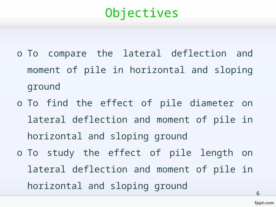
Objectives
o To compare the lateral deflection and moment of pile in
horizontal and sloping ground
o To find the effect of pile diameter on lateral deflection and
moment of pile in horizontal and sloping ground
o To study the effect of pile length on lateral deflection and
moment of pile in horizontal and sloping ground
6

Scope of the Study
o A twelve-storyed reinforced concrete building is considered
in seismic zone 4.
o Dynamic analysis of superstructure is designed with the
application of ETABS computer software.
o For the building design, UBC-97 for loading and ACI (318-
99) for design is used.
o Soil parameters for substructure system are taken from soil
report.
7
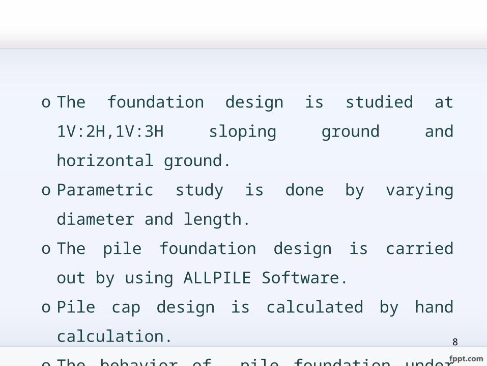
o The foundation design is studied at 1V:2H,1V:3H sloping
ground and horizontal ground.
o Parametric study is done by varying diameter and length.
o The pile foundation design is carried out by using ALLPILE
Software.
o Pile cap design is calculated by hand calculation.
o The behavior of pile foundation under seismic load are
considered by the help of PLAXIS Software.
8

Profile of the Proposed Building
• Type of Structure :12-storeyed R.C Building
• Location :Seismic Zone (4)
• Type of Occupancy :Hotel
• Shape of Building :Rectangular shape
• Size of Building :Length = 130 ft
:Width = 60 ft
• Height of Building :Typical story height = 10 ft
:Bottom story height = 12 ft
:Total height = 134 ft9
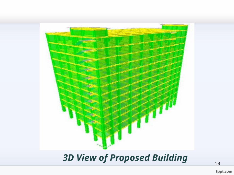
3D View of Proposed Building10
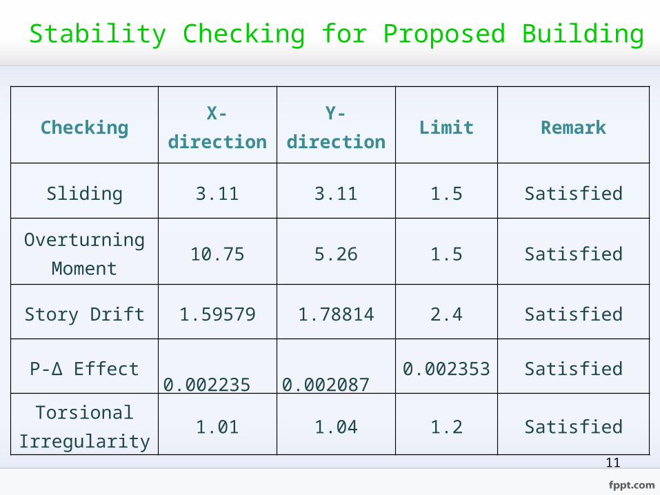
Stability Checking for Proposed Building
Checking X-direction Y-direction Limit Remark
Sliding 3.11 3.11 1.5 Satisfied
Overturning Moment 10.75 5.26 1.5 Satisfied
Story Drift 1.59579 1.78814 2.4 Satisfied
P-∆ Effect 0.002235 0.002087 0.002353 Satisfied
Torsional Irregularity 1.01 1.04 1.2 Satisfied
11
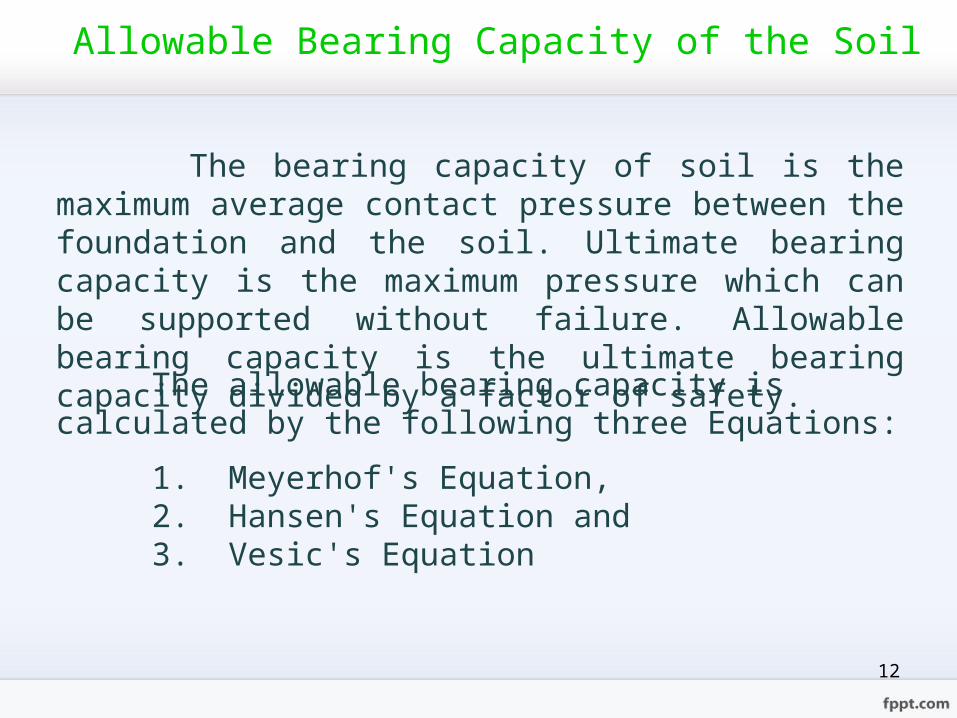
Allowable Bearing Capacity of the Soil
The bearing capacity of soil is the maximum average contact pressure between the foundation and the soil. Ultimate bearing capacity is the maximum pressure which can be supported without failure. Allowable bearing capacity is the ultimate bearing capacity divided by a factor of safety.
The allowable bearing capacity is calculated by the following three Equations:
1. Meyerhof's Equation,2. Hansen's Equation and3. Vesic's Equation
12
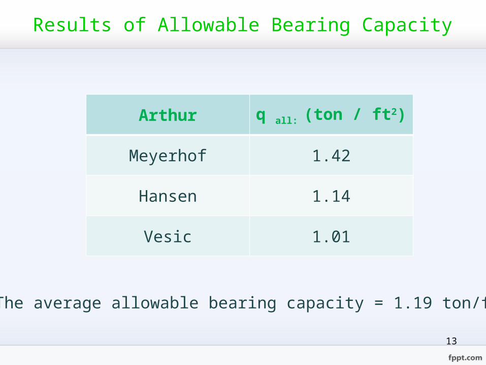
Results of Allowable Bearing Capacity
Arthur q all: (ton / ft2)
Meyerhof 1.42
Hansen 1.14
Vesic 1.01
The average allowable bearing capacity = 1.19 ton/ft2
13
14
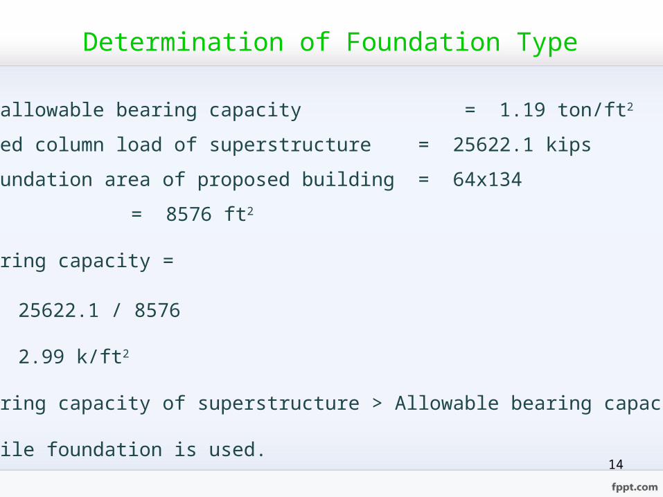
The average allowable bearing capacity = 1.19 ton/ft2
The unfactored column load of superstructure = 25622.1 kips
Available foundation area of proposed building = 64x134
= 8576 ft2
Required bearing capacity =
= 25622.1 / 8576
= 2.99 k/ft2
Required bearing capacity of superstructure > Allowable bearing capacity of soil
Therefore, pile foundation is used.
Determination of Foundation Type
15
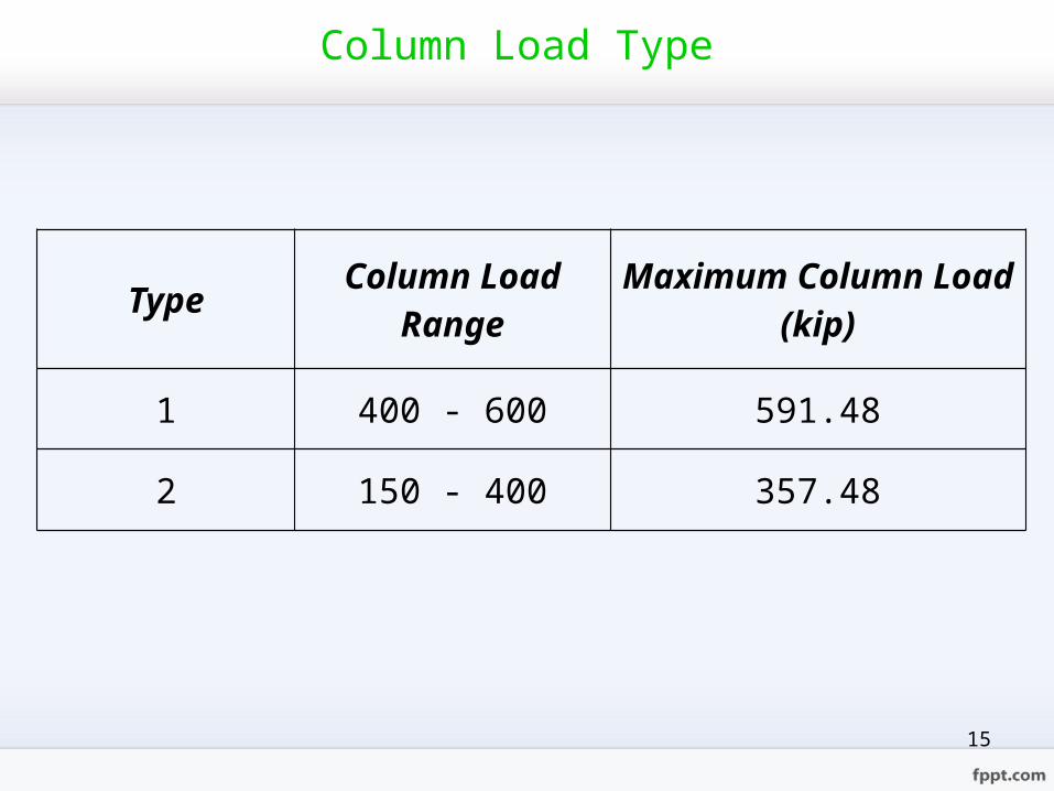
Column Load Type
Type Column Load Range
Maximum Column Load(kip)
1 400 - 600 591.48
2 150 - 400 357.48
16
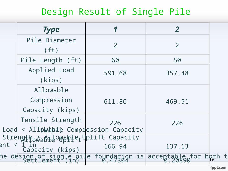
Type 1 2Pile Diameter (ft) 2 2Pile Length (ft) 60 50
Applied Load (kips) 591.68 357.48
Allowable Compression Capacity (kips) 611.86 469.51
Tensile Strength (kips) 226 226Allowable Uplift Capacity (kips) 166.94 137.13
Settlement (in) 0.47304 0.20890
Design Result of Single Pile
Applied Load < Allowable Compression CapacityTensile Strength > Allowable Uplift CapacitySettlement < 1 in
So, the design of single pile foundation is acceptable for both type.
17
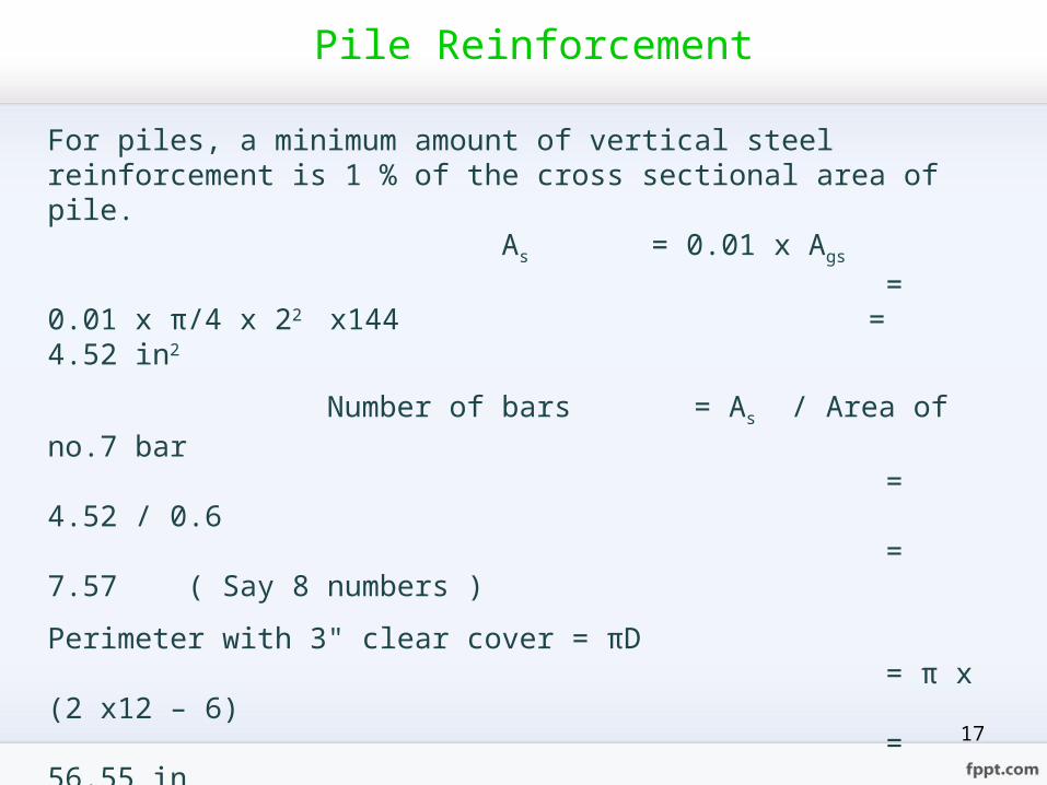
For piles, a minimum amount of vertical steel reinforcement is 1 % of the cross sectional area of pile.
As = 0.01 x Ags
= 0.01 x π/4 x 22 x144 = 4.52 in2
Number of bars = As / Area of no.7 bar = 4.52 / 0.6 = 7.57 ( Say 8 numbers )
Perimeter with 3" clear cover = πD = π x (2 x12 – 6) = 56.55 in
Spacing between bars = Perimeter with 3" clear cover / number of bars = 56.55 / 8 = 6.48 in ( Say 6 in )
Use 8#7 longitudinal bar with 6" spacing in piles.
Pile Reinforcement

18
Detailed of Pile Reinforcement
Type Diameter(ft) Main Steel Reinforcement
Tie Steel Reinforcement Cover(in)
1 2 8#7 #3 spiral @ 3" c/c 3
2 2 8#7 #3 spiral @ 3" c/c 3

19
Results of Pile Cap Design by Hand Calculation
Type Length(ft)
Width(ft)
Thickness(ft)
Flexural design X-direction
Flexural design Y-direction
Temperature and
Shrinkage Steel
1 6 6 2.5 8#8@7"c/c 8#8@7"c/c #5@4"c/c
2 5 5 2 9#6@5"c/c 9#6@5"c/c #5@4"c/c
20
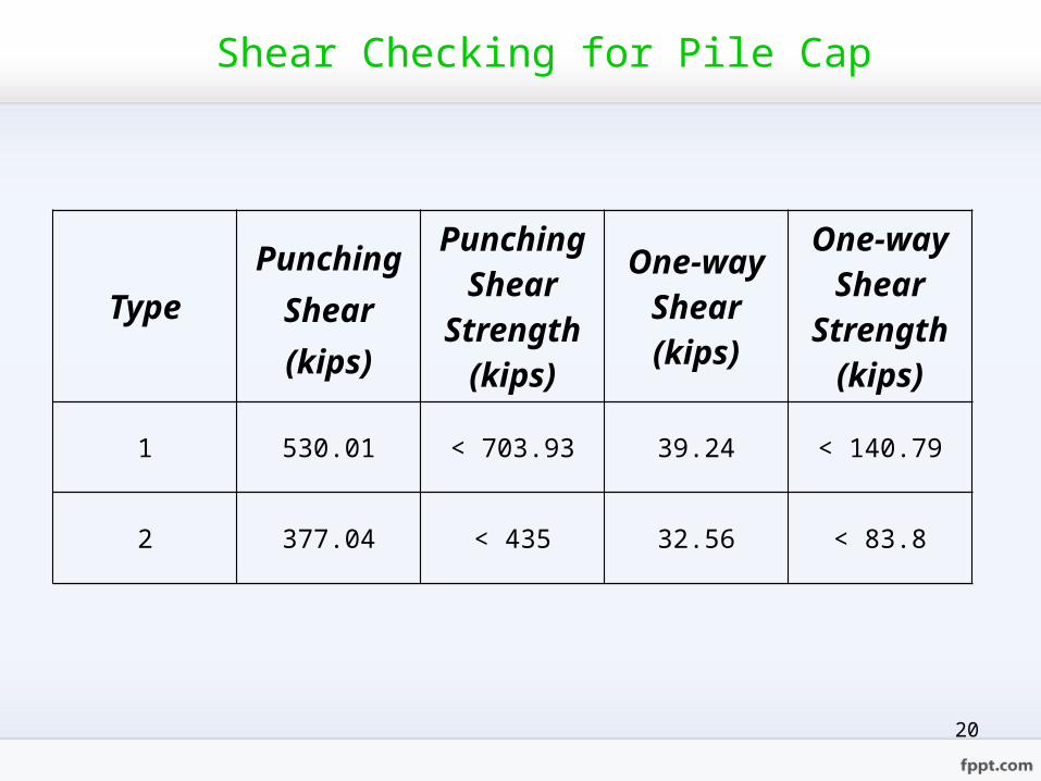
TypePunching
Shear (kips)
Punching Shear
Strength (kips)
One-way Shear (kips)
One-way Shear
Strength (kips)
1 530.01 < 703.93 39.24 < 140.79
2 377.04 < 435 32.56 < 83.8
Shear Checking for Pile Cap
21
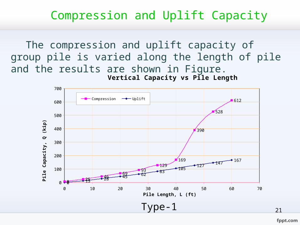
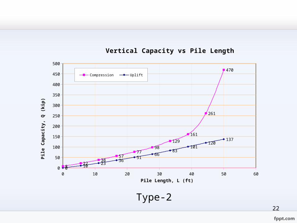
Compression and Uplift Capacity
The compression and uplift capacity of group pile is varied along the length of pile and the results are shown in Figure.
0 10 20 30 40 50 60 700
100
200
300
400
500
600
700
0 13 28 45 6283
105127 147 167
8 2546
6993
129169
390
528
612
Vertical Capacity vs Pile Length
Compression Uplift
Pile Length, L (ft)
Pile
Cap
acity
, Q (k
ip)
Type-1
22
0 10 20 30 40 50 600
50
100
150
200
250
300
350
400
450
500
0 10 2336
5166
83101
120137
822
3857
7798
129
161
261
470
Vertical Capacity vs Pile Length
Compression Uplift
Pile Length, L (ft)
Pile
Cap
acity
, Q (k
ip)
Type-2

23
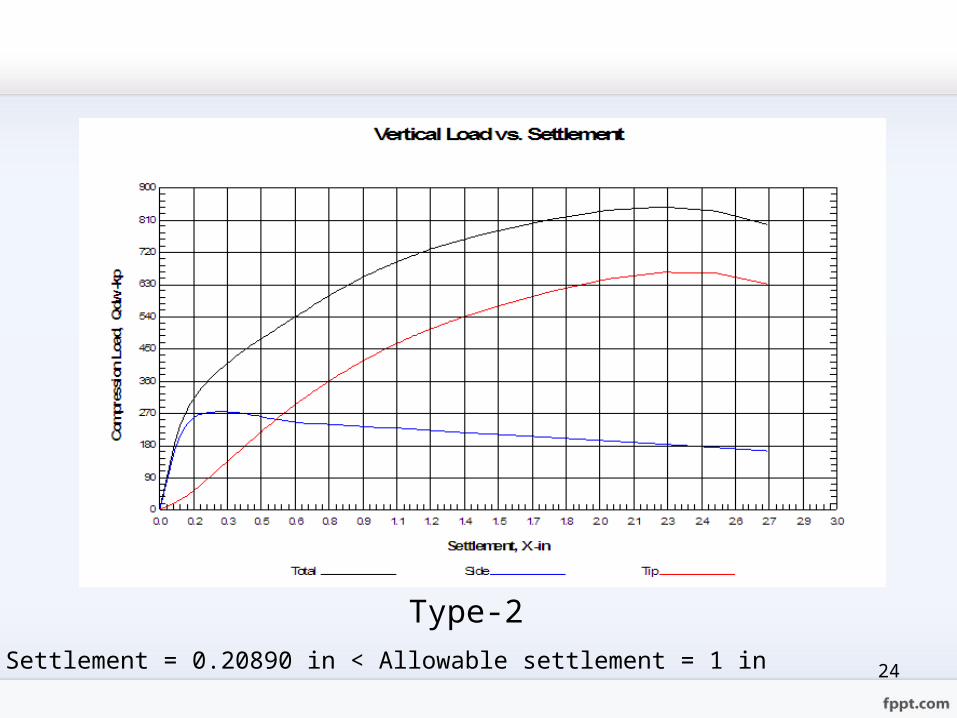
Vertical Load and Settlement
Type-1Settlement = 0.47304 in < Allowable settlement = 1 in
24
Type-2Settlement = 0.20890 in < Allowable settlement = 1 in
25
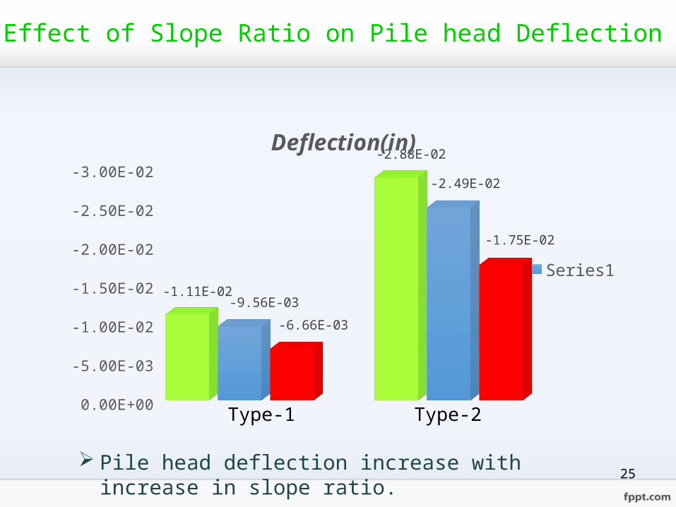
-3.00E-02-2.50E-02-2.00E-02-1.50E-02-1.00E-02-5.00E-030.00E+00
-1.11E-02 -9.56E-03-6.66E-03
-2.88E-02-2.49E-02
-1.75E-02
Deflection(in)
Series1
Type-1 Type-2
Effect of Slope Ratio on Pile head Deflection
Pile head deflection increase with increase in slope ratio.

26
0.00E+005.00E+041.00E+051.50E+052.00E+052.50E+053.00E+053.50E+054.00E+05
1.84E+051.74E+051.53E+05
3.62E+053.44E+053.04E+05Moment(lb-In)
Series1
Type-2
Effect of Slope Ratio on Top Moment
Pile top moment also increase with increase in slope ratio.
Type-1
27
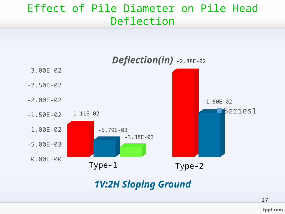
-3.00E-02-2.50E-02-2.00E-02-1.50E-02-1.00E-02-5.00E-030.00E+00
-1.11E-02-5.79E-03-3.38E-03
-2.88E-02
-1.50E-02
Deflection(in)
Series1
Type-1 Type-2
1V:2H Sloping Ground
Effect of Pile Diameter on Pile Head Deflection

28
1V:3H Sloping Ground
-2.50E-02-2.00E-02-1.50E-02-1.00E-02-5.00E-030.00E+00
-9.56E-03-5.00E-03 -2.93E-03
-2.49E-02
-1.30E-02
Deflection(in)
Series1
Type-1 Type-2
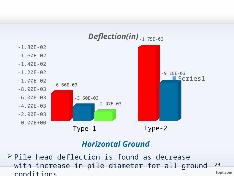
29
Horizontal Ground Pile head deflection is found as decrease with increase in pile
diameter for all ground conditions.
-1.80E-02-1.60E-02-1.40E-02-1.20E-02-1.00E-02-8.00E-03-6.00E-03-4.00E-03-2.00E-030.00E+00
-6.66E-03-3.50E-03-2.07E-03
-1.75E-02
-9.18E-03
Deflection(in)
Series1
Type-1 Type-2

30
Effect of Pile Diameter on Pile Top Moment
1V:2H Sloping Ground
0.00E+005.00E+041.00E+051.50E+052.00E+052.50E+053.00E+053.50E+054.00E+05
1.84E+051.99E+052.13E+05
3.62E+053.93E+05Moment(lb-in)
Series1
Type-1 Type-2

31
1V:3H Sloping Ground
0.00E+005.00E+041.00E+051.50E+052.00E+052.50E+053.00E+053.50E+054.00E+05
1.74E+051.89E+05 2.02E+05
3.44E+05 3.73E+05Moment(lb-in)
Series1
Type-1 Type-2
32
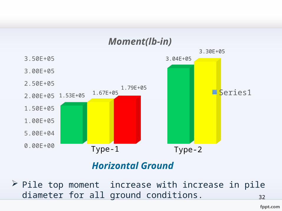
Horizontal Ground
Pile top moment increase with increase in pile diameter for all ground conditions.
0.00E+005.00E+041.00E+051.50E+052.00E+052.50E+053.00E+053.50E+05
1.53E+05 1.67E+051.79E+053.04E+05 3.30E+05Moment(lb-in)
Series1
Type-1 Type-2

33
Effect of Pile Length on Pile Head Deflection
1V:2H Sloping Ground
-1.60E-02-1.40E-02-1.20E-02-1.00E-02-8.00E-03-6.00E-03-4.00E-03-2.00E-030.00E+00
-5.78E-03-5.79E-03-5.80E-03
-1.50E-02 -1.50E-02-1.51E-02Deflection(in)
Series1
Type-1 Type-2
34
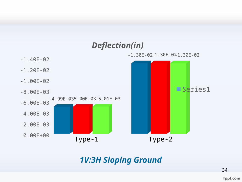
1V:3H Sloping Ground
-1.40E-02-1.20E-02-1.00E-02-8.00E-03-6.00E-03-4.00E-03-2.00E-030.00E+00
-4.99E-03 -5.00E-03 -5.01E-03
-1.30E-02 -1.30E-02 -1.30E-02
Deflection(in)
Series1
Type-1 Type-2
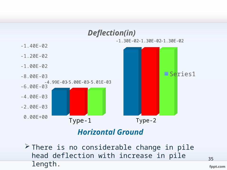
35
Horizontal Ground
There is no considerable change in pile head deflection with increase in pile length.
-1.40E-02-1.20E-02-1.00E-02-8.00E-03-6.00E-03-4.00E-03-2.00E-030.00E+00
-4.99E-03-5.00E-03 -5.01E-03
-1.30E-02 -1.30E-02 -1.30E-02Deflection(in)
Series1
Type-1 Type-2
36
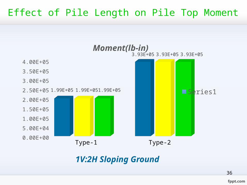
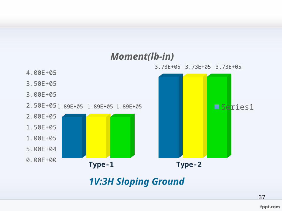
Effect of Pile Length on Pile Top Moment
1V:2H Sloping Ground
0.00E+005.00E+041.00E+051.50E+052.00E+052.50E+053.00E+053.50E+054.00E+051.99E+051.99E+051.99E+05
3.93E+053.93E+053.93E+05Moment(lb-in)
Series1
Type-1 Type-2
37
1V:3H Sloping Ground
Type-1 Type-20.00E+005.00E+041.00E+051.50E+052.00E+052.50E+053.00E+053.50E+054.00E+05
1.89E+05 1.89E+05 1.89E+05
3.73E+05 3.73E+05 3.73E+05Moment(lb-in)
Series1
38
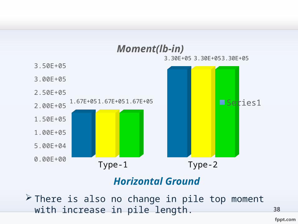
Horizontal Ground There is also no change in pile top moment with increase in pile
length.
0.00E+005.00E+041.00E+051.50E+052.00E+052.50E+053.00E+053.50E+05
1.67E+05 1.67E+05 1.67E+05
3.30E+05 3.30E+05 3.30E+05
Moment(lb-in)
Series1
Type-1 Type-2

39
Conclusion
1. Lateral deflection and moment increase with increase in slope ratio. When 1V:2H slope decrease to 1V:3H slope, pile head deflection decrease to 14% and top moment decrease to 5%. When 1V:2H slope decrease to horizontal ground, pile head deflection decrease to 40% and top moment decrease to 16.5%.
2. The effect of pile diameter is studied and it is concluded that lateral deflection decrease with increase in diameter of pile for same length. This is due to the increase in surface area, pile stiffness and moment of inertia. But, pile lateral moment increase because moment is directly proportional with pile stiffness by Subgrade Reaction Approach.
3. The increase in length of pile is not significant affects on lateral deflection and moment of pile. The increase of pile length only affects the vertical capacity of pile depending upon the underlying soil conditions.
40
Future Plan
o Behavior of pile foundation in horizontal and sloping ground
considering seismic effect will be evaluated by the help of
PLAXIS Software.

41
THANK YOU FOR YOUR ATTENTION
![Three Year Plan LBC Presentation 2012.pptx [Read-Only]edr.state.fl.us/Content/presentations/long-range... · 2012-09-12 · (3rd Longest Period in Nation) • National Average –](https://static.documents.pub/doc/80x56/5fa80d0990e8d15c6023ef99/three-year-plan-lbc-presentation-2012pptx-read-onlyedrstatefluscontentpresentationslong-range.jpg)
![[MS-PPTX]: PowerPoint (.pptx) Extensions to the …interoperability.blob.core.windows.net/files/MS-PPTX/[MS...1 / 78 [MS-PPTX] - v20150904 PowerPoint (.pptx) Extensions to the Office](https://static.documents.pub/doc/80x56/5ad11a0c7f8b9aff738b549d/ms-pptx-powerpoint-pptx-extensions-to-the-ms1-78-ms-pptx-v20150904.jpg)
![[MS-PPTX]: PowerPoint (.pptx) Extensions to the Office ...interoperability.blob.core.windows.net/files/MS-PPTX/[MS-PPTX... · 1 / 76 [MS-PPTX] — v20140428 PowerPoint (.pptx) Extensions](https://static.documents.pub/doc/80x56/5ae7f6357f8b9a6d4f8ed3b3/ms-pptx-powerpoint-pptx-extensions-to-the-office-ms-pptx1-76-ms-pptx.jpg)

![ID 1 SESSION 4.pptx [Autoguardado].pptx](https://static.documents.pub/doc/80x56/55cf8c675503462b138c00e6/id-1-session-4pptx-autoguardadopptx.jpg)


![[MS-PPTX]: PowerPoint (.pptx) Extensions to the Office ...MS-PPTX... · [MS-PPTX] - v20181211 PowerPoint (.pptx) Extensions to the Office Open XML File Format Copyright © 2018 Microsoft](https://static.documents.pub/doc/80x56/5edb5856ad6a402d666584d0/ms-pptx-powerpoint-pptx-extensions-to-the-office-ms-pptx-ms-pptx.jpg)
![[MS-PPTX]: PowerPoint (.pptx) Extensions to the Office ...MS-PPTX].pdf · [MS-PPTX]: PowerPoint (.pptx) Extensions to the Office Open XML File Format ... PowerPoint (.pptx) Extensions](https://static.documents.pub/doc/80x56/5ae7f6357f8b9a6d4f8ed3a1/ms-pptx-powerpoint-pptx-extensions-to-the-office-ms-pptxpdfms-pptx.jpg)
