on Off-Highway Trucks 3-1Tooling for Variable Speed Fan Clutch on Trucks 3-10Water Pump Packing Wrench 4A-0334 3-1
Water Pump Seal Installation Tools 3-17Water Pump Seal Installer 135-7629 3-1Water Pump Seal Installer 9U-6956 3-2Water Pump Seal Installers 3-1Water Pump Tool Group 5P-7361 3-13
Crankshaft, Main Bearings and Flywheel 3-213500 Engine Main Bearing Cap Removal/
Installation Tool 3-36Adapter FT0915 3-22Alignment Group 9U-6200 3-32Alignment Tool 4C-5501 3-3Bearing Cap Tools 3-36Bearing Removal and Installation Tools 3-37Bolt FT1896 3-25Bolt FT1907 3-38Bracket Assembly FT1341 3-25
BrakeSaver Rotor Support 5P-8718 3-24Cat C6.6 Engine / Perkins Vista D Engine Tools 3-34Chip Deflector FT1120 3-23Cold Solvent Tank FT1587 3-24Crank Gear Puller 137-7293 3-22Crankshaft Distortion Gauge 155-8795 3-30Crankshaft Gear Installation Tools 3-2Crankshaft Main Bearing Removal Tool Group FT1794 3-37Crankshaft Oil Seal Installers 3-32Crankshaft Seal and Wear Sleeve Installation Tools
(Silicone and Hydrodynamic) 3-26Crankshaft Seal Installer FT2794 3-3Crankshaft Support Group 5P-8637 3-24Dimensions to Modify 1P-2321 Puller Assembly FT0884 3-39Distorter Adapter 1U-7325 3-30Distorter Adapter 6V-3143 3-3Distorter Ring 4C-4869 3-30
Distorter 5P-7409 3-30Drill Fixture Fixture FT1104 3-23Driver Body FT0101 3-39Driver Body FT0102 3-39Driver Body FT0106 3-39Driver Body FT0107 3-40Driver Body FT0807 3-40Driver Body FT0885 3-40Driver Handle FT0108 3-39Driver FT0143 3-42Drivers 3-42Flywheel Guide Pin 9U-7994 3-25Flywheel Lifter 8F-4423 3-25Front Seal Installer Group 9U-6180 3-33Front Seal Installer 1U-7430 3-33
Wear Sleeve and Seal Installer 5P-3022 3-25Wear Sleeve Distorter Group 5P-7318 3-29Wear Sleeve Installers 3-29Wear Sleeves and Drivers 3-41
Cylinder Block and Liners 3-43Adapter Plates for 7F-1857 Puller 3-56Alignment Gauge FT2736 3-60Bearing Driver 6V-7912 3-62Block Pressure Test Group FT1855 3-43Bottoming Tap 4C-9645 3-61Bridge Group 1U-9897 3-60Chamfering Group 1P-3565 3-45Compression Test Kit 9U-6274 3-44Counterbore Tool Group 159-9404 3-52Counterbore Tool Group 9U-7990 3-50Counterboring Tool Group 8S-3140 3-49
Valve Seat Puller Group 130-1449 3-80Valve Seat Puller Group 8S-7170 3-80Valve Spring Assembly 276-1221 3-77Valve Spring Compressor Group for 3176 Engine 3-76Valve Spring Compressor Group for 3406E Engine 3-76Valve Spring Compressor Group for C13 Engine 3-76Valve Spring Compressor Group 1U-9347 3-73Valve Spring Compressor Group 7F-4292 3-72Valve Spring Compressor Group 9U-6195 3-77Valve Spring Compressor Group FT1886 3-75Valve Spring Compressor 1P-3527 3-7Valve Spring Compressor FT1566 3-75Valve Spring Tester 8S-2263 3-78Valve Stem Gauge 6V-0087 3-83
Electrical and Ignition Tools 3-105Adapter Cable 1U-9710 3-108
Alternator Pulley Tool Group 1P-2977 3-108Battery Cable Repair Kit 6V-3025 3-106Bearing Driver FT1031 3-105Bearing Insert FT0753 3-108Bearing Insert FT0754 3-108Carrying Case and Accessories for
Discontinued 8T-0900 Clamp-on Ammeter 3-11Clamp On Ammeter 225-8266 3-11Collet 6V-7914 3-105Deutsch Connector Repair Kit 4C-3406 3-107Driver Assembly 192-7039 3-110Exciter Tester Group FT1488 3-11Expansion Rod 6V-7913 3-105Ferrule Crimp Tools 3-106Indicator Bracket FT2449 3-110Installer Group 9U-7226 3-106Magneto Wrench FT2396 3-10
Tool Group (Valve Spring and In jector Sleeve) 283-9697 3-121Tool Kit, 3406E Engine 9U-7530 3-120Tool Kit, C-9 Engine 196-3165 3-120Water Line Adapter FT0940 3-114Water Line Adapter FT1003 3-118
Fuel System Test Tools 3-122Access Cover, AVM FT2620 3-123Adapter Group 2P-5510 3-145Adapter Group 5P-5240 3-147Adapter Group 5P-5241 3-148Adapter Group 5P-9737 3-146Adapter Group 6V-2009 3-134Adapter Group 6V-6046 3-137Adapter Group 6V-6090 3-145Adapter 4C-9309 3-157Adapter 5P-7448 3-153
Air Supply and Test Group 4C-8740 3-148AVM 2-PC Fuel Injection Equipment Test Stand 158-2262 3-123Basic Mounting/Setup Group 136-8330 3-131Block Group 1U-6662 3-151Calibration Fluid and Diesel Fuel Test Kit 9U-7840 3-131Calibration Fluid 3-129Diagnostic Unit 6V-7904 3-128Extension Tube 1U-8857 3-154Extension FT1384 3-154FIETS Nozzle Block and Lines 3-126Filter Block to Metering Unit Tubing FT2643 3-122Forcing Screw Assembly FT1979 3-157Fuel Collector 8S-2270 3-154Fuel Injection Test Bench (480 Volt, 50 Hz) 139-1437 3-122Fuel Injection Test Bench (480 Volt, 60 Hz) 132-9753 3-122Fuel Injection Tube Assemblies 3-128Fuel Pump Adapter Group 6V-9441 3-148Fuel Ratio Control Adjusting and Synchronizing Wrench 159-1783 3-156Governor Adjust Tool Group 1U-9087 3-155Governor Calibration Bench 1U-7326 3-155Governor Disassembly and Assembly Tool Group 1U-9088 3-155Governor Drive Group 4C-6907 3-148Governor Torque Arm 1U-9361 3-150Hartridge AVM 20-12C Fuel Injection Test Benches 3-122Hartridge Fuel Injection Equipment Test Stands 3-126Heavy Duty Drive Group 4C-8192 3-130Hex Ball Driver, 4 mm Standard 4C-8996 3-157Holding Block Group 1U-6663 3-151Holding Block Group 4C-6566 3-151Injection Pump Off-Engine Disassembly, Assembly,
and Bench Test 3-143
Injector Sleeve 6V-4172 3-152Line Assembly FT1743 3-154Master Nozzle Group 9U-6705 3-128Mounting and Drive Group 4C-8200 3-138Mounting Drive Group 135-2916 3-135NEHS0594 Using TMI for Finding Injection Pump
Off Engine Test Specifications 3-129Nozzle Block to Filter Block Tubing FT2642 3-122Nozzle Tester Group 5P-4150 3-153Plate 4C-9279 3-152Power Supply Adapter 9U-6143 3-151Pressure Gauges 3-130Pump Adapter 5P-5237 3-145Repair Kit 1U-9578 3-153Sleeve Metering Adapter Group 6V-3116 3-133Storage Bags 3-129Test and Adjust Group 4C-8980 3-148Test Stand, 208/240 V 6V-7900 3-126Test Stand, 380/420 V 1U-8213 3-126Test Stand, 440/480 V 1U-8212 3-126Tester 1U-6661 3-151Tool Group, 3161 Governor Torque Control 4C-6100 3-150Tube Assemblies 3-154
Valve Group 1P-1795 3-129Wrench 148-3605 3-156Zexel and Nippondenso Fuel Pump
and Governor Disassemble and Assemble Tools 3-140Zexel and Nippondenso Fuel Pump
and Governor Test and Adjust Tools 3-141
Fuel System Repair and Adjust 3-157Adapter Assembly FT0960 3-181Adapter Group 6V-9145 3-160Adapter 208-9388 3-162Air Regulator Assembly 5P-2413 3-199Air Test Kit FT1906 3-199Alignment Pin FT1525 3-189Applicator 4C-4354 3-202Assembly Fixture FT1820 3-200Backup Ring Installer 149-2956 3-191
Pistons, Rings and Connecting Rods 3-207Bushing Adapter 4C-9750 3-217Compressor Group 1U-7616 3-209Compressor 1U-6684 3-210Connecting Rod Boring Machine 5P-3550 3-211Connecting Rod Checking Fixture 5P-2050 3-213
Expander Segments Group 9U-5949 3-212Expander 1U-6683 3-210Expanding Segment Group (1.1) 9U-5948 3-212Fabricated Tools for Use in Reconditioning Piston
and Connecting Rod Assemblies 3-219Feed Cylinder 5P-4778 3-212Gauge Group 1U-6431 3-208Gauge FT1022 3-209Induction Bearing Heaters and Ring Heater 3-220Parts Baskets for Handling Pistons and Piston Pins 3-218Pin Bushing Adapter 1U-6242 3-216Pin Bushing Adapter 1U-9032 3-216Pin Bushing Adapter 4C-8725 3-217Pin Mandrel, Bushing In 9U-5918 3-214Pin Mandrel, Bushing Out 9U-5917 3-214Piston Pin Installer FT2984 3-211Piston Pin Installer FT2985 3-211
Piston Ring Compressors 3-210Piston Ring Expanders 3-209Piston Ring Groove Gauge Groups 3-208Piston Ring Groove Gauge 5P-3519 3-207Piston Ring Groove Gauge 9U-5931 3-208Piston Storage Cabinet and Connecting Rod Assembly FT1571 3-218Polishing Wheel 8T-7748 3-218Push Adapter 1U-6243 3-216Push Adapter 1U-9034 3-216Push Adapter 4C-8727 3-217Pushing Adapter 4C-9749 3-217Reconditioning Connecting Rod Tools 3-217Ring Compressor Group 255-8897 3-209Ring Expander 4C-3601 3-210Rod Locating Group 9U-5945 3-212Slide Hammer Adapter FT1888 3-216Snap Ring Pliers 139-9039 3-217
Spacer 1U-6244 3-216Spacer 1U-9033 3-216Spacer 4C-8726 3-217Spacer 4C-9751 3-217Tools for Connecting Rod Pin Bearing Removal
and Installation 3-214Tools for Removing and Installing Tapered
Connecting Rod Bearings 3-215
Camshaft and Timing Gear Tools 3-221Adapter Group 1P-5545 3-224Adapter 6V-4869 3-224Adjustable Idler Assembly 9U-7255 3-230Air Compressor Gear Holder 132-5451 3-229Alignment Tool FT2781 3-231Cam Tool Group 177-8003 3-223Camshaft Alignment Pilot Assembly 131-1525 3-221Camshaft Alignment Sleeve FT0751 3-221Camshaft Bearing Installation and Removal Group 8S-2241 3-224Camshaft Bearing Removal and Installation Tools 3-226Camshaft Bearing Remove/Install Tools 3-225Camshaft Bearing Tool Group 6V-4077 3-225Camshaft Guide Assembly 125-0201 3-222Camshaft Installation Tools 3-221Camshaft Pilot 125-0200 3-222Camshaft Plates, Pilots, and Sleeves 3-226Camshaft Removal and Installation Tools 3-223Camshaft Retainer 132-3904 3-226Gear Installation Group 8F-3671 3-227Gear Installation Tools 3-227Gear Removal Plate 8F-3672 3-227
Guide Bolt 9U-6896 3-228Idler Shaft Removal Group 9U-6148 3-230Idler Shaft Retrofit Tool Group 4C-9991 3-229Indicator Bracket 9U-7324 3-231Plug 6V-6174 3-224Puller Group 167-3834 3-228
Puller Group 173-2021 3-227Puller Group 4C-5613 3-229Puller Group 8S-2264 3-228Puller Plate 5P-1666 3-224Shaft Installer Group 195-7503 3-230Sleeve 8S-8375 3-228Socket Assembly 193-9199 3-227Spacer Tube 5P-1667 3-224
Guide Group (Part of 9U-5105 Group) 4C-6357 3-258Guide, Piston Pin (Part of 9U-5105 Group) 1U-8692 3-258Handle Rod (Part of 9U-5105 Group) 126-6920 3-255Handling Tool Group (Part of 9U-5105 Group) 8T-0960 3-254Head Lifting Bracket (3600 In-line) 126-6919 3-255Head Lifting Bracket (3600 Vee) 126-6918 3-255
Idler Gear Wrench (Part of 9U-5105 Group) 4C-9451 3-253Idler Gear Wrench (Part of 9U-5105 Group) 4C-9452 3-253Internal Pliers Assembly (Part of 9U-5105 Group) 136-1452 3-258Liner Puller Group (Part of 9U-5106 Group) 6V-7073 3-261Lines Group (Part of 9U-5105 Group) 8T-3035 3-255Main Bearing Driver (Part of 9U-5105 Group) 134-0932 3-257Oil Drain Tool Group (Part of 9U-5105 Group) 1U-9824 3-253Phoenix Screwdriver (Part of 9U-5105 Group) 9U-6461 3-254Piston Support Group, (Part of 9U-5105) 145-5190 3-257Pressure Gauge (Part of 9U-5105 Group) 8T-0820 3-255Puller Group (Part of 9U-5105 Group) 8T-0890 3-254Rod Guide Group (Part of 9U-5105 Group) 8T-3022 3-258Shank-Hex (Part of 9U-5105 Group) 4C-9818 3-259Snap Ring Retainer (Part of 9U-5105 Group) 9U-5981 3-259Timing and Fuel Setting Tool Group
(Part of 9U-5106 Group) 4C-6594 3-262Universal Joint (Part of 9U-5105 Group) 4C-9819 3-259
Water Pump Seal Driver (Part of 9U-5105 Group) 8T-3034 3-252Bridge Dowel Gauge 130-2534 3-248Camshaft Separation Assembly 156-7159 3-266Check Valve (Dummy) 143-8997 3-264Cleaning Kit 145-0316 3-267Cylinder Head Stud Socket Assembly 184-3131 3-247Cylinder Liner Spacer Assembly 191-1135 3-263Cylinder Pressure Measuring Indicator Group, 3000 PSI 4C-6585 3-247Cylinder Tool Group 9U-6249 3-269Diesel Valve Seat Group 147-2285 3-265Distorter Block 121-7700 3-246Dowel Puller Group 1U-9570 3-249Exhaust Manifold Wrenches 3-269G3600 Operator Tool Group 146-2727 3-263Governor Calibration Tool 4C-6583 3-265Head Repair Tool Group 9U-7522 3-268Hydraulic Pumps 3-272
Injector Seat Cleaning Brush 130-6993 3-248Leak Down Check Tool 143-8995 3-264Main Bearing Journal Cover Assembly 9U-5102 3-265Maintenance Tool Group 146-2726 3-264Overhaul Protection Kit 229-3639 3-250Piston Support 156-7160 3-266Prechamber Machining Tool Group (G3600) 187-6273 3-267Pump Accessory Group 229-9453 3-272Pump Tool Group 9U-6250 3-269Ratchet, 3 ⁄ 8 inch Drive 194-4944 3-269Ring Groove Gauges 3-250Rod Cap Guide (3618) 178-5063 3-267Safety Retainer Group 4C-9839 3-247Seal Installer Group 148-9704 3-269Seal Installer 1U-6241 3-246Socket 4C-6987 3-247Spark Ignited Tool Group 9U-5107 3-251
Cleaning Tool Group (part of 9U-5107 Group) 9U-5156 3-252Liner Puller Group (part of 9U-5107 Group) 4C-8568 3-251Piston Ring Compressor Group
(part of 9U-5107 Group) 4C-9043 3-251Ring Expander Group (part of 9U-5107 Group) 4C-8995 3-251
Stud Assembly 121-7705 3-246Stud Tensioner Tool Group 179-1904 3-271Stud Tensioner Tool Group 191-5320 3-272Stud Tensioner Tool Group 207-5034 3-265Support Tray Rail 160-4901 3-274Support Tray 160-0475 3-274Template Seal 151-8689 3-267Thread Repair Insert 128-5113 3-250Threaded Insert 133-1531 3-250Tool Group (NA297) 187-3703 3-270
• Used to disassemble turbocharger rotating assemblies by positioningturbine wheel in 9S-6343 Fixture Assembly for removal of shaft nut
• Contains sockets required to hold Schwitzer turbine wheels
• Set of 4 turbine holders available to hold AiResearch turbine wheels
• Frame of fixture retains holder in place
ID: B22568T1
Item Part No. Description
1 9S-6343 Fixture Assembly
Turbine Holders (one shown):
2 8S-9943 T-68S-9944 T-128S-9946 T-18
ID: C09503T1
FT0175 Ring Expander Sleeve
• Used to service turbocharger (see chart)
ID: D00496T1
ID: D00502T1
FT0165 Modified Fixture
• Existing FT0165 Fixture can be modified according to boxed dimensionsso that only one adapter is needed for disassembly and assembly of allturbochargers.
• Material: SAE1020 steel
ID: D00520T1
FT0168 Fixture Adapter
• Used to service turbocharger (see chart)
• Material: SAE1020 steel
Dealer Service Tools 2006
Engine Tools
Induction
ling System
nkshaft, Mainrings and Flywheel
nder BlockLiners
nder Head, ValvesCam Followers
ctricalIgnition Tools
e System
ine Test Tools
System Test Tools
System RepairAdjust
ons, Rings andnecting Rods
mshaft and Timingr Tools
rting Systems
ine LiftingPositioning
0 Engine Tools
3-2
9S-6363 Turbocharger Fixture Group
• Used for disassembly and assembly of current and non-currentturbochargers
• Mounting plate tilts 90° so turbochargers can be positioned verticallyor horizontally.
• In either position, mounting plate can be rotated to 8 fixed positions in 360°.
261-0940 Bendix Air Compressor Test KitSMCS Code: 1803-035, 0701Model: All Caterpillar Truck Engines with Bendix Air CompressorEssential ToolWarranty: None - Considered a Consumable
NEW TOOL
• Allows technician to accurately troubleshoot online air systemon engine with Bendix Air Compressor
• Required to remove impeller from water pump shaft on 3406B Engines (8S-2264 Puller Group,used to pull water pump impellers on 3406 Engines, cannot be used for this task on 3406B.)
• Designed to fit narrower bolt hole spacing on 3406B impellers
• Used to hold ABB TPS57 turbocharger cartridge for disassembly and assembly
• Used with 180-5286 Socket for maintenance of turbine bearing
• Permits one-man operation while applying sockets to each end of turbine shaft
ID: C79859T1
102-9720 Air Filter Cleaning KitSMCS Code: 1054-070, 0680Model: 3406, 3408, and 3412, Heavy-Duty Marine EnginesWarranty: Six Months
• Used to clean air filter elements
• Kit includes cleaner, spray nozzle, and air filter oil
• Cleaner is specially formulated for removing dirt from cotton gauze elements — prevents shrinkageor other damage to filter element when used according to manufacturer’s directions
• Air filter oil greatly increases effectiveness of filter — oil is added to filter after cleaning
ReferenceSEHS9541 Special Instruction
ID: C66640T1
Air filter oil 0.227 L (8 oz)
Ai r fil ter cleaner 0.946 L ( 32 oz)
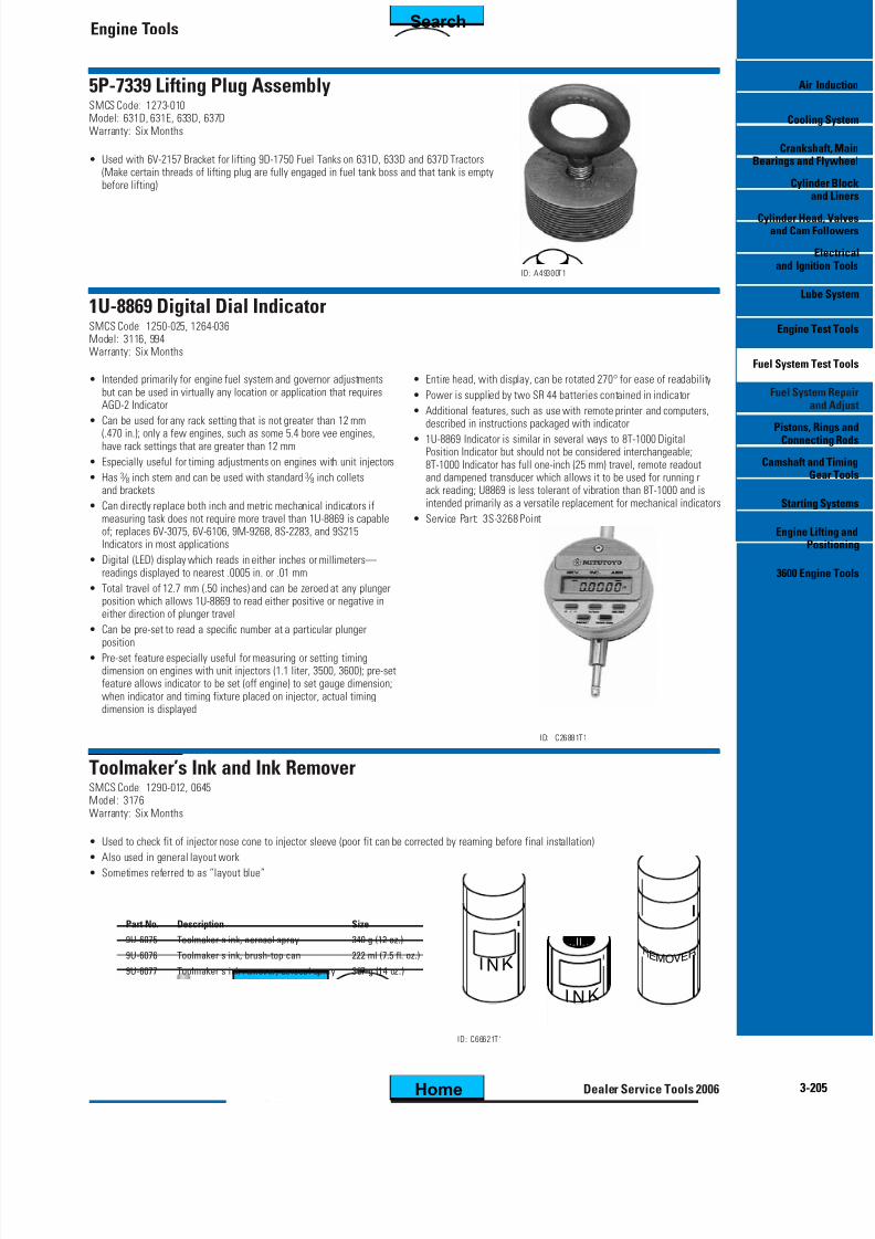
Differential Pressure Regulator Testing and Reconditioning ApparatusSMCS Code: 1051-036Model: Multiple Engine ModelsWarranty: Six Months
• Required to test and calibrate differential pressure regulators
• Basic test apparatus required for fuel operated pressure ratio controls and exhaust bypass valves
• Additional parts required for pneumatic pressure ratio control
ReferenceFE035027 and FE034610 Special Instructions
• Used to check reconditioned cartridge assemblies in turbocharger for correct end play movement
• Increases service life by early detection of end play movement not within correct tolerances(End clearance problems can result in turbocharger failure, which could result in engine failure.)
ID: B80397T1
FT1782 Turbocharger Test StandSMCS Code: 1052-036Model: Multiple Engine ModelsWarranty: None
• Used to test all current turbochargers that are used on Caterpillar engines
• Used to test seal ring leakage, end housing clearance and shaft rotation
• Can also give break-in before installation—uses air and oil pressure to provideconditions that are similar to normal operation
• Has oil heater to raise temperature of oil to normal engine oil temperature
Item Part No. Description
1 5P-6517 Dial Indicator
2 5P-6516 Angle Plate
Engine Tools
Air I
Coolin
CrankshBearings and F
Cylindan
Cylinder Heaand Cam F
Eand Igniti
Lub
Engine T
Fuel System Te
Fuel Systean
Pistons, RConnect
Camshaft anGe
Starting
Engine LiPo
3600 Engi
3-7Dealer Service Tools 2006
ID: A39325-1T1
5P-6518 Parts Reusability Fixture GroupSMCS Code: 1052-015, 1052-017Model: Multiple Engine ModelsWarranty: Six Months
• Used to measure turbocharger shaft straightness and engine valve lip thickness
• Parts securely positioned on V-blocks while measurements are taken with metric dial indicator
5P-7381 Lifting BracketSMCS Code: 1353-017Model: Multiple Engine ModelsWarranty: Six Months
• Bolts to pressure relief valve boss for removal of radiator units on 776 and 777 Trucks• Has 2 sets of holes in bracket for positioning over center of gravity for either group
• Used to remove AMOCs radiator cores on 950 through 994 Wheel Loaders, all Wheel Tractors,and any vehicle using AMOC Radiator Cores
• Allows one-person removal and installation of radiator cores
• To install: place bale in “down position” and attach bracket over top of radiator core withcenter hole over core protrusion to restrict side movement
• To lift: push bracket down to properly position spring-loaded wings and raise bale to“up position”; tighten set screws to positive lock
• To remove: place radiator core on ground (remove weight) and place bale in “down position”
Lift capacity 45.4 kg (100 lbs)
208-1350 Radiator Fin CombSMCS Code: 1353-023
Model: Multiple Engine ModelsWarranty: Six Months
• Multi-head tool which handles 8, 9, 10, 12, 14, and 15 fins/inch
• Breaks down easily for tool box storage
ID: C27195T1
FT2978 NozzleSMCS Code: 1353-023
Model: Most ModelsWarranty: None
• Used to clean hard to reach places between radiator coreand other cooling components
• Used with 156-0931 Air Gun
212-8144 SocketSMCS Code: 1372-012Model: 3304, 3306Warranty: Six Months
• Used to loosen and tighten radiator drain valve on 3304 and 3306 Engines
• Used to change fan blade pitch on machines equipped with reversible fan bladesID: C09510T1
ID: D00772T1
FT2461
FT2462
FT2467
FT2464
FT2465
FT2463
FT2466
21
4
35
6
7
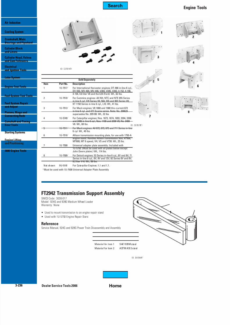
Item Part No. Description Material
1 FT2461 Pressing Bar SAE 4140 steel
2 FT2462 Pressing Tube SAE 4140 steel
3 FT2463 Ring SAE 4140 steel
4 FT2464 Plate SAE 4140 steel
5 FT2465 Plate SAE 4140 steel
6 FT2466 Mounting Plate SAE 1020 steel
7 FT2467 Rotating Plate
Dealer Service Tools 2006
Engine Tools
Induction
ling System
nkshaft, Mainrings and Flywheel
nder BlockLiners
nder Head, ValvesCam Followers
ctricalIgnition Tools
e System
ine Test Tools
System Test Tools
System RepairAdjust
ons, Rings andnecting Rods
mshaft and Timingr Tools
rting Systems
ine LiftingPositioning
0 Engine Tools
3-10
Tooling for Variable Speed Fan Clutch on TrucksSMCS Code: 1359-017Model: Multiple Engine ModelsWarranty: None
• Provides tooling needed to disassemble and assemble variable speed fan clutch on 768C, 769C, 771C,772B, 773B, 775B, 784B, 785B, 789B, and 793B Trucks
• FT2461 and FT2467 used to disassemble and assemble 6I-4427 and 123-6968 Fan Clutches
• FT2464 and FT2465 Plates used to disassemble and assemble 100-8105 and129-9494 Fan Clutches which are both replaced by 133-5969 Fan Clutch
Disassembly and Assembly Tooling for 200 Rockford Fan ClutchSMCS Code: 1359-017Model: Multiple Engine ModelsWarranty: None
• Used to disassemble and assemble 183-5116(200 Series Rockford) Variable Speed Fan Clutchon D9R (s/n ABK and ACL) and D10R(s/n 3KR and AKT) Track-Type Tractors
• Heat treat FT2814 through FT2820 to RC 38 to 42
ReferencesSENR8603-01 Variable Speed Fan Clutch
Item Part No. Description Material
1 FT2814 Bearing Remover SAE 4140 steel
2 FT2815 Bearing Installer SAE 4140 steel
3 FT2816 Bearing Installer SAE 4140 steel
4 FT2817 Bearing Remover SAE 4140 steel
5 FT2818 Installation Ring Plate SAE 4140 steel
6 FT2819 Fan Hub and Shaft Assembly Removal Plate SAE 4140 steel
7 FT2820 Bearing and Seal Removal and Installation Plate SAE 4140 steel
8 FT2821 Clutch Body Hold Fixture Assembly SAE 1020 steel
9 FT2822 Fan Mounting Hub Removal and SAE 1020 steelInstallation Fixture Assembly
Tooling for Variable Speed Fan Clutch on Off-Highway TrucksSMCS Code: 1359-017Model: Multiple Engine ModelsWarranty: None
• Used to disassemble and assemble variable speed fan clutch on 784C, 785C, 785CHAA, 789C, and 793C Off-Highway Trucks
• Ensures proper positioning and installation of clutch parts
• Material (all parts): SAE4140 steel
ReferenceRENR2634 Service Manual, Variable Speed Fan Clutch
• Used to pressurize cooling systems to detect leaks
• Can also test dash gauges, relief valves, and pressure caps
• All items in figure are included
ID: A69886-1T1
Dealer Service Tools 2006
Engine Tools
Induction
ling System
nkshaft, Mainrings and Flywheel
nder BlockLiners
nder Head, ValvesCam Followers
ctricalIgnition Tools
e System
ine Test Tools
System Test Tools
System RepairAdjust
ons, Rings andnecting Rods
mshaft and Timingr Tools
rting Systems
ine LiftingPositioning
0 Engine Tools
3-12
I tem Part No. Description
1 6V-7775 Gauge 0- 205 kPa (0-30 PSI)
2 2P-2331 Release Valve (Not included in earlier pump groups; to permit testing ofautomotive-type cooling systems, ordered and install on earlier pumps)
3 3R-3810 Hose
4 2P-2329 Adapter6V-2001 Bushing
5 9S-8139 Packing (Internal)
6 6V-0117 Bushing
Not shown
4M-5317 Adapter, 1 ⁄ 8-1 ⁄ 4 inch npt
6V-9068 Valve Kit
186-5234 Hose Assembly
ReferenceSMHS8303 Special Instruction
FT0203 Spring CompressorSMCS Code: 1355-015Model: Multiple Engine ModelsWarranty: None
• Water temperature regulators can bedisassembled by fabricating ashort length of pipe asillustrated.
259-6237 Cooling System TesterSMCS Code: 0768, 1395, 1353, 1354Model: 416, 420, 428, 430, 434, 442 Series E Backhoe Loaders,
Small Track-Type Tractors, Small Track-Type Loaders,Mini-Excavators, Compact Wheel Loaders
Essential ToolWarranty: Manufacturer’s Lifetime
NEW TOOL
• Used to pressure test cooling systems that use screw-on type radiator caps
• Used on many light commercial vehicles, passenger vehicles, marine applications,and motorcycles with internal radiator neck diameters of 45.0 mm (1.77 in) or less
• Cooling system tester group includes: pump, set of extensions to fit different sizesof radiator necks, gauge, supply and drain hoses, instruction book, and carrying case
Repair InformationSPX Service Solutions2300 Park DriveOwatonna, MN 55060-0994
Phone: 1-800-344-4013 x4369
5P-7361 Water Pump Tool GroupSMCS Code: 1361-016, 1361-017Model: 1100, 3100, and 3200 EnginesWarranty: Six Months
• Used with other tools to disassemble and assemble water pumps
• 9N-3139 Rebuild Kit available
• Group includes all items in figure
ReferenceSMHS7090 Special Instruction
ID: A46434T1
Item Part No Description
1 — Spacer
2 — Spacer
3 — Plate
4 5P-7349 Plate
5 5P-7355 Plate
6 5P-7353 Spacer
7 5P-7352 Spacer
8 5P-7351 Spacer
9 5P-7350 Spacer
10 5P-7354 Pin
11 — Spacer
ID: D00745T1
Dealer Service Tools 2006
Engine Tools
Air I
Coolin
CrankshBearings and F
Cylindan
Cylinder Heaand Cam F
Eand Igniti
Lub
Engine T
Fuel System Te
Fuel Systean
Pistons, RConnect
Camshaft anGe
Starting
Engine LiPo
3600 Engi
3-1
FT0200 Seal Case Removal ToolSMCS Code: 1361-010, 1361-017Model: Multiple Engine ModelsWarranty: None
• Used to remove brass case on any water pump equipped with carbon thrustwasher and bellows-type seal on D9H, 776, 777, 777B
9U-6956 Water Pump Seal InstallerSMCS Code: 1371-010, 0708Model: 3408 and 3412 Marine EnginesWarranty: Six Months
• Used to remove and install ceramic seals on most pumps that use a 5N-6055 Seal Group
• Used with 1U-8306 Socket-Spanner for rebuilding 6I-1898 and 4C-3613 Water Pumps
• One-piece design eliminates need for second tool
• Large end of driver installs seals — greatly reduces chances of damage
• Handle end of driver removes old ceramic seal
• Overall length: 180 mm (7.1 inch)
• Large diameter: 70.0 mm (2.75 inch)
ID: C66666T1
221-8647 Seal InstallerSMCS Code: 1355-012, 0708Model: Most Caterpillar EnginesWarranty: Six Months
• Used to install thermostat seal in housing
• Top portion of installer fits into housing and acts as a guide• Lower portion slides through guide portion to install seals accurately and efficiently
• Lower portion bolts to handle using a 2D-4534 Bolt (3 ⁄ 8-16)
• Knurled handle makes installer easier to hold
Temporary StrainersSMCS Code: 1350-046Model: 3400, 3500, 3600 Family Engines
Warranty: Six Months
• Convenient to install in coolant lines on 3600, 3500 and some 3400 Family Engines
• Filter particles larger than 1 ⁄ 16 inch diameter
• Used during initial startups and after overhauls
• Meant to be removed from cooling system before engine returned to service
Composi tion stainless steel
Perforations 1 ⁄ 16 inch diameter
Pipe si ze 4C-9045 Tempor ar y Strainer, 4 inch4C-9046 Temporary Strainer, 5 inch4C-9047 Temporary Strainer, 6 inch
125-5597 Mounting BarSMCS Code: 1379-017Model: 3406E Marine EngineWarranty: Six Months
• Used to hold heat exchanger plates in alignment during disassembly and assembly
• Used to remove crankshaft gear on 1674 Engine without removingcrankshaft from engine
• FT1104 Drill Fixture assembled to crankshaft flange so that drill bushingis aligned with key which positions crankshaft gear; gear removed bydrilling partially through gear with solid carbide or carbide- tipped drill;after fixture removed, chisel can be used to break gear from crankshaft
• FT1120 Chip Deflector bent to fit under end of crankshaft before drilling is started
• Used to hold crankshaft gear in position when removing and installing flywheel on enginesprior to 48W-1713 in 988B Wheel Loaders—if tools are not used, gear can fall off
crankshaft and cause damage
• On engines beginning with 48W-1713, fabricated tools not required becausecast bosses in flywheel housing prevent gear from falling
• Used with 9M-6592 Guide and three 1K-9418 Bolts to remove crankshaft gear on D346, D348 and D349 Engines• Can be fabricated from dimensions given in Detail “A”, or by modifying 5P-3546 Puller Plate
• Cold solvent cleaning of crankshafts needed during reconditioning of enginesand after crankshafts have been ground
• Sized specifically to clean crankshafts; takes less floor space than commercially availablecold solvent tanks that are large enough to clean crankshafts used in most Caterpillar Engines
• Equipped with pump and filter to remove debris from solvent during use; filter reducessolvent replacement cost; with installation of “tee” fitting at pump outlet, a hose canbe added to flush passages in crankshaft
• Pair of 5P-8637 Crankshaft Supports can be used in tank to make it easierto turn crankshaft during cleaning
• Capacity: 400 liters (105.6 U.S. gallons) when filled with solvent to depth of 254 mm (10 inch)
ID: D00998T1
ID: B46825-1T1
5P-8637 Crankshaft Support GroupSMCS Code: 1202-040Model: Caterpillar EnginesWarranty: Six Months
• V-block-type supports used to inspect crankshafts for bend (two support groups required)
• Replaceable plastic bearing pads will not damage crankshaft
• Used to prevent damage to seals during BrakeSaver removal and installationon 3400 Series Engines
• Attached to engine with four 0S-1594 Bolts
• Replaces 9N-0046 design changes
Dealer Service Tools 2006
Engine Tools
Induction
ling System
nkshaft, Mainrings and Flywheel
nder BlockLiners
nder Head, ValvesCam Followers
ctricalIgnition Tools
e System
ine Test Tools
System Test Tools
System RepairAdjust
ons, Rings andnecting Rods
mshaft and Timingr Tools
rting Systems
ine LiftingPositioning
0 Engine Tools
3-24
6V-6035 Hardness TesterSMCS Code: 1202-040Model: Caterpillar EnginesWarranty: Six Months
• Used to check crankshaft journal hardness before and after journals are reground
• Hardened steel ball that strikes tested surface will not damage journal surface; height of bounce read as Shore scleroscope reading• Can be used on any Caterpillar crankshaft if journal diameter is at least 38 mm (1.5 inch) and smooth; surface finish must be
0,8 micrometers (20 microinches) or smoother and have minimum surface thickness of 25 mm (1 inch)
ReferenceSEBF8041 Guideline for Reusable Parts
NOTE: Do not use any hardness tester which can damage the journal.Some testers use a hardened tip which can dent the journal surface.The 6V-6035 Tester uses a large ball which will not damage the journal surface.
• Used to remove and install flywheel (two required)
• Supports weight and aligns flywheel during engine assembly
• Simple to use (threaded guide pin has screwdriver slot foreasy installation)
• Thread: M12 x 1.25
• Overall length: 190 mm (7.5 inch)
ReferenceSENR6458 Special Instruction, Disassembly and Assemblyof 3046 Engines
ID: C66684T1
5P-3022 Wear Sleeve and Seal InstallerSMCS Code: 1160-012, 1161-012Model: Caterpillar EnginesWarranty: Six Months
• Used to install both front and rear seals and wear sleeves on 6.25 inch boreV-engines
• Also included with 3N-8008 Crankshaft Seal Conversion Group, Front, and3N-8000 Crankshaft Seal Conversion Group, Rear, for replacing former pistonring-type seal, thrower, and baffle
FT2712 Guide StudSMCS Code: 1161-012, 0700, 0704Model: 3196 Rear Power Take-Off Engines and 365B Hydraulic ExcavatorWarranty: None
• Used to align and support rear crankshaft gear while oil seal is being installed
• Eliminates oil seal damage during installation
• Guide studs align crankshaft gear (3 required)• Special bolts lock crankshaft gear into position (2 required)
• Special bolt made from: 095-0705 Socket Head Hex Bolt
• Material for FT2712: SAE 4140 steel
ID: D00956T1
FT2711
FT-2712
Crankshaft Seal and Wear Sleeve Installation Tools(Silicone and Hydrodynamic)SMCS Code: 1160-012, 1161-012Model: 1100, 3100, 3200, 3300, 3400Warranty: Six Months
• Typical tools for installing silicone and hydrodynamic-type oil seals and wear sleeves
ReferenceSMHS7100-02, SMHS8508, SMHS8301 and SMHS6959-01 Special Instructions
ID: C54533T1Crankshaft Seal and Wear Sleeve Installation Tools
CURRENT ENGINES
Location (1) (2) (3) (4) (5) (6) Qty Distorter DistorterLocator Installer Other Parts Nut Bolts Ring/Adapter
4C-4869 Distorter RingSMCS Code: 7558-010Model: 3114, 3116, 910EWarranty: Six Months
• Used with 5P-7312 Distorter to remove rear crankshaft wear sleeve from 1.1 liter engine
• Wear sleeve removal can be difficult without use of distorter and distorter ring to expand sleeve away from crankshaft;after wear sleeve is expanded on journal, it can easily be removed without damaging sealing surfaces
155-8795 Crankshaft Distortion GaugeSMCS Code: 1202-082Model: All Engines, 3500 and UpWarranty: Six Months
• Used to check crankshaft bearing alignment or shaft deflection without engine disassembly
• Also used as a strain gauge on frame of running engine
• Will stay in any position for hands free operation
• Comes with ten rods (varying sizes)
• Sharp rod points hold gauge on surfaces with an angle up to 45 degrees
• Balancing attachment maintains face of indicator in any desired position
• Used with 5P-7409 Distorter to remove front and rear crankshaftwear sleeves from 3500 Series Engines with 1W-6974 Seal Group and1W-6977 Seal Group
• Positions 5P-7409 Distorter properly against flywheel and timing gearhousing for wear sleeve removal, a difficult task without the use of adistorter and adapter to expand sleeve away from crankshaft; onceexpanded on journal, wear sleeve can be easily removed
9U-6180 Front Seal Installer GroupSMCS Code: 1160-012, 0714Model: 3064 and 3066 EnginesWarranty: Six Months
• Used to install crankshaft front seal without removing front cover
• Makes installation easier and prevents damage to seals
• Assures uniform contact around crankshaft (ultimately provides longer seal life)
ReferenceSENR5553 Service Manual, 3066 Diesel Engines
ID: C54946T1Item Part No. Description
1 9U-6179 Washer
2 9U-6178 Installer Stud
3 9U-6181 Sleeve
9U-6210 Installer GroupSMCS Code: 1160-012, 0707Model: 3054 and 3056 EnginesWarranty: Six Months
• Used to install crankshaft front oil seal to proper depth of 9.3 mm
• Prevents seal damage
ReferenceSENR5547 Service Module in SENR5555 Service Manual
ID: C80298T1
Item Part No. Description
1 9U-6206 Stud
2 9U-6207 Plate
3 9U-6208 Locator (includes 089-7989 Bolt)
4 9U-6209 Sleeve
5 9U-6211 Installer
6 089-7989 Bolt (Qty.3)
Dealer Service Tools 2006
Engine Tools
Air I
Coolin
CrankshBearings and F
Cylindan
Cylinder Heaand Cam F
Eand Igniti
Lub
Engine T
Fuel System Te
Fuel Systean
Pistons, RConnect
Camshaft anGe
Starting
Engine LiPo
3600 Engi
3-3
1U-7430 Front Seal Installer
1U-7598 Rear Seal Installer GroupSMCS Code: 1250-010Model: 3114, 3116Warranty: Six Months
• Required for disassembly, assembly and adjusting of 1.1 liter engine, fuel system,and governor
• 1U-7430 Front Seal Installer used to install crankshaft front seal• 1U-7598 Rear Seal Installer Group used to install crankshaft rear seal and its mating wear sleeve
9U-6205 Rear Seal Installer GroupSMCS Code: 1161-012, 0704Model: 3054 and 3056 EnginesWarranty: Six Months
• Used to install rear seal onto crankshafts (assures seal lip will conformuniformly around crankshaft)
• Prevents seal damage during installation—longer seal life
ReferenceSENR5555 Service Manual
ID: C54940T1
1 2 3
Item Part No. Description
1 9U-6202 Plate
2 9U-6203 Installer
3 9U-6204 Seal Guide
ID: D01991T1
4C-6375 Locator127-1591 Rear Oil Seal InstallerSMCS Code: 1161-012, 0714Model: 3046 Diesel EngineWarranty: Six Months
ReferenceSENR6458 Special Instruction, Disassembly and Assembly of 3046 Engine
4C-6375• Used to install crankshaft rear seal (assures seal lip will bear uniformly
around crankshaft)
• Prevents seal damage during installation
127-1591• Reversible
• Used to install 103-2835 Rear Crankshaft Oil Seal Assembly and117-5015 Oil Seal Assembly (when installer bottoms against crankshaft,seal assembly, including wearsleeve, is installed in correct location)
• Used with 4C-6375 Locator, 9U-6172 Socket Head Screw (2), 8T-0375 Bolt,and 5P-8247 Washer
• Installer equally distributes installation pressure on edge of seal(prevents damage to edge of seal assembly during assembly, resultingin longer seal life)
• Knurled outside diameter provides better grip for mechanic during oil seal installation
• To use: bolt locator onto crankshaft, put seal assembly in installer, push sealonto crankshaft until installer bottoms out
127-1591
Smal l seal diameter 96.0 mm (3.78 in)
Large seal diameter 98.06 mm (3.861 in)
Washer for 8T-0375 Bolt 5P-8247
Center bo lt for locator 8T-0375
Crankshaft/locator bolts 9U-6172
Item Part No. Description
1 4C-6375 Locator
2 127-1591 Rear Oil Seal Installer
3 9U-6172 Bolt, M12 x 1.25 x 20 mm long (qty 2)
4 6V-3303 Bolt, M16 x 2 x 60 mm long
5 4B-5275 Washer (.625 inch)
Dealer Service Tools 2006
Engine Tools
Induction
ling System
nkshaft, Mainrings and Flywheel
nder BlockLiners
nder Head, ValvesCam Followers
ctricalIgnition Tools
e System
ine Test Tools
System Test Tools
System RepairAdjust
ons, Rings andnecting Rods
mshaft and Timingr Tools
rting Systems
ine LiftingPositioning
0 Engine Tools
3-34
Cat C6.6 Engine /Perkins Vista D Engine ToolsModel: C6.6 EnginesEssential ToolWarranty: None
NEW TOOL
ID: D01200T1
Part No. Description Use
276-1207 Front Crankshaft Locator install front shaft seal in engine
276-1209 Installer install front shaft seal in engine
276-1207
276-1209
278-2636 Seal Removal ToolSMCS Code: 1160-010Model: C6.6 EnginesEssential ToolWarranty: Six Months
3512, D397, G397, D375, G375, D364, 3500Warranty: Six Months
• 8S-5131 Adapter used to torque front main bearing cap when oil pump is in place on1100 and 3100 Series and 3208 Engines
• 1D-5343 Wrench used to remove hollow head screws from main bearing caps on D342 Engines
• 8M-9379 Wrench used to remove main bearing caps without removing pan on D379, D398 andD399 Engines; to apply actual torque indicated by the torque wrench dial reading, insert torquewrench at right angle to 8M-9379 Wrench Assembly
• 7F-1709 Wrench used to remove main bearing caps without removingpan on D397, G397, D3867, D375, G375 and D364 Engines
• 9U-5023 Main Bearing Wrench used to remove and installcrankshaft main bearings on 3500 Family Engines; fits both1 ⁄ 2 inch diameter bolt and 3 ⁄ 4 inch diameter main bearing bolts;can be used through crankshaft access opening in sides ofblock without removing oil pan when connected to shortextension and 3 ⁄ 4 inch drive torque wrench; no longer fits boltson 63 ⁄ 4 inch bore engines (use 8M-9379 Wrench instead)
9U-5023
Socket size (left end) 15 ⁄ 16 inch
Socket si ze (right end) 11 ⁄ 8 inch
Square drive (both ends) 3 ⁄ 4 inch
Item Part No. Description
1 8S-5131 Adapter
2 1D-5343 Wrench
3 9U-5023 Main Bearing Wrench
4 7F-1709 Wrench
5 8M-9379 Wrench
3500 Engine Main Bearing Cap Removal/Installation ToolSMCS Code: 1203-010, 0602Model: All 3500 EnginesWarranty: Six Months
• Used in pairs to remove and install main bearing cap (makes operation much easier)
• Allows one mechanic to remove or install a bearing cap weighing approximately 16 kg (35 lb)
• Flexible wire rope makes it easier to insert tool through engine side covers
Application Procedure1. Loosen all (4) bolts for the main bearing cap.
2. Remove the (2) outer bolts for main bearing cap and replace with tooling.
3. Hand tighten smaller threaded end until tooling bottoms out in cylinder block.
4. Adjust nuts and washers on tooling until washers contact main bearing cap.
5. Remove the (2) remaining inner bolts for main bearing cap.
6. Loosen nuts evenly in order to lower cap. Lower cap to the end of the bolt to gain access to main bearing.
7. Reverse to process for installation.
Part No. Use
230-5843 Early 3500 Engines with 3 ⁄ 4 inch thd. bearing caps
236-6688 Later 3500 Engines with 7 ⁄ 8 inch thd. bearing caps
Dealer Service Tools 2006
Engine Tools
Induction
ling System
nkshaft, Mainrings and Flywheel
nder BlockLiners
nder Head, ValvesCam Followers
ctricalIgnition Tools
e System
ine Test Tools
System Test Tools
System RepairAdjust
ons, Rings andnecting Rods
mshaft and Timingr Tools
rting Systems
ine LiftingPositioning
0 Engine Tools
3-36
ID: C66797T1
9U-6942 SocketSMCS Code: 1225-010, 1231-010Model: 3500 EnginesWarranty: Six Months
• Used to remove and install crankshaft counterweightbolts and piston connecting rod bolts
• Used with an impact wrench
• 3 ⁄ 4 inch drive is necessary to obtain the correct bolt torque(1 ⁄ 2 inch drive sockets will not work in this application)
• Socket is specifically designed to provide adequate clearance
• Used to inspect main bearings of crankshaft on 3500 Series Engines on seagoing vessels for passenger transport;inspection must be done at specific intervals
• Difficult task—because of weight of bearing caps, their tight fit and limited access—is made easier
ReferenceSMHS8331 Special Instruction
ID: B75366T1
Bearing Removal and Installation ToolsSMCS Code: 1203-010, 1219-010
Model: Caterpillar EnginesWarranty: Six Months
• Used to remove main bearing upper halves quickly and easily in Caterpillar Engines
• Shank of tool is adjustable to fit angle of crankshaft oil passage
ID: C05360T1
Bearing PartBore Model Thickness No.
159 mm D353, D379, D398, D399 4.55 to 14.76 mm 2P-5517(6.25 in) (.179 in to .581 in)
146 mm D339, D342, D364, D375, 4.55 to 14.76 mm 2P-5517(5.75 in) D386, D379 (.179 in to .581 in)
137 mm 4 Cylinder, 90° V-8, D343, 4.55 to 14.76 mm 2P-5517(5.40 in ) D346, D348, D349, 1693 ( .179 in to .581 in)
130 mm D326, D337 4.55 to 14.76 mm 2P-5517
(5.125 in) (.179 in to .581 in)114 mm D315, D318, D336, 4.55 to 14.76 mm 2P-5517(4.50 in) 1673 (early), 1676 (.179 in to .581 in)
102 mm D311 (early) 4.55 to 14.76 mm 2P-5517(4.00 in) (.179 in to .581 in)
137 mm 3406 2.60 to 3.96 mm 2P-5518(5.40 in) (.1025 in to .156 in)
121 mm D330C, 3304, D333C, 2.60 to 3.96 mm 2P-5518(4.75 in) 3306, D334, 1674 (.1025 in to .156 in)
114 mm D330, D333, D320, 1100 2 .60 to 3 .96 mm 2P-5518(4.50 in ) and 3100 Series , 3208, ( .1025 in to .156 in)
1670, 1673 (Later)
102 mm D311 (Later), D320 2.60 to 3.96 mm 2P-5518(4.00 in) (.1025 in to .156 in)
Plastic Gauges for Checking ClearanceSMCS Code: 1000-082, 0700, 0701, 0714Model: All Engines or Clearance Between Any Mating PartsWarranty: Six Months
• Used to quickly and easily check clearance between mating parts(main rod and bearing clearance, component side clearance,oil pump cover to gear clearance, etc.)
• Plastigage clearance indicator is an extruded plastic thread
that crushes when clamped between two mating parts• Available in four color-coded sizes for easy identification
• Clearance thickness is determined by holding crushed indicator materialagainst paper packaging (see to illustration)
• Any plastic residue on parts can be quickly removed with component cleaner
• One indicator per package
• Overall length: 30 cm (12.0 in)
ID: C80131T1
CLEARANCE RANGE.001 TO .003 INCH .001 TO .003 INCH CLEUSEHPR-1 (RED)FOR.002TO.006INCH
USEHPB-1 (BLUE)FOR.004TO.009INCH
USEHPR-1 (RED)FOR.002TO .006IN
USEHPB-1 (BLUE)FOR.004TO.009 I
i n. 0 0 1
. 0 0 1 5
. 0 0 2
. 0 0 3
i n. 0 0 1
. 0 0 1 5
. 0 0 2
. 0 0 3
i n. 0 0 1
. 0 0 1 5
. 0 0 2
. 0 0 3
i n. 0 0 1
. 0 0 1 5
. 0 0 2
. 0 0 3
i n. 0 0 1
. 0 0 1 5
. 0 0 2
. 0 0 3
i n. 0 0 1
. 0 0 1 5
. 0 0 2
. 0 0 3
i n. 0 0 1
. 0 0 1 5
. 0 0 2
. 0 0 3
i n. 0 0 1
. 0 0 1 5
. 0 0 2
. 0 0 3
i n. 0 0 1
. 0 0 1 5
. 0 0 2
. 0 0 3
i n. 0 0 1
. 0 0 1 5
. 0 0 2
. 0 0 3
i n. 0 0 1
. 0 0 1 5
. 0 0 2
. 0 0 3
i n. 0 0 1
. 0 0 1 5
. 0 0 2
. 0 0 3
i n. 0 0 1
. 0 0 1 5
. 0 0 2
. 0 0 3
i n. 0 0 1
. 0 0 1 5
. 0 0 2
. 0 0 3
i n. 0 0 1
. 0 0 1 5
. 0 0 2
. 0 0 3
i n. 0 0 1
. 0 0 1 5
. 0 0 2
. 0 0 3
i n. 0 0 1
. 0 0 1 5
. 0 0 2
. 0 0 3
i n. 0 0 1
. 0 0 1 5
. 0 0 2
. 0 0 3
Typical package with one indicator
Part No. Description Color Clearance Range
198-9142 Plastigage Green 0.025 to 0.076 mm (.001 to . 003 in)
198-9143 Plastigage Red 0.051 to 0.152 mm (.002 to .006 in)
198-9144 Plastigage Blue 0.102 to 0.229 mm (.004 to .009 in)
198-9145 Plastigage Yellow 0.230 to 0.510 mm (.009 to .020 in)
• Fabricated tools for replacing engine bearing without removing engine from chassis
• Save time when replacing main and connecting rod bearings on D10 Tractorby permitting oil pan to be removed without removing engine from chassis(formerly necessary to remove engine to provide clearance for removal of oil pan)
ReferenceSEHS8432 Special Instruction
ID: B96953T1
Dealer Service Tools 2006
Engine Tools
Induction
ling System
nkshaft, Mainrings and Flywheel
nder BlockLiners
nder Head, ValvesCam Followers
ctricalIgnition Tools
e System
ine Test Tools
System Test Tools
System RepairAdjust
ons, Rings andnecting Rods
mshaft and Timingr Tools
rting Systems
ine LiftingPositioning
0 Engine Tools
3-38
284-8228 Main Bearing DriverSMCS Code: 1203-010Model: C175 EngineEssential ToolWarranty: Six Months
NEW TOOL
• Used to remove and install main bearing
• Insert in crankshaft oil passage
ReferenceRENR7466 C175 Engine Disassembly and Assembly Manual
• Used to install oil thrower on crankshaft of D343, 1693 and fourand six cylinder 5.4 inch bore engines used in 619C, 630B, 631B,632 Tractors and 657 and 666 Scrapers
Wear Sleeves and DriversSMCS Code: 1200-010Model: Caterpillar EnginesWarranty: Six Months
Parts such as couplings, crankshafts, damper assemblies, flanges,hydraulic pump shafts, steering clutch shafts, transmission shafts,water pump shafts and yokes are often reusable except for seal weargrooves. They can be salvaged with the wear sleeves and driverslisted below. The chart lists the sleeve and sleeve driver required
to recondition a specific size shaft.
ReferenceSMHS6915 Special Instruction, installation instructions and cross referencebetween repairable component part numbers and applicable wear sleeve
• Used to check porosity of cylinder block in rebuilt engines (Engine blocks often become pitted on outer wallof cylinder due to improper cooling system maintenance. If pitting becomes severe and cylinders are boredoversize when the engine is rebuilt, there is a possibility that the cylinder wall can have porosity not noticedby visual inspection alone.)
Application Procedure• As part of the test process, put the block on the floor with the flywheel housing end
on supporting blocks. Be sure all core and drain plugs are in place.
• Plug the oil cooler outlet.
• Install the plate on each cylinder bank.
• Fill the cylinder banks with water through the front water passages.
• Install the small plates, attach the air pressure regulator, and introduce100 to 310 kPa (15 to 30 PSI) air pressure into the block. If porosity is present,water will either seep or leak into the bores.
• Used during rebuild to clean oil passages and cylinder bores after honing
• Circular brushes with nylon bristles and a single stem, single spiral, and carbon steel wire handle
• For additional length, the larger brushes can be welded to a 1800 mm (6 feet) length of 3,175 mm (.125 inch)diameter mild steel rod. After the brush and rod are welded together they can be used to clean oil passages
in engine blocks.
Brush Diameter
Brush Part No mm (inch)
6V-7067 6 (.25)
6V-3182 8 (.31)
1P-5571 1 10 (.375)
6V-3183 11 (.44)
6V-7091 13 (.50)
6V-7092 16 (.625)
1P-5572 1 19 (.75)6V-7093 25 (1.0)
1P-5573 1 32 (1.25)
6V-7094 38 (1.5)
6V-7095 45 (1.75)
6V-7096 51 (2.0)
1P-5574 1 127 (5.0)
1 Included in 1P-5580 BrushGroup
ID: X03918T1
1P-5580 Brush Group
Item Part No. Description
1 1P-5574 Brush, 5 inch
2 1P-5573 Brush, 11 ⁄ 4 inch
3 1P-5571 Brush, 3 ⁄ 8 inch
4 1P-5572 Brush, 3 ⁄ 4 inch
1P-3565 Chamfering GroupSMCS Code: 1201-070Model: 1100, 3100Warranty: Six Months
• Used to break sharp corner at bottomof cylinder bore after honing cylinderbores on 1100 and 3100 Series Engines
Part No. Description Quantity
1P-3564 Abrasive Cone 6
Tools for Cleaning Cylinder Bores for ReuseSMCS Code: 1201-070Model: Multiple Engine ModelsWarranty: Six Months
• Flex-Hone process (superfinishing) produces controlled surface conditionthat results in:- Lowered oil consumption- Less blow-by- Less friction
- Plateaued finish over 50%- Finish free from cut and folded metal
• All abrasive is silicone carbide
• Resilient, flexible, honing tool with soft cutting action
• Abrasive (points) globules each have independent suspension that assureshone is self-centering, self-aligning to bore, and self-compensating for wear
• Low-temperature abrading process that exposes undisturbed base metalstructure to produce long-wearing surface
• Method of developing surface on metal part which is optically smooth andmetallurgically free of any fragmented, amorphous, or smeared metal fromprevious operations
• Accomplished at low pressure where “stones” float
• Hone crosshatch is extremely efficient in providing multiple of oil groovesor valleys for oil retention as opposed to undirectional or uneven valleyscommon to a conventional-type rigid hone
• After crosshatching, clean bore with cylinder washing brush
Cylinder Head Stress PlatesSMCS Code: 1223-049Model: 3114, 3116, and 3126 Engines
Warranty: Six Months
• Used to properly recondition and measure cylinder bores
• Used with 8T-0362 Bolt and 8T-3282 Washer (fourteen of each required)
• Plate must be installed on cylinder block to simulate cylinder head being assembled onto block
• When plate is installed, cylinder bore is distorted as though cylinder head were installed (plate providesadequate clearance for cylinder hone and measuring tools)
• If plate is not installed during honing, bore will not be round when cylinder head is assembled onto block(this will reduce the life of the overhaul and could affect engine performance)
• Plate is hardened for added strength and durability
Overall size 789 x 215 x 50 mm (31.1 x 8.5 x 2.0 in)
Bore size (3126) 112 mm (4.4 in)
Bore s ize (3114/3116) 107 mm (4 .2 in )Bolt speci fications M20 x 2.5, 110 mm long
ID: C66725T1
Part No. Description Model
125-2064 Cylinder Head Stress Plate 3126
126-8132 Cyl inder Head Stress Plate 3114/3116
Tools for Reconditioning Cylinder Block Counterbores
SMCS Code: 1201-020Model: Multiple Engine ModelsWarranty: Six Months
Engine blocks which develop cracks in the cylinder liner counterbore area can be repaired. The repair consists of machining a new counterboreand installing a liner seat insert. The insert is then machined to standard counterbore depth with the 5P-4175 Counterboring Tool.
The 5P-4175 Counterboring Tool along with the basic tools required for all engines are described below. Refer to the chart for additional toolsand the inserts which must be selected for individual engines.
ReferenceSMHS7600 or SMHS7585 Special Instructions (use of 5P-4175 Counterboring Tool)
Other Special Instructions listed in chart
Dealer Service Tools 2006
Engine Tools
1-43-4
4C-4377 Stress Plate Group
142-2285 Cylinder Head Stress PlatelSMCS Code: 1223-049Model: See belowWarranty: Six Months
• Used to hone cylinder bores (necessary tool to properly recondition cylinder bores)
• Allows each cylinder to be honed individually
• Must be installed on cylinder block to simulate assembled cylinder block during stresshoning and to measure finished bore dimensions
• Service Part: 200-5214 Spacer
ReferenceService Manual for 3114 and 3116 Engines
SEHS9047 Special Instruction, 3114 and 3116 EnginesPart No. Description Model
3500 Series 7W-5949 6V-0191 6V-2025 8T-5113 8T-2682 1D-3419 SMHS7600
1 D342 only2 D3533 D353 Cylinders 1 and 44 Except 5S-9500 Block5 Use in case of excessive counterbore cracking6 Except 5S-6200 Block7 D379-D398 and D399
Dealer Service Tools 2006
Engine Tools
Induction
ling System
nkshaft, Mainrings and Flywheel
nder BlockLiners
nder Head, ValvesCam Followers
ctricalIgnition Tools
e System
ine Test Tools
System Test Tools
System RepairAdjust
ons, Rings andnecting Rods
mshaft and Timingr Tools
rting Systems
ine LiftingPositioning
0 Engine Tools
3-48
Basic Tools Required for All Engines
Item Part N o. Description
1 5P-4175 Counterboring Tool Group
2 8H-3127 Bolt (Part of 5P-4175)
3 5P-1629 Drive Group (Part of 5P-4175)5P-1628 Drive Assembly (Part of 5P-1629)5P-1627 Sprocket Drive (Part of 5P-1629)4B-9806 Setscrew (Part of 5P-1629)
4 5P-1631 Chain Assembly (Part of 5P-4175)
5 6V-2120 Sprocket (Part of 5P-4175)
6 5P-1657 Shaft
7 No longer available — use 9U-7896 Base and Micrometer Group
• Used for resurfacing cylinder block counterbores on Caterpillar enginesequipped with cylinder liners (D25C, D8H, D8K, 3406B, 3408, 651E, 920);counterbore is then shimmed to produce specified liner projection
• Adapter plates and holder groups as indicated in chart available
separately for individual engines
ReferenceFMO55228 Special Instruction
ID: A03012T1
Part No. Description Quantity
Adapter Plate, Refer to chart column (1) 45P-3507 Case (Not shown)
Holder Group, Refer to chart column (2) 9
1P-5566 Basic Tool Group (Part of 8S-3140 Tool Group)
3 The diameter of the 5P-3018 Holder is 178.77 ± 0.03 mm (7.038 ± .001 in).
NOTE: Counterbore diameter of 5.75 inch bore engines varies from178.3 mm to 178.8 mm (7.021 in to 7.060 in). If the block counterboreis less than 179.3 mm (7.039 in), it must be increased according to theprocedure given in Special Instruction FM055228.
• Used to machine engine block liner seats which are cracked or damaged
• Used with heavy duty electric drill (5 ⁄ 8 or 3 ⁄ 4 inch, 300 to 600 rpm, 8 amps or more), 9U-7988 Riser Plate Group (3300 Engine),9U-7993 Depth Gauge Assembly
• A variety of insert thicknesses are available depending on depth of cut
• Cutter plate is tapered — helps center counterbore tooling in cylinder bore
• Each counterbore operation requires a specific cutter bit and cutter plate (see chart for specific tooling and insert part number)- 3176 and 3300 Engines use 9U-7989 Cutter Plate and 9U-7992 Cutter Bit- 3406 Engines use 9U-7991 Cutter Plate and 6V-6191 Cutter Bit
159-9404 Counterbore Tool GroupSMCS Code: 1000-064, 0705Model: C-10 and C-12 EnginesWarranty: Six Months
• Used to machine cylinder bore liner seat ledge with special backcut seat design
• Used with 170-6555 Stylus Extension (100 mm) to measure counterbore depth (not included in group, but requires 9U-7993 Depth Gaugeand 8T-0455 Liner Projection Indicator Group
• Hand operated, easy to use
• Four shim thicknesses are available to raise liner back to its original height (can be stacked to achieve necessary projection)
ReferenceNEHS0733 Tool Operating Manual, 159-9404 Counterbore Tool Group For C-10 and C-12 Engines
SENR6593 Testing and Adjusting C-10/C-12 Truck Engines
Model: 3300, 3400, and 3176 EnginesWarranty: Six Months
• Used to measure actual depth of liner seat counterbore — used during reworkprocedure of 3176, 3300, and 3400 Engine cylinder blocks
• Used with 9U-7990 Counterbore Tool Group
• Counterbore tool does not have to be removed to measure depth of counterbore —saves time and ensures greater accuracy over conventional means of measuring
ReferenceNEHS0612 Tool Operating Manual
1P-4000 Line Boring Tool GroupSMCS Code: 1224-005, 7206-005Model: Multiple Engine ModelsWarranty: Six Months
• Used with the appropriate centering rings to precision bore semi-finishedservice main bearing caps
• Hydraulically operated feed mechanism and power drive with a 1 ⁄ 2 inch drill
ReferenceSEBF4500 Engine and Component Reconditioning Guide
SMHS7606 Special Instruction
Centering Ring Centering Ring(2 Required) (2 Required)
• Saves time in measuring bores when using 1P-4000 Line Boring Tool Group; bore sizes canbe measured without removing tool holder from boring bar or disassembling boring bar toolsetup to use dial bore gauge
• Used with 1P-2371 Micrometer; placed directly on boring bar to measure protrusion
of carbide tipped tool• Made from 6V-2122 Holder available as service part of 1P-2370 Micrometer Bracket Assembly
ID: D00574T1
Tools for Repairing Cylinder Liner Lower Bores in the Cylinder BlockSMCS Code: 1223-005Model: Multiple Engine ModelsWarranty: Six Months
• Cylinder liner lower bores in cylinder block sometimes are damaged by erosion or pitting; blocks can be salvaged by installing sleeve in lower bore
• In bores with large gouges or severe erosion, voids can be filled with liquid metal before sleeve is installed• Instructions are furnished; chart lists additional tools required
D315: 4.5 in PT-3100-001 PT-3100-009 PT-3100-006 42,9 (1.69) PT-8300
D330: 4.5 in PT-3100-001 PT-3100-009 PT-3100-006 42,9 (1.69) PT-8305
D330: 4.75 in PT-3100-002 PT-3100-009 PT-3100-006 42,9 (1.69) PT-8310
D330: 5.4 in PT-3100-003 PT-3100-010 PT-3100-007 50,8 (2.0) PT-8315
3400 Series: 5.4 in PT-3100-003 PT-3100-010 PT-3100-007 50,8 (2.0) PT-8320
3400 Series: 5.75 in PT-3100-004 PT-3100-011 PT-3100-0081 60,5 (2.38) PT-8325
6 Cyl: 6.25 in PT-3100-005 PT-3100-011 PT-2100-008 60,5 (2.38) PT-8330
V-Eng: 6.25 in PT-3100-005 PT-3100-011 PT-3100-008 60,5 (2.38) PT-8335
1 Adapter Groups consist of guide plate, drive plate, alignment ring, chamfering gauge, cutters (two), and chamfer cutters(two). The bushings (sleeves) must be ordered separately.
6V-7840 Deck Checking Tool AssemblySMCS Code: 1216-082Model: 518Warranty: Six Months
• Provides very accurate measurements, which are compared to block specifications, to determine how much of top surface of cylinder blockhas been machined (When an engine is reconditioned, it is important to know if top deck has been previously machined.)
• Utilizes an impact wrench for fast removal of cylinder liners• Pulls all liners, most in seconds
• Easy to install and remove
• 6V-4133 Wedge Bracket available separately to beused with 5P-8665 Puller; always use 6V-4133 whenremoving liners from 3500 Family Engines; it may beused to remove liners in horizontal position from5.75 inch bore and 6.25 inch bore engines; wedgekeeps puller feet rigidly positioned under edge of liner
• 1 ⁄ 2 inch impact wrench adequate for job
• Applicable to all Caterpillar cylinder liners and anyother liner up to:Diameter: 178 (7.0 in)Length: 457 (18.0 in)
Item Part No. Description Quantity
1 5P-8672 Arm Assembly 2
2 5P-8666 Pin 2
3 5P-8667 Bushing
4 131-6119 Plate Assembly, Top
5 5P-8669 Bearing Assembly
6 5P-8668 Bolt
7 5P-8671 Foot 2
8 6V-4133 Wedge Bracket(see information above)
9 2D-4534 Screw 2
10 8T-5103 Arm Assembly 2
11 131-6118 Lifting Bar
12 8T-5104 Spring (Part of Item 4) 2
13 8T-5105 Plunger (Part of Item 4) 2
5P-3570 Cylinder Liner Puller GroupDiscontinued — Service Parts Available
• Discontinued and replaced by 5P-8665 Cylinder Liner Puller
ReferenceGEG00631 Special Instructions
ID: C09307T1
Item Part No. Description
A 5P-3570 Cylinder Liner Puller Group, Discontinued
Includes the following Service/Repair Parts
1 5P-3571 Cam and Rod Group
2 0S-1621 Bolt (two)1J-8499 Washer (two)
3 4B-4283 Washer (two)
4 5M-6186 Spring
5 8F-6462 Washer
6. 1P-2388 Nut
7 4B-9806 Screw
B Puller Plates1P- 2392 Puller Plate, 4 inch Bore1P- 2394 Puller Plate, 4.75 inch Bore1P- 2395 Puller Plate, 5.125 inch Bore1P- 2396 Puller Plate, 5.4 inch Bore1P-2397 Puller Plate, 5.75 inch Bore1P- 2398 Puller Plate, 6.25 inch Bore
C — Cylinder Liner Remover—5.4 inch Bore Engines Only
Includes the following Service/Repair Parts
8 2P-2347 Adapter Assembly
9 1P-2389 Screw (two)
All part numbers in the table have a six month warranty
7F-1857 Liner PullerDiscontinued — Service Parts Available
• Discontinued and replaced by 5P-8665 Cylinder Puller liner
ID: D00936T1
Service/Repair Parts
Item Part No. Description
1 1B-4333 Nut
2 015599 Bearing
3 7F-1860 Handle
4 5F-7347 Head5 5F-7353 Washer
6 1A-1460 Bolt (three)
7 4B-4280 Washer (three)
8 5F-7350 Block (three)
9 1B-4330 Nut
10 0S-1579 Bolt
11 5F-7349 Swivel
12 1B-4331 Nut
All part numbers in the table have a sixmonth warranty
Adapter Plates for 7F-1857 PullerSMCS Code: 1216-011Model: Multiple Engine ModelsWarranty: Six Months
• The hydraulic puller and the different size adapter plates are not includedin discontinued 7F-1857 Cylinder Liner Puller Assembly. The adapter platesare ordered separately as required.
Cylinder Liner Removal — Adapter Plate Selection
Engine Adapter Plate Adapter PlateBore Part No. Part No.mm (inch) Current Former
• Used with 2P-8260 Liner Installer Group to install cylinder liners on all 3500 Family Engines
• Used in place of 2P-8257 Plate which is not long enough to fit across cylinder liner for 3500 Family Engines• Can also be used on engines with smaller bore diameters
• Material: SAE 1020 steel
ID: D00580T1
Cylinder Pack PullersSMCS Code:Model: See ChartWarranty: Six Months
• Used to pull liner, piston and connecting rod, as an assembly, from engines
• Very useful when used for in-frame overhauls because it eliminates need for ridge reaming and dirt generated by reaming
• Each puller should be used with appropriate bridge (see chart) and 1U-6319 Socket which has an extended body to cover
length of threaded rod and can be used with impact wrench
Rubber Cup 4C-8736 1U-9594 4C-8741 4C-8745 4C-8749 4C-8749
Segment Group 4C-8739 1U-9598 4C-8744 4C-8748 4C-8752 4C-8752
Base Cone 1U-9825 1U-9825 1U-9825 1U-9825 1U-9825 288-9161
Base Plate 4C-8737 1U-9595 4C-8742 4C-8746 4C-8750 288-9162
1 6V-9448 also used for 5.5 inch engine bore size
2 Early 6V-9448 Cylinder Pack Pullers have fine thread studs. The only service parts for these pullers are:1B-4207 Full Nut5H-1504 Hard WasherThreaded Stud made from 6V-4832
• Used to remove and install cylinder liner, piston, and connecting rod as an assembly (cylinder pack) —can also be used to remove and install liner only
• Used with 1U-9897 Bridge Group
• Impact wrench can be used with 1U-6319 Socket and 129-6675 Puller Group
• Puller is very useful when used for in-frame overhauls (eliminates need for ridge reaming and resulting debris)
ReferenceSENR1007 Service Manual Module:Disassembly and Assembly
Part No. Description
129-6676 Rubber Cup
129- 6677 Plate
129-6678 Mandrel Segment Group (not visible)
9U-6630 Base Cone
1U-9597 Stud
2J-3506 Nut
5H-1504 Washer
Cylinder Liner Puller Plates and LegSMCS Code: 1216-010, 0705Model: 3054 and 3056 EnginesWarranty: Six Months
• Used to remove and install cylinder liners
• 9U-6234 Puller Plate used to remove liners, 9U-6235 to install liners
• Legs used between puller plates and additional tooling (three required)
• Liners manually or hydraulically removed (see additional tooling list)
Part No. Description Use9U-6234 Puller Plate remove liners
5P-8709 Piston Cooling Jet Alignment Tool GroupSMCS Code: 1307-010, 1307-012Model: Older Caterpillar Engines including D353, D377, D398, D899, G379, and G399 onlyWarranty: Six Months
• Used to check the direction of cooling jet spray — used for 5S-1765, 4N-8986,2N-4541, 4N-9881, and 5L-4262 Piston Cooling Jets only
• Used with fuel injection equipment test stands (FITB, FIETS, and AVM)
• Group has been updated to eliminate non-current bench tooling
• Tooling is required for off-engine testing of piston cooling jets for the engineslisted above only
• Parts are serviced separately to reduce dealer cost (no need to purchase toolsalready in inventory)
ReferenceSEHS8200 FIETS Manual and SMHS7267 Use of 5P-8709 Tool Group
ID: A68199-1T1
Item Part No. Description Quantity Where Used
1 5P-8596 Screen 1 used with all benches (FITB, FIETS, and AVM)
2 5P-8597 Spray Shield 1 used with FITB, FIETS, and AVM
3 5P-8598 Target 1 used with FITB, FIETS, and AVM
4 5P-8599 Fixture Assembly 1 used with FITB, FIETS, and AVM
5 5P-8600 Oil Return Pan 1 used with FITB bench only (Kent Moore)
6 5P-8612 Cooling Jet Adjustment Wrench 1
7 5P-8613 Cooling Jet Adjustment Wrench 1
Additional Required HardwareThe following list of hardware is required, but not included as part of the 5P-8709 Piston Cooling Jet Alignment Tool Group.This tooling can be purchased as needed.
Part No. Description Quantity Where Used
Required Hardware (not included in group)
6V-9132 Fixture Assembly 1 target/fixture assembly to bench rails
6V-9134 Screw Assembly 1 fixture assembly to clamp
6V-9138 Clamp Assembly 1 fixture assembly to rail system
0L-1138 Bolt 4 target to 6V-9132
0S-1588 Bolt 2 5P-8599 to 6V-9132
7G-7105 Hose Assembly 1 oil supply #6 (37 degree) x 965.2 mm (38.00 in) long
6V-6021 Fixture AssemblySMCS Code: 1201-005Model: 6.25 inch Bore EnginesWarranty: Six Months
• Required to locate, drill and ream holes in cylinder block for ferrules(When installing 1W-6265 Insert, 1W-6266 Insert and 1W-6267 Insertin counterbored 6.25 inch Bore Engines, it is also necessary to installlarger 5N-8868 Water Ferrule and 5N-8869 Water Ferrule to preventcoolant leakage.)
• 6V-4841 Fixture Assembly used on 6.25 inch Bore, Vee Engines D379,D398, D399; 6V-6021 Fixture Assembly used on 6.25 inch Bore,D353 6-Cylinder Engines
ReferenceSMHS7982 Special Instruction
ID: B39420T1
Item Part No. Description
1 6V-4842 Drill, 11,90 Dia (0.469 inch Dia)6V-4845 Dril l, 18 ,26 Dia (0.719 inch D ia)
2 6V-4846 Reamer, 12,19 Dia (0.480 inch Dia)6V-4847 Reamer, 13,49 Dia (0.531 inch Dia)6V-4848 Reamer, 18,72 Dia (0.737 inch Dia)6V-4849 Reamer, 19,84 Dia (0.781 inch Dia)
3 6V-4853 Bushing, 11,92 Dia (0.468 inch Dia)6V-4854 Bushing, 12 ,19 Dia (0.480 inch D ia)6V-4855 Bushing, 13 ,49 Dia (0.531 inch D ia)6V-4856 Bushing, 18 ,26 Dia (0.719 inch D ia)|
6V-4866 Bushing, 18 ,72 Dia (0.737 inch D ia)6V-4851 Bushing, 19 ,84 Dia (0.781 inch D ia)
4 1D-4610 Bolt (two)
5 5P-8248 Washer (two)
6 6V-4859 Case, discontinued and replaced by 6V-30726V-4861 Block6V-6044 Block
ID: B39432T1
Item Part No. Description Quantity
1 6V-4841 Fixture Assembly, 6.25 inch Bore5P-7330 Screw (Part of 6V-4841) 46V-4857 Screw (Part of 6V-4841) 8
2 6V-6021 Fixture Assembly, 5.75 inch Bore5P-7330 Screw (Part of 6V-6021) 66V-4857 Screw (Part of 6V-6021) 12
4C-9645 Bottoming TapSMCS Code: 1201-026, 0671Model: 3176 EngineWarranty: Six Months
• Used to recondition head bolt threads of cylinder block
• High speed, 4 flutes
• Not commonly available outside Caterpillar’s distribution system
ID: C27050T1
Size M16 x 2 x 203 mm long
Diameter limit D6 pitch
DriversSMCS Code: 1307-012Model: 3200
Warranty: Six Months
• Used for installing piston cooling orifices and plugs
ID: B64033T1
Item Part No. Description Model Use
1 6V-7772 Driver 3204 and 3208 Spring pin in end of driver helps hold orifice on tool until it is driven into place.
• Provides more depth clearance for center dowel pin than 8S-2285ID: B85441T1
Thread Repair ToolsSMCS Code: 1221-023Model: 3176 EnginesWarranty: Six Months
• Used to repair M8 x 1.25 threaded holes in aluminum 6I-4126 Spacer Deck
• Repairs stripped or damaged threads that are normally beyond range of oversized or standard inserts
• Restores original thread size, allowing original type and size fastener to be used (M8 x 1.25)• Use 135-7631 and 135-7636 for 12.0 mm and 15.0 mm (.47 and .59 in) depth holes
• Use 140-9740 and 140-9745 on 16.0 mm (.62 in) depth holes
• All parts can be ordered separately
ID: C54996T1
Part No. Description Nominal Thread Length
135-7631 Twinsert 12.0 mm (.47 in)
135-7636 Twinsert 12.0 mm (.47 in)
140-9740 Twinsert 16.0 mm (.62 in)
140-9745 Twinsert 16.0 mm (.62 in)
135-7637 Installat ion Tool
135-7638 Tang Breakof f Tool
135-7639 Special Tap
Dealer Service Tools 2006
Engine Tools
Induction
ling System
nkshaft, Mainrings and Flywheel
nder BlockLiners
nder Head, ValvesCam Followers
ctricalIgnition Tools
e System
ine Test Tools
System Test Tools
System RepairAdjust
ons, Rings andnecting Rods
mshaft and Timingr Tools
rting Systems
ine LiftingPositioning
0 Engine Tools
3-62
ID: C80107T1
198-9113 Seal InstallerSMCS Code: 1203-012Model: 3034 EngineEssential ToolWarranty: Six Months
• Used to install rubber seal in front and rear main bearing cap
5P-8595 Honing Tool GroupSMCS Code: 1216-005Model: 6.25 inch Bore, 6-Cylinder Diesel EnginesWarranty: Six Months
• Used to recondition cylinder liners on 6.25 inch bore, 6-cylinder diesel engines (D398, D379, D399, D353)
• When later pistons with Keystone rings are installed in earlier engines, honing operation necessary to removeliner wear ridge and produce smooth surface
• FT1371 Holding Fixture holds cylinder liners when honing; provides cradle for 3 ⁄ 4 inch (375 RPM) drill
ReferenceSMHS7220 Special Instruction
ID: A54461-1T1
Service/Repair Parts
Part No. Description
5P-8592 Stone, 4.5 inch-7.2 inch Dia (70 Grit)
5P-8593 Stone, 4.5 inch-7.2 inch Dia (600 Grit)
5P-8591 Holder
6V-7853 Stone (4.0 inch-5.6 inch Dia) (70 Grit)ID: A54466T1
• Used to keep cylinder liners clean after reconditioning
• Size (H x W x D): 2134 (84 inch) x 2159 (85 inch) x 1219 (48 inch)
ReferenceEngine and Component Reconditioning Guide
SEBF4569, Cylinder Liner Storage Bulletin R-11
ID: B39221T1
FT1528 Liner Honing Machine
FT1524 Tub AssemblySMCS Code: 1216-005Model: Multiple Engine ModelsWarranty: None
• Automatically hones and cleans cylinder liners in 10 minutes compared to 1 ⁄ 2 hourfor manual operation
• Will recondition 4 cylinder liners at same time and put correct crosshatch patternon liner bores
• Two FT1524 Tub Assemblies and six cylinder liner plates needed to use FT1528 LinerHoning Machine; cylinder liner plates hold liners with 4.0 inch, 4.5 inch, 4.75 inch,5.4 inch, 5.75 inch and 6.25 inch borees; correct cylinder liner plate is put into oneof the tubs and liners are installed through holes of plate for honing operation;other tub used for cleaning
∆30B32641-1T1
Cylinder Head, Valves and Cam Followers
Thread Insert Installation ToolsSMCS Code: 0676Model: All Engines ModelsWarranty: Six Months
• Installation of thread inserts provides relatively easy, inexpensivemethod of reconditioning cylinder heads in which precombustionchamber threads have been damaged
ReferenceSMHS7697 Special Instruction
ID: C05386T1
Engine (1) (2) (3) (4) (5) (6) (7) (8)Bore Size Drill Thread Tap Drill Pre- Sleevemm (inch) Size Size Tap Pilot Guide Winder Assembly Insert Nib
1 4H-0119 Pilot is required to locate drill guide and tap guide in later cylinder heads using the larger retainers
Special Length Heli-Coil InsertsThread Size Insert P/N Tap P/N Installationand Length Cat Cat Tool P/N Cat
5 ⁄ 8-11 x 1.250 6V-9076 4C-9686 6V-9083
3 ⁄ 4-16 x 1.500 6V-9074 4C-9702 6V-9082
M8-1.25 x 16 mm 9U-5177 4C-8475 8T-2790
M16-2 x 32 mm 9U-5604 4C-9732 8T-2799
ID: T96693T1
124-9057 Guide Collar (Swirl)SMCS Code: 1104-010Model: 3406C Engines with Swirl Inlet Valve Seats/InsertsWarranty: Six Months
• Used to quickly and accurately install 121-4317 Valve Guide to proper installation height
• Used with 9U-6895 Valve Guide Driver
• Install valve guide into guide collar, install 9U-6895 Valve Guide Driver into guide collar,and drive it into place (when guide collar contacts surface of cylinder head, valve guideis at proper height)
• Guide collar is heat-treated andplated for durability
• Size: 31.8 mm (1.25 in) hex
• Length: 44.5 mm (1.75 in)
Dealer Service Tools 2006
Engine Tools
Air I
Coolin
CrankshBearings and F
Cylindan
Cylinder Heaand Cam F
Eand Igniti
Lub
Engine T
Fuel System Te
Fuel Systean
Pistons, RConnect
Camshaft anGe
Starting
Engine LiPo
3600 Engi
3-6
ID: C66876T1
ID: C66888T1
Item Part No. Description
1 121-4317 Valve Guide
2 124-9057 Guide Collar
3 9U-6895 Driver (3).
Valve Guide Drivers and BushingsSMCS Code: 1104-010Model: All Caterpillar Diesel Engines, except 1100, 3100, 3208Warranty: Six Months
• Piloted drivers used to remove and install valve guides
• Most valve guides have flange that prevents driving them pastcorrect depth; guides without flange require a bushing to ensureproper depth
Valve Guide Drivers and Bushings
Bore Engine and Driver Bushingmm (inch) Engine Application Part No Part No
9U-6954 Guide CollarSMCS Code: 1104-012, 0703Model: 3300 EnginesWarranty: Six Months
• Used to install stepped valve guides to correct height
• Prevents damage to valve guide during installation
• Saves time by automatically controlling guide height
• Height of valve guide above head: 22.23 ± 0.25 mm
(.875 ± .010 in)
ID: C66610T1
149-4008 Valve Guide CollarSMCS Code: 1104-012Model: 3126B EnginesWarranty: Six Months
• Used to install exhaust valve guides to correct depth in cylinder heads
• Used with 9U-6895 Driver
• Installs valves guides to a consistent depth each time(removes guess work and time
consuming measurements)• Heat-treated for durability
• Overall length: 39.8 mm (1.57 in)
• Outside diameter:28.5 mm (1.12 in)
9U-6220 Stop CollarSMCS Code: 1104-012, 0703Model: 3054 and 3056 Engines (all SN’s)Warranty: Six Months
• Used to install valve guides to proper height of 15.10 mm(.594 in)
• Used with 1U-9169 Guide Driver (7ZK, 6FK, 7AK, 1 ML)
• Used with 157-3722 Guide Driver (5YS, 7MS, 2PW, 3GW)
• Zinc coated to prevent corrosion
ID: C54527T1
157-3722 Valve Guide DriverSMCS Code: 0703, 1104-010, 012Model: 3054, 3056 Engines (serial no. 5YS, 7MS, 2PW, and 3GW)Warranty: Six Months
• Used to remove and install valve guides
• Used with 9U-6220 Stop Collar
• Heat-treated for added durability
Small diameter 8.40 mm (.331 in)
Larger diameter 12.75 mm (.502 in)
Overall diameter 19.05 mm (.750 in)Overall length 233.5 mm (9.19 in)
FT1565 Valve Guide Removal and Installation ToolSMCS Code: 1104-010Model: All Caterpillar Engines with replaceable valve guidesWarranty: None
• Used with Winona Van Norman PH-7000 Heavy Duty Production Headmaster System and bed extension
• Valve guides hydraulically removed and installed on all Caterpillar engines that have cylinder heads withreplaceable valve guides
• Generally installed on left rear corner of main table
• C-frame assembly of tool has 3 pivot points that give it many positions for use; single-action hydraulic cylinderfastened to this frame and controlled by foot-operated air driven hydraulic pump
ReferenceSEBF4570 Engine and Component Reconditioning Guide Bulletin R-12, “The FT1565 Valve Guide Removal and Installation Tool”
6V-7755 Spring Seat GuideSMCS Code: 1104-012Model: 1100, 3100, 3200Warranty: Six Months
• Used for installing valve guide sleeves in cylinder heads
• Used with 6V-3095 Boring Fixture and 6V-3108 Boring
Fixture Kit• Valve guides in cylinder heads of 1100, 3100 and
3200 Family Engines not replaceable; when valveguide wears beyond 9,55 mm (.3760 in) diameter “Use Again”dimension, guide must be reconditioned or complete cylinderhead replaced
• 6V-7770 Tool Kit and 6V-7755 Adapter provide tools necessaryto bore worn valve guides for installation of 4W-3778 and4W-3779 Valve Guide Sleeves; tool kit includes driver to installvalve guide sleeves and two reamers to size inside diameterof valve guide sleeves to correct dimension
1U-6685 Guide and Insert Tool GroupSMCS Code: 1250-010Model: 3114, 3116Warranty: Six Months
• Required for disassembly, assembly, and adjustingof 1.1 liter engine, fuel system, and governor
• Used for valve guide and valve seat removal and installation
ReferenceSENR3582, Specification Module
SENR3583, System Operation Testing and Adjusting
SENR3611, Disassembly and Assembly Manual
ID: C26886T1
Part No. Description
1U-7791 Valve Seat Driver
1U-7792 Guide Col lar
1U-7793 Guide Driver
1U-7794 Shaft Assembly
1U-7795 Holding Block
1U-7796 Exhaust Extractor
1U-7797 Inlet Extractor
1U-7798 Sl ide Hammer
1U-8211 Lid F il ler B lock
6V-7145 Case
149-6115 Valve Seat InstallerSMCS Code: 1103-012Model: 3126B EnginesWarranty: Six Months
• Used to install intake and exhaust valve seats
• Used with hydraulic press (valve seats should not be installed using this tool and a hammer)
• Heat-treated for added durability
• To install valve seats, place a 7N-1819 Valve Guide or a piece of suitable tubingover the pin and press into place using hydraulic press (if tubing is used, both endsmust be machined squarely)
• Provides precise method for sizing grooved valve guides on D346, D348, D349
• 5P-3536 Valve Guide Gauge Group recommended for measuring all currentengine valve guides; however, 1P-7452 Valve Guide Measuring Group for.375 mm diameter guides still available
ReferenceSMHS7526 Special Instruction
ID: C05380T1
Item Part No. Description
1 1P-7455 Mandrel
2 1P-7454 Stone (seven)
3 1P-7457 Truing Sleeve
4 1P-7458 Driver
5 1P-7459 Reamer, 9.42 (0.371 in)
6 1P-7452 Valve Guide Measuring Group replaced by 5P-3536 Gauge Group
5P-5170 Valve Guide Knurling GroupSMCS Code: 1104-023Model: 1100, 3100 and 3208Warranty: Six Months
• Used to recondition cylinder heads and valve guides that are9,4 mm to 10 mm (.371 in to .375 in) in diameter
• Among models that can be serviced are 1100, 3100 and3208 Engines; other arbor and reamer sizes adaptable to all
current and most non-current Caterpillar engines are availableseparately; arbor and reamer sizes not listed can be obtainedfrom K-Line Industries, Inc., 315 Garden Avenue, Holland,Michigan 49423
ReferenceSMHS6747 Special Instruction
Part No. Description Size
9U-5987 Oi l 1 ⁄ 2 Pint
5P-5187 Tap Wrench
5P-5177 Speed Reducer
5P-5176 Brush
5P-5175 Knurling Arbor .371 in
5P-5171 Reamer .371 in
5P-5172 Reamer .371 in
5P-5173 Reamer .373 in
5P-5174 Reamer .374 in
Other Arbors and Reamers —Not Included in 5P-5170 (Sold Separately)
• Provides method for quickly and accurately measuring all current valve guides for size, taper,and out-of-roundness on D379, D398, D399, G379, G398 and G399
• Contains 3 probes, 3 master ring gauges, and a dial bore gauge
• Probes sized to cover all current valve guides: 7,92 mm (.312 in), 9,52 mm (.375 in), and 12,7 mm (.500 in)
• Each probe long enough to reach completely through longest guide
• Gauge graduated in 0,005 (.0002 in) increments with useable range of 0,38 (.015 in) for each probe
Service Tools for Jacobs Vehicle Systems (Jake Brake®)SMCS Code: 1129-039Model: C-10, C-12, 3176/B, 3306B/C, 3406B/C/E Truck EnginesEssential ToolWarranty: Six Months
• Used to quickly and accurately install or service Jake Brake® Units on Caterpillar On-Highway Truck Engines and articulated trucks
• All tools are genuine OEM parts
• Tools can be ordered individually
• 149-6112 Trigger Upgrade Kit allows rotation of dial indicator in early trigger sets kits• 143-6452 Fuel Line Protective Kit includes caps to seal fuel lines from contamination during a retrofit (for 3406B and C Engines only)
• 149-6111 Oil Pressure Test Kit includes a solenoid valve o-ring pack (pack not available separately). Individual O-rings are availableby ordering 2U-1493 Seal Ring, Lower, 2U-1492 Seal Ring, Middle, and 143-6642 Seal Ring, Upper.
ID: C78598T1
B A
Ja cob s
. 0 3 5
B A
Ja cob s
. 0 3 5
. 0 4 5 L
A S H
C A T C 3
1 7 B R A
K E
0
10
20
30
4050
6 0
70
80
90
1
2 34
5
6
7
8
9
1011
12
14
15
13
16
17
Item Part No. Description
1 149-6108 Installation Support Tool1
2 134-2836 Feeler Gauge, 1.70 mm (.067 in)1
149-0054 Adjusting Gauge, 0.457 mm (.018 in)1
149-6105 Adjusting Gauge, 2.03 mm (.080 in)1
149-0050 Adjusting Gauge, 2.29 mm (.090 in)1
3 149-0059 S/P Adjust ing Gauge, 3.43 mm (.135 in)1
4 149-0053 Feeler Gauge, 1.52 mm (.060 in)1
149-0052 Feeler Gauge, 1.78 mm (.070 in)1
5 149-0055 Feeler Gauge, 0.508 mm (.020 in)1
149-6114 Feeler Gauge, 0.635 mm (.025 in)1
149-0056 Feeler Gauge, 1.14 mm (.045 in)1
150-7227 Feeler Gauge, 1.02 mm (.040 in)1
149-0058 Feeler Gauge, 1.27 mm (.050 in)1
6 134-2837 Slave Piston Tool
7 149-6113 Bridge Set Gauge Package1
8 149-0114 Slave Lash Gauge, 0.889 mm ( .035 in)1
9 149-6110 M/P Holding Wedge2
10 149-0051 Feeler Gauge, 2.03 mm (.080 in)1
11 149-6109 Tr igger Adjust ing Group with Dial Indicator
FT1886 Valve Spring Compressor GroupSMCS Code: 1108-010Model: 3204 and 3208Warranty: None
• Makes valve spring replacement faster and easierin applications where clearances are limited
ID: D01208T1
228-3610 Feeler Gauge (C15)
235-0032 Lash Gauge (C13)SMCS Code: 1129-025
Model: C13 and C15 EnginesWarranty: Six Months
• Used to set variable valve actuators
• Special bent gauge allows easier access to adjustment ID: D00852T1
241-0124 Spring Compressor GroupSMCS Code: 1103-040, 1108-040, 1100-017Model: 3500 EnginesWarranty: Six Months
• Functions as valve spring compressor for on-engine removal of valve springs
• Compresses all four springs simultaneously
• Functions as valve depressor when plugs are installed in bridges; depressing valvesallows borescope inspection of valve faces and seats
• Easy installation — requires removal of rocker shaft and rocker arms only
• Operable by one person
• Mounting bolts included
ID: D00858T1
Item Part No. Description Quantity
1 0S-1587 Bolt, 1 ⁄ 2-13 x 13 ⁄ 4 in 2
2 241-0121 Mounting Bracket 1
3 4T-5657 Plug 4
4 241-0122 Spring Compressor Bridge 2
Dealer Service Tools 2006
Engine Tools
Air I
Coolin
CrankshBearings and F
Cylindan
Cylinder Heaand Cam F
Eand Igniti
Lub
Engine T
Fuel System Te
Fuel Systean
Pistons, RConnect
Camshaft anGe
Starting
Engine LiPo
3600 Engi
3-7
FT1566 Valve Spring CompressorSMCS Code: 1108-010Model: All Caterpillar EnginesWarranty: None
• Used to pneumatically compress valve springs to remove and install valves
• FT drawing has instructions for bulding 2 units: one for attachment to cylinder headdisassembly bench and the other, which has a longer column, to be attached toWinona Van Norman head bench
• Spring compressor arm has 2 pivot joints permitting operator to compress several valve springs before moving cylinder head• At end of arm is 50 mm (2 in) air cylinder with a 152 mm (6 in) stroke, 1245 N (280 lb) of force with shop air at 620 kPa (90 PSI)
• 3-position, lever-activated valve controls movement of cylinder rod
2 9S-3095 Handle Assembly9S-3097 Shaft (Part of 9S-3095)9S-3095 Handle Assembly
Hammer
The individual extractors listed below are also available for use withthe 8S-7170 Puller Group. These extractors were part of the former9S-3080 Valve Seat Puller Group and 6V-4805 Valve Seat ExtractorTool Group both of which are discontinued and replaced by166-7441 Valve Seat Extractor Tool Group.
125-6186 Swirl Valve Seat Driver GuideSMCS Code: 1103-012Model: 3406C Engines With Swirl Valve Seat/InsertWarranty: Six Months
• Used to install 115-2358 Inlet Swirl Valve Seat/Insert
• Using both tools quickly and correctly positions valve seat
• Valve seat locates on shoulder of valve seat driver (will only locate in one position)• Valve seat driver guide correctly positions the radial location of valve seat driver
(positions the seat in the correct radial location in cylinder head)
• Valve seat driver locates in valve guide bore — valve seat driver guide locatesin valve guide bore of adjacent valve port
• Seat driver and guide are hardened and plated for durability
• Overall length of seal driver: 252 mm (9.9 in)
• Overall size of valve seat driver guide:61 x 155 mm (2.4 x 6.1 in)
ID: C66874T1
ID: C66875T1
ID: C66884T1
9U-6176 Valve Seat Driver
9U-6177 Exhaust Driver PlateSMCS Code: 1103-012, 0703Model: 3064 and 3066 EnginesWarranty: Six Months
• Used to install both intake and exhaust valve seats
• Correctly aligns insert during installation
• Knurled handle for better handling
ReferenceSENR5553 Service Manual, 3066 Diesel Engines
ID: C55119T1
1
2
Item Part No. Description Length Major Outside Diameter
1 9U-6176 Valve Seat Driver 207 mm (8.1 in) 45.6 mm (1.79 in)
2 9U-6177 Driver Plate Exhaust — 38.1 mm (1.50 in)
Dealer Service Tools 2006
Engine Tools
Air I
Coolin
CrankshBearings and F
Cylindan
Cylinder Heaand Cam F
Eand Igniti
Lub
Engine T
Fuel System Te
Fuel Systean
Pistons, RConnect
Camshaft anGe
Starting
Engine LiPo
3600 Engi
3-8
ID: C79257T1Part No. Description
9U-6183 Valve Seat Dr iver
9U-6184 Valve Seat Dr iver
9U-6185 Valve Seat Dr iver
Valve Seat DriversSMCS Code: 1103-012, 0703
Model: 3054 and 3056 Engines (SN’s 7ZK, 6FK, 7AK, 1ML)Warranty: Six Months
• Used to install 30° and 45° intake and exhaust valve seats
• Helps guide seat during installation (makes correct installation easier and faster)
• 9U-6183 used for 45° intake seats, 9U-6184 for 45° exhaust seats, 9U-6185 for 30° intake seats
• Knurled handle for better grip (zinc coated for corrosion resistance)
• Overall length: 203 mm (8.0 in)
• Outside major diameter: 42.4 to 51.2 mm (1.7 to 2.0 in)
• Used to quickly determine valve seat depth on cylinder heads
• During cylinder head reconditioning, valve seat faces usually grind moving face of valve seat deeper into cylinder head;as material is removed from seat face, valve stem length on spring side of cylinder head increases, reducing distancevalve spring is compressed and at same time reducing spring load; with use of straight edge across top of valve guide,gauges used to determine if valve seat depth is within limits
ReferenceSMHS8319 Special Instruction
ID: B67494T1
Part No. Description
6V-7097 Valve Seat Depth Gauge
6V-7098 1 Valve Seat Depth Gauge, discontinued and replaced by 8T-0859 Depth Gauge
1 Includes 8T-0524 Valve Gauge
Dealer Service Tools 2006
Engine Tools
Induction
ling System
nkshaft, Mainrings and Flywheel
nder BlockLiners
nder Head, ValvesCam Followers
ctricalIgnition Tools
e System
ine Test Tools
System Test Tools
System RepairAdjust
ons, Rings andnecting Rods
mshaft and Timingr Tools
rting Systems
ine LiftingPositioning
0 Engine Tools
3-82
WARNING
Because of the pressures and temperatures involved, always wear safety glassesand insulated gloves when working with liquid and/or solid carbon dioxide (CO2).
6V-0087 Valve Stem GaugeSMCS Code: 1105-082Model: Most Caterpillar EnginesWarranty: Six Months
• Used to measure valve stem wear more quickly than a micrometer
• Application includes all valves on current Caterpillar engines and most non-current engines (micrometer still neededto measure valves on D336, D334, 1674 and some other non-current engines)
• Has 4 accurately machined slots used for the four most common valve stem diameters
• Hardened to resist wear but will not damage valve stems• If correct gauge slot slides over valve stem, valve is worn excessively and should not be reused
ReferenceSEBF8034, Guideline for Reuseable Parts, Valves and Valve Spring Specifications,provides minimum “use-again” stem diameters for all valves used inCaterpillar engines
ID: A84568T1
Item Part No. Description
1 5P-4227 HolderSEHS7758 Instruction Card
2 6V-3198 GaugeSlots stamped 9,37 mm (.369 in) and 9,42 mm (.371 in)
6V-3199 GaugeSlots stamped 9,408 mm (.3704 in) and 12,55 mm (.494 in)
155-1536 Valve Recession Tool KitSMCS Code: 1103-082Model: 3500 and G3500 EnginesWarranty: Six Months
• Used to determine actual valve and valve seat wear
• Digital Indicator displays inches and millimeters
Valve Lash Setting ToolsSMCS Code: 0766-025Model: 3500A and 3500B Diesel, 3500 Magneto and EIS Gas EnginesEssential Tool
Warranty: Six Months
• Used to accurately set engine valve lash with factory setting methods
• Installation of tools is quick and easy with adjustment of indicator position required on initial set-up only
• Removal of fuel lines not necessary to measure valve lash
• Adding 147-2058 Extension to indicator allows valve lash to be measured on Magneto Gas engine without removing spark plug extension
• Socket and torque wrench used to torque rocker arm nuts are preset at factory to 70 N·m (52 ft.lbs.) — weight of torque wrench alonesets value of valve lash
• Valve bridge adjustment can be made without removing the rocker arm. Use the 147-5536 Contact Point, 147-2058 Extension,and 148-7211 Socket to make the adjustment.
• A slide rule type torque computer, Form SEHS7150, is available to determine torquewrench dial reading for different extensions
• This tool will not fit on some early 3500 Engines with old fuel manifolds.
• Dial indicator is not included in group — choice of 147-2056 (in) or 147-5537 (mm)is available
ReferenceREHS0128 SpecialInstruction
147-5482 Valve Lash Adjustment Group
Item Part No. Description
1 145-5191 Support Assembly
2 147-5536 Contact Point
3 147-2057 Contact Point
4 147-2058 Extension
5 148-7211 Bridge Nut Socket
Not shown 6V-3073 Plastic Case
Not shown 147-5535 Foam Block
Required tooling not included in 147-5482 —must be ordered separately:
• Used to provide valve lash settingson 3500 “A” Series diesel engines
• Dial indicator eliminates guesswork by measuringexact valve gap (greatly reduces time needed toaccurately adjust valves)
• Base assembly has an inner and outer sleeve: innersleeve puts tension on rocker arm; outer sleeve putspressure, in opposite direction, on valve bridgeassembly; dial indicator measures gap to determineexact valve setting
ReferenceSEHS9261 Special Instruction
Indicator diameter 57 mm (2.25 in)
Graduations (.001 in)
Dial reading 0-50-0
Range (.250 in) total; (.100 in) per revolution
Assembled Valve Lash Setting Tool
Item Part No. Description
1 125-2742 Base Assembly (for 3500)
2 6V-2057 Contact Point (part of 125-2743)
3 125-2743 Collar Group
4 4C-8246 Indicator
5 9U-6272 Nylon Screw (part of 125-2743)
Not shown 6V-2030 Indicator Extension (part of 125-2743)
Lifting Bracket AssembliesSMCS Code: 1123-010Model: 3406E Engines and C11/13 EnginesWarranty: Six Months
• Used to lift rocker arm assembly during removal and installation (keeps the assembly aligned)
• Fingers of lifting bracket fit through bolt holes in rocker arm shaft and firmly clamp assembly together
• Using the lifting bracket greatly decreases assembly time because valve and unit injector rocker armsare held in correct relation to one another (using lifting bracket allows the mechanic to have a free
hand during assembly)
ID: C66882T1
ID: C66885T1
8S-6691 Cylinder Head Stand GroupSMCS Code: 1105-010Model: 3100 and 3208Warranty: Six Months
• Provide simple head support and clearance between head and work bench when servicework required on cylinder heads
• 2 stands included in group
ID: T96845T1
9U-6238 Guide BoltSMCS Code: 1100-012, 0703Model: 3054 and 3056 EnginesWarranty: Six Months
• Used to align cylinder head with block during installation (two bolts required)
• Screw driver slot used to easily install and remove the guide bolt
• Zinc coated to prevent corrosion
ID: C54936T1
Overall length 127 mm (5.0 in)
Diameter 12.7 mm (.50 in)
Thread 1 ⁄ 2-20 2A
185-5321 Cylinder Head Lifting Hook AssemblySMCS Code: 1101-009, 0632, 0739Model: 3114, 3116, 3126, 3300, and 3400 (except 3126B and 3406E) EnginesWarranty: Six Months
• Used to quickly and safely lift cylinder head core
• Designed for bare cylinder head “Core” handling only and not as an engine assembly tool
• Reduces potential injuries from manually handling cylinder head castings
• Easily attaches to core without bolts
• Straight leg inserts into middle bolt hole of cylinder head and hooked leg fits into breather opening on3114, 3116, 3126 MUI/HEUI Engines or into exhaust port on 3300, 3406, 3408, and 3412 Engines.
Maximum lifting capacity 340 kg (750 lbs)
ID: C79895T1
Dealer Service Tools 2006
Engine Tools
Induction
ling System
nkshaft, Mainrings and Flywheel
nder BlockLiners
nder Head, ValvesCam Followers
ctricalIgnition Tools
e System
ine Test Tools
System Test Tools
System RepairAdjust
ons, Rings andnecting Rods
mshaft and Timingr Tools
rting Systems
ine LiftingPositioning
0 Engine Tools
3-88
ID: D01279T1T1Part No. Description Model
124-2946 Lif ting Bracket Assembly 3406E Rocker Arm
293-2989 Lif ting Bracket Assembly C11/13 Rocker Arm
• Used to remove and install cylinder head and exhaust manifold assemblieson 3408 and 3412 Marine Engines in narrow engine compartments
• Designed to be used in pairs for lifting cylinder head assemblies verticallyat approximately same angle as they are positioned on block; bracketsattached to heads between end cylinders; two 0S-1618 Bolts, 5 ⁄ 16 inch-18thread, 25,4 mm (1.0 in) long required for each bracket
209-1368 Head Lifting BracketSMCS Code: 1000-017, 0700, 0701Model: C-9 EngineWarranty: Six Months
European Union compliant, CE marked
• Used to lift cylinder head with or without exhaust manifold and turbocharger
• Two lifting positions allow head to remain level during lifting procedure
• Bolts to cylinder head using two 6V-2317 Bolts, one 6V-3668 Bolt,two 5M-2894 Washers, and one 5P-8245 Washer (not part of lifting bracket)
Working load limit 159 kg (350 lbs)
185-3145 Lifting Bracket AssemblySMCS Code: 1000-017, 0700, 0701Model: 3406E, 3456, C-15, and C-16 EnginesWarranty: Six Months
• Used to quickly and easily lift cylinder heads
• Attaches with six 1B-7182 Bolts and 9M-1974 Hard Washers or equivalent (not included)
• Designed for a bare cylinder head, with or without camshaft
• Includes multiple hook points for proper balancing
Sleeve Replacement ToolsSMCS Code: 1125-011, 0703Model: 3114, 3116 and 3126 EnginesWarranty: Six Months
• 143-2099 Sleeve Replacement Tool Group replaces the former 127-3458 Sleeve Replacement Tool Group
• The former 127-3458 Sleeve Replacement Tool Group can be UPDATED to the new configuration simply by purchasing the143-2098 Sleeve Removal Tool Group. Previous tooling not listed below is no longer needed for the new procedures.
• These new improved tools are simpler and make the job faster and easier—offering the following benefits over the
former 127-3458 Tool Group:- No tapping of old sleeves—means less debris, no stripped threads and no problem with loose sleeves turning
- Works in low-overhead applications, such as cylinders #5 and #6 in GM truck chassis, Cat machine installations, and others
- Should be no need to remove the cylinder head from the engine for sleeve replacement
• Used on engines equipped with Mechanical Unit Injectors (MUI) or Hydraulic Actuated Electronically Controlled Unit Injectors (HEUI).
• Engines produced since early 1994 have had injector sleeves roller expanded at the factory. The original 4C-4462 Tool Groupwill not pull these sleeves; either the 127-3458 or the 143-2099 Tool Group is required.
• All special tooling necessary to efficiently remove, install, and ream copper injector sleeves is included in a single custom casein the 143-2099 Group. Some additional shop supplies are also required, as specified in the Tool Operating Manual NEHS0675.
150-3152 Sleeve InstallerSMCS Code: 1713-010Model: 3126B EnginesEssential ToolWarranty: Six Months
• Used to remove and install cylinder head injector sleeves
• Small diameter holds sleeve
• Larger diameter guides sleeve driver using bore of cylinder block
• Includes 8T-7878 O-ring Seal, which holds sleeve on driver• Small diameter (with O-ring): 29.79 mm (1.173 in)
• Guide diameter: 34.89 mm (1.374 in)
• Includes 221-9777 Sleeve Installer
Screw-In Precombustion Chamber ToolsSMCS Code: 1106-011Model: Most Caterpillar EnginesWarranty: Six Months
• 1D-5343 Wrench required to remove set screw and 1F-0479 Tool to loosenprecombustion chamber on earlier screw-in type precombustion chambers
• 1F-0479 Tool also used to install these earlier precombustion chambers
ID: T80046T1
Item Part No. Description
1 1D-5343 Wrench
2 1F-0479 Tool
Drive-In Precombustion Chamber ToolsSMCS Code: 1106-011Model: Most Caterpillar EnginesWarranty: Six Months
• Hydraulic puller combined with tools shown provides simple andefficient method of removing drive-in type precombustion chamber
• Same tools can be used without hydraulic puller
• Driver used to install drive-in type precombustion chambersin cylinder heads; lower end of this tool serves as pilot sohammer blows can be directed squarely on upper end of chamber
Part No. Descript ion
7F-1696 Shaft
2B-1902 Saddle, Discontinued
6V-3160 Puller
2B-0399 Driver
5F-9217 Precombustion Chamber Tool GroupSMCS Code: 1106-011Model: Most Caterpillar EnginesWarranty: Six Months
• Engines with 1-piece precombustion chambers require only 5F-8353 Wrenchfor removal and installation
9S-2573 SocketSMCS Code: 1412-010Model: Multiple Engine ModelsWarranty: Six Months
• 5P-0127 Socket — special 5 ⁄ 16 inch glow plug socket to remove and install glow plugs on 3204, 3400 Series,later 3306, 1693, D343, D346, D348 and D349 Engines
• 9S-2573 Socket can be used in place of 5S-0276 Wrench for removal of glow plugs with 3 ⁄ 8 inch hex
161-3440 SocketSMCS Code: 0601-0703, 079Model: C-10 and C-12 EnginesEssential ToolWarranty: Six Months
• Used to tighten cylinder head bolts under water manifoldwithout removing it
• Works on both single and dual thermostat housings
• Required according to PS4435 Product Support Program• Do NOT use with impact driver
• Heat-treated for added durability and long life
Square drive 3 ⁄ 4 inch
Double hex socket M16 bolts
Overall length 190 mm (7.5 in)
124-0662 Impact SocketSMCS Code: 1100-010Model: 3406C and 3406E EnginesWarranty: Six Months
• Used to remove and install cylinder head bolts
• Allows mechanic to use socket with air-powered impact wrenches becauseof socket’s heavy-duty construction (using impact wrenches can significantlyreduce assembly and disassembly time)
• Designed to clear rocker arm mechanismand rocker cover base
ID: C66872T1
Socket 3 ⁄ 4 inch
Socket style 12 point
Square drive 3 ⁄ 4 inch
Overa ll length 127 mm (5.0 in)
Dealer Service Tools 2006
Engine Tools
Air I
Coolin
CrankshBearings and F
Cylindan
Cylinder Heaand Cam F
Eand Igniti
Lub
Engine T
Fuel System Te
Fuel Systean
Pistons, RConnect
Camshaft anGe
Starting
Engine LiPo
3600 Engi
3-9
Glow Plug ToolsSMCS Code: 1412-010Model: Most Caterpillar EnginesWarranty: Six Months
• Wrenches and guide screws needed for installation and removal of glow plugs with5 ⁄ 16 inch hex on earlier engines
6V-2032 AdapterSMCS Code: 1105-080Model: All Caterpillar EnginesWarranty: Six Months
• Fine grade abrasive brush used to clean and polish all engine valve stems
• Adapters used to mount brush on appropriate bench or pedestal grinder
having 1800 to 3200 rpm maximum
ReferenceSEBF8002, Guideline for Reuseable Parts, Valves and Valve Spring Specifications,instructions for use of brush and information on optional cleaning methods
InsertsSMCS Code: 1101-023Model: D353 EngineWarranty: Six Months
• Required to modify former D353 cylinder heads for spacerplate blocks
• Designed to remove broken exhaust manifold studs and bolts
• Consists of drill fixture, 2 alignment bushings, 2 drill bushings, and 2 drills
• Removal of broken stud begins by using disc grinder to grind broken stud so 6V-7847 Drill Fixture can be secured to cylinder head;1 ⁄ 8 inch drill and drill bushing first used to drill completely through broken stud; then stud is drilled out using 5 ⁄ 16 inch drill and drill bushing
• Since bolts are used to retain exhaust manifolds on 3200 Family Engines, HeliCoil is acceptable for repair of these heads; however,studs with taperlock threads are used to retain exhaust manifolds on 3300 and 3400 Family Engines and HeliCoil cannot be satisfactorilyused to repair cylinder heads on these engines.
ReferenceSMHS8297 Special Instruction
ID: B72304T1
Item Part No. Description
1 6V-3073 Case
2 6V-4094 Liner
3 6V-9051 Block
4 6V-7847 Fixture5P-7330 Screw
5 6V-9045 Al ignment Bushing, 9,53 m m (.375 inch) I.D .
6 0S-1571 Bolt (two)
7 6V-9046 Drill Bushing, 8,17 mm (.322 inch) I.D.6V-9047 Drill Bushing, 3,18 mm (.125 inch) I.D.
8 5P-6732 Screw
9 6V-9048 Drill, 7,94 mm (5 ⁄ 16 inch) O.D.6V-9049 Dr il l, 3,18 mm (1 ⁄ 8 inch) O.D.
188-3922 Exhaust Stud and Bolt Removal Tool GroupSMCS Code: 1000-023, 0701, 0703Model: 3114, 3116, 3126, 3126B, 3176, 3176B, 3196, C-10, and C-12 EnginesWarranty: Six Months
• Used to remove broken metric exhaust bolts and studs from engines
• Designed for drilling out studs/bolts to minimum thread diameter — remaining pieces of thread can beremoved and threads cleaned up with a tap
• Can be used with engine still installed in machine/vehicle
• Includes a drilling plate, alignment bushings, drill bushings, and drill bits
ReferenceNEHS0787, Tool Operating Manual
ID: C80338T1
1 8 8 - 3 9 2 2 B r o k e n
E x h a u s t B o l t a n d
S t u d R e m
o v a l
G r o u p
f o r 3 1 1 4 , 3 1 1 6 , 3 1 2 6 , 3 1 2 6 B , 3 1 7 6 , 3 1 7 6 B ,
C - 1 0 , a n d
C - 1 2 E n g i n e s
S M C
S : 1 1 0 0
R
N E H S 0 7 8 7
F e b r u a r y 2 0 0 0
T O O L O P E R A T I N G
M A N U A L
U P
3 1 7 6
/ B
C - 1 0
C - 1 2 U P
3 1 1 4
3 1 1 6
3 1 2 6
1110 9
1
78
5 62
34
Item Part No. Description Quantity
1 188-3914 Drilling Plate
2 188-3915 Bushing Lock Screw 5
3 1U-8163 Drill, 8.5 mm
4 1U-8133 Drill, 2.5 mm
5 188-3923 Bushing, 8.5 mm (ID)
6 188-3918 Bushing, 2.5 mm (ID)
7 188-3916 Bushing, 10 mm (ID) 4
8 8T-4186 Bolt, M10 x 1.5, 40 mm long 4
9 6V-3072 Storage Case
10 188-3921 Foam Insert
11 NEHS0787 Tool Operating Manual
Not shown NEEG2895 Decal
FT1766 Pilot AdaptersSMCS Code: 1101-023Model: All Caterpillar EnginesWarranty: None
• Can be installed in cylinder head and used as guide when surface is ground
• Can be made in 3 different sizes which will fit all Caterpillar cylinder headsequipped with precombustion chambers or nozzle adapters
• Can be used with valve seat grinding tools which use 9,53 mm (.375 inch) diameter pilot
ReferenceSMHS8276 Special Instruction
6V-7028 Spring Seat EnlargerSMCS Code: 1101-023Model: All Caterpillar EnginesWarranty: Six Months
• Used to machine larger spring seat diameter on 9N-1107 Cylinder Heads;larger spring seat necessary to install large diameter valve springs and spacers
• Must be used with 1 ⁄ 2 inch electric drill (500-700 rpm)
9U-7995 Head Guide PinSMCS Code: 1100-012, 0703Model: 3046 Diesel EngineWarranty: Six Months
• Used to align cylinder head during engine assembly — two required
• Simple to use (threaded guide pin has screwdriver slot for easy installation)
• Thread: M12 x 1.75
• Overall length: 115 mm (4.5 inch)
ReferenceSENR6458 Special Instruction, Disassembly and Assembly of 3046 Engine
ID: C66685T1
ID: C79161T1
Designed for bolt torque of 435 ± 20 N·m (322 ± 15 lb ft)
Socket size 20 mm, 12 point
Drive 3 ⁄ 4 inch
Electrical and Ignition Tools
6V-7913 Expansion Rod
6V-7914 ColletSMCS Code: 1450-023Model: Delco-RamyWarranty: Six Months
• Used to remove small roller bearings from recessed holes (e.g., removal of3T-0843 Roller Bearing from its housing in 3T-6305 Electric Starting Motor) Part No. Description
• Used for removing nodular iron spark plug adapters on G342, G353, G379, G398
• Inside diameter of nodular iron spark plug adapters is larger than inside diameterof former brass or steel adapters; O.D. of 8S-7227 Wrench fits I.D. of nodular ironadapters and prevents damage during adapter removal or installation
2P-5481 Spark Plug WrenchSMCS Code: 1555-011Model: 5.4 inch Bore Natural Gas EnginesWarranty: Six Months
• Used to remove spark plugs and adapters on 5.4 inch Bore Natural Gas Engines (G342, G353, G379, G398)
• Especially useful because plugs and adapters are deeply recessed in top of engine
• 1P-5559 Wrench:Large end: 1.25 inSmall end: .75 in
176-7129 Terminal Removal and Installation Tool AssemblySMCS Code: 1550-011Model: All G3500 Non-CSA Electronic Ignition EnginesWarranty: Six Months
• Used to remove and install 169-4290 Terminal without removing 169-4295 Extension
• Saves time and money
• Threads easily into terminal
• Design permits quick replacement if shaft (127 mm long) breaks during service
• For removal: 1) insert shaft through spring and thread three revolutions into terminal; 2) pull terminal out
• For installation: 1) screw terminal onto shaft; 2) insert through extension; 3) snap onto transformer head;4) loosen shaft from terminal
132-8263 Terminal Spanner WrenchSMCS Code: 1409Model: All G3500 and G3600 EIS EnginesWarranty: Six Months
• Used to install and remove 127-8893 Terminal Assembly
• Required to allow proper torquing of terminal assembly (2.70 ± 0.25 N·m, 24.0 ± 2.2 in ·lb)
• Accurate torque is essential to avoid damage to terminal components; necked-down diameterminimizes chance of over-torque
4C-4601 Spark Plug SocketSMCS Code: 1555-010Model: G3500 and G3600 EnginesWarranty: Six Months
• Standard spark plug sockets and most deep well sockets cannot be used(these engines use spark plugs that have 18 mm threads, a 7 ⁄ 8 inch hex,and long porcelain insulator)
• Contains internal grommet to retain plug in socket during installationand removal
• Thin wall design eliminates possible socket interference
• Used to test regulator-exciter control assemblies on SR-4 and SRCR Generators
• Drawing provides complete details for assembling bench tester which will similategenerator for repairing exciter in the shop
225-8266 Clamp On AmmeterSMCS Code: 1400-038, 1400-081, 1450-038Model: AllWarranty: Manufacturer’s One Year
European Union compliant, CE marked
• Used to measure AC or DC current
• Compact size and low cost make this unit indispensible
• Clamp-on probe replaces standard test leads (allows current measurements without breaking circuit)
• Measures current in cables up to 23 mm (0.9 in) diameter
• User selectable 400 Ampere and 1200 Ampere scales for both AC and DC
• Powered by two 1U-9533 AA Alkaline Batteries
• Designed with a built-in display, push button zero control for DC operation, “display hold” to freeze display, “max/min recording”to display highest and lowest readings, auto power-off (unit turns off automatically after 30 minutes), and low battery indicator
• Shipped with batteries, carrying case, and user’s guide
Repair InformationExtech Instruments285 Bear Hill Rd.Waltham, MA 02451-1064
Ph: (781) 890-7440Fax: (781) 890-7864
ID: D00363T1
O U T P U T
C O M
225-8266
AC/DC CLAMP METERZERO
MAX/MIN
HOLD
OFF
12002
AC
OFF
CATE30W
CATE40W
0 10 20 30 40
400 VHzHz
COMOM
mAAA A
Service/Repair Parts
Part No. Description
1U-9533 AA Size Battery
6V-6014 Cable
Carrying Case and Accessories for Discontinued 8T-0900 Clamp-on AmmeterWarranty: Six Months
ID: B54461-1T1
Item Part No. Description
1 6V-3072 Carrying Case1
2 6V-6040 Foam Insert
3 Form SEHS8026 “Electrical Test Kit”
4 6V-6014 Cable
5 6V-7070 Digital Multimeter
1 Holds 6V-4960 Current Probe also
Dealer Service Tools 2006
Engine Tools
Air I
Coolin
CrankshBearings and F
Cylindan
Cylinder Heaand Cam F
Eand Igniti
Lub
Engine T
Fuel System Te
Fuel Systean
Pistons, RConnect
Camshaft anGe
Starting
Engine LiPo
3600 Engi
3-11
Weight 190 g (6.7 oz.)
Overall size 183 x 61 x 36 mm (7.2 x 2.5 x 1.4 in)
• Coupler is quick disconnect adapter for equipment that services high speed oil change attachment groups; high speedoil change groups provide convenient method for both fill and evacuation of engine crankcase oil, and a compatiblequick disconnect coupler is essential for service equipment that supplies and evacuates oil
• Minimal chance for airborne contaminates to enter engine during oil changes with high speed oil change arrangement
• Three different nipples are used in various attachment groups; 9S-9273 Coupler accommodates all three; steel cablelanyard provided for disconnecting coupler from nipple
• 9S-9274 Plug Assembly used to protect coupler from dirt and other contaminants when not in use
• Easier for customer to meet local regulations concerning oil spillage; leakproof seal created when coupler connectedto nipple; also, no leakage occurs when coupler engages nipple or when connection is broken
• Has 41.3mm (1.62 in) hex for installing 3 ⁄ 4 inch-14 NPTF threaded end into service hose fitting
Item Part No. Description
1 9S-9273 CouplerNot shown 9S-9274 Plug Assembly
2 1P-7919 Nipple, Bulkhead 37° Male, 11 ⁄ 16—12 Thd.Not show n 8T-5373 Nipple, Face Seal Male, 13 ⁄ 16—12 ThdNot shown 9S-9271 Nipple, 3 ⁄ 4—14 NPTF Thd. MaleNot shown 9S-9272 Cap Assembly (For the 3 Nipples)
201-2592 BitSMCS Code: 1000-010, 0700, 0707Model: MY2000, C-15, and C-16 EnginesWarranty: Six Months
• Special 5 ⁄ 16 inch bit used to remove the square socket oil gallery pipe plugs
• Used with standard 7 ⁄ 16 inch socket and ratchetID: C80346T1
Male hex 7 ⁄ 16
Male square 5 ⁄ 16
Overall length 32 mm (1.25 in)
126-7538 Transmission Oil Nozzle Assembly
126-7539 Crankcase Oil Nozzle AssemblySMCS Code: 5056, 5060, and 1325-044Model: Multiple Engine ModelsWarranty: Six Months
• Used to attach hose of high speed oil change equipment onto component being serviced onD8R Track-Type Tractor (provides leakproof connection when installed)
• Nozzles help customers to more effectively meet local regulations concerning oil spillage
• Using high speed oil change equipment provides fast and convenient way to fill and
drain oil from components
ID: C66742T1
Part No. Description Length Diameter Thread Size Hex Size Installed to: Use with:
126-7538 Nozzle Assembly 78.7 mm (3.10 in) 48.5 mm (1.91 in) 3 ⁄ 4-14 NPTF 33.3 mm (1.31 in) transmission case oil drain 110-8319 Receiver Assembly
126-7539 Nozzle Assembly 83.8 mm (3.30 in) 54.6 mm (2.15 in) 3 ⁄ 4-14 NPTF 38.1 mm (1.50 in) engine crankcase oil drain 110-8827 Receiver Assembly
Engine Test Tools
FT0949 Dynamometer Adapter Storage Rack
FT0940 Water Line Adapter
FT0941 Hose HangerSMCS Code: 0660Model: All Vehicle Engine ModelsWarranty: None
• Two sets of FT0940 Adapters needed to adapt standard size quick disconnect
couplings into water lines between cooling tower and any Caterpillar engine;one end of adapter connects to male half of quick disconnect coupling; other endsized to fit engine water hose
• FT0941 Hose Hanger used to store complete set of quick disconnect-type water linesfor dynamometer testing Caterpillar engines; can be mounted on FT0949 Storage Rack
Dynamometer Testing FacilitiesMiscellaneous drawings available from Division Service Manager:
Engine Base Assembly for Dynamometer Room, Miscellaneous Drawing 2002• Provides details for constructing a very versatile base on which any engine and stand can be secured for dyno testing
• Accomplished by movable tee hooks in permanent floor slots
Single Base Dynamometer Room, Miscellaneous Drawing 2014
Double Base Dynamometer Room, Miscellaneous Drawing 2001• Provide construction details for single and tandem engine dyno test arrangements
• Facilities include a roof-mounted exhaust stack which can be pulled up to ceiling level by means of a winch and cable
• Plans include soundproof doors and acoustical walls and ceiling
NEHG3012 Tool Announcement — Coolant Conditioner Test Kit
PEDP7105 Scheduling Oil Sampling
SEBD0640 Oil and Your Engine
1U-8835 ScaleSMCS Code: 0781Model: All Engine ModelsWarranty: Six Months
• Optional inch scale used with 8T-0452 Gauge Assembly (slack tube manometer) to check gas pressuressuch as intake manifold or exhaust back pressure
• Easier to read when inch readings are referenced than standard centimeter scale
Dealer Service Tools 2006
Engine Tools
Air I
Coolin
CrankshBearings and F
Cylindan
Cylinder Heaand Cam F
Eand Igniti
Lub
Engine T
Fuel System Te
Fuel Systean
Pistons, RConnect
Camshaft anGe
Starting
Engine LiPo
3600 Engi
3-11
4C-3502 Engine Repair Indicator KitSMCS Code: 0781Model: All Earthmoving MachinesWarranty: Six Months
• Designed for dealer Product Support Salesmen
• Consolidates many non-technical engine evaluation service tools into convenient, easy-to-carry-and-use kit; includessimple service tools which measure crankcase pressure, check coolant conditioner and allow for filter inspection
• Allows more accurate check of general engine condition than possible with casual walk-around inspection
• With Engine Overhaul Estimator (ordered separately), allows qualified personnel to predict possible repair optionsand to recommend improved customer maintenance practices
Consists of three parts:
• Non-technical engine evaluation service tools (see consist below) and order form for Engine Overhaul Estimator
• Engine evaluation worksheet which includes guidelines for walk- around inspection of machine’s engine and cooling system
• Literature discussing proper engine maintenance practices
ReferenceSEHS9037 Special Instruction
This article has changedsince the printing of the 2006 Dealer Service Tools Catalog.
SMCS Code: 1000-017, 1000-036, 0701Model: 3406E, C-15, C-16Warranty: Six Months
• Contains tools to remove and install camshaft and cam bearing, compress valve springs, install valve seals, valve seats, and valve guides, removeand install pendulum damper, adjust injector prestroke, remove and install injector sleeve, test and adjust adjustable idler gear, clean injector bores
• Also services cable connectors, and provides necessary electronic cables to test, adjust, and troubleshoot 3406E Engines
• Packaged in two plastic containers with foam inserts for ease of handling and storage (Plastic cases and foam inserts are not serviced under Catpart number; if these items are needed, contact the Dealer Service Tools Division)
• Chart, packaged in each kit, identifies tool requirements by job and lists reference publication form numbers
• Total weight: 48 kg (105 lbs.)
ReferenceSENR5580 Service Manual
NOTE: Refer to part number in ToolGuide for individual features/benefitsand picture of each tool listed.
Dealer Service Tools 2006
Engine Tools
Induction
ling System
nkshaft, Mainrings and Flywheel
nder BlockLiners
nder Head, ValvesCam Followers
ctricalIgnition Tools
e System
ine Test Tools
System Test Tools
System RepairAdjust
ons, Rings andnecting Rods
mshaft and Timingr Tools
rting Systems
ine LiftingPositioning
0 Engine Tools
3-120
Service/Repair Parts
Part No. Description
9U-6896 Guide Bolt
9U-7227 Injector Height Gauge Assembly
9U-6891 Sleeve Tool Group
9U-7255 Adjustable Idler Assembly
9U-7324 Indicator Bracket
9U-6862 Small Tapered Brush
9U-6863 Small Bore Brush
9U-7244 End Brush,
9U-7237 Dri ll Extension
4C-5552 Large Bore Brush
7X-1715 Adapter Cable Assembly
7X-1403 Adapter Cable Assembly
7X-1686 Adapter Cable Assembly
7X-1695 Timing Probe Cable
175-3700 DT Service Kit
NEEG2581 3406E Tooling Reference Chart
Service/Repair Parts
Part No. Descript ion
9U-7256 Guide Assembly
9U-7240 Camshaft Lifting Hook (2 required)
9U-7257 Cradle Assembly
9U-7225 Camshaft Pilot (2 required)
9U-7243 Alignment Sleeve
9U-7210 Puller Plate
9U-7213 Backup Plate
9U-7214 Spacer Plate
9U-7222 Cam Bearing P ilot
9U-7223 Alignment Bushing
9U-7241 Valve Spring Compressor Group
9U-7226 Valve Seal Installer Group
9U-6898 Valve Seat Dr iver
9U-6897 Valve Seat Dr iver
9U-6895 Valve Seat Dr iver
9U-6894 Guide Collar
196-3165 Tool Kit, C-9 Engine
173-5533 Repair Stand BracketSMCS Code: 1000-017, 0701Model: C-9 EngineWarranty: Six Months
• 196-3165 Tool Kit used to overhaul C-9 Engines (contains all tools uniqueto this engine)
• 173-5533 Bracket securely attaches C-9 engine to repair stand — boltsto engine using breather assembly mounting holes
• Used with 173-5533 Repair Stand Bracket and 1U-5750 Engine Repair Stand
• Available as a kit or individual parts can be ordered separately
NEHP5618 Sales BrochureNEVN3781 Video, Introduction to the New AVM 20-12C Fuel Injection Test Bench (VHS)NEVP3781 Video, Introduction to the New AVM 20-12C Fuel Injection Test Bench (Pal)NEVS3781 Video, Introduction to the New AVM 20-12C Fuel Injection Test Bench (Secam)NEHS0663, Hartridge AVM 20-12C Test Stand
FT2642 Nozzle Block to Filter Block Tubing
FT2643 Filter Block to Metering Unit TubingSMCS Code: 1250-036Model: AVM 12C Fuel Injection Test BenchWarranty: None
• Provides more durable outer tubing wrap for early test benches
• Used with 132-9753 AVM 20-12C Fuel Injection Test Bench, 139-1437 AVM 20-12C
Fuel Injection Test Bench, Bench S/N 0001/0023• Tubing must be cut to identical lengths for metering accuracy
• Both FT2642 and FT2643 can be made from either 9U-7707 [310 cm (122.0 in)] longor 9U-7702 [3353 cm (110 ft)] long
• “Intelligent Firing Order Learning” allows pump to be connected to testinjectors in most convenient way
• Drive system automatically compensates for load variations (providesa constant, pre-selectable test speed within a range of 30 to 4000 rpm
• All connections and associated valves are grouped together on thebulkhead, leaving a large unobstructed, self-draining work area at frontof table for tools and fittings
• Powerful Hewlett-Packard computer controlled platform is flexible, andupgradeable to meet future requirements and provides accurate meteringand information management/documentation capabilities providecompliance with current emissions and ISO standards
• High-speed, 12 cylinder advanced metering system reduces test time
Operation• Control console pivots to permit operation from either side of test stand
• Keyboard height and angle are set to minimize strain
• Floppy and CDROM can be accessed from front of machine
• Computer and keyboard allow operator to enter data (speed) and observeresults (pump output) on display
• All functions are menu controlled
• On-screen “analog” pressure gauges, a first in the test bench market,allows viewing trends and relative measurements while displayingnumerical value for accurate setting
• Dynamic phasing display shows all pump phasing angles (±0.1°)simultaneously for rapid adjustment
• Self-diagnostic function will indicate motor over/temperature, air supplyfailure, dirty filter, stalled motor, and low tank levels
• Built-in PC allows test data to be stored on standard database software orprint to color printer (not included). Operating data such as test plans canbe entered, stored, removed and executed
Dealer Service Tools 2006
Engine Tools
Air I
Coolin
CrankshBearings and F
Cylindan
Cylinder Heaand Cam F
Eand Igniti
Lub
Engine T
Fuel System Te
Fuel Systean
Pistons, RConnect
Camshaft anGe
Starting
Engine LiPo
3600 Engi
3-12
Machine Basics• Advanced Video Metering (AVM)
• Designed to Caterpillar specifications to test most injection pumpsin the Cat product line. This includes all Caterpillar-built pumps,Stanadyne DB2 and DB4 pumps used on 3054 and 3056 pre-emission certified engines, and Zexel and Nippondenso pumpsusedon 3046, 3064, and 3066.
• Stanadyne, Lucas, and Bosch emission certified pumps may notbe serviced by Caterpillar dealers.
• Complies with European CE marking directive and conforms withECM standards
• Basic machine and metering unit complies with ISO4008, EEC,and UL/CSA standards (pump mounting system, cooled nozzleblock, and master nozzles are unique to Caterpillar)
• “DCdrive” and standard PC architecture allow modem or network
connections• Uses industry standard PC allowing future expansion
• Uses a direct drive, high-torque, 20 horsepower (15 kW) DC motorfor low rpm performance
• An on-board air supply with electronic readout is available forsetting FARC controls
• Electronic dynamic phasing
• Auto Step test plan editor and execution
• Pressure phasing to 80 bars
• Other features are two variable DC supplies, cooled metering unit,back leakage temperature measurement at pump outlet, analogspeed trim for fine control of governors, digital pressure displays,drive “nudge” control
• This unit has many common parts currently used with standardHartridge benches, resulting in product support from Delphi Diesel
Service• Built-in, self-diagnostic routines are used to detect internal
machine problems, with faults and test results displayed onLCD screen
• All electronic circuits use solid state technology and featuresimple plug-in replacement boards
• All test oil supply and lube system components are located onleft-hand side of bench
• All electrical and electronic services are on right side of bench
Worldwide Compatibility• Machines have multiple language capability. Current languagechoices are Dutch, English, French, German, Greek, Italian,Portuguese, Spanish, and Turkish.
• The machines include the Manual on CD ROM in the followinglanguages, Dutch, English, French, German, Greek, Italian,Portuguese, Spanish, and Turkish.
• Bench is CSA-approved.
• Bench meets applicable CE directives when on-site commissioningis completed.
Test benches are capable of operating in the 380-480 Volt range butactual voltage will be checked and or changed during the on-sitecommissioning by the authorized Hartridge agent.
On-site startup is provided by the manufacturer.
For 220-240 Volt applications a transformer is required.
Installation Requirements
ID: C79452T1
2142.5 mm
860 mm514 mm
380 mm 1845 mm850 mm
320 mm
These items are necessary for installation and must be orderedseparately.
• 3 lpm (.6 gpm) at 20°C maximum temperature at 1.5 bar pressure
On-Site Startup and CommissioningA one-time on-site commissioning and basic bench training is
included in the price of the bench. This service is provided byHartridge.
• Fuel injection pump mounting and drive hardware must be orderedseparately. Contact your Dealer Service Tools Divisionrepresentative for ordering assistance.
Repair InformationIf test stand needs more than general maintenance or adjusting, contactoriginal equipment manufacturer at the following locations.
6V-7904 Diagnostic UnitSMCS Code: 1250-036Model: Caterpillar Fuel Injection Equipment Test StandWarranty: Six Months
• Testing and troubleshooting tool for Caterpillar fuel injectionequipment test stand
• Used to test drive system electronics of 6V-7900 Fuel InjectionEquipment Test Stands (FIETS)
• A must for troubleshooting speed control related problems• Checks total of 54 functions of FIETS drive system controls; saves time
by rapidly isolating problem area to quickly return FIETS to operation
• Plugs into either 545 controller or 5401 field unit
• 28-position selector switch enables 27 monitor points to be readin turn
• Reading displayed on 3-digit display and also as positive or negativevoltage level on row of 21 LEDs
• Only needed for FIETS that require 208/240 VAC power source;all other FIETS requiring higher voltage sources have built-indiagnostic units
ReferenceSEHS8200 and SEHS8202 Special Instructions
Calibration FluidWarranty: None
• Fuel injection test benches
• Pop Testers
ID: C44121T1
Part No.Part No. (EAME only) Qty. Size
9U-7411 N/A 1 3.79 l (1 gal)
6V-6068 185-4665 1 18.9 l (5 gal)
6V-6067 N/A 1 208 l (55 gal)
Fuel Injection Tube AssembliesSMCS Code: 1250-030, 0706Model: Caterpillar Fuel Injection Test Bench (FITB) and Fuel Injection Equipment Test Stand (FIETS)Warranty: Six Months
• Bend-to-fit lines that reduce need for special fuel injection lines
• Data available in TMI uses 9U-6705 Master Nozzles and 9U-5298and 9U-5299 lines (see SEHS0594)
ReferenceNEHS0594 Tool Operating Manual “Using TMI to Find Pump Specifications”
SEHS8200 Special Instruction (FIETS)
LEBQ0724 Technical Marketing Information (TMI)
Part No. Description Overall Length Use
9U-5298 Fuel Injection Tube Assembly 76 cm (30.0 in) Used for testing all in-line pumps and 3208
9U-5299 Fuel Injection Tube Assembly 127 cm (50.0 in) Used for testing all 3400 Vee pumps
9U-6705 Master Nozzle GroupSMCS Code: 1251-030, 0706Model: Caterpillar Fuel Injection Test Bench (FITB) and Fuel Injection Equipment Test Stand (FIETS), AVM
1P-1795 Valve GroupSMCS Code: 1250-030, 0706Model: Caterpillar Fuel Injection Test Bench and Caterpillar Fuel Injection Equipment Test StandWarranty: Six Months
• Used on fuel injection equipment test stands ordered before January 1, 1985
• Only used on Kent Moore 8 cylinder bench
ReferenceSEHS8200 Special Instruction, use of master valves
ID: C55047T1
Storage BagsSMCS Code: 1250-036Warranty: None
• Keep fuel lines sealed and protected from dust and dirt
• Ziplock closure prevents oil and other greases from leakage
• Printed with 2-color Caterpillar logo, black part number, and a white areathat can be written on to identify the parts inside the bag
• Transparent so the parts can be visibly identified
• May be used for a variety of purposes• 3 sealed hang holes on top of bag spaced to fit standard one inch
pegboard hooks
ID: C66968T1
Item Part No. Description Outside Dimensions Ziplock closure Clear vinyl back and front
1 152-0789 Storage Bag 22 in x 30 in top (22 in) of bag 10 mil.
2 152-0788 Storage Bag 18 in x 24 in top (18 in) of bag 10 mil.
NEHS0594 Using TMI for Finding Injection PumpOff Engine Test SpecificationsSMCS Code: 1251-036, 1251-082, 0730Model: Fuel Injection Equipment Test StandWarranty: None
• Contains complete instructions to obtain test specifications through TMI on Cat Network
• New data format gives larger selection of data for each pump (does not require resetting pump)
• Data can be obtained using injection pump and governor group part number, or engine arrangement number
• Most current data is always available on line
ReferenceLEBQ0724 TMI Technical Marketing Information
Calibration FluidSMCS Code: 1254-025, 1250-036, 1254-038, 1254-081Model: Caterpillar Fuel Injection Test Bench and Caterpillar Fuel Injection Equipment Test StandWarranty: Six Months
• SAE J967 (ISO 4113) Calibration Fluid recommended by Caterpillar for use in fuel injection test benches,5P-4150 Nozzle Tester Group and 6V-4022 Injector Tester
Lines and Master Nozzles (dependent on pump model) (Sold Separately)
Part No. Description Where Used Quantity
3P-1539 Injection Tube Assembly 1.6 mm (.063 in) x 533 mm (21.0 in) long injection lines (IV-M data) 4, 6, or 8
9U-5298 Injection Tube Assembly 1.8 mm (.072 in) x 762 mm (30.0 in) long injection lines (TMI data) 8
1P-1795 Master Nozzle Assembly FIETS IV-M data 4, 6, or 8
9U-6705 Master Nozzle Assembly FIETS IV-M data or TMI data 4, 6, or 8
Dealer Service Tools 2006
Engine Tools
Air I
Coolin
CrankshBearings and F
Cylindan
Cylinder Heaand Cam F
Eand Igniti
Lub
Engine T
Fuel System Te
Fuel Systean
Pistons, RConnect
Camshaft anGe
Starting
Engine LiPo
3600 Engi
3-13
Additional Required HardwareThe following list of hardware is required, but not included as part of the 6V-3116 Adapter Group Sleeve Metering System. This tooling can bepurchased as needed.
Required Hardware for 6V-3116 Adapter Group (Sold Separately)
Part No. Description Where Used Quantity
6V-9132 Fixture Assembly bracket assembly to rail system (front) 1
6V-9134 Screw Assembly fixture assembly to clamp 1
6V-9138 Clamp Assembly fixture assembly to rail system 1
21 2R-6806 Connector fuel supply #6 (37 degree) port 1
22 3J-1907 O-ring Seal fuel supply fitting 1
Additional Required HardwareThe following list of hardware is required, but not included as part of the 4C-8200 Mounting and Drive Group. This tooling can be purchased as needed.
Part No. Description Where Used Quantity
6V-9132 Fixture Assembly front adapter support 1
6V-9138 Clamp Assembly fixture assembly to rails 16V-9134 Screw Assembly fixture assembly to clamp 1
16 8T-2848 Plug 14W-0435 Quad Ring Seal 18T-2849 Plug 14W-4616 Quad Ring Seal 17H-2069 Bolt 1
17 030-7947 Fitting 1
18 3J-1907 O-ring Seal 2
19 1W-3151 Orifice Fitting 1
20 6N-3646 Lever 1
21 5P-0537 Washer 1
22 2A-0762 Bolt 1
23 9M-3858 Spring 1
24 6V-8918 Bolt 1
Additional Required HardwareThe following list of hardware is required, but not included as part of the135-2916 Mounting Drive Group. This tooling can be purchased as needed.
Drive Adapters for 4C-8723 Jaw Assembly
ID: C66945T1Item Part No. Description Where Used Quantity
• Uses larger bolts to attach pump housing to rear support
9U-7501 Drive Assembly and 9U-7503 Flange• Replaces discontinued 1U-5076 Drive Adapter and 1U-5066 Drive Stud
• New tooling provides drive system with more torque transmittingcapacity
6V-6053 Spill Manifold• Required for testing some 12 cylinder injection pumps
• Used with test benches having 10 horsepower or less
ReferenceSEHS8200 FIETS Manual and NEHS0594 TMI Data
ID: C66954T1
1
23
45
6
7
8
9
1011
12
13
14
Item Part No. Description Where Used Quantity
1 1T-0720 Bolt drive assembly to flange 2
2 9U-7503 Drive Flange pump cam drive 1
3 030-7947 Fitting fuel and lube oil supply 2
4 4N-1828 Fitting Orifice fuel return system #4 1(37 degree)
5 3J-1907 O-ring Seal fuel and lube oil supply fitting 2
6 9M-6590 Bolt pump cam drive 4
7 9U-7501 Drive Assembly flange to bench coupling 1
8 9B-7237 Bolt pump housing to 136-3850 2
9 2J-5245 Bolt rear pump support to fixture 2
10 136-3850 Fixture Assembly r ear pump support to fi xture 1
11 1S-0004 O-ring Seal pump housing to 136-3850 2
12 1U-6774 Mounting Plate mounts injection pump to 16V-9132
13 1A-2209 Bolt plate to 6V-9132 4
14 9U-7705 Tube lube oil drain 1
Additional Required HardwareThe following list of hardware is required, but not included as part of the 6V-6046 Adapter Group.This tooling can be purchased as needed.
Dealer Service Tools 2006
Engine Tools
Air I
Coolin
CrankshBearings and F
Cylindan
Cylinder Heaand Cam F
Eand Igniti
Lub
Engine T
Fuel System Te
Fuel Systean
Pistons, RConnect
Camshaft anGe
Starting
Engine LiPo
3600 Engi
3-13
Part No. Description Where Used Quantity
Required Hardware for 6V-6046 Adapter Group
6V-9132 Fixture Assembly front adapter support for V8 and V12 1
6V-9138 Clamp Assembly fixture assembly to rails 2
6V-9134 Screw Assembly fixture assembly to clamp 2
Zexel and Nippondenso Fuel Pump and GovernorDisassemble and Assemble ToolsSMCS Code: 1286-017, 0706Model: 3046, 3064 and 3066 EnginesWarranty: Six Months
• Used to disassemble and assemble fuel injection pump and governor
• Makes overhaul of pump and governor simpler and faster
• Using this specialized tooling reduces the risk of part and component damage
ReferenceSENR6572 Supplement for Fuel Injection Pumps for 3064 and 3066 Engines
SENR6573 Supplement for Fuel Injection Pumps for 3046 Engines
Part No. Description Use
4C-6608 Holding Tray keep parts organized (reduces chance of lostor damaged parts)
ID: C66712T1
Item Part No. Description Use
1 4C-5602 1 Fixture Group hold pump in any position forease of repair (can greatlyincrease mechanic’s
efficiency during overhaul)
2 4C-5603 Mounting Plate bolts to fuel injection pumpand attaches to 4C-5602Fixture Group; allowsattachment of Nippondenso,Zexel, and Stanadyne pump,all to the same plate
1 Includes 4C-5709 Support Assembly, 4C-5712 Base Assembly,4C-5715 Bushing, and 4C-5717 Lock Pin Assembly
ID: C66713T1
Item Part No. Description Use
1 4C- 5567 Torque Adjusting Socket remove and adjust torque cont rol spr ing
2 4C-5085 Wrench (3064 and 3066 only) remove and adjust torque control spring126-2370 Wr ench (3046 only) remove and adjust torque control spring
3 5P-1720 Seal Pick remove shims under plunger springs
4 4C-6605 Tweezers remove and install delivery valve (caremust be taken not to damage this part)
5 4C-5574 Seal Protector protects seal face during front coverinstallation (seals can be damaged bycamshaft keyway slot, if not protected)
6 4C-4025 Bearing Installer install bearing on camshaft (reducesbearing damage and part replacement cost)
7 4C-4098 Seal Installer install seals in front pump cover
ID: C66714T1
Item Part No. Description Use
1 4C-5601 Plunger Compressor compresses plunger spring and rollerso plunger holders can be installed andremoved
2 4C-6381 Lower Plier designed to reach through pump caseand remove/install plungers
3 4C-6597 Plunger Holder hold plungers off camshaft so it can beremoved or installed
4C-8145 Throttle Control Indicator Group —Sets rack and throttle control angle
Item Part No. Description
1 Base Assembly4C-8135 Lower Plate4C- 8136 Upper Plate9X-8873 Bolt
2 Indicator Assembly4C-8142 Adjusting B lock4C-8143 Pointer6V-0672 Knob (thumb screw)
3 Column Assembly8T-8889 Bolt8R-0739 Washer4C- 8137 Upr ight Bar6V-8183 Nut4K-4726 Rod End
4C-8145 Throttle Control Indicator Group —Sets rack and throttle control angle
Item Part No. Description
4 Throttle Control Linkage6V-6961 Knob4C-8139 Sleeve4C-8138 Threaded Rod4C-8146 Rod End Yoke4C-8147 Pin
5 Adjusting Block6V-8189 Nut
4C-8141 Guide3W-6756 Knob
6 4C-8140 Handle
7 Dial Assembly4C-8144 Degree Wheel4M-5281 Bolt7S-1114 Spring Washer
Injection Pump Off-Engine Disassembly, Assembly, and Bench TestSMCS Code: 1286-017, 1286-036, 0706Model: Early 3054 and 3056 Pre-Emission EnginesWarranty: Six Months
• Used to disassemble and assemble Stanadyne DB2 and DB4 fuel injectionpump and governor used on pre-emission 3054 and 3056 engines
• Makes adjustments to fuel pump and governor simpler and faster
• Specialized tooling reduces the risk of parts and/or component damage
• Not for use on 3054-3056 Engines with Stanadyne, Lucas, or Boschemission pumps
ReferenceSENR6574 Stanadyne Fuel System (Supplement)
ENG95-1 IRM for 3054 and 3056 Engine Fuel Systems
NOTE: No tooling is available to disassemble and assembleor bench test Bosch, Lucas, or Stanadyne injection pumps used onemissions engines.
Part No. Description Use
4C-6608 Parts Tray organize parts during disassembly
ID: C66712T1
Disassembly and Assembly Tools
Item Part No. Description Use
1 4C-5602 1 Fixture Group disassembly and assembly
2 4C-5603 Plate hold pump during disassembly and assembly
1 Includes 4C-5709 Support Assembly, 4C-5712 Base Assembly, 4C-5715 Bushing,and 4C-5717 Lock Pin Assembly
Dealer Service Tools 2006
Engine Tools
Air I
Coolin
CrankshBearings and F
Cylindan
Cylinder Heaand Cam F
Eand Igniti
Lub
Engine T
Fuel System Te
Fuel Systean
Pistons, RConnect
Camshaft anGe
Starting
Engine LiPo
3600 Engi
3-14
This article has changedsince the printing of the 2006 Dealer Service Tools Catalog.
Additional Required HardwareThe following list of hardware is required, but not included as part of the 5P-5237 Pump Adapter Group. This tooling can be purchased as needed.
Part No. Description Where Used Quantity
Required Hardware
6V-9132 Fixture Assembly plate to bench rails (front) 1
6V-9134 Screw Assembly fixture assembly to clamp 2
6V-9138 Clamp Assembly fixture assembly to rail system 2
Additional Hardware (dependent on pump model)
7G-7105 Hose Assembly #6 (37 degree) x 965 mm (38.0 in) long 1
3V-2744 Hose Assembly #4 (37 degree) x 610 mm (24.0 in) long 1
031-2125 Hose Assembly #4 (37 degree) x 1016 mm (40.0 in) long 1
5P-5008 Reducer #6 (37 degree) to #4 (37 degree) 1
5P-5240 Adapter GroupSMCS Code: 1250-036Model: See belowWarranty: Six Months
• Used to test small bore scroll injection pump and governor groups — required for off-engine testing
• Used with fuel injection equipment test stands (FITB, FIETS, and AVM)
• Used on two valve engines—four and six cylinder engines with 120.65 mm (4.750 in) bore diameter; four and six cylinderengines with 114.3 mm (4.50 in) bore diameter; four cylinder engines with 101.6 mm (4.00 in) bore diameter; and 3204 Engines
• Group has been updated to eliminate non-current tooling and add new required tooling• Parts are serviced separately to reduce dealer cost (no need to purchase tools already in inventory)
ReferenceSEHS8200 FIETS Manual (Hartridge Bench)
SEHS6995 Using Rack Position Tool Groups
Item Part No. Description Where Used Quantity
1 0L-1351 Bolt 3 ⁄ 8-16 x 38.1 mm 2(1.50 in) long
2 0S-1617 Bolt 5 ⁄ 16-18 x 19.05 mm 3(.750 in) long
3 0T-0102 Bolt 3 ⁄ 8-16 x 15.875 mm 2(.6250 in) long
4 1A-2209 Bolt front plate to 6V-9132 4
5 1A-9579 Bolt 5 ⁄ 16-18 x 38.1 mm 1(1.50 in) long
Additional Required HardwareThe following list of hardware is required, but not included as part of the 5P-5240 Adapter Group. This tooling can be purchased as needed.
Dealer Service Tools 2006
Engine Tools
Air I
Coolin
CrankshBearings and F
Cylindan
Cylinder Heaand Cam F
Eand Igniti
Lub
Engine T
Fuel System Te
Fuel Systean
Pistons, RConnect
Camshaft anGe
Starting
Engine LiPo
3600 Engi
3-14
Part No. Description Where Used Quantity
Required Hardware (not included in group)
6V-9132 Fixture Assembly plate to bench rails (front) 1
6V-9134 Screw Assembly fixture assembly to clamp 1
6V-9138 Clamp Assembly fixture assembly to rail system 1
Additional Hardware (dependent on pump model)
7G-7105 Hose Assembly #6 (37 degree) x 965 .2 mm (38.00 in ) long 1
3V-2744 Hose Assembly #4 (37 degree) x 609 .6 mm (24.00 in ) long 1
031-2125 Hose Assembly #4 (37 degree) x 1016 mm (40.0 in) long 1
5P-5008 Reducer #6 (37 degree) to #4 (37 degree) 1
4H-0553 Special Fitting 1 ⁄ 8-27 NPT (external) to 1 ⁄ 4-18 NPT (internal) 1
5P-5241 Adapter GroupSMCS Code: 1250-036Model: Fuel Injection Equipment Test StandWarranty: Six Months
• Used with fuel injection equipment test stand for D343, 1693
ID: D01741T1
Service/Repair Parts
Item Part No. Description1 1U-6758 Lube Adapter Assembly
2 5F-4899 Bolt, 3 ⁄ 8 in x 1395B-9603 Bolt, 3 ⁄ 8 in x 127
3 1U-5096 Adapter Assembly
4 6V-2008 Hose
5 0S-1618 Bolt
Not shown 5F-7054 O-Ring Seal
6V-9441 Fuel Pump Adapter GroupSMCS Code: 1250-036Model: 3406AWarranty: Six Months
• Used for mounting 3406A fuel systems equipped with Woodward Governor on fuel injection testbench and fuel injection equipment test stand
• 5P-2404 Adapter Group for testing 3406A fuel systems will not physically accept systems equippedwith Woodward Governors (Woodward Governor drive housing interferes with bench mounting rails)—adapter group rotates pump housing 17° to eliminate interference
ReferenceSEHS8200
ID: B89236T1
4C-6907 Governor Drive Group
4C-8980 Test and Adjust Group
4C-8740 Air Supply and Test GroupSMCS Code: 1264-036, 1264-035, 0706-036, 0706-035Model: 3500 and 3600 Family Engines with Woodward 3161 GovernorsWarranty: Six Months
• Used for off-engine bench testing and adjusting Woodward 3161 Governors on Fuel Injection Pump Test Stand
• Used with either Fuel Injection Equipment Test Stand (6V-7900, 1U-8212 or 1U-8213 made by Hartridge)or non-current fuel injection test bench (made by Kent-Moore) and 4C-6100 Torque Control Tool Group
• Eliminates need for specialized governor test bench
• 4C-8980 Test and Adjust Group used to monitor governor terminal (output) shaft position during test;monitoring accomplished with precision lever (4C-8991) and digital dial indicator (4C-8976)
• 4C-6907 Governor Drive Group used to mount and drive 3161 Governor with fuel injection equipment test stand; parts from1W-2135 Drive Group (used on 3500 Series Engines) were modified and used in drive gear box; modified parts are called out
and identified; parts of gear box that were not modified are shown in 3500 Series Engine parts books
• 4C-8740 Air Supply and Test Group contains pressure gauges and regulators to perform pneumatic tests and adjustments
Repair and ServiceRepair service for 4C-8740 Air Supply and Test Group: Carrier-Oehler
Repair service for 4C-8976 Dial Indicator: Chicago Dial Indicator Co. Inc.
ReferenceNEHS0545 3161 Governor Test
SEHS9318 Test and Adjust of 3161 Governors On Fuel Injection Test Stand
SEHS9351 Schedules for On Fuel Injection Test Stand
Dealer Service Tools 2006
Engine Tools
nduction
ling System
nkshaft, Mainrings and Flywheel
nder BlockLiners
nder Head, ValvesCam Followers
ctricalIgnition Tools
e System
ine Test Tools
System Test Tools
System RepairAdjust
ons, Rings andnecting Rods
mshaft and Timingr Tools
ting Systems
ine LiftingPositioning
0 Engine Tools
3-148
D i s c o
n t i n u e d
This article has changedsince the printing of the 2006 Dealer Service Tools Catalog.
10 6V-6103 Screw Assembly(Not Included in 4C-6907 Governor Drive Group)
Required but not included
6V-6099 Shield Assembly1 1
4L-7124 Bolt1 4
1 Some later 6V-6101 Plate Assemblies do not include shield.
ID: C26956T1
Item Part No. Description
11 4C-6906 Adapter
12 4C-6905 Drive Shaft Assembly
13 4C-6904 Pinion
14 4C-6903 Housing Assembly
ID: C26957T1
Item Part No. Description Quantity
15 9S-4182 Plug 2
16 6V-5048 Seal 2
17 9F-2247 Pipe Plug 2
18 9F-2247 Pipe Plug 2
ID: C26954T1
Dealer Service Tools 2006
Engine Tools
Air I
Coolin
CrankshBearings and F
Cylindan
Cylinder Heaand Cam F
Eand Igniti
Lub
Engine T
Fuel System Te
Fuel Systean
Pistons, RConnect
Camshaft anGe
Starting
Engine LiPo
3600 Engi
3-14
4C-8980 Test and Adjust Group
Item Part No. Description
1 6V-3072 Plastic Case
2 4C-8986 Foam Block Group
3 Plate Gasket (Make from 1W-9780 Gasket)
4 4C-8977 Cover Plate
5 0S-1615 Bolt (two)
6 2F-7112 Thermometer
7 4C-8979 Test Lead Group
8 140-1016 Digital Indicator (replaces discontinued 4C-8976 Digital Indicator Group)(contains four E60 0009 Varta batteries)
9 6V-2057 Contact Point (Part of Indicator Gr oup)
10 4C-8978 Dial Indicator Bracket
11 4C-8981 Termin Lever Assembly12 3H-1392 Bolt
13 4S-5565 Bolt (two)
14 4C-8984 Parallel Gauge
15 4C-9054 Charger1 (110 Volts 60 Hz) (not included in the 4C-8980 Test and Adjust Group) or4C-9055 Charger1 (230 Volts 50 Hz) (not included in the 4C-8980 Test and Adjust Group)
• Used to perform variety of “in-vehicle” engine governor and fuel system settings for D11 Track-Type Tractor and the 777, 785 and 789 Off-HighwayTrucks
• Easily installed on governor without removing surrounding components such as alternator or water hoses
• With correct combination of lever arms and weights, a specific torque is applied to 3161 Woodward Governor speeder and terminal shafts; allowsfor setup of governor, setting fuel injection timing, derating of governor for high altitude applications, and evaluation of governor schedule
SMCS Code: 1254-036Model: 3114, 3116, 3176, 3500 MUIWarranty: Six Months
NOTE: Individual injector testing is replaced by on-engine method usingRENR1391 EUI Engine Software and RENR1390 HEUI Engine Software
• 1U-6662 Block Group used with 1U-6661 Tester (Discontinued) to test 3114 and 3116 injectors; 6V-4022 Injection Tester maybe used in place of 1U-6661 Tester (Discontinued) if 6V-4022 Injection Tester has been modified with 1U-6667 Conversion Group(See SEHS8922 and SEHS8858 for details.)
• 1U-6663 Holding Block Group used with 1U-6661 Tester (Discontinued) to test 3176 Engine electronic unit injectors; must be usedwith 1U-6665 Power Supply and 9U-6143 Adapter; may be used with 6V-4022 Pop Tester with 1U-6667 Conversion Group
• 4C-6566 Holding Block Group used with 1U-6661 (Discontinued) or 6V-4022 Pop Tester to test 3500 MUI unit injectors; 6V-4022 Testermust be modified using 1U-6667 Conversion Group
ReferenceSEHS8867, Using the 1U-6661 Pop TesterSEHS8858, Using the 6V-4022 Injector Tester to Test 1.1 L Fuel InjectorsSEHS8922, Installation of 1U-6667 Conversion GroupSEHS8884, Unit Injector Test Specifications for 1.1 L Engines,1.7 L Engines and 3500 Family EnginesNEEG2565 Decals for Pop TesterService Magazine, June 6, 1994, pages 8-9
• Used to test all fuel nozzles, including pencil-type nozzles on 1100 and 3100 Series and 3208 Engines,direct injection capsule-type fuel nozzles on 3400 Series Engines, and capsule-type nozzles used on all other engines
Reference
SEHS7292 Special Instruction
ID: A77831T1
Item Part No Description
1 5P-8744 Adapter Assembly ( If desired, quick disconnect f it tingsmay be installed for faster changing of nozzle adapters.Refer to Engine News of October 3, 1979, for installationinstructions.)
• Used to disassemble and assemble 5P-4150 Nozzle Tester Group
• Contains gaskets, seals, O-rings, steel balls and filter, along with printed parts breakdown if parts not included in the kit are needed
• Allows worn or broken 5P-4150 Nozzle Tester Group to be repaired and put back into operation when used alongwith other service parts listed in Tool Guide
FT1384 ExtensionSMCS Code: 1250-036Model: All Fuel SystemsWarranty: 1U-8857: Six Months
1U-8857 Extension Tube• Used with 8S-2270 Fuel Collector to collect spray from 5P-4150 Nozzle
Tester or 8S-2242 Nozzle Tester
• Increases height of 8S-2270 Fuel Collector to prevent splashing of test fluid;made of plastic and can be cut shorter to meet varying heights required bydifferent mounting arrangements of Nozzle Tester Group
• Originally offered as FT1384 drawing, dealer now has option of purchasingor fabricating because the necessary plastic is difficult to purchase in some areas
1 230V AC single-phase power is not always available to operate1U-7326 Governor Calibration Bench; 4C-4168 is the only special part needed to convert 1U-7326 to 115V AC operation so it can be plugged into any 20 Amp,115 V outlet.
FT2804 Bracket and FT2805 Plate
• Used to hold 9U-7401 Multitach II onto 1U-7326 Governor Bench
• Used with 1U-7326 Governor Bench
• Allows Multitach II to read governor speed
• Both FT tools are made from SAE1018 steel
ID: D01282T1
FT2804
FT2805
1U-9088 Governor Disassemblyand Assembly Tool Group• Used to disassemble and assemble governor groups (many tools in
this group were part of discontinued 1U-7315 Governor Repair Group)
• Used with 1U-7326 Governor Calibration Bench
• 1U-7606 Servo Disassembly and Assembly Block — properly positionsgovernor assembly to disassemble and assemble output clevis fromservo piston, and press backup spring pin in or out (can also be used
on older style servos to safely hold assembly while driving spring pinin or out)
• 1U-7635 Servo Disassembly Driver — used to push servo valveshoulder to avoid damaging valve when removing output clevis fromservo piston (use with 1U-7606)
• 1U-7636 Servo Assembly Driver — used to press output clevis intoservo piston (use with 1U-7606)
• 6V-9072 Piston Seal Guide — guides new fuel ratio control pistonand seal into housing
Dealer Service Tools 2006
Engine Tools
Air I
Coolin
CrankshBearings and F
Cylindan
Cylinder Heaand Cam F
Eand Igniti
Lub
Engine T
Fuel System Te
Fuel Systean
Pistons, RConnect
Camshaft anGe
Starting
Engine LiPo
3600 Engi
3-15
ID: C78470T1
1 2
3
4
5
6
7
8
9
10
11
12
Service/Repair Parts
Item Part No. Description
1 1U-7606 Servo Block
2 1U-7635 Clevis Driver
3 1U-7636 Servo Driver
4 1U-7313 Gauge Block
5 1U-7309 Shim Adjustment Tool (Governor Riser )
6 4C-4354 Applicator (retaining ring)
7 1U-7314 Shim Weight8 9S-0229 Contact Point
9 1U-7311 Torque Wrench (1.5 mm hex-torque cam adjust)
1U-9087 Calibration Tool Group• Used to calibrate governors (some tools in this group were part of discontinued 1U-7315 Governor Repair Group
or 9U-6880 Throttle Lever Tool Group)
• Used with 1U-7326 Governor Calibration Bench
• 1U-7299 Adjusting Wrench — adjusts governor output (load stop) position and fuel ratio control settingon Type V and later model governors (used with 1U-7300)
• 1U-7431 Adjusting Tool — adjusts low power load stop setting on Type VI governors (used with 1U-7300)
• 1U-7316 Calibration Pin Group — used to calibrate Type V and later model governors and is designedto avoid interference with fuel ration control (cannot be used for on-engine fuel setting adjustment)
ID: C66812T1 Item Part No. Description
1 4C-9594 Wrench, 1 ⁄ 2 inch (low idle adjustment)
2 1U-5548 Wrench, 8 mm (high idle adjustment)
3 5P-4205 Tee Wrench (low idle adjustment)
4 1U-6673 Fuel Ratio Control Adjusting Wrench1
5 1U-6672 Rack Adjusting Wrench
6 1U-7299 Adjusting Wrench
7 1U-7300 Hex Wrench (3 mm)
8 1U-8815 Indicator Point (flat end)
9 1U-7316 Calibration Pin Group
10 1U-7431 Adjusting Tool (dual horsepower screw)
Not shown 9U-6885 Top Cover Assembly
9U-6880 Throttle Lever Tool Group — Serviced
Repair Parts
11 9U-6877 Thrust Bearing
12 9U-6876 Puller Stud
13 9U-6874 Puller Bracket
14 9U-6875 Shoulder Screw
15 9U-6883 Pusher Block Assembly
16 9U-6881 Adjustable Arm Assembly
17 9U-6879 Draw Stud
18 9M-1974 Hard Washer
19 6V-0299 Full Nut
Shown, but not part of group
20 1U-8869 Digital Indicator
Not shown
9U-6885 Top Cover Assembly
1U-7444 Foam Insert Set
5P-8245 Hard Washer
6V-3072 Plast ic Case
6V-6106 Dial Indicator
9U-5120 Spanner Wrench
NEEG2649 Decal
1 159-1783 Fuel Ratio Control Adjusting Wrench is51 mm (2 in) shorter than 1U-6673; required for3116-3126 Engines in Challenger 35, 45, and 55
159-1783 Fuel Ratio Control Adjusting and Synchronizing WrenchSMCS Code: 1250-010, 1264-017, 023, 025, 036
Model: 3114, 3116, 3126 MUI Engines Used in Challenger 35, 45, and 55 TractorsEssential toolWarranty: Six Months
• Used to adjust fuel ratio control (similar to 1U-6673)
• Shorter length provides necessary clearance for Challengers
• May be used in place of 1U-6673 for most applications
• Overall length: 145.9 mm (5.74 in)
• Hex wrench size: 2 mm
ReferenceSENR6454 Service Manual, Governor
SEHS8868 Special Instructions, Using the 1U-7326 Governor Calibration Bench
148-3605 WrenchSMCS Code: 1264-017, 0602-017, 0706Model: 3116 EnginesWarranty: One Year
• Replaces discontinued 131-5009 Wrench
• Used to remove and install tamper resistant plugs on 3116 governors installed after 01/01/96
• Used with standard socket and ratchet or flat wrench
• Short hex design works well in confined spaces
• 3 ⁄ 8 square drive (required for dual HP governors)
• Tamper resistant plugs protect load stop and fuel air ratio controlsettings on some Type IV governors and fuel air ratio control settingonly on some Type V governors
• Hex head diameter: 7 ⁄ 8 in
ID: C66935T1
Dealer Service Tools 2006
Engine Tools
Induction
ling System
nkshaft, Mainrings and Flywheel
nder BlockLiners
nder Head, ValvesCam Followers
ctricalIgnition Tools
e System
ine Test Tools
System Test Tools
System RepairAdjust
ons, Rings andnecting Rods
mshaft and Timingr Tools
rting Systems
ine LiftingPositioning
0 Engine Tools
3-156
ReferenceSENR6454 Service Manual Module,3114/3116 and 3116 Engine Governors (MUI)
4C-8996 Hex Ball Driver,4 mm StandardSMCS Code: 0706-017, 1264-017, 0601-017Model: 1.1 Liter Family EnginesWarranty: Lifetime
• Installs any deeply recessed 4 mm hex socket head fastener,such as in 1.1 Liter engine governor
• Removes and installs the governor riser lever of 1.1 Litergovernor (213-4437 Adapter and 6V-4980 Torque Screwdriveralso needed)
ID: C27023T1
Driver 4 mm hex ball
Drive 3 ⁄ 8 inch drive, chrome plated
Length 127 mm bi t
4C-9309 AdapterSMCS Code: 1264-036; 0782Model: 3114, 3116Warranty: Six Months
• Used to test 2.3 gain governor (available in 1991) for 1.1 L Engines on1U-7326 Governor Calibration Bench (adapters for earlier pumps includedwith 1U-7326)
4C-8180 Timing Tool GroupSMCS Code: 0701, 0706, 1251Model: 3408C and 3412C High Performance Marine EnginesWarranty: Six Months
• Required tooling used to set engine timing — improves fuel injection pump-to-engine timing accuracy
• Group includes tooling to accurately set timing gauge to zero
• Tools within this group are serviced separately to help lower dealer cost (some tools may already be on hand at dealershipor can be made from used engine parts)
• Works on engines with serial numbers of 8RG, 3JK, and 7BL• Can also be used to verify fuel pump cam profile
1P-0540 Flow Checking Tool GroupDiscontinued — Service Parts Available
Warranty: Six Months
ReferenceSMHS7083 Special Instruction
ID: C09469T1
Service/Repair Parts
Item Part No. Description
1 8S-4600 Nipple
2 8S-4599 Coupling Assembly
3 5K-2408 Fitting
4 3B-6488 Pipe Coupling
5 5J-4634 Hose Assembly
6 4M-5317 Bushing
7 7M-1999 Tube Assembly
8 5P-2413 Regulator Assembly
All part numbers in the table have a six month warranty
3P-2239 Timing Plate
5P-0294 Crowfoot WrenchSMCS Code: 1250-025Model: D8H, D8KWarranty: Six Months
• 3P-2239 Timing Plate used to time accessory drive shaft when fuel pump housingis removed and reinstalled on later D8H Tractor engines with compact fuel systemsand 16.5 degree timing
• 5P-0294 Crowfoot Wrench used to tighten accessory drive gear retaining nut whentiming later engines by fuel flow method
• Used to determine piston true top dead center (TDC) and fuel injection pump timingof most Caterpillar engines
• Replaces discontinued 3S-2954 Indicator Group
• Components for timing each engine in accordance with procedure described inSpecial Instruction SMHS7083 listed in application chart below
• 6V-2056 Rod and 6V-2057 Contact Point available separately for 3300 Series DI Engines
Item Part No. Description
1 5P-7276 Container (contact points not included)
8S-3675 Contact Point, 3.0 mm (0.12 in)6V-2057 Contact Point, 3.17 mm (0.125 in)3S-3268 Contact Point, 6.35 mm (0.25 in)9S-8883 Contact Point, 12.7 mm (.50 in)3S-3269 Contact Point, 25.4 mm (1.0 in)5P-7261 Contact Point, 31.5 mm (1.25 in)5P-2393 Contact Point, 38.1 mm (1.50 in)5P-4809 Contact Point, 50.8 mm (2.00 in)3S-3270 Contact Point, 44.45 mm (1.75 in)5P-6531 Contact Point, 57.2 mm (2.25 in)
• Bolted to fuel pump drive gear on 3300 Series Engines so thatspecific torque can be applied to gear by tightening center boltto specified torque value
• 6V-6175 Adapter used on standard engines; 4C-9874 Adapterused on engines with automatic timing advance
• Both adapters have1 ⁄ 2 inch square drive
2P-8256 Timing DecalSMCS Code: 1000-025Model: 1100, 3100Warranty: Six Months
• Attach to crankshaft pulley or damper pulley on 1100 and 3100 SeriesEngines as alternate method for flow checking static timing withoutremoving rocker arm shaft and injection nozzle
ID: 57327T1
5P-0950 Timing PlateSMCS Code: 1000-025Model: 1100, 3100, 3208Warranty: Six Months
• Used to time fuel injection pump and governor with front cover removed
ID: 79085T1
6V-9145 Adapter GroupSMCS Code: 1000-025Model: Caterpillar EnginesWarranty: Six Months
• Used to add top dead center (TDC) hole in flywheel; 6V-3100 Engine Timing IndicatorGroup can then be used for timing and 6V-3100 Multitach can be used to determineRPM on these engines
• 6V-9143 Transducer Adapter is first placed in timing pin hole to align center punchand drill for 6.35 mm (1 ⁄ 4 in) hole, 3.1 mm (1 ⁄ 8 in) deep at No. 1 TDC mark on flywheel;after this operation, 6V-2197 Transducer is used in adapter for connecting to 6V-3100 Group
Reference
SEHS7742 Special Instruction
Item Part No. Description
1 6V-9142 Drill, 1 ⁄ 4 in
2 6V-9143 Transducer Adapter2D-6392 Seal (Part of 6V-9145)6M-5062 Seal (Part of 6V-9145)5B-3254 Nut (Part of 6V-9145)
4C-9287 Timing Advance Holding ToolSMCS Code: 1272-025Model: 3406BWarranty: Six Months
• Used when pin timing 1988 and newer 3406B Engines, serial numbers 4MG3600 and up,that have large cone-type retainer on fuel timing advance
• Mounted on timing advance
• Required to hold timing advance at bottom of its travel (retarded position) while pin timing engine;
if not used, position can slip and proper timing is not achieved
ReferenceSEBR0544-02 Truck Engine Manual
127-1069 Timing PinSMCS Code: 1250-025Model: 3054 and 3056 EnginesWarranty: Six Months
• Used to set engine piston at 100° before top dead center (BTDC) when timing Lucas fuel pump(at this location, the piston can be more accurately set to a specific position)
• Whistle on top of timing pin confirms that piston is on compression stroke
• Installs into nozzle bore and is held in place with nozzle clamp
• Material: SAE1020 steel
ReferenceSENR6525 Supplement, Lucas Fuel System
Timing Setting ToolsSMCS Code: 1250-025Model: 3054E and 3056E EnginesEssential ToolWarranty: Six Months
• Used for removal and installation of fuel lineson 1100 and 3100 Series, 3208, 3406 and3204 Engines in D3 Tractors, 910 WheelLoaders, and 931 Track Loaders
6V-4089 Reamer AssemblySMCS Code: 1106-010, 1250-012, 1254-010, 1254-012Model: 1100, 3100, 3200 and 330 Series Direct Injection EnginesWarranty: Six Months
• Removes carbon deposits from bores of pencil-type fuel nozzles
ID: B32114T1
Dealer Service Tools 2006
Engine Tools
Air I
Coolin
CrankshBearings and F
Cylindan
Cylinder Heaand Cam F
Eand Igniti
Lub
Engine T
Fuel System Te
Fuel Systean
Pistons, RConnect
Camshaft anGe
Starting
Engine LiPo
3600 Engi
3-16
9S-1743 Ferrule Nut WrenchSMCS Code: 1252-010Model: Caterpillar EnginesWarranty: Six Months
• Used with 6V-4022 Injector Tester to remove air from injector at faster rate during injector test procedure
• After injector installed on tester, electric priming pumps can be turned on and run during engine test procedure;
pump protected from high pressures by check valve• Includes fittings and hardware needed for installation on tester; 6V-6026 Pump Group also includes 230V lamp
for replacement of original 110V lamp in 6V-4022 Tester
ReferenceSEHS8065 Special Instruction
ID: B60374-1T1
Part No. Description
6V-6026 Pump Group, 230V, 50Hz
6V-6027 Pump Group, 110V, 60Hz
8T-2854 Nozzle Retainer HandleSMCS Code: 1252-012Model: 3408, 3412Warranty: Six Months
• When used with 5P-0328 Crowfoot Wrench, provides means to hold fuel nozzlein place while installing fuel lines
• Can be used as handle (10 inch long) for any 3 ⁄ 8 inch drive socket
Dealer Service Tools 2006
Engine Tools
Induction
ling System
nkshaft, Mainrings and Flywheel
nder BlockLiners
nder Head, ValvesCam Followers
ctricalIgnition Tools
e System
ine Test Tools
System Test Tools
System RepairAdjust
ons, Rings andnecting Rods
mshaft and Timingr Tools
rting Systems
ine LiftingPositioning
0 Engine Tools
3-168
6V-6980 Nozzle Puller GroupSMCS Code: 1254-011Model: 3300Warranty: Six Months
• Replaces discontinued 6V-3129 Puller
• Used for removing 8N-7003 and 8N-7005 Nozzles used in 3300 Series Engines; can also be used for removalof former 8N-7001 and 8N-7002 Nozzles
• Required because carbon build-up around nozzle stems prevent nozzles from being removed by hand
NOTE: The 6V-6980 Puller Group should only be used when less than 150 pound-inches torque is required to pull the nozzle.The nozzle stem will bend or break if more than 150 pound-inches torque is applied with the 6V-6980 Puller. For nozzlesthat are extremely difficult to remove, the FT1533 Adapter and 1P-0074 Slide Hammer are still recommended.When using these tools, it is often necessary to remove various engine components.
6V-6976 Puller GroupSMCS Code: 1254-011Model: 3204Warranty: Six Months
• Used to remove 1W-3996 Direct Injection Fuel Nozzles on 3204 Engines; nozzles tendto stick in their bores due to carbon deposits, etc.
NOTE: As indicated in the parts list, several parts of the 6V-6976 Puller Group are also used in the existing6V-4061 Nozzle Puller Group. If the dealer already has the 6V-4061 Group, only the last four parts
(items 5, 6, 7 and 8) are needed to assemble the 6V-6976 Group.
ID: B51767T1
Item Part No. Description
1 1B-4206 Nut (also part of 6V-4061 Puller Group)
2 2S- 5657 Washer (also par t of 6V-4061 Puller Group)
3 6V- 4153 Place (also part of 6V-4061 Puller Group)
4 6V- 4152 Screw (also part of 6V-4061 Pul ler Group)
5 6V-6979 Leg
6 6V-6978 Head
7 6V-6977 Leg
8 1D-4716 Nut
6V-7020 Nozzle Puller GroupSMCS Code: 1254-010Model: Caterpillar EnginesWarranty: Six Months
• Combines all components of 5 nozzle puller groups listed below without duplicatingcommonly-used components
• Also included are various maintenance items, such as 6V-4979 Carbon Stop Seal Too,25 extra carbon stop seals and 6V-4089 Reamer for carbon removal; socket, extensionand handle included for removal of 5 ⁄ 16 inch-12 point hold down screws used onsome nozzle clamps
9U-6278 Injector Puller ConnectorSMCS Code: 1254-0706, 0707Model: 3054, 3056, 3064, and 3066 EnginesWarranty: Six Months
• Used to remove stuck injector nozzles due to carbon deposit build-up in bore
• Used with 1U-7600 Puller Group
• 1 ⁄ 2-20 thread (female) on one end and M12 x 1.5 thread (female) on other end
ID: C54926T1
Tools for 3406B Engine Fuel Nozzleand Fuel Nozzle AdapterSMCS Code: 1101-010Model: 3406BWarranty: Six Months
• Smaller tools required to remove and install cylinder heads on3406B Engines, which were redesigned with smaller diameterfuel injection nozzle adapters
• Used to remove 104-9450 Direct Injection Fuel Nozzle Assembly
• Required for nozzle removal (carbon build-up around nozzle stemsprevents removal by hand)
• Using specialized puller makes nozzle removal faster, easier,
and helps prevent damage• As of 6/1/94 the 104-9450 Fuel Injection Nozzle is used only
in the European market
ID: C54976T1
134-2570 Nozzle Retainer Spanner WrenchSMCS Code: 1254-010Model: 3406B, 3406C, 3408, 3408B, and 3412 Engines with P and L Fuel SystemsWarranty: Six Months
• Replaces discontinued 8T-3139 Spanner Wrench and 9U-5840 Spanner Wrench
• Used to remove and install 7W-2315 Fuel Injection Nozzle Retainer
• Provides additional clearance for 3406B and 3406C Engines equipped with Jacobs Engine Brake
• Made from SAE4140 steel and heat-treated for long tool life
ID: C54981T1
Hex size 9 ⁄ 16 inch
Overall height 20.5 mm (.81 in)
Overall diameter 41.0 mm (1.61 in)
Distance between pins 28.5 mm (1.12 in)
1U-9725 WrenchSMCS Code: 1106-010, 1254-010Model: See belowWarranty: Six Months
• Used on following engines to remove and replace nozzle adapters
• Larger and stronger to eliminate breakage when removing tight adapters
• Works on both 7W-1645 (old style) and 7W-5435 (new style) Nozzle Adapters
• Has 1 ⁄ 2 inch square drive for normal usage, and 11 ⁄ 8 inch hex so larger drivesocket can be used when removing tight adapters
• Uses standard 1 ⁄ 4 inch hex drive bits to tighten small fasteners up to 4 N·m (3 lb.ft.).
• Very useful in many applications for applying correct torque to small fasteners; especially needed to tighten bleed screwon some Caterpillar direct injection fuel nozzles used in 3304 and 3306 Engines
• Makes it is easier to tighten sleeve levers on engines with sleeve metering fuel systems; tool holder block
for torque screwdriver group provides space for 6V-4141 Sleeve Metering Lever Calibration Tool Group• Adapter provided for using 1 ⁄ 4 inch drive sockets in other applications within range of this tool
NOTE: Chuck must be loosened prior to removing bits or O-ring seal will be damaged; O-ring seal, located inside chuckof torque screwdriver, makes gripping the bits possible; to replace damaged O-ring seal, remove chuck from screwdriverand remove seal from chuck; install 1P-7363 Seal or 2D-6392 O-ring Seal in chuck and install chuck to screwdriver
ID: B46662T1
Part No. Description
6V-6096 Block
148-5675 Case
4C-9785 Block
4C-9785 Foam Block
6V-6082 Bit, 5 ⁄ 64 inch Hex
6V-6074 Bit, 7 ⁄ 64 inch Hex
6V-6076 Bit, 5 ⁄ 32 inch Hex
6V-6073 Adapter, 1 ⁄ 4 inch Hex to 1 ⁄ 4 inch Square
6V-6072 Bit, 9 ⁄ 64 inch Ball End Hex
247-5377 Screwdriver
6V-6075 Bit, 3 ⁄ 16 inch Flat
1U-5895 Line Head
148-5677 (Not shown) Block
9U-7227 Injector Height Setting Gauge
187-0482 Spacer SleeveSMCS Code: 1290-036, 0706Model: 3406E EnginesWarranty: Six Months
9U-7227 Injector Height Setting Gauge• Used to adjust injector Prestroke
• Leaves both hands free to make adjustments
187-0482 Spacer Sleeve• Used to help prevent improper injector height settings
• Used with 9U-7227 Injector Height Gauge with a straight indicator pin(spacer sleeve can be ordered separately)
• Sleeve rests against injector spring to keep gauge square on spring retainer
• Earlier gauges with a support flare machined onto the indicator pin do not need this spacer
• All new gauges include a spacer sleeve
ReferenceSENR5580 Service Manual
SENR6421 Service Manual Module, Disassembly and Assembly 3406E Engines Item Part No. Description
SENR6421 Service ManualModule, Disassembly andAssembly 3406E Engines
1U-5895 Bit LineheadSMCS Code: 1254-036, 1254-081, 3280-016, 4131-016, 4130-017Model: Caterpillar EnginesWarranty: Six Months
• Required to remove and install bleed screw on Caterpillar 7000 SeriesNozzles, date code H7 and newer, and to tighten bleed screwto exact torque without stripping threads — prevents leakage
• Included in 6V-4980 Torque Screwdriver Tool Groups; also available
separately to upgrade earlier 6V-4980 Torque Screwdriver Tool Group
9U-5219 Tool Group 3406 PEEC EnginesSMCS Code: 1250-036, 0766Model: 3406B PEEC EngineWarranty: Six Months
• Replaces discontinued 1U-5540 Tool Group (to update former 1U-5540, order 9U-5103 Slotted Socket, 9U-5225 Foam Block, and NEEG2516 Decal
• Used to set clearance dimension between engine speed sensor and 4W-2485 Slotted Retainer (pulse wheel)
• Establish zero rack position, necessary before 8T-8697 ECAP can be used to calibrate rack position sensor without breaking governor seals
• Remove and install 6T-9675 Solenoid (fuel shutoff)
• Set timing position sensor, necessary before 8T-5282 DDT and/or 8T-8697 ECAP can be used to calibrate timing position sensor
• Remove and install water temperature sensor
ReferenceSEHS8746 Special Instruction
ID: C44381T1
Item Part No. Description
1 8T-9198 Rack Indicator Bracket Assembly
2 5P-4814 Clamp Collet
3 9U-5120 Spanner Wrench
4 6V-4186 Fuel Pump Timing Pin, 90 mm
5 1U-5426 Zero Rack Compressor Assembly6D-3982 Nut7F-2359 Spring9S-8903 Contact Point
6 9U-5103 Slotted Socket
7 5P-0326 Crowfoot Wrench, 3 ⁄ 4 inch
8 1U-5536 Crowfoot Wrench, 15 ⁄ 16 inch
9 1U-5425 Timing Gauge Assembly
Not shown
6V-3072 Plast ic Case
9U-5225 Foam Block
NEEG2516 Decal
9U-5292 Rack Preload Assembly (3400 PEEC)
9U-5295 Rack Position Group (3400 PEEC)SMCS Code: 1250-036Model: 3406, 3408, and 3412 Series NSFS (PEEC) Engines with Fuel Injection Pump and Governor GroupWarranty: Six Months
• Used to set the PEEC injection pump rack position without an electronic control system
9U-5292 Rack Preload Assembly• Used to hold pressure against (preload) rack in plus direction
• Fits in place of pumps’s electronic control unit (BTM)
• Fluted knob provides easy adjustment
• Outside diameter: 82.6 mm (3.25 in)
• Knob: 1V-5044
9U-5295 Rack Positioning Group• Used to limit travel of rack and make precision rack adjustments
• Fits in place of the rack shut-off solenoid
• Knurled surfaces provide better grip while adjusting rack position
• Parts are serviced individually
ReferenceNEHS0625 and NEHS0639 Tool Operating Manuals
8T-5160 Gas Regulator Setting Tool GroupSMCS Code: 1550-025Model: All gas engines with Fisher Gas Regulators (Use FT2613 for gas engines with the 7E-3407 Sprague Gas Regulator)Warranty: Six Months
• Used to adjust gas line pressure regulator on entire current and noncurrent lines of spark ignition engines
• Can service engines equipped with both smaller regulator used on 3304 and 3306, and two of the larger regulators used on larger engines
• Allows adjustment of gas regulator spring with no leakage at air side of regulator; air leakage during adjustment causes incorrect settings
ReferenceAppropriate Engine Service Manual
ID: B96714T1
Item Part No. Description Quantity
1 6V-3072 Case
2 8T-5149 Fitting 3
3 8T-5164 Tool
4 8T-5163 Tool 2
5 8T-5165 Tool 2
6 8T-5159 Foam Block
7 8T-5162 Adapter 26L-7141 Gasket 2
8 8T-5161 Adapter3H-8012 Gasket
9 6V-6105 Block
ID: B96715T1
Application Procedure1. Select appropriate tool, adapter and gasket for regulator being set
and assemble using 8T-5149 Fitting
2. To install, remove gas regulator cap and thread adapter intoregulator in place of cap; push tool shaft down until it engages
adjustment screw or nut and tighten fitting just enough to seal offany air leaks around shaft
• Use the extractor and wrenches to remove and install fuel injection pumps and retaining bushings
ID: A69884T1
Item Part No. Description Use
1 8S-2244 Extractor
2 8S-2243 Wrench with 8S-2244 Extractor to remove andinstall fuel injection pumps on 1100 and3100 Series Engines and engines withSleeve Metering Fuel Systems
3 8T-5287 Wrench with 8S-2244 Extractor to remove andinstall fuel injection pumps on engineswith compact fuel systems; replacesdiscontinued 8S-4613 Wrench
4 5P-1668 Wrench, 3 ⁄ 8 inch drive remove and install fuel pump retainingbushings where space does not permituse of 8S-2243 Wrench on 1100, 3100and 3200 Series Engines
Buttress Taps• Bottoming
• For cleaning threads on 3300 NSFS and 3400 NSFS fuel system pumps
Threads Part PitchSize Per Inch No. Diameter
1.375 in 12 1U-6725 33.746 ± 0.090 mm
1.750 in 12 1U-6726 43.276 ± 0.090 mm
5P-2682 Bleeder Valve SocketSMCS Code: 3224-025Model: 963, 973Warranty: Six Months
• Replaces 9F-0022 Bleeder Wrench
• Used to loosen air bleeder valve on early forged bodyfuel pumps
• Fits various drive combinations when accessibility is a problem
• 1 ⁄ 4 inch square female and 1 ⁄ 2 inch hex male drive
6V-4180 Off-Engine Lifter Setting Tool GroupSMCS Code: 1253-017, 1250-025, 1251-036Model: All Engines with Forged Body or Compact Fuel SystemsWarranty: Six Months
• Replaces 5P-6600 Tool Group
• Includes lifter setting tools for all current engines, including 3400 Series Engines
• Also included are shaft assemblies which clamp positively to camshafts,eliminating movement between camshaft and degree wheel
• Tools required for individual engines are listed in the application chart below.• Additional tools needed, but not included, with 6V-4180 Group are also illustrated.
Additional Tools Needed But Not Included in 6V-4180 Tool Group
33 8S-2272 Shaft 13
34 1B-3680 Bolt 13
35 3F-1417 Washer 13
36 6V-2012 Gauge Group 11 11 11 11 11 11
37 6V-7926 Indicator 1 1 1 1 1 1
6V-2112 Pin 1 1
2A-0762 Bolt 1
1 Optional
2 619C and 824A only
3 “Max-Min” govenor only
4 3204 (45V S/N)
5 Early pointer groups have a 5P-6219 Dowel, 15.8 mm (.622 in) diameterinstalled for 3408 and 3412 engines. Also the 7.14 mm (.281 in) diameterhole must be increased to 8.5 mm (.328 in) diameter for use on later3408 and 3412 fuel pump housings.
6 A decal, Form SEHS7306, must be applied to early 1P-7410 TimingPlates to accurately time 3406 Direct Injection Truck Engines(1978 Truck Model Year)
• Designed with adjustable clamp and 5-position turret
• One position used for 3406B Engines with New Scroll Fuel Systems and remaining4 positions for other engines with fuel pumps having reverse flow check valves
• 6V-7871 Repair Kit, consisting of turret and detent, also available
• Used to set timing dimensions on 1100 and 3100 Series Engines
• Can be used without removing fuel lines and air inlet pipe
ID: D00622T1
Sockets for Special ApplicationsSMCS Code: 1250-011Model: 3208, 1100, D379, D398, D399Warranty: Six Months
ID: 92943T1
Item Part No. Description Size Uae
1 9S-5031 Deep Well Socket 5 ⁄ 8 inch, 3 ⁄ 8 inch drive Required for tachometer drive adapter shaft removal on 1100 and 3100 Series Enginesequipped with hydraulic governors; also used for removal and tightening capon 9L-6969 Nozzle for 3208 Engines
2 8S-2357 Deep Well Socket 9 ⁄ 16 inch, 3 ⁄ 8 inch drive Required to loosen bolt which retains automatic timing advance unit to fuel injection pumpcamshaft on 1100 Series Engines equipped with max-min governor
3 9S-6054 Socket Assembly 3 ⁄ 4 inch drive Turning injection pump camshaft when setting lifters on D379, D398 and D399 Engines
• Fuel system components convenientlyserviced on this stand
• Has rails that fit holding fixture from FuelInjection Test Bench; by using appropriate
FITB adapter plate and holding fixture,injection pump housings can bemounted on stand fordisassembly and assembly,then easily moved to TestBench for final adjustmentand testing
• Used to hold fuel rack in centered position when installing fuelpumps on all 4.75 inch bore engines with compact fuel systemsexcept D334 and 1674 Engines
• Material: mild steel
ID: D00628T1
6V-4824 Driver
6V-4825 PlateSMCS Code: 1253-016, 1253-017Model: 3406BWarranty: Six Months
• Used to install D-shaped rack bearing in fuel injection pump housingon 3406B Engines
• 6V-4825 Plate, bolted to pump housing, pilots bearing as it is driveninto position with 6V-4824 Driver
• Assure bearing installation to correct depth and angle
1F-7944 Rack Setting FixtureSMCS Code: 1251-025Model: 5.4 inch, 5.75 inch Bore EnginesWarranty: Six Months
• Used with 3H-1690 Gauge to set fuel rack on some early engines(51 ⁄ 4 inch and 53 ⁄ 4 inch bore) with flange type pumps
1H-6471 Rack Setting GaugeDiscontinued — Service Parts Available
ID: C80303T1
Item Part No. Description
1 6V-2012 Micrometer Depth Gauge Assembly
2 1H-6471 Rack Setting Gauge
All part numbers in the table have a six month warranty
5P-0130 Gauge, “O” SetSMCS Code: 1251-010, 1250-025Model: 3204Warranty: Six Months
• Used to center fuel rack when adjusting racksettingon 3204 Engine in D3 Tractors, 215 and 910 Wheel Loaders,and 931 Track Loaders
ID: 77210T1
Item Part No. Description
1 7B-1401 Pin
2 3H-1156 Pin
6V-7941 Overfueling Spring CompressorSMCS Code: 1250-025, 1250-036, 1257-025Model: Caterpillar EnginesWarranty: Six Months
• Used to make fuel rack and fuel ratio control settings on engineswith New Scroll Fuel Systems
• Replaces discontinued 6V-2128 Overfueling Spring Compressor
• Plunger travel in former 6V-2128 Compressor was limited by mechanicalstops and would not permit checking full range of rack settings on aboveengines; 6V-7941 Compressor does not have internal stops, and thus willaccommodate full range of rack settings
ID: B58577T1
Dealer Service Tools 2006
Engine Tools
Induction
ling System
nkshaft, Mainrings and Flywheel
nder BlockLiners
nder Head, ValvesCam Followers
ctricalIgnition Tools
e System
ine Test Tools
System Test Tools
System RepairAdjust
ons, Rings andnecting Rods
mshaft and Timingr Tools
rting Systems
ine LiftingPositioning
0 Engine Tools
3-182
6V-7942 HookSMCS Code: 1251-025Model: Caterpillar EnginesWarranty: Six Months
• Used to pull rack against rack centering pin on engines with negative rack settings
• Necessary because on some of these engines, overfueling spring may not moverack against centering pin
158-8665 Rack Set ToolSMCS Code: 0706-025, 0706-082Model: 3034 EnginesEssential ToolWarranty: Six Months
• Used to adjust maximum fuel setting if timing case or fuel pumplinkage are removed or repaired
ReferenceSENR5013 Disassembly and Assembly of 3034 Engine
9U-5296 Rack Positioning AssemblySMCS Code: 1250-036Model: 3204, 3300, and 3406 Series NSFS (Non-PEEC) EnginesWarranty: Six Months
• Used to set injection pump rack while pump is being tested on test bench
• Used with FITB, FIETS, and AVM test benches
ReferenceNEHS0639 ToolOperating Manual
Overall length 171.4 mm (6.75 in)
Thread size 1 ⁄ 4-28
Bolt hole diameter 7.5 mm (.30 in)
Distance between holes 63.6 mm (2.50 in)
Service part 6V-8187 Nut
ID: C66933T1
6V-9128 Rack Position Tool GroupSMCS Code: 1250-010, 1253-017, 1250-025, 1251-036Model: Caterpillar EnginesWarranty: Six Months
• Provides convenient and accurate way to set or check rack positionon Caterpillar Engines
• Used to measure fuel rack position during normal operation of engine,or measure fuel rack position and make any necessary adjustmentswhile engine is shut down
• Rack setting can be made or checked without removing injection pump
• Replaces discontinued 9S-0240 Rack Position Tool Group; both groupsare identical, except new group contains metric dial indicators andlow cost plastic case
ReferenceSEHS8436 Special Instruction
ID: B79252T1
Dealer Service Tools 2006
Engine Tools
Air I
Coolin
CrankshBearings and F
Cylindan
Cylinder Heaand Cam F
Eand Igniti
Lub
Engine T
Fuel System Te
Fuel Systean
Pistons, RConnect
Camshaft anGe
Starting
Engine LiPo
3600 Engi
3-18
Item Part No. Description
1 6V-9127 Liner
2 6V-7145 Case
3 9S-0239 Adapter0S-1616 Bolt, 25.4 mm (1 ⁄ 4 inch-20 x 1.00 inch)
4 5S-8090 Rod5S-8086 Contact Point
5 9S-8521 Rod
6 8S-4627 Circuit Tester or8T-0500 Circuit Tester
7 6V-3075 Dial Indicator
8 6V-6106 Dial Indicator
9 5S-8157 Extension
10 5S-8088 Rod Assembly5S-8086 Contact Point
11 177-9037 Block
12 — Spring
13 9S-7344 Clamp Assembly0S-1616 Bolt, 25.4 mm (1 ⁄ 4 inch-20 x 1.00 inch)
14 9S-7343 Bracket Assembly2A-0762 Bolt, 16.0 mm (1 ⁄ 4 inch-20 x 7 ⁄ 8 inch)
15 9S-0227 Bracket Group (see service parts)
16 9S-0238 Bracket Group (see service parts)
17 9S-7350 Bracket Group (see service parts)
18 9S-0225 Bracket Assembly
2H-0191 Bolt, 16.0 mm (10-24 x .625 inch)
19 5P-7276 Container3S-3269 Contact Point, 25.4 mm (1.0 inch)9S-8883 Contact Point, 12.7 mm (0.5 inch)5S-8086 Contact Point, 6.35 mm O.D. (0.25 inch O.D.)9S-0229 Contact Point, 9.5 mm (0.4 inch)3S-3268 Contact Point, 6.35 mm (0.25 inch)9S-8903 Contact Point, 9.50 mm (0.4 inch)8S-3675 Contact Point, 3.1 mm (0.13 inch)3P-1565 Col le t5P-4814 Col le t9S-8518 Plug9S-8519 Plug
• Used to check and adjust rack and fuel ratio control linkage on all engines with New Scroll Fuel Systems (NSFS)—new procedure now used to check and adjust rack on these engines
• Replaces discontinued 6V-4095 Group and 6V-4096 Group; all tools in discontinued groups, except 6V-2128 Compressor which was discontinued,are still available for parts service
ReferenceSEHS8024 Special Instruction
Dealer Service Tools 2006
Engine Tools
Induction
ling System
nkshaft, Mainrings and Flywheel
nder BlockLiners
nder Head, ValvesCam Followers
ctricalIgnition Tools
e System
ine Test Tools
System Test Tools
System RepairAdjust
ons, Rings andnecting Rods
mshaft and Timingr Tools
rting Systems
ine LiftingPositioning
0 Engine Tools
3-184
ID: B55879T1
Part No. Description
6V-3072 Case (Plast ic)
6V-6104 Block
6V-6105 Block
6V-4186 Pin
6V-2017 Tool
0S-1614 Bolt (Qty. 2)
6V-6106 Indicator
6V-2030 Extention
9S-8903 Point
5P-4814 Collet (Qty. 2)
8T-9198 Bracket Assembly (Rack Indication)
6V-6108 Arm (Part of 6V-0109)
2A-0762 Bolt
8H-9178 Bolt (Qty. 2)
0S-1615 Bolt
6V-2014 Bracket Assembly (see note below)
— Arm (Part of 6V-2014) (Qty. 2)
Part No. Description
217956 Bolt
5B-5689 Gasket
8H-3128 Bol t (Qty. 3)
6V-3075 Indicator
9S-0229 Point
6V-2105 Tool Group
2P-8264 Socket
2P-8265 Socket
6V-6151 Adapter (Overfueling Spring Compressor)
6V-7941 Compressor Assembly
6V-7942 Hook
Form SEHS8024
Form NEEG2119 (Label)
Form SEES5641 (Layout Chart)
NOTE: An FT2532 Shield is available for the6V-2014 Bracket Assembly. Refer to the separatearticle for specifications to make the oil shield.
FT2532 Oil ShieldSMCS Code: 1000-010, 1250-010, 1253-017, 1250-025, 1250-036, 1272-081Model: 3304 and 3306 Engines equipped with New Scroll Fuel SystemsWarranty: None
• Used to create a shield to prevent oil leaking from indicator bracket when checkingfuel-to-air ratio with engine running
• Used with 6V-2014 Bracket Assembly, which is part of 6V-6070 Tool Group
• Oil shield fits over lever shaft mounting ears of indicator bracket
• Can be easily made from aluminum or steel• Attaches to indicator bracket with 3S-6252 RTV Adhesive/Sealant
• After oil shield is installed, check for free movement of indicator lever
ID: D01106T1
6V-4069 Body GroupSMCS Code: 1210-010, 1272-010, 1250-025Model: 3208Warranty: Six Months
• Used to remove fuel pump drive gear from taper on drive shaft beforeremoving sleeve metering fuel system on 3208 Engines
• Replaces 5P-2371 Puller Plate (provides more pulling force than 5P-2371)
• Needed because of lack of space in vehicle
Item Part No. Description
1 5L-4041 Bolt (two)
2 2H-0191 Bolt
3 6V-4088 Washer
5P-4203 Sleeve Metering Field Service Tool GroupSMCS Code: 1250-025, 1251-082, 1264-017Model: Caterpillar EnginesWarranty: Six Months
• Used for disassembly, assembly, testing and adjusting Sleeve Metering Fuel System; used for fuel setting
• Metric tools; values for testing and adjusting given in metric pressures
As a result of changes and improvements in test and adjust procedures, the former 3P-1550 Sleeve Metering Field Service Tool Groupwas converted to the 5P-4203 S.M.F.S. Tool Group. Dealers should check the list to determine what tools are required to convert their3P-1550 Group to the 5P-4203 Group. Some parts of the former 3P-1550 Group are no longer needed, but a number of items should beretained in case of the need for dynamic checking of sleeve shaft movement.
ReferenceSMHS7013 Special Instruction
Item Part No. Description
1 2P-8306 Box Assembly3P-1548 Block3P-1549 Block
2 5P-0301 Driver
3 1P-0529 Handle
4 4B-4280 Washer
5 1D-4538 Bolt
6 1D-4533 Bolt
7 3K-4910 Screw
8 0S-1603 Bolt
9 FT1632 Bolt3
10 8T-0853 Gauge8B-8817 Plug (Not shown)
11 5P-0319 Driver
12 5P-0318 Driver
13 1P-0463 Plate
14 6L-5551 Bolt
15 4L-7124 Bolt
16 4B-4276 Washer (four)
17 5D-9231 Connector (two)2
3J-7354 Seal (two)3B-7734 Nipple6J-3958 Coupling
18 3P-2210 Socket
19 5P-6602 Adapter1 (see note)
20 5P-4205 Wrench1
21 3P-1544 Pin
The following parts which, were in the 3P-1550 Tool
Group, should be retained in case of the possible needfor dynamic checking of sleeve shaft movement:
Part No. Description
3K-6896 Gasket
2P-8333 Cover Assembly
3P-1543 Gasket
3P-1569 Point
3P-2202 Gasket
7B-2742 Bolt
0S-1616 Bolt
4F-9676 Basket
Dealer Service Tools 2006
Engine Tools
Air I
Coolin
CrankshBearings and F
Cylindan
Cylinder Heaand Cam F
Eand Igniti
Lub
Engine T
Fuel System Te
Fuel Systean
Pistons, RConnect
Camshaft anGe
Starting
Engine LiPo
3600 Engi
3-18
ID: A26668-3T1
Item Part No. Description
22 4H-0553 Fitting
23 5P-0299 Pin, 19.2831 mm (O.7592 in)
24 5P-0298 Pin, 17.8587 mm (O.7028 in)
25 5P-4209 Gauge1
26 3J-6956 Spring
27 8S-7271 Setscrew
28 8S-2243 Wrench
29 3P-1565 Collet
30 3P-1567 Indicator includes:5P-6531 Contact Point, 57.2 mm
(2.25 in)1
5P-4228 Spring1
31 5P-0302 Bar
32 6V-0029 Roll Pin Depth Gauge Tool2
33 6V-3071 Seal Guide2
NOTE: The 5P-4226 Adapter was replacedby the 5P-6602 Adapter, which is requiredfor 3208 Engines with EGR systems.
1 Tools which must be procured to convert the3P-1550 Tool Group to the 5P-4203 Tool Group.The 3P-1567 Indicators from former 3P-1550 ToolGroups must have the 5P-4228 Spring and 5P-6531Contact Point installed. Some 3P-1567 Indicatorshad 5P-4809 Points, 50.8 (2.0 in) long.
2 Not included in early 5P-4203 Groups
3 FT1632 Bolt is made from 2H-3740 Bolt.Refer to following article.
Item Part No. Description Used with Used to1 141-6727 Calibration Pump Assembly, 3208 HSMFS 3P-2200 Calibration Tool Group for sleeve lever setting Set sleeve lever position on control
shaft during injection pump assembly
2 141-6737 Adjustable Micro-Gauge 3P-2200 Cal ibration Tool Group for sleeve lever set ting Preset sleeve lever posit ion beforefinal calibration (use a wickingsealant to lock screw in place thefirst time this gauge is used)
3 145-1853 Calibration Fixture 3P-2200 Calibration Tool Group for sleeve lever setting Hold calibrating and zero pins for5P-4203 or 5P-6577 for fuel setting adjustments rack setting and positioning control
shafts for sleeve setting (required forall 3208 HSMFS and 3208 SMFSinjection pumps)
4 3P-1565 Collet
5 Original Load Stop Cover Bolts
6 8S-7271 Setscrew
7 131-3459 Sleeve Holder Position sleeve during pumpdisassembly and assembly —simplifies assembly and protectssleeve from damage
8 146-5068 Hex Key-Ball End
9 5P-4809 Point-Indicator
10 3J-6956 Spring
Service parts for 141-6727 Calibration Pump Assembly
11 5P-6557 Spring
12 8T-0116 O-Ring
Recommended but not shown
6V-3073 Case
6V-4094 Foam - Convoluted
6V-4873 Foam -Block
2P-8289 Foam - Convoluted
ID: A50745-1T1
Item Part No. Description
1 5P-7252 Bit, 9 ⁄ 64 inch hex
Dealer Service Tools 2006
Engine Tools
Induction
ling System
nkshaft, Mainrings and Flywheel
nder BlockLiners
nder Head, ValvesCam Followers
ctricalIgnition Tools
e System
ine Test Tools
System Test Tools
System RepairAdjust
ons, Rings andnecting Rods
mshaft and Timingr Tools
rting Systems
ine LiftingPositioning
0 Engine Tools
3-188
5P-7253 Socket AssemblySMCS Code: 1250-025, 1251-082Model: Caterpillar EnginesWarranty: Six Months
• 3 ⁄ 8 inch drive socket assembly used with torque wrench during calibrationof Sleeve Metering Fuel System to apply torque specified for the boltsholding the levers on sleeve shaft
Calibration ToolsSMCS Code: 1250-025, 1251-082Model: 3208 Engines with Heavy Sleeve Metering Fuel SystemWarranty: Six Months
• Used to set, test, and adjust heavy sleeve metering fuel pumps — these toolsare not available as a group and should be ordered to supplement existing tool groups
• Used with 3P-2200 Sleeve Metering Calibration Tool Group, 5P-4203 SleeveMetering Field Service Tool Group, and 5P-6577 Fuel Setting Tool Group
• The 3P-1565 Collet, 8S-7271 Setscrew, and 3J-6956 Spring are required forthis operation and are part of 5P-4203 Sleeve Metering Field Service ToolGroup or 5P-6577 Fuel Setting Tool Group
• A 6V-6082 Bit, 5 ⁄ 64 Hex, part of 6V-4980 Torque Screwdriver Tool Group,is required for 8S-7271 Setscrew to adjust the injection pumps
• 146-5068 Hex Key required for on engine adjustment for aftercooled engines
• All tools can be stored in a 6V-3073 Case. 6V-4094 foam (convoluted)is used in the lid. Two foam blocks are required in the case bottom,6V-4873 topped with 2P-8289 (convoluted). All foam is cut to fit the case.
ReferenceREHS0063 Special Instructions, Sleeve Setting
• Used to salvage governor housings on 3208 Engines withSleeve Metering Fuel Systems
• Provide accurate method for maintaining proper location whenreworking throttle shaft bushing bores; FT1525 Pin and FT1526 Fixtureformerly used to rework only outer bore; with addition of FT1698 Driverand a longer drill and reamer, both bores can be reworked
ReferenceSMHS7760-01 Special Instruction
6V-4068 Cutter Tool GroupSMCS Code: 1253-083Model: 3208Warranty: Six Months
• Used to machine counterbore and clearance face on camshaft thrust surface of sleeve metering fuel pump housingon early 3208 Engines; 9N-5822 Thrust Washer can then be installed
• Request drawing of FT1556 Cutter for resharpening dimensions of 6V-4064 Cutter
• Makes adjustment of sleeve levers easier on Sleeve Metering Fuel Systems
• When used with 6V-4980 Torque Screwdriver Tool Group, adjustment to sleeve levers on 3208 Engine takes about 5 minutesinstead of 15 to 30 minutes
• Formerly, tolerances on sleeve lever had to be exact to 0.002 mm (0.00008 in); it was necessary to use 3P-2220 Calibration Tool Group
to make an adjustment this exact; tolerances were changed to 0.05 mm (0.002 in) with a maximum of 0.05 mm (0.002 in) between each lever,and 6V-4141 Tool Group can make this adjustment accurately and faster
Tools for Reconditioning 3208 Engine Fuel SystemsSMCS Code: 1250-020Model: 3208Warranty: Six Months
• Save time and make reconditioning of 3208 Engine fuel systems easier
• Increased efficiency even when rebuilding one fuel system but developedfor batch processing parts when reconditioning as many as 6 fuel systemsat same time; some of fabricated holding fixtures designed to hold 6 parts
• Used to quickly and easily separate 175-3236 High-Pressure Hose from fitting
• Insert beveled edge between fitting collar and hose collar. Hose should release from fitting.
250-6092 Removal ToolSMCS Code: 1250-011, 0701, 0706Model: C15 and 3456 EnginesEssential ToolWarranty: Six Months
• Used to quickly and easily separate a hose from a #8 fitting
• Used on C15 Engine turbocharger supply line and 3456 Engine crankgear
• Insert edge of tool between fitting and hose collar to release hose from fitting• Helps prevent hose damage—angled end of tool allows hose to be pushed off of fitting
• Other hose release tools also available: #6 180-0186 and #10 192-5092
185-3213 Seal Positioner
187-5523 Seal Protector187-5524 Seal Installer GroupSMCS Code: 1290-012Model: 3126B Engines (serial numbers 7AS0001 to 7AS75000)Essential ToolWarranty: Six Months
• 187-5523 and 187-5524 used to install 185-2161 Seal on 3126B HEUI Injectors• 185-3213 used to slide seal into final position
• 187-5523 Seal Protector has a very thin and delicate edge that could damagea seal if dented. For storage it is recommended that 187-5523 Seal Protectorbe stored in the 187-5524 Seal Installer Group.
ReferenceREHS0184 Special Instruction, Removal and Installation Instructions for the 3126B HEUI Injector
185-3213 Seal PositionerOverall length 156 mm (6.1 in)
9U-5132 Timing Tool GroupSMCS Code: 1250-036Model: 3500 EUI and MUI EnginesWarranty: Six Months
• Replaces discontinued 6V-7880 Tool Group (to upgrade 6V-7880 to 9U-5132, order 6V-3072 Plastic Case, 9U-5138 Set Gauge,9U-5233 Timing Fixture, 9U-5136 Foam Insert, 129-8602 Solenoid Nut Driver, and Decal NEEG2515)
• Used to test and adjust fuel systems, including fuel timing, rack synchronization, and fuel setting
• Tool group can be used for both MUI (Mechanical Unit Injector) and EUI (Electronic Unit Injector) engines
• 136-4587 Collet Extension and 136-4588 Collet Extension can also be used with this tool group(use 136-4587 for 9U-6273 and 136-4588 for 122-0449)
ReferenceNEHS0666 Tool Operating Manual
Set gauge step Rod sleeve extension Timing fixture rod assembly
For EUI engines use 64.34 mm (2.533 in) 122-0449 122-0451 [124.0 mm (4.78 in) long]
For MUI engines use 87.00 mm (3.425 in) 9U-6273 9U-5220 [181.0 mm (7.12 in) long]
ID: C78471T1
010
90
2080
3070
406 0
5040
6 0
3070
20
80
1090
00
1
2
34
56
7
89
9
8
7
6 5
4
3
2
1
01 1
REV.
INC.
ABS
+ / -
in / m
m
ON / O
FF
PRES
ET
ZERO / A
BS
12
215
14
13
16
181
3
5 4
7
6
11
8
9
10
17
Item Part No. Description
1 6V-3075 Metric Dial Indicator
2 9U-5137 Timing Fixture1
3 5P-7276 Container
4 5P-7263 Contact Point, 76.2 mm (3.00 in)
5 9S-8883 Contact Point, 12.7 mm (.50 in)
6 4C-8753 Extended Collet
7 8T-2684 Rack Synchronization Gauge, 12.7 mm (.50 in)
8 6V-7918 Wrench, 5 ⁄ 8
9 8S-3675 Contact Point, 3 mm (.12 in)
10 129-8602 Solenoid Driver
11 9U-5138 Set Gauge
13 9U-6273 Rod Sleeve Extension2
14 9U-6272 Nylon Screw2
17 122-0449 Rod Sleeve Extension2
Optional Tooling
12 1U-8869 Digital Dial Indicator
15 5P-4814 Clamp Collet
16 136-4588 Collet Extension
18 136-4587 Collet Extension
Not shown
5P-4160 Contact Point, 19.0 mm (.75 in) (for digital indicator)
9S-9082 Engine Turn ing Tool
122-0451 Extension Rod Assembly
9U-5220 Extension Rod Assembly
9U- 5136 Foam Inser t
6V-3072 Plast ic Case
1 Part of 9U-5233 Magnetic Fixture Group
2 Additional tooling required, but not part of 9U-5132
Collet ExtensionsSMCS Code: 1250-036Model: 3500 and 3500B EnginesWarranty: Six Months
• Used to hold a dial indicator in 9U-5233 Fixture Group with 5P-4814 Collet Clampand two (2) 6V-7918 Collet Wrenches
• Released to provide an alternative to the nylon screw-type indicator mount
• Use 136-4587 Extension-Collet with 5P-4814 Collet-Clamp, instead of9U-6273 Rod Sleeve Extension, to check and adjust fuel timing on 3500 MUI Engines
• Use 136-4588 Extension-Collet with 5P-4814 Collet-Clamp, instead of122-0449 Rod Sleeve Extension, to check and adjust fuel timing on 3500B EUI Engines
6V-6999 Lapping PlatesSMCS Code: 1250-070Model: Caterpillar EnginesWarranty: Six Months
• 3 lapping plates assembled in 6V-7011 Lapping Plate Case make a complete lapping set
• Lapping set permits distribution of lapping work between the 3 plates
• Makes it possible to lap plates against each other to make them flat after a period of use
• All parts need to be ordered separately
Item Part No. Description
1 6V-7011 Lapping Plate Case
2 6V-6999 Lapping Plate (pkg. quantity. 1 each)
3 6V-7151 Lapping Compound
6V-7151 Lapping CompoundSMCS Code: 1250-070Model: Caterpillar EnginesWarranty: Six Months
• Recommended to lap flat surfaces of parts used inside unit injectors
• Soluble (can be mixed with) in either solvent or water, and can be washed off with water
• Easier to use and to remove than 8S-2259 Compound, part of 8S-2245 Tool Group for pencil-type fuelnozzles, which will give an acceptable surface finish and can be used if desired
• In dispenser-type container (squeeze bottle)
• Contents: 0.454 kg (16.0 oz)
1U-9395 Plate1U-8701 SocketSMCS Code: 1254-010Model: Caterpillar EnginesWarranty: Six Months
• Used with 6V-4830 Fixture Group and 6V-4822 Tip Driver to remove and install nozzle on type 2 3500 Engine unit injector(Type 2 unit injectors are described in Jan. 1987 Engine News as those with two-piece follower.)
• Make it possible to replace nozzle assemblies that plug or fail; with 1U-9395 Plate installed on 6V-4830 Fixture Group,injector can be held properly to remove and install nozzle assembly
• Early nose cones on type 2 injectors have serrations on cone that are damaged during removal; 7C-9795 Replacement Coneavailable with a hex to tighten it; 1U-8701 Socket required to tighten cone when replacing nozzle
223-2454 Fuel System and Governor Tool Group, 3114, 3116, 3126SMCS Code: 1290-036, 1298-036, 0706Model: 3114, 3116, and 3126 EnginesWarranty: One Year
Dealer Service Tools 2006
Engine Tools
Induction
ling System
nkshaft, Mainrings and Flywheel
nder BlockLiners
nder Head, ValvesCam Followers
ctricalIgnition Tools
e System
ine Test Tools
System Test Tools
System RepairAdjust
ons, Rings andnecting Rods
mshaft and Timingr Tools
rting Systems
ine LiftingPositioning
0 Engine Tools
3-196
ID: D00332T1
6
1921
22
24
23
2025
3
12
13
14
15 162
4
57
18
10 9
8
11 17
1
el Setting
-7271 Governor Pin AssemblyUsed to properly position injector control linkage relative to governor housing facewhen making static rack power setting
Required for 1994 and later governors where calibration pin connection is not
accessible from rear of governor (also works for earlier version governors)6-4149 Governor Connection Sleeve PliersUsed to move linkage cover tube betweengovernor and head to gain access to governor/ack linkage connection
Pliers have more gripping force than former6V-0006 Pliers (easier to move stubborn cover tubes)
Pliers have self-locking feature of “Vice-Grip”ype pliers
Coated with vinyl material to prevent damageo sleeve (refer to “Modifications” section foreworking older pliers)
TE: 1U-6681 Holding Tool (not included) isneeded for some model governors.
Item Part No. Description
1 128-9640 Injector Synchronizat ion F ixture Group1
128-8706 Spring Plunger (serviceable part)
2 9U-7270 Sync Gauge Block, 3.5 mm (0.14 in)1
220-0123 Sync Gauge Block, 3.0 mm (0.12 in)
3 9U-5120 Spanner Wrench (Solenoid)
4 1U-8869 Position Indicator (Digital)1
5 128-8823 Locking Long Nose Pl iers 238 mm (9.375 in) long[Early 128-8823 were 150 mm (6.0 in)]1
22 1U-7523 Pin Insert Pilot (use with 128-8827 Fuel Setting Pin Assembly)1, 3
23 1U-7299 Adjustment (FRC) Wrench (“Type V” 1994 and later Trucks)1
24 1U-7300 T-handle Wrench, 3 mm hex (“Type V” 1994 and later Trucks)1
25 1U-6673 Injector Sync and FRC Adjust Wrench (all models except“Type V” 1994 and later Trucks)4
The following list of tools is broken down into essential tools, recommended tools and improvedtools. Many tools used in the existing 1U-6680 Tool Group are used again in 223-2454 Tool Group.See footnotes for status of tool.
If desired, an older 1U-6680 Tool Group can be updated to a 223-2454 Tool Group by ordering thoseitems with footnotes 1 and 2. Unless otherwise specified, quantity required is one of each item.
Not shown
6V-7145 Case
128-8828 Foam Insert Group
NEEG2688 Decal
1 Recommended or improved tools.
2 Some of the former 9U-7305 Groups used thenew 123-4940 Magnetic Base; check yourspecific tool group.
3 Refer to the appropriate engine Service Manualfor additional information on use of these tools.
4 159-1783 Fuel Ratio Control Adjusting Wrench is51 mm (2 in) shorter than 1U-6673. Required for3116-3126 Engines in Challenger 35, 45 and 55.
This article has changedsince the printing of the 2006 Dealer Service Tools Catalog.
• Replaces discontinued 1U-6680 Tool Group
• Used to simplify the required testing and adjusting operations
• Allows more precise fuel system adjustments in significantlyless time, at less cost, than using previous tooling
• Improvements to tool group are described below
ReferenceNEHS0610 Tool Operating Manual
SEBR0551 Service Manual, 3116 Diesel Truck Engine
SENR3583 Service Manual, Systems Operation, Testing andAdjusting, Basic Engine Components — 3114 and 3116 Engines
Timing
9U-7308 Magnetic Base Indicator Group• Attaches directly to tappet on top of each unit injector
• Saves time — moves from cylinder to cylinder quicklyand easily
• Use with 9U-7274 Contact Point
• Includes 1U-6237 Retaining Ring
1U-8869 Digital Indicator• Has a programmable preset feature
• Allows direct reading of published timing dimensions
• Used with the 9U-7269 Timing Gauge Block
Synchronization
9U-7270 Synchronization Gauge Block• Used to set #1 injector to 3.5 mm (0.14 in) rack
(gives more accurate and consistent results)
• Used on 127-8207 Injector
220-0123 Synchronization Gauge Block• Used to Set #1 injector to 3.0 mm (0.12 in) rack (gives more accurate
and consistent results)• Used on 127-8213 Injector
128-9640 Injector Synchronization Fixture Group• Used to hold linkage in synchronizing position for all cylinders
• Allows both hands to be free when making adjustments
• Provides more consistent results by applying a constant springload to the linkage
9U-7264 Linkage Lever• Used to actuate linkage when zeroing rack position at each injector• Includes 1U-6235 Knob
180-7956 Clamp Assembly KitInstalling 180-7956 Clamp Assembly Kit may interfere with 128-9640 Injector Synchronization FixtureGroup during synchronization procedures. Modify the injector synchronization plate by machining anadditional 6.5 mm (0.25 in) from plate (Refer to FT2727). A 128-9641 Injector Synchronization Platecan be purchased.
ID: C80079T1
2 1 m m
O r i g i n a
l
2 7. 5 m m
(. 8 i n )
( 1. 1 i n )
Remove shaded area, as shown.
ID: D01304T1
Par t No. Descript ion
FT2727 Injector Synchronization Plate
Dealer Service Tools 2006
Engine Tools
Air I
Coolin
CrankshBearings and F
Cylindan
Cylinder Heaand Cam F
Eand Igniti
Lub
Engine T
Fuel System Te
Fuel Systean
Pistons, RConnect
Camshaft anGe
Starting
Engine LiPo
3600 Engi
3-19
ID: C80080T1
1 0 m m
( . 4 i n )
136-4149
136-4149 Governor Connection PliersThe 136-4149 Governor Connection Pliers can be used for inspection procedures as outlined in SpecialInstruction REHS0601, if modified. Remove 10 mm (0.4 in) of rubberized coating from tips of pliers toexpose metal teeth. This modification will not affect the original function of pliers, and it will allowpliers to fit onto rivet head.
This article has changedsince the printing of the 2006 Dealer Service Tools Catalog.
1U-6680 Governor and Fuel Injection Adjusting Tool GroupDiscontinued — Service Parts Available
ID: C26895T1
Part No. Description
1U-8702 Injector Timing Block
1U- 6678 Fixture Group
8T-0267 Socket Head Bolt
4C-4716 Injector Timing Fixture
6V-6106 Dial Indicator
1U-8815 Dial Point
3S-3268 Contact Point
1U-6679 Indicator Group (8T-7352 Bolt)
1U- 9563 Offset W rench
1U-8790 Nut Dr iver , 6 mm
6V-7918 Wrench, 2 each
1U-7563 Hex Wrench, 4 mm
1U-7564 Hex Wrench, 5 mm
6V-0006 Electrical Connector Pliers
9U-5120 Spanner Wrench
1U-6675 Injector Spring Compressor,6 each (8T-4177 Bolt)
1U-6672 Rack Adjusting Wrench
1U-6673 Fuel Ratio Control Wrench(FRC) Adjusting
1U-7523 Pilot Insert Pin
1U-7305 Insert ion Tool
Part No. Description
Not shown
4C-5851 Inser t Group
5P-0302 Bar
5P-4814 Clamp Collet
6V-7145 Case4C-5851 Foam Insert
All part numbers in the tablehave a six month warranty
1U-9563 Offset WrenchSMCS Code: 1105-025, 1272-025Model: 3114, 3116Warranty: Six Months
• Replaces discontinued 1U-8771 Offset Wrench
• Special wrench required for adjusting valve lash and injectiontiming on 3114 and 3116 Engine
• Four necessary socket sizes — 16mm, 17mm, 18mm, and 19mm
• Offset for clearing intake manifold
• Has all metric socket sizes required to adjust valve lash onany 1.1 liter engine; discontinued 1U-8771 Offset Wrench had2 sizes, 17mm and 19mm; world standards for metric fastenerschanged and affected 1.1 liter engine; for example, earlyengines have 17mm and 19mm lock nuts; later engines have16mm and 18mm lock nuts; interim period of engines may havecombination of sizes of lock nuts; no special serial number breakexists for different size lock nuts
9U-5129 Seal RemoverSMCS Code: 1290-010; 0706Model: 3176Warranty: Six Months
• Used to remove copper combustion gas seal from unit injector tipon 3176 Engines
• Designed for quick removal without damaging injector; stretches copper sealso it can be removed by hand (pliers or chisels would likely damage injector)
• Has short chisel points that indent copper seal when tool is struck with smallhammer; chisel points are shorter than seal thickness to prevent damageto injector
5P-2413 Air Regulator AssemblySMCS Code: 4282-010Model: 16GWarranty: Six Months
• Enables use of shop air pressure to activate air-fuel ratio controls for checking or setting fuel rack or rack limiter
• Applicable to both mechanical and hydraulically operated controls
ReferenceSMHS7083 Special Instruction
SEHS7465 Special Instruction
Item Part No. Description
1 3B-7262 Nipple
2 4H-0553 Adapter
195-0761 Pressure/Vacuum Pump GroupSMCS Code: 4282-010Model: 3000 Series Engines With Stanadyne Fuel Injection PumpsWarranty: Manufacturer’s 5 year (see details)
• Used to check and adjust aneroid capsule
• Includes other accessories for general diagnostic, testing,and adjusting procedures requiring vacuum or pressure
• Compound pressure gauge
• Hand-operated, no external power required• Includes compact carrying case
Warranty InformationThe pump is warranted to be free of all defects in material and workmanshipfor FIVE FULL YEARS from the date of original purchase. This warranty doesnot apply to any defects caused by negligence of the user, use of the productin any manner other than in accordance with the instructions provided withthe product, or damage caused by accidents. It also does not apply to gauges,which are warranted for a period of 90 days from date of purchase.
6V-0022 Governor Spring Guide Tool GroupSMCS Code: 1264-010Model: Caterpillar EnginesWarranty: Six Months
• Used to replace worn governor spring guides
• With replacement guide, governor housing can be reused with considerable cost savings
• Engines with replaceable guides listed in chart
ReferenceSMHS7356 Special Instruction
ID: D00924T1
Item Part No. Description
1 6V-0017 Pilot
2 6V-0020 Pin
3 6V-0019 Adapter
4 6V-0018 Adapter
5 6V-0023 Adapter
SpringEngine Model Guide
3400 Series Std., 6.25 in, 5.75 in, 8M-8403
5.4-6 Cyl., 4.5 in, 4.75 inch Borewith Scroll fuel system)
3400 Series Electric Set 4N-8140
3300 Series 4N-4572
1100 Series 9L-9870
3400 Series Marine 6N-5373
5.4 inch-6 Cylinder (later models) 3N-1168
8T-3226 Ring ExpanderSMCS Code: 1250-012Model: 3300, 3406Warranty: Six Months
• Used for ring expanding and seal protection on all 3300 New Scroll Fuel Systems and on all 3406 New Scroll Fuel Systems
• Primary function: expander tool used with 6V-2163 Spring Compressor to install 7N-8821 Retaining Ring on weight carrier shaft; upon compressionof spring assembly, 8T-3226 Ring Expander is inserted over end of weight carrier shaft; 7N-8821 Ring is then slid down over ring expander to itsproper place on shaft
• Separate but important function: tool used to protect 4N-0820 Tachometer Drive Seal when assembling rear governor housing by placing ringexpander over weight carrier shaft prior to assembling governor housing; rear governor housing that includes tachometer drive seal is then installedby placing it over ring expander; pre-assembled seal is protected from damage due to its position on housing; rounded top of ring expander guidesseal into its proper position on carrier shaft
8T-5107 Fixture AssemblySMCS Code: 1287-012Model: 3406BWarranty: Six Months
• Used to bore 8N-9679 Governor Housing on 3406B Engine to install 8N-3945 Bushing and to salvage terminal shaft (throttle) bearing bores
• Released as supplement to existing FT drawing for dealers who do not have facilities to make FT tool
Part No. Description
8T-5223 Reamer, Same as FT1949
8T-5107 Fixture Assembly, Same as FT1950
FT1951 Bushing-Dril l (Part o f FT1950)
8T-3222 Governor Adjusting Tool GroupSMCS Code: 1264-082Model: 3406BWarranty: Six Months
• Socket handle assembly along with the 5P-4205 Wrench used to adjust high idle on 3406B Engine while in the vehicle
• Remove high idle adjusting screw cover, install 8T-3222 Governor Adjusting Tool Group over locknut, loosen locknut, adjust high idle screw using5P-4205 Wrench and retighten lock nut; remove tool group and replace cover on governor
ID: D00487T1
Item Part No. Description
1 5P-4205 Wrench
ID: D01792T1
Dealer Service Tools 2006
Engine Tools
Induction
ling System
nkshaft, Mainrings and Flywheel
nder BlockLiners
nder Head, ValvesCam Followers
ctricalIgnition Tools
e System
ine Test Tools
System Test Tools
System RepairAdjust
ons, Rings andnecting Rods
mshaft and Timingr Tools
rting Systems
ine LiftingPositioning
0 Engine Tools
3-202
4C-4354 ApplicatorSMCS Code: 1264-012Model: 3114, 3116Warranty: Six Months
• Required to install Waldes Truarc ring (9X-2315 Retaining Ring, Series 5139-18) on servoon the 3114 and 3116 Governor
• Truarc ring requires a special applicator for installation; 4C-4354 Applicator grasps ringin a recess on underside of tool and holds it tightly under spring tension with an armwhich extends over center section; tool angled so ring can be flattened to entergroove; when prongs have cleared shaft and ring is locked in groove, applicatorcan be withdrawn easily
ID: D01513T1
9S-8100 Fuel Transfer Pump Tool GroupSMCS Code: 1080-017, 1256-010, 1256-016, 1256-017, 1361-017Model: Caterpillar EnginesWarranty: Six Months
• Contains five tools for disassembly and assembly of fuel transfer pumps
• 9S-8096 Seal Installer Sleeve for water pumps is no longer part of this group;available separately
• Used with 6V-2157 Bracket for lifting 9D-1750 Fuel Tanks on 631D, 633D and 637D Tractors(Make certain threads of lifting plug are fully engaged in fuel tank boss and that tank is emptybefore lifting)
ID: A49300T1
1U-8869 Digital Dial IndicatorSMCS Code: 1250-025, 1264-036Model: 3116, 994Warranty: Six Months
• Intended primarily for engine fuel system and governor adjustmentsbut can be used in virtually any location or application that requiresAGD-2 Indicator
• Can be used for any rack setting that is not greater than 12 mm
(.470 in.); only a few engines, such as some 5.4 bore vee engines,have rack settings that are greater than 12 mm
• Especially useful for timing adjustments on engines with unit injectors
• Has 3 ⁄ 8 inch stem and can be used with standard 3 ⁄ 8 inch colletsand brackets
• Can directly replace both inch and metric mechanical indicators ifmeasuring task does not require more travel than 1U-8869 is capableof; replaces 6V-3075, 6V-6106, 9M-9268, 8S-2283, and 9S215Indicators in most applications
• Digital (LED) display which reads in either inches or millimeters—readings displayed to nearest .0005 in. or .01 mm
• Total travel of 12.7 mm (.50 inches) and can be zeroed at any plungerposition which allows 1U-8869 to read either positive or negative ineither direction of plunger travel
• Can be pre-set to read a specific number at a particular plungerposition
• Pre-set feature especially useful for measuring or setting timingdimension on engines with unit injectors (1.1 liter, 3500, 3600); pre-setfeature allows indicator to be set (off engine) to set gauge dimension;when indicator and timing fixture placed on injector, actual timingdimension is displayed
• Entire head, with display, can be rotated 270° for ease of readability
• Power is supplied by two SR 44 batteries contained in indicator
• Additional features, such as use with remote printer and computers,described in instructions packaged with indicator
• 1U-8869 Indicator is similar in several ways to 8T-1000 DigitalPosition Indicator but should not be considered interchangeable;8T-1000 Indicator has full one-inch (25 mm) travel, remote readoutand dampened transducer which allows it to be used for running rack reading; U8869 is less tolerant of vibration than 8T-1000 and isintended primarily as a versatile replacement for mechanical indicators
• Service Part: 3S-3268 Point
ID: C26881T1
Toolmaker’s Ink and Ink RemoverSMCS Code: 1290-012, 0645Model: 3176Warranty: Six Months
• Used to check fit of injector nose cone to injector sleeve (poor fit can be corrected by reaming before final installation)
• Also used in general layout work
• Sometimes referred to as “layout blue”
Dealer Service Tools 2006
Engine Tools
Air I
Coolin
CrankshBearings and F
Cylindan
Cylinder Heaand Cam F
Eand Igniti
Lub
Engine T
Fuel System Te
Fuel Systean
Pistons, RConnect
Camshaft anGe
Starting
Engine LiPo
3600 Engi
3-20
Part No. Description Size
9U-6075 Toolmaker’s ink, aerosol spray 340 g (12 oz.)
9U-6076 Toolmaker’s ink, brush-top can 222 ml (7.5 fl. oz.)
9U-6077 Toolmaker’s ink remover, aerosol spray 397 g (14 oz.)
• Used to minimize fuel loss when fuel system must be disassembled
• Special vacuum cap assembly can be installed in place of fuel filler cap
• Applying air pressure to 5P-0306 Vacuum Transducer produces a continuousvacuum in tank
• With 3 to 5 kg/cm2 (50 PSI) air pressure applied, transducer uses 4.65 C.F.M.of compressed air and pulls 8.75 C.F.M. of vacuum flow at 0 kg/cm2 (0 PSI).
• Maximum of 406 mm (16 in) Hg is pulled at 5.6 kg/cm2 (80 PSI) or254 mm (10 in) Hg at 3 to 5 kg/cm2 (50 PSI).
• Used to remove and install tamper resistant boltson Stanadyne fuel injection pump and aneroid shield
• Used with 1 ⁄ 4 and 3 ⁄ 8 inch square drive ratchets
• Used on 5YS, 7MS, 2PW, 3GW serial number engines
• Includes longer 15IPR Torx bit for adjusting torque and idle screw
171-1088 Torque Screw Locknut Wrench
• Used to loosen and tighten the torque screw locknut• Used with 1 ⁄ 2 inch open end wrench and 11 ⁄ 2 inch long 15IPR Torx bit
171-1089 Idle Adjustment Locknut Wrench• Used to loosen and tighten the idle adjustment locknut
• Used with open end wrench and screw driver
NOTE: Use of these tamper resistant fastener tools is subjectto Environmental Protection Agency (EPA) regulations. Readwarning sheet included with each kit before using these tools.
ID: C79387T1
171-1085
171-1088
171-1089
173-9774 Bolt RemoverSMCS Code: 1264-017, 0602-017, 0706Model: 3054 Engine, serial number 5HK Used in 914G and 1T14GEssential Tool
Warranty: Six Months
• Used to remove and install tamper resistant fasteners used on fuel injection pump access cover
• Hex shank bit fits standard 3 ⁄ 8 inch hex socket
• Use of this tool is subject to EPA regulations. The sale of this tool is intended for internalCaterpillar Dealer use by qualified mechanics.
1U-6431 Gauge GroupSMCS Code: 1214-020, 1214-082Model: 3406BWarranty: Six Months
• Used for checking ring groove wear on 7C-0473, 7C-3496 and 7W-3668 Pistons found in some 3406B Truck Engines beginning with 1985 production
• Replaces discontinued 8T-3150 Gauge Group; consists of 6 gauges from 8T-3150 plus 1U-6432 Gauge and revised SEES5678-02 Instruction Card;1U-6432 and SEES5678-02 Instruction Card can be used to upgrade existing 8T-3150 Gauge Group
ReferenceService Magazine, June 1, 1987, page 15;Truck Engine News, May 1987, Page 8,“Use Correct Pistons and Rings for3406B Truck Engines”
I tem Part No. Description
1 8T-3144 Gauge Assembly2 8T-3145 Gauge Assembly
3 8T-3146 Gauge Assembly
4 8T-3147 Gauge Assembly
5 8T-3148 Gauge Assembly
6 8T-3149 Gauge Assembly
7 1U-6432 Gauge Assembly
8 5P-4227 Holder SEES5678-02 Instruction Card
9 6V-3196 Chain
ID: C66817T1
DescriptionSEES5678-02 Instruction Card
9U-5931 Piston Ring Groove GaugeSMCS Code: 1214-082; 0763Model: 3114 and 3116 EnginesWarranty: Six Months
• Used to measure piston ring groove
• Checks top and intermediate ring grooves to determine piston reuseability
• Used on one-piece aluminum pistons: 7C-5668, 9Y-7452, 9Y-5536,7E-1298, 7E-3428, 7E-3578
• Dimensions: 12,7 mm x 9,52 mm x 47,62 mm (.5 in x .37 in x 1.87 in) ID: D00481T1
Dealer Service Tools 2006
Engine Tools
Induction
ling System
nkshaft, Mainrings and Flywheel
nder BlockLiners
nder Head, ValvesCam Followers
ctricalIgnition Tools
e System
ine Test Tools
System Test Tools
System RepairAdjust
ons, Rings andnecting Rods
mshaft and Timingr Tools
rting Systems
ine LiftingPositioning
0 Engine Tools
3-208
ID: C80552T1
Piston Ring Groove Gauge GroupsSMCS Code: 1000-040, 0701, 0767Model: See belowEssential ToolWarranty: Six Months
• Used to quickly and accurately check top ring groove pistons for wear(checks top ring groove only)
• Uses a simple Go/No-Go design (if piston passes through gaugeit cannot be reused)
• Improves reliability of inspection and reduces inspection time• Gauge repair and recalibration done only by manufacturer
(damaged blades can be replaced and adjustable design allowsgauge to be easily recalibrated)
ReferenceNEHS0775 Tool Operating Manual
NEHS0834 Tool Operating Manual
NEHS0909 Tool Operating Manual
SEBF8059 Procedure to Clean andInspect One-Piece Pistons
• Used to determine if correct pistons and crankshaft have been installed in 1100 and 3100 Series Engines
• Material: SAE1020 steel
ID: D00652T1
1U-7616 Compressor GroupSMCS Code: 1214-010, 1225-012Model: 3500Warranty: Six Months
• Band-type piston ring compressor used for servicing 3500 Series Engines
• Similar to former band-type 6V-4021 Ring Compressor Group—improvementsallow 1U-7616 to provide better seating of band assembly on cylinder linerto minimize possibility of ring breakage
• Has lock to secure compressed piston rings in place on piston• Two handles for easier handling of piston, rings and rod assembly
ID: B83923T1
Item Part No. Description
1 1U-7615 Band Assembly
2 6V-4027 Handle Assembly
255-8897 Ring Compressor GroupSMCS Code: 1214-010, 1225-012Model: C175 EngineEssential ToolWarranty: Six Months
NEW TOOL • Used to compress piston rings
ReferenceRENR7466 C175 Engine Disassembly and Assembly Manual
ID: D01889T1
Service/Repair Parts
Part No. Description
6V-4027 Handle Assembly
6V-8135 Thumb Screw
142-8546 Set Screw
313-4079 Band Assembly
Piston Ring ExpandersSMCS Code: 1214-010
Model: Caterpillar EnginesWarranty: Six Months
• Used to easily and safely remove and install piston rings
• When removing or installing piston rings without suitable tool, rings apt to be brokenor overstressed so they no longer fit cylinder wall properly
Dealer Service Tools 2006
Engine Tools
Air I
Coolin
CrankshBearings and F
Cylindan
Cylinder Heaand Cam F
Eand Igniti
Lub
Engine T
Fuel System Te
Fuel Systean
Pistons, RConnect
Camshaft anGe
Starting
Engine LiPo
3600 Engi
3-20
ID: T96703T1
Engine Bore mm (inch) Expander Part No.
108,0 (4.25) 7B-7976
114,3 (4.50) 5F-9059
120,7 (4.75) 7S-9470
130,2 (5.125) 4C-3601
133,4 (5.25) 4C-3601
137,2 (5.4) 7M-3978
139.7 (5.5 149-7179
Engine Bore mm (inch) Expander Part No.
146,1 (5.75) 7B-7974
158,8 (6.25) 5H-9621
170 (6.69) 271-0498
175 (6.89) 271-0504
280 (11.02) 271-0505
300 (11.81) 4C-8995
This article has changedsince the printing of the 2006 Dealer Service Tools Catalog.
5P-3550 Connecting Rod Boring MachineDiscontinued — Service Parts Available
ReferenceSMHS6870 Special Instruction
ID: D00954T1
ID: D00960T1
Service/Repair Parts
Item Part No. Description
1 5P-2705 Plunger Extension, 12,7 mm (.50 in)
5P-2013 Plunger Extension, 19,1 mm (.75 in)5P-2014 Plunger Extension, 28,5 mm (1.12 in)5P-2015 Plunger Extension, 38,1 mm (1.50 in)5P-2017 Plunger Extension, 57,2 mm (2.25 in)5P-2018 Plunger Extension, 66,6 mm (2.62 in)5P-2019 Plunger Extension, 76,2 mm (3.00 in)
2 — Plunger Assembly
3 — Spindle Assembly
4 5P-2010 Mandrel Body, 66,6-101,6 mm (2.62 in-4.00 in)
5 6H-9691 Seal
Service/Repair Parts
Item Part No. Description
6 5P-3555 Spring
7 — Bushing
8 5P-2055 Flexible Drive
9 5P-2021 Clamping Shaft (two)
10 5P-3552 Bushing
11 5P-4376 Rod
12 5H-4051 Tool Bi t, 35,0 mm (1.375 in) Carbide Tip5H-4052 Tool Bit, 50,8 mm (2.00 in) Carbide Tip
13 5P-2056 Contact Point (Part of 5P-2023)
14 Use the following locating bushing to center the connecting rod in the boring machine.
All part numbers in the table have a six month warranty
Dealer Service Tools 2006
Engine Tools
Air I
Coolin
CrankshBearings and F
Cylindan
Cylinder Heaand Cam F
Eand Igniti
Lub
Engine T
Fuel System Te
Fuel Systean
Pistons, RConnect
Camshaft anGe
Starting
Engine LiPo
3600 Engi
3-21
FT2984 Piston Pin Installer
FT2985 Piston Pin InstallerSMCS Code: 1214Model: 3500A and B; 3500B HD EnginesWarranty: None
• Used to properly align piston crown, piston skirt, and connecting rod bores prior to installing the piston pin
• Eliminates damage to piston components during installation
• FT2984 is used on 3500B High Displacement Engines and FT2985 is used on 3500Aand B Standard Stroke Engines
• To use, place piston pin on installer; align crown, skirt, and connecting rod bores;coat all mating surfaces with clean engine oil; push large end of tool throughbores until piston pin is in place; remove installer
• Made from Polyurethane (95 Durometer)
Locating Bushing
Part No. Connecting Rod AssemblyNew (Former) Part No.
5P-4778 Feed CylinderSMCS Code: 1218-023Model: Caterpillar EnginesWarranty: Six Months
• Make up hydraulic feed mechanism needed for use with 5P-3550 Connecting Rod Boring Machine
• Can also be used on former 2H-6782 Boring Machines with or without 5P-2009 Rework Group
NOTE: Later bushings have tapered portion machined so connecting rods with
tapered pin bearings can be properly located.
9U-5945 Rod Locating Group
9U-5948 Expanding Segment Group (1.1)SMCS Code: 1219-024, 0672Model: 3114 and 3116 EnginesWarranty: Six Months
• Aligns 3114 and 3116 connecting rods in 5P-3550 Connecting Rod Boring Machine prior to boring rod eye bushings
• 5P-3550 Connecting Rod Boring Machine is discontinued and not available from Caterpillar
9U-5948 Expanding Segment Group (1.1):• Consists of three 50.8 mm (2 in) long segments of split collet and an O-ring (segments sold only as a group)• Sold separately — not part of 9U-5945 Rod Locating Group
Item Part No. Description
1 9U-5948 Expanding Segment Group (consists of 3 segmentsand one 7T-0507 O-Ring)
9U-5945 Rod Locating Group includes:
2 9U-5944 Expander Nut (2)
3 9U-5943 Bushing Locating Rod
4 9U-5946 Bushing
Not shown 9U-5947 Expander Cone
9U-5949 Expander Segments GroupSMCS Code: 1218-028, 0677Model: 3500 Family EnginesWarranty: Six Months
• Used when replacing bushing/bearing in connecting rod
• Insures proper alignment of rod before boring of rod eye bushing
• Used with 9U-5945 Rod Locating Group and discontinued 5P-3550 Connecting Rod Boring Machine
• Three 50.8 mm (2.0 in) long segments of a split collet and two O-rings
9U-5918 Pin Mandrel, Bushing InSMCS Code: 1218-082, 0767Model: 3114 and 3116 EnginesWarranty: Six Months
• Used to check connecting rods
• Provides accurate method for measuring bore misalignment and rod distortion
• Rod can be checked before and after rebuild with rod eye bushing in or out
• Used with 5P-2050 Connecting Rod Checking Fixture, 5P-2053 Crank Mandrel,and 5P-2013 Plunger Extension Assembly
• Length: 140 mm (5.5 inches)
• Composition: steel
Tools for Connecting Rod Pin Bearing Removal and InstallationSMCS Code: 1218-010Model: Caterpillar EnginesWarranty: Six Months
• Used to remove and install both tapered and standard connecting rod pin bearings
• Basic 5P-8639 Press Group required for all engines in addition to other tools for each family of engines;refer to table for hydraulic service tools for use with 5P-8639 Press Group
• 5P-8655 Tool Group required for current engines with standard rods
ReferenceSMHS7295 Special Instruction
Hydraulic Service Tools for use with 5P-8639 Press Group
Part No. Description Quantity
8F-0024 Hose 1
1P-2375 Coupler Assembly 1
1P-2376 Coupler Assembly 1
Hydraulic Pump (Electric or Hand) 1Refer to table below to select appropriate hydraulic pump and forcomparison of hydraulic pump press time.
Loading andHydraulic Pump Press Time1 Unloading Total TimePart No. Seconds Time Seconds Seconds
2P-5500/2P-5550 10-15 45 55-60(Electric)
3S-6224/8S-8033 3-5 45 48-50(Electric)
1 Press time will vary slightly with rod and tool size
Service Parts for 5P-8639 Connecting Rod Bearing Press Group (Basic)
Item Part No. Description
1 5P-8640 Clamp Bar
2 5P-8641 Clamp Bar
3 5P-8643 Post Assembly
4 5P-8642 Clamp Pin
5 5P-9725 Cylinder Group (5P-9724 Repair K it is available)
6 5P-0159 Cap (part of 5P-9725)
7 1P-2375 Coupler Assembly (part of 5P-9725)
1P-7437 Cap (part of 5P-9725)
ID: A64864T1
Service Parts for 5P-8655 Connecting Rod Tool Group (Standard)
Item Part No. Description
1 5P-8663 Adapter
2 5P-8661 Spacer5P-8662 Spacer5P-8654 Spacer (also in 5P-8652)5P-8647 Spacer (also in 5P-8644)
3 5P-8656 Adapter, D320 or 3204, 3208, D330 and 33005P-8657 Adapter, D330 and D3305P-8658 Adapter , 1693, 34005P-8659 Adapter, D342, D3535P-8660 Adapter, D353, D398
Tools for Removing and Installing Tapered Connecting Rod BearingsSMCS Code: 1219-010Model: Caterpillar EnginesWarranty: Six Months
• Following is a complete list of tools required for bearing removal and installation.Use the application chart to select the tools for each engine connecting rod assembly.
ReferenceSMHS7295 Special Instruction
Item Part No. Description
1 5P-8653 Adapter2 6V-2049 Adapter
3 6V-4819 Spacer
4 5P-8650 Adapter
5 5P-8645 Adapter
6 5P-8646 Adapter
7 5P-8649 Adapter
Item Part No. Description
8 6V-3042 Adapter8T-5261 Adapter
9 6V-3043 Spacer
10 6V-3297 Spacer
11 5P-8647 Spacer
12 5P-8651 Spacer
13 6V-3029 Spacer
RodEngine Rod Push R and L Bar Part No.Model Assembly Adapter Spacer Adapter Clamp Position
1U-6243 Push AdapterSMCS Code: 1219-010, 0714Model: 3176 EngineWarranty: Six Months
• Used to remove and install piston pin bearing on 9Y-1170 and 4P-2232 Connecting Rod Assemblies
• Used with 5P-8639 Press Group
• The base plate of the 5P-8639 Press Group must be modified in order to remove and install the piston pin bearing.Drill and tap a 5 ⁄ 8-11 hole, 225.00 mm (8.858 in), from the center of the largest bore. Refer to diagram.
ReferenceSMHS7295 Special Instruction
ID: C66704T1ID: C66695T1
1U-9032 Pin Bushing Adapter
1U-9033 Spacer
1U-9034 Push AdapterSMCS Code: 1219-010, 0714Model: 3406E EngineWarranty: Six Months
• Used to remove and install connecting rod pin bearing(9Y-6054 Connecting Rod Assembly)
• Used with 5P-8639 Press Group
• Specifically designed for connecting rods with 12° taper
ReferenceSMHS7295 Special Instruction
FT1888 Slide Hammer AdapterSMCS Code: 1214-010
Model: 3208Warranty: None
• Used with 1P-0074 Slide Hammer to install bolts
• Used to replace bolt without removing piston/rod assembly when connecting rod bolt is damaged
Reconditioning Connecting Rod ToolsSMCS Code: 1218-020Model: Caterpillar EnginesWarranty: Six Months
• Used to produce smoother surface finish (10 MU or less required) in piston pin bearing when new piston pin bearingis installed in connecting rod and 4W-7402 Piston is used
• Smoother surface finish required only for new piston pin bearings
• 8T-2841 and 8T-2842 Pin Mandrel used with 5P-2050 Rod Checking Fixture to check bend, twist, and center distance
139-9039 Snap Ring PliersSMCS Code: 1225-010Model: 3400 EnginesWarranty: Six Months
• Used to remove specially designed piston pin retaining rings without holes such as7E-5665 and 7E-1177
• Holds ring in tight clearance against piston pin
• Overall length: 213 mm (8.4 in)
ID: C27027T1
Dealer Service Tools 2006
Engine Tools
Air I
Coolin
CrankshBearings and F
Cylindan
Cylinder Heaand Cam F
Eand Igniti
Lub
Engine T
Fuel System Te
Fuel Systean
Pistons, RConnect
Camshaft anGe
Starting
Engine LiPo
3600 Engi
3-21
4C-9749 Pushing Adapter
4C-9750 Bushing Adapter
4C-9751 SpacerSMCS Code: 1219-010, 0705Model: All 1.1 Liter EnginesWarranty: Six Months
• Used to remove and install connecting rod bearings
• Provides economical means to rebuild connecting rods
ReferenceSMHS7295 Special Instructions
4C-8725 Pin Bushing Adapter
4C-8726 Spacer
4C-8727 Push AdapterSMCS Code: 1219-010, 0705Model: 3500 Family Engines with 7C-8608 (10°) Connecting Rod AssembliesWarranty: Six Months
• Allow 5P-8639 Press Group to be used to remove and install piston pinbearings in 3500 Family Engines with 7C-8608 Connecting Rod Assemblies(10° taper on piston pin end)
FT1571 Piston Storage Cabinet and Connecting Rod AssemblySMCS Code: 0660Model: Caterpillar EnginesWarranty: None
• After reconditioning, piston and connecting rod assemblies must be covered with oil and placedin a clean storage area; cabinet keeps these components clean and provides good access
• Cabinet doors made of Plexiglass front and back permitting piston and rod assemblies to be putinto cabinet on one side and removed from other side
• Doors are fastened to rollers and slide past each other• Clear Plexiglass keeps dirt out but permits service personnel to see how many assemblies are available
• Rear of cabinet can be made from sheet metal if it is not necessary to enter cabinet from both sides
• Size (H x W x D): 2134 (84 in) x 2159 (85 in) x 1219 (48 in)
8T-7748 Polishing WheelSMCS Code: 0674Model: Caterpillar EnginesWarranty: Six Months
• Replaces discontinued 6V-6147 Polishing Wheel
• Scotch-Brite polishing wheel used to easily clean and remove discoloration fromCaterpillar piston pins
• Cleaning will not damage surface finish and makes it easier to determine if pins are reuseable
ReferenceSEBF8051 Guideline for Reusable Parts
Parts Baskets for Handling Pistons and Piston PinsSMCS Code: 0661Model: Caterpillar EnginesWarranty: Six Months
• Durable parts baskets for handling pistons and piston pins during reconditioning of these components• As dealers begin to process more piston and rod assemblies for exchange programs, efficient material handling systems needto be used to reduce repair times and prevent handling damage.
• Baskets especially useful because handling damage is one of major reasons that pistons and pins cannot be reused
• Baskets formed from heavy-gauge wire and dipped in plastisol coating
• Each piston and pin held in place and prevented from contact with each other
• Baskets can be used to hold pistons and pins during cleaning operation because coating is resistant to heatand mild chemical cleaning agents often used in agitating-type cleaners or hot spray wash cabinets
Induction Bearing Heaters and Ring HeaterSMCS Code: 1215-012Model: All ModelsWarranty: Six Months
• 150-7723 Ring Heater replaces discontinued 1U-5454 Heater Ring
• Used to heat bearings, gears, rings and bushings where a press fitis required; also used to heat tapered connecting rods before areplacement bushing is installed
• Parts are heated by inducing low voltage and high current into the part• Heating time normally takes 30 to 60 seconds (depending on size)
and temperature detector will automatically shut off heater when partreaches correct temperature [up to 110°C (230°F) standard detector]
• If higher temperatures are required, the temperature detector shouldnot be attached to part (use a 164-3310 Infrared Thermometer,9U-7043 Temperature Recorder Group, or similar temperaturemeasuring device to obtain desired temperature of part)
• Heater will demagnetize a part after heating cycle
• Handles parts from 20 to 280 mm (.8 to 5.1 in) inside diameter andmaterial up to 60 mm (2.4 in) thickness [A 150-7723 Ring Heaterattachment increases capacity from 70 to 330 mm (2.8 to 13.0 in)inside diameter with a maximum thickness of 65 mm (2.5 in)]
• Additional temperature detectors are available in the 10°C incrementsbetween 60°C (140°F) and 170°C (338°F)
• Temperature detectors and timers are available from:
• Fits over tapered end of camshaft and guides it into position,minimizing possibility of bearing damage
ID: C05374T1
131-1525 Camshaft Alignment Pilot AssemblySMCS Code: 1210-010Model: C-10 and C-12 EnginesWarranty: Six Months
• Used to remove and install camshafts (threads directly onto end of camshaft)
• Made from aluminum to prevent damage to cam bearings• Two cross-drilled holes provide means of removing pilot assemblies after camshaft is installed
• Two required—thread one into the other to make installation between engine and firewall easier
ReferenceSENR1002 and SENR1007 Service Manual Modules
Length 98 mm (3.9 in)
Outside diameter 74.74 mm (2.943 in)
Stud M10 x 1.5 thread
Dealer Service Tools 2006
Engine Tools
Air I
Coolin
CrankshBearings and F
Cylindan
Cylinder Heaand Cam F
Eand Igniti
Lub
Engine T
Fuel System Te
Fuel Systean
Pistons, RConnect
Camshaft anGe
Starting
Engine LiPo
3600 Engi
3-22
ID: C07357T1
ID: C07358T12. Install 8T-3168 Pilot Assemblies and 8T-3169 Handle Assembly on camshaft as shown. Two-piece
camshafts should be separated for installation.
3. Put engine oil on all bearings and camshaft journals. Install pilot and camshaft through guide assembuntil pilot is located in first bearing. Tighten bolts on guide assembly while turning camshaft.
ID: C07359T1
4. On 3508 Engines, complete the installation of the camshaft while rotating camshaft. Remove toolingand complete engine assembly.
On 3512 and 3516 Engines, one end of separated camshaft is rotated and installed as far as camshafjoint. Attach other end of camshaft and complete installation while rotating camshaft. Remove toolingand complete assembly of engine.
Camshaft Installation ToolsSMCS Code: 1202-012Model: 3500Warranty: Six Months
• Direct replacement for discontinued 6V-4019 Pilot Group;new tooling can be used on all earlier engines
• When installing camshaft into camshaft bearings in cylinder
block, it is necessary to provide pilot/guide for camshaft toprevent damage to bearings; because of changes in camshaftsof 3500 engines, there are new installation tools that pilotcamshaft from both ends until camshaft is in place
• Designed so camshaft can beinstalled from either end of engine
Application Procedure1. Use three 0S-1594 Bolts, finger tight, to install 8T-3167 Guide Assembly
SMCS Code: 1202-012Model: 3500B Engine with Large Diameter CamshaftWarranty: Six Months
• Used to remove and install 106-4584 Camshaft—simply threads onto end of camshafts and functionsas a guide during installation or removal
• Used with 8T-3169 Crank Assembly to help rotate camshaft during engine assembly and disassembly(use two 0S-1617 Bolts to attach crank assembly to camshaft)
• Length of pilot is designed to be supported by two camshaft journals at the same time (prevents camshaftfrom dropping as it is installed through each bearing journal)
• Groove in end of pilot provides clearance for dowel pin in camshaft (eliminates removal of dowel)
• Made from aluminum to prevent scratching or other damage to journal surfaces
• Used to remove camshaft through front or rear of cylinder head
• Used with three 6L-4697 Bolts to connect adapter to camshaft (not included)• Used on many machines, cab over trucks, or when cylinder head is off for repair
• Saves time by allowing cam removal without removing other components
• Pilot sleeve simultaneously engages two cam bearings to guide cam without damaging bearings — loosely assemble componentsto prevent tool alignment problems
• To remove camshaft through front of cylinder head, screw only pilot sleeve into opposite end of camshaft
• To remove cam through rear of head: 1) remove cam gear; 2) bolt adapter onto camshaft; 3) screw pilot sleeve onto adapter
• Minimum pilot sleeve clearance between head and other components: 368 mm (14.5 in)
• Used with 8S-2241 Group for camshaft bearing removal and installation on 6.25 inch bore V Engines(two 8S-8292 Short Extensions and one 8S-8293 Long Extension required from 8S-2241 Group)
ID: 77662T1
Item Part No. Description1 5P-1666 Puller Plate
2 5P-1667 Spacer Tube
3 8S-8292 Short Extension (two required) (part of 8S-2241 Tool Group)
4 8S-8293 Long Extension (part of 8S-2241 Tool Group)
Camshaft Plates, Pilots, and SleevesSMCS Code: 121-010Model: C-11 and C-13 EnginesWarranty: Six Months
• Used to remove and install camshaft bearings
• Used with 8S-2241 Camshaft Installation and Removal Group
• Large diameter of bearing pilot guides bearing into bearing boreon engine block for easier installation
• Receiving sleeve designed with clearance for front housingengine bolts
ID: D00386T1
201-4209
201-4213
201-4211
201-4212
201-4214
201-4208
Service/Repair Parts
Part No. Descript ion
201-4208 Backup Plate
201-4209 Bearing P ilot
201-4211 Pilot Assembly
201-4212 Pilot Assembly
201-4213 Puller Plate
201-4214 Receiving Sleeve
Camshaft Bearing Removal and Installation ToolsSMCS Code: 1111-010, 0703Model: 3406E EnginesWarranty: Six Months
• Used to remove and install camshaft bearing with head removed
• Used with 8M-8778 Stud, 6V-4013 Threaded Screw, 8S-8292 Short Extension,(2 required), 8S-8293 Long Extension, (2 required), 2J-3506 Nut, 5P-8248 Washer,316-1493 or 5P-5247 Hydraulic Puller Assembly and hydraulic pump
• Hydraulic force easily removes bearings and preventsdamage during installation
ReferenceSENR5580 Service Manual, 3406E Engine
SENR6421 Disassembly and Assembly Manual
ID: C55190T1
Item Part No. Description Overall dimensions (diameter x thickness)
1 9U-7210 Puller Plate 95.0 mm (3.75 in) x 19.0 mm (.75 in)
2 9U-7223 Alignment Bushing 85.0 mm (3.30 in) x 32.0 mm (1.25 in)
3 9U-7222 Cam Bearing Pilot 90.0 mm (3.50 in) x 70.0 mm (2.75 in)
4 9U-7213 Backup Plate 108.0 mm (4.25 in) x 57.0 mm (2.25 in)
5 9U-7214 Spacer Plate 90.0 mm (3.50 in) x 4.0 mm (.16 in)
132-3904 Camshaft RetainerSMCS Code: 1100-010Model: 3406E EnginesWarranty: Six Months
• Used to hold camshaft in cylinder head during removal and installation
• Install retainer across camshaft bearing between two camshaft lobes
• Failure to use retainer can result in damaged camshafts (retainer is extremely cost-effective when compared to price of new camshaft)
Dealer Service Tools 2006
Engine Tools
Induction
ling System
nkshaft, Mainrings and Flywheel
nder BlockLiners
nder Head, ValvesCam Followers
ctricalIgnition Tools
e System
ine Test Tools
System Test Tools
System RepairAdjust
ons, Rings andnecting Rods
mshaft and Timingr Tools
rting Systems
ine LiftingPositioning
0 Engine Tools
3-226
ID: C66765T1
ID: C66764T1
This article has changedsince the printing of the 2006 Dealer Service Tools Catalog.
• Necessary only when installing accessory drive shaft with engine installed in 933 Traxcavatorsand in 951, 955, and 977 Traxcavators with 41 ⁄ 2 inch bore engines equipped with mechanical governors
Item Part No. Description
1 1B-4210 Nut
2 4M-3251 Adapter
3 Spacer
173-2021 Puller GroupSMCS Code: 1000-011, 0700Model: 3300 EngineWarranty: Six Months
• Used to quickly and easily remove or install idler gear stub shaftwith a common slide hammer
• Used with 1U-7600 Slide Hammer or similar tool with1 ⁄ 2-20 threads
• Helps eliminate damage to bore of cylinder block and stub shaft
• Used by slipping cup over the stubshaft; insert puller pin throughside of cup and oil feed holein the stub shaft
4C-5613 Puller GroupSMCS Code: 1803-011Model: 3406Warranty: Six Months
• Used to remove air compressor drive gear
• Has wide puller jaws that distribute load across more surface area on gearand prevent damage to splined teeth; conventional puller jaws will notproperly grab under gear hub due to clearance problems, so they are used
to grab in spline tooth area where they may damage gear teeth• Can be used for general purpose pulling operations
• 3-leg, 10-ton puller with wide, flat puller jawsItem Part No. Description
• Used to set backlash between camshaft gear and adjustable idler gear
• Used with 9U-7324 Indicator Bracket, 7H-1942 Dial Indicator, 3S-3268 Contact Point, and 7H-1940 Universal Attachment(assures correct setting of backlash after tightening mounting bolts to adjustable idler gear)
• Holds adjustable idler gear in correct position while tightening mounting bolts
• Distance between centers: 204.03 mm (8.033 in)
ReferenceSENR5580 Service Manual
SENR6421 Service Manual Module, Disassembly and Assembly 3406E Engine
ID: C66631T1
9U-6148 Idler Shaft Removal GroupSMCS Code: 1206-011, 0714Model: 3064 and 3066 EnginesWarranty: Six Months
• Used to remove idler gear shaft
ReferenceSENR5553 Service Manual, 3066 Diesel Engines
ID: C54947T1
Item Part No. Description
1 9U-6147 Removal Stud
2 8T-4244 Nut (M12 x 1.75)
3 9U-6146 Sleeve Assembly
Not shown 6V-8231 Nut (M10 x 1.25)
195-7503 Shaft Installer Group
SMCS Code: 1206-012Model: 3034 EngineEssential ToolWarranty: Six Months
• Used to install front idler gear shaft
• Eliminates guesswork and measuring to determine installation depth (when installer contacts block, shaft is installed to proper depth)
• Used with 159-9076 Rear Drive Handle (sold separately)
ReferenceSENR5013 Service Manual, Disassembly and Assembly 3034 Engines for Caterpillar-Built Machines
Overall size 50 mm (2.0 in) diameter x 80 mm (3.1 in) long
6V-4058 Universal ExtensionSMCS Code: 1500-010Model: 3400Warranty: Six Months
• Needed on 3400 Series Truck Engines to remove and install bolts that hold starter on engine;on some engines, truck frame rails prevent easy access to starter
• 1 ⁄ 2 inch drive tool consists of 5 ⁄ 8 inch double hex socket on a 6 inch extension
277-7088 Spanner WrenchSMCS Code: 1501Model: G3516B and G3520B EnginesEssential ToolWarranty: Six Months
NEW TOOL
• Used to disassemble and assemble air starter gear box
• Used with 8H-8568 Socket, 8H-8505 Wrench, and 7B-7640 Hollow HeadWrench to check solenoid shifting adjustment on engines equipped withPrestolite starting motors
• Material: mild steel
ID: D00670T1
Engine Lifting and Positioning
6V-0097 Engine Rebuild StandSMCS Code: 1003-010, 1000-029, 1157-010, 1302-010, 3010-010, 3101-029, 3258-010, 4002-017Model: All engine models from 3204 through D348 and 3412Warranty: Six Months
ID: B41151T1
Engine Tools
Induction
ling System
nkshaft, Mainrings and Flywheel
nder BlockLiners
nder Head, ValvesCam Followers
ctricalIgnition Tools
e System
ine Test Tools
System Test Tools
System RepairAdjust
ons, Rings andnecting Rods
mshaft and Timingr Tools
rting Systems
ine LiftingPositioning
0 Engine Tools
3-232 Dealer Service Tools 2006
NOTE: To mount D348 or 3412 Engine on earlier 6V-0097 Stands, it isnecessary to modify front supports to provide clearance for oil coolers.Also, to mount 3208 Engines, right rear support must be modified to provideclearance for starting motor. If these modifications are required, request thefollowing drawings from Division Service Manager:
FT1513 — Modification for D348 or 3412 EnginesFT1530 — Modification for 3208 Engines
D: B31801-1T1
• Designed to provide most efficient means for engine reconditioning
• Design permits dynamometer testing of engine on stand
• Normally used with 9S-9081 Sling Assembly and 9S-9060 DualHook Hoist to rotate engine during disassembly and assembly
• Superior to former 9S-8500 Stand because of its rigid, one-piececonstruction and polyurethane rather than steel wheels
• Portable with use of 1P-0090 Dolly and channel construction allowshandling with lift truck with two sides
1 1U-7517 1 For International Harvester engines; DT-466 in-line 6 cyl.,DV-550, MV-404, MV-446, V304, V345, V392, 4-152, 4-196,4-194, 9.0 liter V8 and the 6.9l (Ford). Wt., 62 lbs.
2 1U-7510 1 For Cummins engines: All NH, NTC and NTE 855 Seriesin-line 6 cyl; 378 Series V6; 504, 555 and 903 Series V8;KT 1150 Series in-line 6 cyl., L10. Wt., 41 lbs.
3 1U-7513 1 For Mack engines: V8 1000 and 1980 thru current 672in-line 6 cyl. and 477 Scania series. Note: No. 206629
5 1U-7511 1 For Mack engines: All 672, 673, 675 and 711 Series in-line6 cyl. Wt., 49 lbs.
6 1U-7518 1 Allison transmission mounting plate, for use with 1750-Aengine stand. Handles Allison transmission Nos. AT500,MT600, MT 6 speed, VH, VS and V730. Wt., 25 lbs.
7 1U-7508 Universal adapter plate assembly. Included with1U-5750. (Must be used with all plates below exceptJohn Deere plates.) Wt., 114 lbs.
8 1U-7509 1 For Detroit engines: 53 Series in-line 6 cyl., 6V and 8V; 71Series in-line 6 cyl., 6V, 8V and 12V; 92 Series 6V and 8V;8.2 liter V-8. Wt., 58 lbs.
Not shown 9U-5161 For Caterpillar Engines: 1.1 and 1.7.
1
Must be used with 1U-7508 Universal Adapter Plate Assembly
FT2942 Transmission Support AssemblySMCS Code: 3030-017Model: 924G and 928G Medium Wheel LoaderWarranty: None
• Used to mount transmission to an engine repair stand
• Used with 1U-5750 Engine Repair Stand
Reference
Service Manual, 924G and 928G Power Train Disassembly and Assembly
1U-8763 Lifting Bracket AssemblySMCS Code: 1000-710, 0632Model: 3046, 3054, 3056, 3114 and 3116Warranty: Six Months
• Used to remove and install Caterpillar small engines on all backhoe loaders
• Adjustable lifting bracket has traversing lifting eye to angle the load for easier removal and installation
• Offset traverse beam clears chassis box beam over rear of engine and also clears the cab — not necessary to remove cab to remove or installengines
• Saves considerable time — without bracket, removal time is approximately four hours and an additional four hours to install• Seven to eight times faster than conventional methods — remove/install in as little as 30 to 40 minutes after severing engine connections
• Reduces damage — considerable damage to lines and tubing can occur unless a carefully controlled angling device is used
• Will handle weight load of engine with transmissions attached [approximately 908 kg (2000 lbs.)]. Only in certain positions — see decal.
• Can be used in other applications where critical load angulation is required.
• Used to lift the engine out of the D10R track-type tractor using two normal lift points at front of engineand this bolt-on bracket at rear of engine
• Bracket mounts to top, rear side of engine (use bolts supplied with engine)
• Only one bracket required
Motor Grader Rear Engine Support GroupsSMCS Code: 0632Model: All G-Series Motor Grader EnginesWarranty: Six Months
• Used to service all G-Series Motor Grader engines
• Allow removal of motor grader transmission without removing engine
• Saves about 4 hours of labor
• Motor grader model serial number listed in chart coincides with release of load sensinghydraulic systems, threaded gland hydraulic cylinders, and corporate electrical systems
• Contain 2 support assemblies which bolt to both sides of flywheel housing to support engine;forcing bolt and lock nut properly position support assembly, which is attached to rear of engine,against top surface of motor grader frame
Model Serial Number Tool Group
12G 61M-12027 & Up A3WC1067 & Up A
14G 96U-7046 & Up D3L193 & Up D
16G 93U-2679 & Up E
120G 87V-8360 & Up C11W-1251 & Up C61W591 & Up C2AB62 & Up C
130B 74V-2321 & Up B12W-1082 & Up B59K82 & Up B
140G 72V-10334 & Up A13W741 & Up A
50H-1261 & Up A160G 4JD141 & Up A
Part No. Description Quantity
Engine Support Group C
3P-0132 Support Assembly 2
1D-5118 Jam Nut 2
8H-6508 Forcing Bolt 2
0S-1595 Bolt 4
Engine Support Group D (Use 3 washers between supportassembly and flywheel housing at each 7K-4370 bolt.)
2P-8913 Support Assembly 2
1D-5118 Jam Nut 2
8H-6508 Forcing Bolt 2
7K-4370 Bolt 4
4B-5275 Washer 12
Dealer Service Tools 2006
Engine Tools
Induction
ling System
nkshaft, Mainrings and Flywheel
nder BlockLiners
nder Head, ValvesCam Followers
ctricalIgnition Tools
e System
ine Test Tools
System Test Tools
System RepairAdjust
ons, Rings andnecting Rods
mshaft and Timingr Tools
rting Systems
ine LiftingPositioning
0 Engine Tools
3-244
Part No. Description Quantity
Engine Support Group A
4N-7862 Support Assembly, Right 1
4N-7864 Support Assembly, Lef t 1
1D-5118 Jam Nut 2
8H-6508 Forcing Bolt 2
0S-1595 Bolt 8
4B-4280 Washer 8
Engine Support Group B
6N-6689 Support Assembly 2
1D-5118 Jam Nut 2
8H-6508 Forcing Bolt 2
7B-3235 Bolt 4
Engine Support Group E (Use shims as requiredbetween support assembly and flywheel housingat both support locations.)
• Prevents rotation of turbocharger impeller (allows emergency engine operation at reduced power)
• When rotation of turbocharger is prevented, air flow through turbo is maintained and lubricatingoil flow must be stopped. (For procedure to stop lubricating oil, refer to Special Instruction SEHS8704.)The output power of the engine must then be limited so exhaust gas temperature at cylindersdoes not exceed 480°C (900°F).
• To stop rotation, disconnect air inlet; install key (3) into impeller bushing; secure with plate (4)
121-7700 Distorter BlockSMCS Code: 7558-010, 0701Model: 3600 EnginesWarranty: Six Months
• Used to remove and install crankshaft wear sleeve — essential tocorrectly remove and install sleeve without damage to sleeve orcrankshaft
• 1U-6241 installs seal after wear sleeve is installed
Removal• Use the 121-7700 Distorter Block with 5P-7409 Distorter
• Distorter block bolts directly to engine housing using one of the covermounting holes and bolt
• Tools work together to make an indentation in the sleeve (helps toloosen sleeve from crankshaft)
• Distorter tool is rotated between distorter block and wear sleeveto create an indentation in the metal (similar to using a hammerand chisel to make the indentation)
• Making four indentations around the crankshaft wear sleeve shouldallow sleeve to easily slide off crankshaft
Installation1. Install wear sleeve in installer.
2. Thread four studs into crankshaft.
3. Install sleeve and installer onto studs.
4. Install washers and nuts.
5. Tighten nuts to pull wear sleeve onto crankshaft.
6. When inside face of installer bottoms against end of crankshaft,sleeve is installed to correct depth.
7. Install seal
ReferenceSENR3594 Service Manual Module, Disassembly and Assembly
ID: D00836T1
3
2
1
5
6
7
4
Item Part No. Description
1 121-7705 Stud Assembly Threads on large end: 11 ⁄ 8-12Threads on small end: 1 ⁄ 2-13
• Used to easily check and adjust valve lash clearance of intake and exhaust valve
• Part of 4C-6594 Timing and Fuel Setting Tool Group
• Used with 6V-3075 Dial Indicator and 8S-3675 Contact Point (parts of 4C-6594 Tool Group);
both can be secured in valve lash tool by tightening nylon thumb screw• 43 ⁄ 8 inch fabricated steel bracket with:
- 1 ⁄ 4-24 plastic thumb screw to hold a dial indicator in place- 3 ⁄ 8-16 bolt with 11 ⁄ 2 inch diameter knurled knob for ease of installing to valve rocker cover base
• Troubleshooting tool used to check cylinder pressure on 3600 Family Diesel Engines
• Easily provides relative average peak cylinder pressure on running engine
• Not recommended for use on other than diesel engines because static pressure indication would requiretoo much tapping to bring pointer to correct reading
• Used with 7E-1699 Manual Valve Group designed so any movement of valve stem due to engine vibration tightensvalve stem against its seat; prevents valve from accidentally opening during engine operation
• K-107 cylinder pressure indicator manufactured by Kiene Diesel Accessories, Inc.
• Equipped with 31 ⁄ 2 inch Zytel nylon Bezel and case, threaded Bezel, Bourdon tube gauge,dual range 0-3000 PSI and 0-210 Kg/cm2, metal case and service tool
• Kiene AX-13A standard indicator connection (M) by 11 ⁄ 16-10 Whitworth (F),wing nut and plug, 45° bend, 6 inch long
Repair and ServiceKiene Diesel Accessories, Inc.325 So. Fairbanks StreetAddison, IL 60101
Phone: 708-543-5950Fax: 708-543-5953
4C-6987 SocketSMCS Code: 1100-010; 0703Model: All 3600 Engines except 3618Warranty: Six Months
• Used for removal and installation of cylinder head nuts
• Saves time by installing nuts prior to use of tensioners andremoving nuts after releasing torque
• Used with hydraulic stud tensioners of 4C-5858 Tool Group
• Used for disassembly and assembly of cylinder head assembly
• Steel strap safety retainer for pulling rod in case pulling rod accidentally breaks• Fits around 316-1493 or 5P-5247 Hydraulic Puller Assembly (fastened to bottom with 2 screws)
• If the pulling rod accidentally breaks and the retainer becomes deformed, the retainer shouldbe replaced.
• Dimensions (thickness x width x length): 3.175 x 44.45 x 290 mm (1 ⁄ 8 x 13 ⁄ 4 x 11.4 in) long(length allows full stroke of 316-1493 or 5P-5247 Puller Assembly)
Item Part No. Description Quantity
1 2M-5139 Screw 2
This article has changedsince the printing of the 2006 Dealer Service Tools Catalog.
• Used to clean injector bore seats (also part of 9U-5106 Diesel Tool Group)
• Used with 1 ⁄ 4 inch drive drill
• Made of stainless steel — provides best cleaning results without causing damageto injector bore seat (other brushes may not have the stiffness to clean or be
too stiff and cause damage)
ID: C66924T1
Overall length 318 mm (12.5 in)
Brush diameter 47.6 mm (1.88 in)
Wire diameter 0.25 mm (.010 in)
130-2534 Bridge Dowel GaugeSMCS Code: 1100-082Model: 3600 EnginesWarranty: Six Months
• Used to check straightness and projection of 4W-5441 Bridge Guide Dowel
• Bridge dowels that are not straight will not go through gauge and must be replaced(fast and easy method of determining reusability)
• Also used to check projection of dowel above cylinder head
• Gauge quickly and accurately measures 105 ± 2 mm (4.1 ± .08 in)height requirement for bridge guide dowels
• Inside diameter: 19.09 mm (.752 in)
Valve Guide GaugesSMCS Code: 1104-082, 0763Model: 3600 EnginesWarranty: Six Months
• Used to check wear and correct installation of valve guide
• 9U-6401 Gauge quickly gives “use again” or “do not use again”status of valve guides
• 9U-6399 Gauge used to check newly installed valve guides(passing gauge through valve guide determines straightness(deformation) of inside diameter and shows if an area is below
minimum diameter) ID: C55198T1
Part No. Description Diameter (Go) Diameter (No-Go)
9U-6401 Valve Guide Gauge 16.106 mm (.6340 in) x 50.8 mm (2.00 in) long 16.209 mm (.6381 in) x 50.8 mm (2.00 in) long
9U-6399 Valve Guide Gauge 16.003 mm (.6300 in) x 175 mm (6.9 in) long 16.059 mm (.6322 in) x 50.8 mm (2.00 in) long
4C-9519 Protect ive Cap, 3 ⁄ 16-16 thd, fuel line connectors on head and block 4
4C-9521 Protect ive Cap, 9 ⁄ 16-18 thd, oil line connectors in head and block 2
4C-9524 Protective Web Sleeve, threads on cylinder head studs 4
229-3608 Protective Plug, Cylinder Liner and Bore 2
229-3611 Rod Journal Cover 1
128-5113 Thread Repair InsertSMCS Code: 1223-023Model: 3600 EnginesWarranty: Six Months
• Replaces discontinued 4C-6409 Thread Repair Insert• Used to repair stud holes with damaged threads (only one of four holes per head can be repaired using this insert)
• Install by drilling damaged hole to 159 ⁄ 64 inch and threading hole using a 2-12 tap
• Threaded repair insert is locked into place with 9S-3265 Retaining Compound
ReferenceSEBF8151 Guideline for Reuseable Parts
ID: C66729T1
Outside thread 2-12
Inside thread 15 ⁄ 8-12
Overall length 270 mm (10.6 in)
Drill 4C-6415 Drill
Tap wi th pi lot 4C- 6417 Tap
Extension tap 4C- 6416 Tap
Ring Groove GaugesSMCS Code: 1214-082, 0763
Model: 3600 EnginesWarranty: Six Months
• Used to check piston ring groove wear to determine reuseability of piston
• Simple to use (if gauge slides into groove and touches the step, piston is not reusable)
• Three separate gauges (checks all four piston ring grooves)
• Gauges clearly marked with “top and second ring”, “third ring”, and “oil ring” for easy identification
• Made from heat treated steel for better wear resistance
• Size (L x W): 75 mm (3.0 in) x 19 mm (.8 in)ID: C66556T1
Part No. Description
1U-9029 Ring Groove Gauge (oil ring)
1U-9030 Ring Groove Gauge (third ring)
4C-3654 Ring Groove Gauge (top and second ring)
Not shown
197-3710 Ring Groove Gauge (top and second ring), 3618 only
133-1531 Threaded InsertSMCS Code: 1052-023, 0676Model: 3600 Engines with TurbochargersWarranty: Six Months
• Used to repair stripped or damaged threads in turbocharger housings
• Used with 4C-9730 Tap and 8T-2793 Installation Tool
9U-5107 Spark Ignited Tool GroupSMCS Code: 1000-017, 1000-036, 0701Model: 3600 Series Spark Ignited EnginesWarranty: Six Months
The 9U-5107 Group consists of the following tools. Each is discussed separately.
Part No. Description
1U-8869 Digital Dial Indicator
4C-4601 Spark Plug Socket
4C-6593 Adjust ing Tool
4C-8568 Liner Puller Group
4C-8995 Ring Expander Group
4C-9043 Compressor Group
5P-4160 Contact Point
9U-5156 Cleaning Tool Group
4C-8568 Liner Puller Group (part of 9U-5107 Group)Model: 3600 Spark Ignited EnginesSMCS Code: 1216-010, 1000-017, 0701
• Used to remove and install cylinder liner using hydraulic pressure (hoist attaches to puller to easily handle tool and cylinder liner)
• Hydraulic pump connects to two Hydraulic Puller Assemblies for a combined pulling force of 11 tons at 5000 PSI
• Used with 3S-6224 Hydraulic Pump (115 Volt) or 8S-8033 Hydraulic Pump (230 Volt); other required tooling is 8T-3035 Lines Groupand 8T-0820 Pressure Gauge
ReferenceSENR4255 Service Manual
SENR5500 Service Manual
ID: C27033T1
Item Part No. Description Quantity
1 8T-2835 Lifting Bracket
2 4C-8565 Top Ring
3 6V-7078 Bridge Support 2
4 6V-7069 Rod Spacer 4
5 4C-8566 Bottom Ring6 2J-5245 Hex Socket Head Bolt 4
7 316-1493 or 5P-5247 Hydraulic Puller Assembly 2
8 6V-7079 Bridge
9 8T-2836 Nut 2
10 4B-5278 Washer 2
11 299-5231 Leg Assembly 2
12 4D-3120 Bolt 8
13 4H-6996 Spring Pin 8
14 6V-7076 Foot 2
Not shown
4B-5276 Washer 2
1B-4331 Nut 2
2K-6073 Bolt 4
ID: C27036T1
Dealer Service Tools 2006
Engine Tools
Air I
Coolin
CrankshBearings and F
Cylindan
Cylinder Heaand Cam F
Eand Igniti
Lub
Engine T
Fuel System Te
Fuel Systean
Pistons, RConnect
Camshaft anGe
Starting
Engine LiPo
3600 Engi
3-25
4C-9043 Piston Ring Compressor Group (part of 9U-5107 Group)Model: 3600 Spark Ignited Engines
SMCS Code: 1215-010, 1000-017, 0701
• Used to install piston and connecting rod assemblies
• Band-type ring compressor for 300 mm (11.8 in) piston
• Over-center adjustable lock
• Proper seating of band assembly on cylinder liner to minimize possibility of ring breakage
• Four tabs for support while securing to piston
• Two handles for easier positioning of piston and rings
ReferenceSENR4255 Service Manual
SENR5535 Service Manual ID: C27035T1
Item Part No. Description
1 6V-4027 Handle Assembly
This article has changedsince the printing of the 2006 Dealer Service Tools Catalog.
4C-8995 Ring Expander Group (part of 9U-5107 Group)Model: 3600 Spark Ignited EnginesSMCS Code: 1215-010, 1000-017, 0701
• Used to remove and install piston rings without damageto rings or piston
• Used to drain fuel from filter housing (keeps engine clean, captures all fuel, reduces cleanup costs)
• 7V-0198 Hose and 4C-6173 Tray catches fuel; 5N-5566 Hose routes it to a container (tray attaches to filter housing with two 4F-4879 Bolts)
• 1U-9823 Scoop, from 1U-9824 Oil Drain Tool Group, provides convenient way to carry used filters to a disposal area
• Allows filter replacement while engine is running
• Drain tray made from heavy-gauge sheet metal with 25 mm (1.0 in) spout
ReferenceSENR3594 Service Manual Module of SENR3590 Service Manual
SENR3600 Service Manual Module of SENR3595 Service Manual
SENR4259 Service Manual Module of SENR4255 Service Manual
ID: C55128T1
Item Part No. Description
1 7V-0198 Hose (not part of 4C-6173)
2 4F-4879 Bolt, Qty. 2 (not part of 4C-6173)
3 4C-6173 Tray Assembly
4 5N-5566 Hose (not part of 4C-6173)
Dealer Service Tools 2006
Engine Tools
Air I
Coolin
CrankshBearings and F
Cylindan
Cylinder Heaand Cam F
Eand Igniti
Lub
Engine T
Fuel System Te
Fuel Systean
Pistons, RConnect
Camshaft anGe
Starting
Engine LiPo
3600 Engi
3-25ID: C55129T1
4C-9451 and 4C-9452 Idler Gear Wrench (Part of 9U-5105 Group)Model: 3600 EnginesSMCS Code: 1206-010, 0602
• Used to remove and install bolts on rear idler gear of 3612 and 3616 Engines (accesses hard to reach bolts)
• Has 3 ⁄ 4 inch square-drive to connect torque wrench
• Torque extensions of 4 inch and 10 inch are etched on each wrench so correct torque can be calculated(Refer to SEHS7150 Special Instruction for correct torque wrench setting.)
• Two opposite L-shaped wrenches12-point socket: 11 ⁄ 8 inchSquare-drive end: 3 ⁄ 4 inch
ReferenceSENR3594 Service Manual Module of SENR3590 Service Manual
8T-0960 Handling Tool Group (Part of 9U-5105 Group)Model: 3600 EnginesSMCS Code: 1203-010, 0632
• Used to raise and lower crankshaft main bearing cap and 207-5034 Stud Tension Tool Group
• 4C-8357 Tray Support Rail is installed in oil pan baffle holes and supports 8T-0872 Stud Tensioner Tray(tray used as work table to support main bearing caps or stud tensioner tooling before they are lifted into place)
• 8T-0947 Tee Handle is used as handhold to aid in alignment of 207-5034
• 8T-0956 Bracket Group is installed into crankcase access cover openings on each side of engine (adjustment screwsallow precise leveling of 207-5034); 8T-0956 includes 8T-0806 Block, 8T-0954 Screw, and 8T-7238 Handle
• Two 8T-0916 Pins connect this handling group to main bearing caps (use 4K-0367 Nuts on pins)
• Most parts in the group are assembled with pins and spring clips(clips prevent tooling from falling into oil pan)
ReferenceSENR3594 Service Manual Module of SENR3590 Service Manual
SENR3600 Service Manual Module of SENR3595 Service Manual
SENR4259 Service Manual Module of SENR4255 Service Manual
• Used to provide pressure reading of hydraulic pumps when used with 207-5034 Stud Tensioner Groupor 8T-0970 Cam Bearing Tool Group or 6V-7073 Liner Puller Group or 4C-8568 Liner Puller Group
• Used with 3S-6224 Hydraulic Pump (115V) or 8S-8033 Hydraulic Pump (230V); 2N-1931 Fitting,45° Street Ell can be used to make gauge face more visible
• Liquid-filled gauge has face calibrated with both kPa and PSI
ReferenceSENR3594 Service Manual Module of SENR3590 Service Manual
SENR3600 Service Manual Module of SENR3595 Service Manual
SENR4259 Service Manual Module of SENR4255 Service ManualID: C55131T1
Pressure range 0-70 000 kPa (0-10,000 PSI)
Operating temperature -20°C to 65°C (-4°C to 150°F)
Male-threaded connection 1 ⁄ 4-18 NPTF
Gauge diameter 102 mm (4.0 in)
8T-3035 Lines Group (Part of 9U-5105 Group)Model: 3600 EnginesSMCS Code: 1000-017, 0618
• Used to connect hydraulically operated tool to hydraulic pump—3S-6224 Hydraulic Pump (115V) or 8S-8033 Hydraulic Pump (230V);used in the following applications: remove and install cylinder head and crankshaft main bearings, camshaft bearings, and cylinder liners
• Used with 207-5034 Stud Tensioner Tool Group, 6V-7073 Liner Puller Group, 8T-0970 Camshaft Bearing Tool Group,6V-7073 Liner Puller Group or 4C-8568 Liner Puller Group
ReferenceSENR3594 Service Manual Module of SENR3590 Service Manual
SENR3600 Service Manual Module of SENR3595 Service Manual
SENR4259 Service Manual Module of SENR4255 Service Manual
6D-7726 Hose Assembly
Length 3480 mm (137.0 in)
Maximum pressure rating 70 000 kPa (10,000 PSI)
Threaded connections (both ends) 1 ⁄ 4-18 NPTF
1P-2375 Coupler Assembly (male)
Threaded connection 3 ⁄ 8-18 NPTF
Proof pressure 82 000 kPa (12,000 PSI)
Burst pressure 137 000 kPa (20,000 PSI)
1P-2376 Coupler Assembly (female)
Threaded connection 1 ⁄ 4-18 NPTF
Proof pressure 82 000 kPa (12,000 PSI)
Burst pressure 144 000 kPa (21,000 PSI)
8T-5206 Manifold
Number of ports 6
Threaded connection (female) 3 ⁄ 8-16 NPTF
Plug (3 ⁄ 8-18 NPTF) 3J-5390 Plug
ID: C55132T1 Item Part No. Description
1 6D-7726 Hose Assembly
2 3J-5390 Plug
3 8T-5206 Manifold
4 1P-2375 Coupler Assembly (male)
5 1P-2376 Coupler Assembly (female)
Dealer Service Tools 2006
Engine Tools
Air I
Coolin
CrankshBearings and F
Cylindan
Cylinder Heaand Cam F
Eand Igniti
Lub
Engine T
Fuel System Te
Fuel Systean
Pistons, RConnect
Camshaft anGe
Starting
Engine LiPo
3600 Engi
3-25
ID: C66731T1
126-6919
126-6920126-6918
Working load limitfor either lifting bracket 227 kg (500 lbs)
126-6918 Head Lifting Bracket (3600 Vee)126-6919 Head Lifting Bracket (3600 In-line)126-6920 Handle Rod (Part of 9U-5105 Group)SMCS Code: 1100-010Model: 3600 EnginesWarranty: Six Months
• Replaces discontinued 8T-2860 Head Lifting Bracket (3600)
• Used to remove and install heads on 3600 Engines — 126-6918 used for Vee enginesand 126-6920 used for in-line engines
• Lifting bracket for Vee engines is designed with 25° angle (keeps bottom of head parallel to 25° block angle)
• Attach lifting bracket bolt to head with two 5D-1972 Bolts (3 ⁄ 4 in-10 113 ⁄ 4 in) (Part of 9U-5105 Group)
• Handle rod screws into either bracket and helps mechanic position head during assembly
8T-3029 Camshaft Segment Support Group (Part of 9U-5105 Group)Model: 3600 EnginesSMCS Code: 1210-010, 0635
• Used to support camshaft segments during removal and installation [weight of camshaft segments 28 kg (62 lb)]
• Swivel assembly is adjustable for easier alignment of segment during installation
• 8T-3050 Bracket bolts directly into the bottom two bolt holes of camshaft cover on 3606 and 3608 Engines
• 1U-6311 Cam Support Adapter allows the 8T-3050 to be mounted in bottom two holes of camshaft coverson 3612, 3616 and 3618 Engines (use two 3 ⁄ 8-16 bolts to attach 1U-6311 to 8T-3050)
ReferenceSENR3594 Service Manual Manual Module of SENR3590 Service Manual
SENR3600 Service Manual Module of SENR3595 Service Manual
SENR4259 Service Manual Module of SENR4255 Service Manual
ID: C55136T1
Item Part No. Description
1 8T-3049 Swivel Assembly
2 8T-3050 Bracket
3 3 ⁄ 8-16 Bolt (not part of 8T-3029)
4 1U-6311 Camshaft Support Adapter
5 8T-3048 Lifting Bar
ID: C54907T1
Drive (square) 1 ⁄ 2 in
Socket (12 point) 15 ⁄ 16 in
Length of extension 100 mm (4.0 in)
8T-0970 Camshaft Bearing Tool Group, 3600 Engines (Part of 9U-5105 Group)156-7155 Camshaft Bearing Tool Group, 3618 Engines (Not Part of 9U-5105 Group)Model: 3600 EnginesSMCS Code: 1211-010, 0635
• Used to remove and install camshaft bearings (not possible by any other means)
• 8T-0968 Bridge will pilot in bearing bore on one side and when reversed, pilot in cylinder block bearing bore on other side
• Used with 3S-6224 Hydraulic Pump (115 V) or 8S-8033 Hydraulic Pump (230 V); other required tooling is 8T-3035 Lines Groupand 8T-0820 Pressure Gauge
ReferenceSENR3594 Service Manual Module of SENR3590 Service Manual
SENR3600 Service Manual Module of SENR3595 Service Manual
SENR4259 Service Manual Module of SENR4255 Service Manual
Cylinder
Capacity 180 kN (20 ton)
Stroke 76 mm (3.0 in)
Maximum operating pressure 69 000 kPa (10,000 PSI)
ID: C55137T1
Dealer Service Tools 2006
Engine Tools
Induction
ling System
nkshaft, Mainrings and Flywheel
nder BlockLiners
nder Head, ValvesCam Followers
ctricalIgnition Tools
e System
ine Test Tools
System Test Tools
System RepairAdjust
ons, Rings andnecting Rods
mshaft and Timingr Tools
rting Systems
ine LiftingPositioning
0 Engine Tools
3-256
9U-5932 Camshaft Torque Extension (Part of 9U-5105 and 9U-5106 Groups)SMCS Code: 1210-010, 0602Model: 3600 Engines
• Used to remove and install bolts retaining thick-flange camshaft segments
• Designed with minimum clearance to fit onto the bolts (Conventional sockets cannot reach the bolts.)
• Using the extension requires a calculation to determine the correct torque. The extension uses a four inch lever arm.Use Form SEHS7150 to calculate the proper torque wrench setting.
9U-5981 Snap Ring Retainer (Part of 9U-5105 Group)Model: 3600 EnginesSMCS Code: 1225-017, 0714
• Used to contain piston pin retainer (snap ring)
• Used with 136-1452 Internal Pliers Assembly during disassembly and assembly of piston and connecting rod
ReferenceSENR3594 Service Manual Module of SENR3590 Service Manual
SENR3600 Service Manual Module of SENR3595 Service Manual
SENR4259 Service Manual Module of SENR4255 Service Manual
ID: C54503T1
Handle 31.8 mm (1.25 in) square tubing
Body diameter 42.9 mm (1.68 in)
Body length 200 x 200 mm (7 .8 x 7 .8 in)
Block
235-0632 Cylinder Installation Tool Group (Part of 9U-5105 Group)Model: 3600 EnginesSMCS Code: 1213-010, 0632
• Replaces discontinued 4C-9041 Cylinder Installation Tool Group
• Used to remove and install cylinder assembly, cylinder liner, and piston and connecting rod assembly(provides convenient method of attaching a hoist)
• Piston and connecting rod assembly can be removed separately using 235-0612 Bracket, 9S-1366 Bolt, and 5P-1076 Washer
ReferenceSENR3594 Service Manual Module of SENR3590 Service Manual
SENR3600 Service Manual Module of SENR3595 Service Manual
SENR4259 Service Manual Module of SENR4255 Service Manual
ID: C55163T1
Item Part No. Description Quantity
1 1F-7958 Nut 2
2 9S-1366 Bolt 2
3 5P-1076 Washer 6
4 1U-7619 Spacer 2
5 0V-0375 Bolt 2
6 4C-9040 Bracket 27 235-0612 Bracket Assembly 1
4C-9818 Shank-Hex (Part of 9U-5105 Group)4C-9819 Universal Joint (Part of 9U-5105 Group)Model: 3600 EnginesSMCS Code: 1202-018, 0601
• Used to easily rotate crankshaft
• Used with 213-3110 Socket, or similar part, and 1 ⁄ 2 inch drill (reversible variable speed drill works best, but is not necessary)
4C-9818 Hex Shank
Shank size 7 ⁄ 16 hex
Shank length 32 mm (1.3 in)
Drive end 1 ⁄ 2 inch square drive with lock button
Overall length 70 mm (2.8 in)
4C-9819 Universal Joint
Outside d iameter 30 mm (1.9 in)
Overall length 63 mm (2.5 in)
Male drive end 1 ⁄ 2 inch square drive with lock button
• Used to remove unit injector by evenly tightening two bolts at the same time
ReferenceSENR3594 Service Manual Module of SENR3590 Service Manual
SENR3600 Service Manual Module of SENR3595 Service Manual
ID: C55168T1
Overal l length 139 mm (5.5 in)
Pi lot d iameter 6.0 mm ( .24 in)
Pilot length 27 mm (1.1 in)
Thread 15 ⁄ 16-18
4C-6594 Timing and Fuel Setting Tool Group (Part of 9U-5106 Group)Model: 3600 EnginesSMCS Code: 1250-036, 0766
• Replaces discontinued 6V-6170 Timing and Fuel SettingTool Group
• Used to accurately test and adjust injector synchronization and fuel timing dimension
• 4C-6593 Valve Lash Tool is used to check and adjust valve lash clearance of intake and exhaust valves using a dial indicator(used with 6V-3075 Dial Indicator and 8S-3675 Contact Point)
• 6V-3075 Dial Indicator has black numbers and markings for positive travel and red markings for negative travel(1U-8869 is an optional digital indicator)
ReferenceSENR3593 Service Manual Module of SENR3590 Service Manual
SENR3599 Service Manual Module of SENR3595 Service Manual
SEHS9599 Special Instruction
ID: C55171T1
Item Part No. Description
1 6V-9058 Fixture Assembly
2 6V-3075 Dial Indicator
3 1U-8869 Digi tal Indicator (optional)
4 6V-9056 Set Gauge
5 4C-6593 Valve Lash Adjusting Tool1
6 6V-7918 Wrench (2)
7 8S-3675 Indicator Contact Point
8 5P-7263 Indicator Contact Point
9 4C-8753 Extended Collet1
10 5P-7276 Storage Container
11 6V-9057 Rack Synchroniz ing Gauge
Not shown
6V-7145 Case1
4C-6595 Top Insert1
4C-6596 Bottom Insert1
1 Parts used to upgrade a 6V-6170 to a 4C-6594(also order an NEEG2491 Decal)
ID: C55125T1
Dealer Service Tools 2006
Engine Tools
Induction
ling System
nkshaft, Mainrings and Flywheel
nder BlockLiners
nder Head, ValvesCam Followers
ctricalIgnition Tools
e System
ine Test Tools
System Test Tools
System RepairAdjust
ons, Rings andnecting Rods
mshaft and Timingr Tools
rting Systems
ine LiftingPositioning
0 Engine Tools
3-262
1U-8795 Governor Torque Arm (Part of 9U-5106 Group)Model: 3600 EnginesSMCS Code: 1700-036, 0766
• Holds governor or actuator terminal shaft to fuel “ON” position whileinjectors are being adjusted
• When torque arm is installed with weight in horizontal position,18.6 N·m (13.65 lb-ft) is applied to governor linkage
• Shaft clearance hole diameter: 16.3 mm (.64 in)
ReferenceSENR3594 Service Manual Module of SENR3590 Service Manual
SENR3600 Service Manual Module of SENR3595 Service Manual
This article has changedsince the printing of the 2006 Dealer Service Tools Catalog.
9U-5932 Camshaft Torque Extension (Part of 9U-5105 and 9U-5106 Groups)SMCS Code: 1210-010, 0602Model: 3600 Engines
• Used to remove and install bolts retaining thick-flange camshaft segments
• Designed with minimum clearance to fit onto the bolts (Conventional sockets cannot reach the bolts.)
• Using the extension requires a calculation to determine the correct torque.The extension uses a four inch lever arm. Use Form SEHS7150 to calculatethe proper torque wrench setting.
• Used to monitor engine performance and provide daily service on an engine
• Used with 8T-9190 Bottle Group
• Tool group contains tools to: lubricate pivot joints of waste gate, fuel mixing valve, and choke linkage; remove spark plugsand chase threads; clean and gap spark plugs; take oil samples; troubleshoot and record data from ECM
• Pad of data sheets is included with tool group to record all service information
ID: C80052T1
Dealer Service Tools 2006
Engine Tools
Air I
Coolin
CrankshBearings and F
Cylindan
Cylinder Heaand Cam F
Eand Igniti
Lub
Engine T
Fuel System Te
Fuel Systean
Pistons, RConnect
Camshaft anGe
Starting
Engine LiPo
3600 Engi
3-26
191-1135 Cylinder Liner Spacer AssemblySMCS Code: 1216-012Model: All 3600 and G3600 EnginesEssential ToolWarranty: Six Months
• Used to install cylinder liner into cylinder head
• Used with 4C-6987 Socket and two cylinder head stud nuts
• Used with 184-3131 Socket for 3618 Engines
• Steel tube fits over cylinder head studs
• Using two spacer assemblies will easily and evenly seat cylinder liners
• Overall length: 314.32 mm (12.375 in)
This article has changedsince the printing of the 2006 Dealer Service Tools Catalog.
• Used to perform routine maintenance tasks on G3600 Engines
ID: D01804T1
146-4080
Total Harmonic Distortion
OFF
TEMP
DUTY
Hz
vmV
10A
mA
OFF
A
REMOVE INPUTS BEFORE SWITCHING RANGES
A
mA A
COM
V Hz
TEMP
10A MAXFUSED
400mAMAXFUSED
MAXAC750V
DC1000V
MAX600V
H I/ L O T R I G
̊ C / ̊ F
RS-232 TRUE RMS MULTIMETER C M P
H O L D
E D I T R E L
R E C
%
RA N G E D C /A C
. 0 1 2 . 0 2
5
. 0 1 5 . 0
1 1
M A D
E I N U S A
1
2
3
4
5
6
7
89
14
11
12
15
1617
13
18
19
10
Item Part No. Description Use
1 6V-9124 Screwdriver Used for terminal strips
2 146-2739 Cylinder Pressure Connects outside air Adapterpressure source to cylinders on3500 and 3600 Engines duringcylinder leak down testing
3 9U-7330 Multimete Test and adjust electrical circuits
4 148-2997 Valve Recession Measures valve seat Tool Kitrecession by placing magneticblock on top of valve rotator withrod extending to top of cylinder head(used with 6V-3075 Dial Indicator or1U-8869 Digital Indicator)
5 138-7573 Link Bracket Turbo lift bracket
6 146-2742 GAV Lash Tool Set gas admission valve (GAV) lashby installing in valve cover baserear bolt hole and adjusting 5P-2056Indicator Tip on gas admissionrocker arm flat (use with 147-5536Indicator Contact Point and 6V-3075
Indicator on gas admission rockerarms with pin)
7 143-8995 Leak Down Tool Tests check valves in prechamber
8 9U-6244 Support Turbo support
9 4C-6593 Adjusting Tool Check and adjust valve lash
10 146-2728 Flex Pickup Tool Remove check valve seal
11 1P-0529 Handle Waste gate tool
12 9U-6248 Guide Bolt Install equally spaced bolts in outerring of holes in back of turbochargercompressor housing during assembly
13 9U-7516 Spark Plug Gauge Check spark plug gap
14 9U-7511 Seat Cleaner Spark plug seat cleaner
15 1P-0462 Drive Plate Waste gate tool
16 6L-5897 Bolt Waste gate tool
17 143-8997 Check Valve Checks leak down fixture (143-8995)
before testing check valves18 4C-4601 Spark Plug Socket Remove and install spark plugs
• Used to tension cylinder head studs and main bearing studs
• Used with one of these pumps: 3S-6224 Hydraulic Pump (115V) or 8S-8033 Hydraulic Pump (230V);8T-0820 Pressure Gauge and 8T-3035 Lines Group also required (Cannot be used with 156-7166, 227-6724,227-8834, 191-5347, and 156-7167 Hydraulic Pumps which are used with the other stud tensioning tools)
• Used with 8T-0960 Handling Tool Group to remove and install main bearings
• Simultaneously tension four cylinder head studs or two crankshaft main bearing studs(use 8T-0960 Handling Tool Group when removing crankshaft main bearings)
• 4C-5816 Retainer Collar attaches as protective device to 8T-0895 Cylinder Group before tighteningor loosening crankshaft main bearing studs (helps contain 207-4607 Collar and stud in case of breakage)
• 8T-0493 Cylinder Test Stud, 8T-0495 Test Stud Spacer, and two 207-4607 Thread Collarsare used to test 8T-0895 Cylinder Group
• 9U-5141 Nut Turning Handle used to loosen and tighten nuts while studs are extended(9U-5141 Nut Turning Handle replaces discontinued 4C-6986 Nut Turning Handle)
• 4C-6987 Socket used to pretorque cylinder head nuts
ReferenceSENR3594 Service Manual Module of SENR3590 Service Manual
SENR3600 Service Manual Module of SENR3595 Service Manual
SENR4259 Service Manual Module of SENR4255 Service Manual
178-5063 Rod Cap Guide (3618)SMCS Code: 1225-010Model: 3618 Engines (2MW1-Up)Warranty: Six Months
• Used to easily remove and install connecting rod cap
• Guides (two) thread into lower portion of connecting rod
• Helps prevent damage to connecting rod cap
• Thread: M24 x 3.0
ID: C79887T1
145-0316 Cleaning KitSMCS Code: 1350-070Model: 3600 Gas Engines with Two-Stage After CoolersWarranty: Six Months
• Used to clean water tubes in 2-stage after coolers
• Soft deposits left by coolant are removed by inserting brushes into after cooler tubesand working back and forth through the length of coolant tubes
• Kit includes 9.5 mm (.38 in) diameter brushes, rods, handle, and connector
• Rotate cleaning rods and brushes in clockwise direction to prevent parts from unscrewing
Item Description Quantity
1 Handle 1
2 Rod 3
3 Brush 12
4 Connector 2
187-6273 Prechamber Machining Tool Group (G3600)SMCS Code: 1101-063Model: All G3600 EnginesWarranty: Six Months
• Used to remove pitting and corrosion in lower sealing surface of prechambers
• Machines lower sealing surface of prechamber
• Maximum material removal: 0.5 mm (.02 in)
ReferenceNEHS0790, Using the 187-6273 Prechamber Machining Tool Group (G3600)
NOTICEUse with caution and as a last resort to salvage cylinder heads.Excessive material removal could result in loss of core credit of thecylinder head. Follow step-by-step directions in NEHS0790 ToolOperating Manual provided with this tool.
151-8689 Template SealSMCS Code: 1101-036Model: 3600 and G3600 EnginesWarranty: Six Months
• Just outline I.D. and O.D. of template to reveal sealing surface
• Used to easily and quickly identify area of cylinder head that needs a smooth sealing surface
• Any nicks, gouges, and/or damage in this area may result in incorrect sealing
Exhaust Manifold Wrenches194-4944 Ratchet, 3 ⁄ 8 inch DriveSMCS Code: 1059-015Model: 3618 EnginesWarranty: Six Months
• Used to remove and install hard-to-reach exhaust manifold bolts
• Designed for minimum clearance
ID: D00517T1
194-4935
195-9264
Part No. Descript ion
194-4935 Exhaust Manifold Wrench, half moon chrome, 12 pt, box end 5 ⁄ 8 and 3 ⁄ 4
195-9264 Exhaust Manifold Wrench, ‘S’ shaped chrome, 12 pt, box end 11 ⁄ 16 and 3 ⁄ 4
194-4944 Ratchet multi-position, 3 ⁄ 8 in drive
Dealer Service Tools 2006
Engine Tools
Air I
Coolin
CrankshBearings and F
Cylindan
Cylinder Heaand Cam F
Eand Igniti
Lub
Engine T
Fuel System Te
Fuel Systean
Pistons, RConnect
Camshaft anGe
Starting
Engine LiPo
3600 Engi
3-26
148-9704 Seal Installer GroupSMCS Code: 1063-012, 7555-012Model: 3600 Diesel and Heavy Fuel Oil EnginesWarranty: Six Months
• Used to install seals on high pressure aftercoolers (HPAC)
• Group contains seal compressors and pliers to consecutively install bothseals—makes installation easier and faster, while helping to eliminateseal damage during installation
ID: C66723T1
9U-6249 Cylinder Tool Group (3600 Turbo) Service/Repair Parts
Item Part No. Description Qua
2 9U-6244 2 Support 2
5 316-1493 or 5P-5247 Hydraulic Puller Assembly 1
6 9U-6251 2 Suspension Yoke Assembly 1
11 9U-6255 3 Removal Housing Assembly 1
13 1D-4614 Bolt 1
14 1D-5119 Jam Nut 1
15 9U-6256 End Plug 1
16 126-8290 Spanner Wrench 1
Not shown
4C-9658 Protective Case 1
9U-6685 Foam Block 1
9U-6686 Foam Block (top) 1
Decal NEEG2543
1U-7566 Wrench Hex, 8 mm 1
1U-7564 Wrench Hex, 5 mm 1
1 Part of 9U-6253 Removal Shaft Assembly and part of 9U-6254 InstalShaft Assembly (both assemblies are part of 9U-6250 Pump Tool Gr
2 Part of 9U-5105 Basic Tool Group, 3600
3 Includes 9U-6257 (3 ⁄ 8 - 18 NPTF) Tee and 9U-6258 Pipe Nipple
Main Bearing Cap Handling Group• Part of 179-1904 Stud Tensioner Tool Group
• Air cylinder raises and lowers main bearing caps for main bearinginspection or replacement
• Made of lightweight aluminum for easier use
• Allows one-person operation• Ideal for tight engine compartments
160-0475 Support Tray
• Used to place 153-8488 Cylinder Group onto 156-7168 Main BearingCap Handling Group
• Used with 160-4901 Tray Support Rail
• Recommended but not included
ReferenceNEHS0762 Tool Operating Manual; Operation and Maintenance of the179-1904 Stud Tensioner Tool Group Used on 3618 Engines
RENR1333 Service Manual; Disassembly and Assembly of 3618 Engines
Tensioning forcePart No. Description at maximum pressure Maximum stroke Overall dimensions Weight
153-8487 Stud Tensioner Cylinder Group 1100 kN at 150 mPa 8 mm (.31 in) 161.5 mm (6.36 in) high x 9.6 kg (21 lbs)(Cylinder Head) (247,289 lbs at 21,755 PSI) 143.0 mm (5.63 in) diameter
153-8488 Stud Tensioner Cylinder Group 2015 kN at 150 mPa 10.0 mm (.32 in) 182.2 mm (7.17 in) high x 18.2 kg (40 lbs)(Main Bearing) (452,990 lbs at 21,755 PSI) 188 mm (7.4 in) diameter
Hydraulic Pump (Electric)
Maximum pressure 150 mPa (21,755 PSI)
Voltage 230/400 Volts (50/60 Hz)
Weight 33 kg (73 lbs)
Stud Tensioner Tool Group
ID: C79881T1
2
1
4 6
3
7
010
20
30
40
50
6070
8 0 9 0 100110
120
130
140
150
0
5000
10000 15
000
20000
23000
psi
MPa
®
5
8
8
Item Part No. Description
1 153-8488 Stud Tensioner Cylinder Group, Main Bearing
2 153-8487 Stud Tensioner Cylinder Group, Cyl inder Head
3 156-7166 Hydraulic Pump, Electric
4 178-9313 Distribution Coupler
5 178-9312 Hose (Qty 4)
6 156-7167 Hydraulic Pump, Manual (optional)
7 185-0683 Comparison Gauge
8 185-4436 Pressure Gauge
Not shown
178-9051 Bushing, M45 x 3 thread (Cylinder Head)
178-9053 Sleeve (Cylinder Head)
178-9058 Seal Kit (Cylinder Head)
175-0184 Bushing, M56 x 4 thread (Main Bearing)
175-0185 Sleeve (Main Bearing)
175-0191 Seal Kit (Main Bearing)
178-9314 Pump Seal Kit
Socket Extension (1 ⁄ 2 inch drive,127 mm (5.0 in) long)
156-7168 Main Bearing Cap Handling Group(part of 179-1904 Stud Tensioner Tool Group)
Item Part No. Description
1 160-0476 Bearing Cap Lift Base
2 160-0464 Air Cylinder
3 160-0473 Lift Assembly
4 178-9141 Bearing Cap Lift Bracket
5 5P-6011 Air Line
6 160-0465 Air Control Box
301-5215 Stud Tensioner Tool Group
229-9453 Pump Accessory Group
Hydraulic PumpsSMCS Code: 1000, 1100, 1203, 0617, 0632Model: All 3600 Engines Except 3618Warranty: Six Months
European Union compliant, CE marked
• Used to simultaneously loosen or tighten nuts on four cylinder head studs or two crankshaft main bearing cap studs
• Used with 8T-0960 Handling Tool Group for easier removal and installation of main bearing caps
• Requires one 301-5215 Group, one 229-9453 Group, and one of optional pumps listed (Cannot be used with any otherpumps except the ones listed as item 10)
• Compact, lightweight cylinders have convenient carrying handles
• Optional gear drive permits faster installation of nut onto stud (uses a 1 ⁄ 2 inch square drive ratchet)
• ISO9001 Certified
ReferenceNEHS0866 Operation and Maintenance of Stud Tensioner Tooling Group used on 3600 Engines (except 3618)
SENR4259 Disassembly and Assembly G3606 and G3608 Engines
SENR5535 Disassembly and Assembly G3612 and G3616 Engines
SENR3600 Disassembly and Assembly 3606 and 3608 Engines
SENR3594 Disassembly and Assembly 3612 and 3616 Engines
Basic Tooling Required
301-5215 Stud Tensioner Tool Group (required)
Item Part No. Description Qty.
1 191-5322 Cylinder Head Cylinder Group 4
2 191-5333 Cylinder Head Support 4
3 191-5323 Main Bearing Cylinder Group 2
4 191-5335 Main Bearing Support 2
5 9U-5141 Nut Turning Handle 2
6 — Spanner Wrench 2
7 — Swivel Head Ratchet (1 ⁄ 2 inch square drive) 2
12 225-5637 Support (Used with 191-5322 and 191-5324) 2
13 225-5636 Adapter (Used with 191-5322 and 191-5324 ) 2
Not shown 253-3272 Main Bearing Cylinder Group (C175) 2
NOTE: Adapter and support bushing are required for front cylinder headsadjacent to support bracket. Taller adapter and support provides necessaryclearance.
Dealer Service Tools 2006
Engine Tools
Induction
ling System
nkshaft, Mainrings and Flywheel
nder BlockLiners
nder Head, ValvesCam Followers
ctricalIgnition Tools
e System
ine Test Tools
System Test Tools
System RepairAdjust
ons, Rings andnecting Rods
mshaft and Timingr Tools
rting Systems
ine LiftingPositioning
0 Engine Tools
3-272
ID: D01735T1
6
7
3
4
5
1
2
11
12 13
This article has changedsince the printing of the 2006 Dealer Service Tools Catalog.
Not shown 253-3274 Pump Accessory Group, Includes:178-9312 Hose 2253-3276 Distribution Coupler 1185-0683 Comparison Gauge 1
Service/Repair Parts
Item Part No. Description Qty.
8 178-9312 Hose Assembly 1
9 178-9313 Distribution Coupler (4 way) 1
15 185-0683 Comparison Gauge 1
16 185-4436 Pressure Gauge (service part for 227-6724, 227-8834, and 191-5347 Pumps) 1
17 178-9058 Seal Kit (for 191-5322 Cylinder Head Cylinder Group) 1175-0191 Seal Kit (for 191-5323 Main Bearing Cylinder Group) 1227-6725 Seal Kit (for 227-6724 Pump and 227-8834 Pump) 1194-8202 Seal Kit (for 191-5347 Pump) 1
Not shown 253-3275 Seal Kit (for 253-3272 Main Bearing Cylinder Group)253-3276 Distribution Coupler (2 way)
Dealer Service Tools 2006
Engine Tools
Air I
Coolin
CrankshBearings and F
Cylindan
Cylinder Heaand Cam F
Eand Igniti
Lub
Engine T
Fuel System Te
Fuel Systean
Pistons, RConnect
Camshaft anGe
Starting
Engine LiPo
3600 Engi
3-27
Optional Tooling
ID: D00441T1
14a
14b
Optional Gear Drive Group (permits faster rotation of nut onto stud)
Item Part No. Description Qty.
14 191-5341 Gear Drive Group (opt ional , includes i tems 14a and 14b) 1
• Used to provide secure method for holding and storing radiator and cowling group duringremoval and installation of modular front end
• Prevents bottom of radiator tank from being crushed when removed from truck• Allows use of fork lift with a 2722 kg (6000 lb) capacity, to move or store radiator
and cowling group once removed from truck
• Overall size (L x W): 305 x 310 cm (120 x 122 in)
ReferenceRENR8334 793 Off-Highway Truck Disassembly and Assembly Engine Supplement,Modular Front End Remove and Install
Fuel System ToolsSMCS Code: 0706-017, 1264-017, 0601-017Model: C4.4 and C6.6 EnginesEssential ToolWarranty: Six Months except 298-5564 which is manufacturers lifetime
NEW TOOL
298-5564 T40 Torx Socket• Used to install injector hold down bolt on C4.4 and C6.6 engines
• Eliminates risk of damaging injector or inlet rocker arm
• 3/8 inch square drive with T40 Torx bit
• Overall length: 114.3 mm (4.5 in)
300-4988 Fuel Leak Kit• Used to measure fuel leak rates on C4.4 and C6.6 engines
• Aids in diagnosing faulty fuel injectors on hard-to-start engines
ReferenceSEBD9416 Service Manual (298-5564)
TIBU4874 Bulletin (300-4988)
ID: D01356T1
300-4988
298-5564
301-1501 Air-in-Fuel Test Kit• Used to check for air in fuel in C4.4 and C6.6 engines
ID: D01771T1
Service/Repair Parts
Item Part No. Description
1 2P-8278 Tube Assembly
2 3P-2233 Coupler
3 102-5758 Hose End
4 3P-2234 Nipple
5 215-9513 Connector
6 124-6275 Hose Clamp
304-3107 Pressure Adapter• Used to check transfer pump pressure on C4.4 and C6.6 engines