Design of UAV Systems. c 2002 LM Corporation. System Design. Objectives. Lesson objective - to review the concept of System Design including... What is it? How is it different from other design? Discuss related concepts Requirements Defined and Derived Performance - PowerPoint PPT Presentation
38
4-1 Design of UAV Systems System Design c 2002 LM Corporation Lesson objective - to review the concept of System Design including... • What is it? • How is it different from other design? • Discuss related concepts • Requirements • Defined and Derived • Performance • Allocated and Status • How to start the process • What are the expectations? • Semester student design projects • Example problem • Homework Objectives
Transcript
4-1
Design of UAV Systems
System Design c 2002 LM Corporation
Lesson objective - to review the concept ofSystem Design
including...• What is it?• How is it different from other design?• Discuss related concepts
• Requirements• Defined and Derived
• Performance• Allocated and Status
• How to start the process• What are the expectations?• Semester student design projects • Example problem• Homework
Objectives
4-2
Design of UAV Systems
System Design c 2002 LM Corporation
Definition
System Design
System Design addresses requirements and their design implementation
Design of a complete system - example, a UAV system and all of its elements
• Air vehicle including• Airframe• Engine• Avionics• Software• Etc.
• Communications
• Control station• Payload• Support system • Training• Logistics• Etc.
4-3
Design of UAV Systems
System Design c 2002 LM Corporation
• What a product must or should do (i.e. the documented expectations for a design)
• Example - The mission system software must must employ an open system architecture or …. • The average unit cost for production units 11-20 should not exceed $10 million
• Documents customer, program, functional and designer expectations
• Requirements include performance, cost, schedule and risk.
Definition
Requirement
4-4
Design of UAV Systems
System Design c 2002 LM Corporation
Another definition
Requirements based approach• The design of a product from the “Top-Down” - a downward looking activity
• From the highest level of definition to its many layers of subsystems
• At the top-most level - driven by customer expectations and needs
Called “defined requirements”
• At every other level - driven by what is required to meet higher level requirements
Called “derived and/or allocated requirements”
• This is the essence of Systems Engineering
4-5
Design of UAV Systems
System Design c 2002 LM Corporation
Provide effective all-weather surveillance of 40,000 square miles in 24 hours at an operating radius of 3000 nm using altitude and standoff distance to enhance survivability.
Example - defined requirement
High Altitude Endurance (HAE) UAV top-level system requirement
• There are two other types of requirements and they
must never be confused• Threshold Requirement - the minimum level of
acceptable performance• Goal Requirement - the maximum level of desired
performance• What customers are telling you when they define
goals and thresholds• If your design does not meet threshold levels it is
unacceptable• If your design exceeds goal performance you get
no benefit (it is “gold plated”)
4-9
Design of UAV Systems
System Design c 2002 LM Corporation
Other requirement types
- The lowest level of performance acceptable for of a design. If performance is below a threshold, the design must be changed. If redesign cannot solve the problem within defined cost and risk, something else has to change.
Example - You are responsible for airframe design. Your customer has established a UAV threshold design mission range of 13000 miles. Your project chief systems engineer has allocated you an airframe a weight of 9,200 lbs. When performance is calculated, you discover the airframe weighs 9,200 lbs but it can only fly 12,0000 miles. Your design team has to make a design change
• The deficiency is in a defined requirement (range)
If the deficiency were in a derived requirement (e.g. weight), you might request an increased weight allocation (which might be denied) to allow increased size. The best solution - optimize the existing design to get better performance or try different designs
What you cannot do is hide the problem and hope that you can fix it later.
4-10
Design of UAV Systems
System Design c 2002 LM Corporation
Expanded definition
Threshold Requirement
Engineering ethics !
- The highest level of performance needed from a design. If a goal is exceeded, (1) the design is resized until it meets the goal or (2) the design is retained and the excess performance is turned into margin.
Example - You are responsible for airframe design. Your UAV has a goal mission range of 14000 miles and an allocated airframe weight of 9,200 lbs. When performance is calculated, your team discovers it weighs 9,200 lbs but it can fly15,0000 miles. The design team (airframe, payload, support, etc.) has choices, two of which are:
1. Reduce the size of the airframe or…...2. Hold the size and define a performance margin to cover an unexpected (but probable) future performance loss
What you cannot do is to hide the excess performance from the rest of the design team to provide a private margin for unexpected airframe problems.
4-11
Design of UAV Systems
System Design c 2002 LM Corporation
Expanded definition
Goal Requirement
Engineering ethics !
• In this course, “performance” can mean more than technical performance (e.g. lift-to-drag ratio). It can also mean cost and risk.
• Performance, cost and risk are all related.
• An example, a UAV might meet a mission range requirement by (1) increasing wing thickness (increased fuel capacity), (2) by using expensive (but existing) advanced materials materials or (3) by developing a potentially low cost (but risky) fuel transfer system to maintain an optimum center of gravity location in flight.
• The designer has responsibility to address solutions across all three areas.
• This can only be done if the designer (and everybody else on the project) understands the requirements in all three areas - technical performance, cost and risk.
4-12
Design of UAV Systems
System Design c 2002 LM Corporation
Performance
• There are two types of performance and they also must never be confused
• Allocated performance - the level of performance desired for a design to meet overall requirements. Allocations are expressed in terms of thresholds and goals and they trace directly to requirements• Status performance - the level of performance actually calculated for your design
• What the project is telling you when they allocate performance thresholds and goals
• This is your design space• What the design is telling you when you get status performance • This is what the laws of physics say about how your design performs
Another important performance issue is to make sure our design “performance” levels meet requirements• All systems, whether simple or complex, have multiple
elements designed to meet multiple requirements…and which are drivers and which “fall out”• Example – Thrust required for takeoff may “fall out” of
thrust required to meet an acceleration requirementIt is also important to identify which are most critical • While it is important to monitor all “tracking performance
parameters” (TPMs), the most critical or “key performance parameters” (KPPs) need focused attention and visibility
Therefore, we identify a small number (5-10) of KPPs for system level attention and related sets of TPMs for attention at every other level of the system design• This ensures that the entire team is focused on the most
critical issues at all times and at all levels of the design
4-17
Design of UAV Systems
System Design c 2002 LM Corporation
System Design Product
Question - What does the system design process produce?
2. Develop good initial pre-concept design -Trade requirements and fully explore potential approaches
3. Cycles (1-2) repeat until concept converges ….. 4. Develop Initial Preferred System Concept - System
Engineer leads functional teams in definition of initial baseline - Each team proposes their design approach- All teams discuss and reach agreement (Lesson 2c)- Individual teams define designs to appropriate level for analysis- Individual teams analyze their designs and report results- System Engineer leads effort and assesses system effects
Cu
stom
er leads
- D
esig
n te
am su
pp
orts
Desig
n team
leads
- Cu
stom
er sup
po
rts
At this point, customers often define project cost, risk and schedule
- The engineering supporting these estimates better be good!- We will use our parametric methods to ensure good up front decisions
How to start a system design
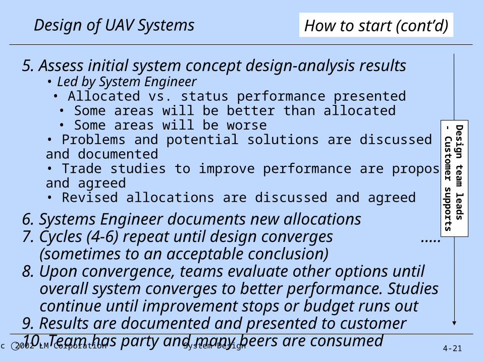
5. Assess initial system concept design-analysis results• Led by System Engineer• Allocated vs. status performance presented• Some areas will be better than allocated• Some areas will be worse
• Problems and potential solutions are discussed and documented• Trade studies to improve performance are proposed and agreed• Revised allocations are discussed and agreed
6. Systems Engineer documents new allocations7. Cycles (4-6) repeat until design converges
….. (sometimes to an acceptable conclusion)8. Upon convergence, teams evaluate other options until
overall system converges to better performance. Studies continue until improvement stops or budget runs out
9. Results are documented and presented to customer10. Team has party and many beers are consumed
4-21
Design of UAV Systems
System Design c 2002 LM Corporation
How to start (cont’d)D
esign
team lead
s- C
usto
mer su
pp
orts
4-22
Design of UAV Systems
System Design c 2002 LM Corporation
You should now understand the concept of system design
1. Design follows requirements
2. Requirements define what a system needs to do as appropriate for each design phase
3. Requirements do not document a design on an after-the-fact basis
4. Design solutions are traded to ensure that they reflect the best balance of cost, risk and performance
5. Design solutions (and performance) should not be dictated (by the boss or individual designers)
Expectations
Today requirements also evolve with the design
• Even threshold requirements are subjected to trade off studies!
4-23
Design of UAV Systems
System Design c 2002 LM Corporation
Next subject - Student projects
• Next generation tactical UAV (TUAV)- Support army/marine type ground operations
• Maritime search UAV- Support navy/coast guard type operations
• Standoff intelligence, surveillance and reconnaissance (ISR) UAV- Global Hawk follow-on type
• Penetrating ISR UAV- Dark Star follow-on type
• Air-to-ground combat UAV (UCAV)- X45 follow-on type
- You will select one of the five as a semester design project- It will also be the basis for your homework problems
4-24
Design of UAV Systems
System Design 2002 LM Corporation
Next generation TUAV
Forward based operations from 3000 ft paved runway- Provide continuous (24x7) day/night/under weather near real time
ISR coverage of 100 nm x 100 nm operations area- Able to resolve range of ground moving targets to 10 m anywhere
within combat area and transmit detection data within 2 minutes- Able to provide on-demand positive identification of friendly troops vs.
opponent forces (req’d resolution = 10-20 cm) and transmit imagery to base and/or infantry units within 3 minutes of request
- UAV squadron is based within 70 nm of combat areas- Each squadron provides simultaneous support of 10 infantry units,
each operating in 10nm x 10 nm combat area- Ignore survivability effects
Minimum required trades- Communication architecture- Sensor(s) required- Control architecture- Operating altitude(s)- Time on station
- Air vehicle size and numbers- Air vehicle speed(s)- Propulsion type and size- Aspect ratio- Wing Loading
4-25
Design of UAV Systems
System Design 2002 LM Corporation
Next generation TUAV
100 nm
100
nm
Base
70 nm
Area of operations
10 nm
10 n
m
Combat area
50 nm
4-26
Design of UAV Systems
System Design 2002 LM Corporation
Maritime search UAV
• Land based with 5000 foot paved runway- Squadron is based on the coast- Able to provide continuous day/night/all weather near real time
search capability of 100 x 100 nm ocean surveillance area - Able to launch on distress call or operate from loiter during
periods of heightened alert (24 hrs day/7 days a week)- Able to resolve range of 10 sqm moving targets to 10 m within
surveillance area and transmit movement within 2 minutes- Able to put sensors on target anywhere within search area and
transmit image within 15 minutes or less- Able to ID small boat (req’d resolution = 0.75-1.2m) and identify
• Minimum required trades- Communication architecture- Sensor(s) required- Control architecture- Operating altitude(s)- Time on station
- Air vehicle size and numbers- Air vehicle speed(s)- Propulsion type and size- Aspect ratio- Wing Loading
4-27
Design of UAV Systems
System Design 2002 LM Corporation
Maritime search UAV
100 nm
100
nm
Search area
BaseLoiter location(s)?
4-28
Design of UAV Systems
System Design 2002 LM Corporation
Stand off UAV
Land based with 5000 foot paved runway- Provide continuous (24x7) day/night/under weather near real time
ISR coverage of 100 nm x 100 nm surveillance area- Able to resolve range of ground moving targets to 10 m anywhere
within surveillance area and transmit detection data within 2 minutes- Able to provide on-demand positive identification of 0.5m x 0.5m
targets and transmit imagery within 10 minutes - UAV is based within 200 nm of combat area- Ignore survivability effects
Minimum required trades- Communication architecture- Sensor(s) required- Control architecture- Operating altitude(s)- Time on station- Loiter pattern and location
- Air vehicle size and numbers- Air vehicle speed(s)- Propulsion type and size- Aspect ratio- Wing Loading
4-29
Design of UAV Systems
System Design 2002 LM Corporation
Stand off UAV
100 nm
Loiter location(s)? 20
0 n
m
Surveillance area
4-30
Design of UAV Systems
System Design 2002 LM Corporation
Penetrating UAV
Land based with 5000 foot paved runway- Provide continuous (24x7) day/night/under weather near real time
ISR coverage of 100 nm x 100 nm surveillance area- Able to resolve range of ground moving targets to 10 m anywhere
within surveillance area and transmit detection data within 2 minutes- Able to provide on-demand positive identification of 0.5m x 0.5m
targets and transmit imagery within 20 minutes - UAV is based within 200 nm of combat area- Ignore survivability effects
Minimum required trades- Communication architecture- Sensor(s) required- Control architecture- Operating altitude(s)- Time on station- Loiter pattern and location
- Air vehicle size and numbers- Air vehicle speed(s)- Propulsion type and size- Aspect ratio- Wing Loading
4-31
Design of UAV Systems
System Design 2002 LM Corporation
Penetrating UAV
100 nm
200
nm
Surveillance area
Loiter location(s)?
4-32
Design of UAV Systems
System Design 2002 LM Corporation
Air-to-ground UCAV
Land based with 5000 foot paved runway- Provide continuous (24x7) day/night/under weather ground attack
capability against 10 sqm ground moving targets within a 100 nm x 200 nm operating area
- Able to put eight 500 lb precision guided (GPS) bombs on operator selected target within15 minutes
- Able to provide operator with positive identification of 0.3m x 0.3 m resolution targets prior to weapons release
- UCAV is based within 200 nm of combat area- Ignore survivability effects
Minimum required trades- Communication architecture- Sensor(s) required- Control architecture- Operating altitude(s)- Time on station- Loiter pattern and location
- Air vehicle size and numbers- Air vehicle speed(s)- Propulsion type and size- Aspect ratio- Wing Loading
4-33
Design of UAV Systems
System Design 2002 LM Corporation
Air-to-ground UCAV
200 nm
200
nm
Target area
100
nm
Loiter location(s)?
4-34
Design of UAV Systems
System Design c 2002 LM Corporation
We will use a one continuous example problem throughout the semester to demonstrate:
(1) How to approach the problem(2) How to apply design and analysis methods
First half focus: System requirements analysis- Target coverage- Time on station and response time- Sensor size and performance- Communications architecture and bandwidth- Payload type, size and performance- Manpower
Second half focus: Air vehicle and design trades- Air vehicle size and configuration trades- Propulsion cycle and trades- Performance and technology- Effectiveness- Cost effectiveness and system optimization
Example problem
• Predator follow-on type• Land based with 3000 foot paved runway
- Mission : provide continuous day/night/all weather, near real time, monitoring of 200 x 200 nm area
- Basing : within 100 nm of surveillance area- Able to resolve range of 10m sqm moving targets to 10m and
transmit ground moving target (GMT) data to base in 2 minutes - Able to provide positive identification of selected 0.5m x 0.5 m
ground resolved distance (GRD or “resolution”) targets within 30 minutes of detection
- Communication architecture- Sensor(s) required- Control architecture- Operating altitude(s)- Time on station- Loiter pattern and location
4-35
Design of UAV Systems
System Design c 2002 LM Corporation
Example - surveillance UAV
- Air vehicle size and numbers- Air vehicle speed(s)- Propulsion type and size- Aspect ratio- Wing Loading
4-36
Design of UAV Systems
System Design c 2002 LM Corporation
Surveillance UAV
200 nm
Loiter location(s)?
100
nm
Surveillance area
200
nm
4-37
Design of UAV Systems
System Design c 2002 LM Corporation
Homework assignment
(1) Select one of the 5 student projects- The one that interests you most- All are of approximately equal complexity
• During the first half of the semester you will work as a team of one to define your overall system- During the second half, you will work on (or lead) a
team to define the air vehicle and optimize the system• Team projects (and leads) will be based on mid-term
presentations- The most feasible projects will be selected for
continuation(2) Send Egbert a “capability” email (1 page max)
a. Which project you would like to work onb. Why you want to work on itc. What unique skills and capabilities you think you