45
1 Description of Chemical Processes CHEE 2404
| Date post: | 24-Oct-2015 |
| Category: |
Documents |
| Upload: | joneshutauruk |
| View: | 31 times |
| Download: | 1 times |

1
Description of Chemical Processes
CHEE 2404

2
Objectives
• To be able to define different streams in a process.
• To describe the meaning of standard abbreviations and symbols used on process flowsheets.
• Write a description of a process flowsheet.• Draw a process flowsheet from a written
description.

3
Introduction
• What is a Process?• A process is some operation carried out to modify
input(s) to output(s) – based on physical and/or chemical changes
ProcessInputs
“feeds”
Outputs
“products”

4
1. Specification of equipment, and materials and their subsequent arrangement into processes which control the environment of a chemical or physical operation to achieve a desired output.
2. The analysis of the operation of existing chemical or physical processes in order to alter the processing operation to achieve a desired result.
Process design vs. Process analysis
Your role in the chemical process

5
Both problems require analysis and design functions.Example:An oil fired boiler in an oil refinery is not producing the required amount of steam. The chemical engineer first analyses the boiler to determine the nature of the problem (like a diagnosis, this is the analysis).
Then the engineer proposes a solution which may involve some design. So for example, If the poor performance was caused by inadequate supply of air for combustion, the engineer would determine the correct amount of air, and to supply the amount of air s/he might have to design (or specify) a new air blower.

6
Describing Processes
• Input – output diagram
• Block diagram
• Process Flow Diagram (PFD)

7
Process
ProductsRaw Materials
Block flow diagram

8
Block Flow Diagram
• Group of connected blocks of process units• Lines with arrows connect blocks and represent process
streams• Raw materials enter on the left
• Products exit on the right
• 4 kinds of “process” units:MixersReactorsSplittersSeparators

9
Mixer
butter
C12H22O11
flour
eggs
NaCl
NaHCO3
Chocolate chips
Raw chocolate chipCookie dough
Baked chocolate chipCookiesReactor (Oven)
Raw chocolate chipCookie dough

10
Splitter
4 dozen cookies75% choc chip25% peanut butter
3 dozen cookies75% choc chip25% peanut butter
1 dozen cookies75% choc chip25% peanut butter
Separator
4 dozen cookies75% choc chip25% peanut butter
3 dozen cookies97.5% choc chip2.8% peanut butter
1 dozen cookies8.3% choc chip91.7% peanut butter

11
Flowsheets
The first step in any process design or analysis is the construction of a flowsheet that shows the major material flows and processing steps.
– common flowsheet symbols–common abbreviations
•The flow sheet allows for better visualization and quantification of the process.“A picture is worth a thousand words.”•A process flow sheet is comprised of units, represented by simple shapes like circles or rectangles.

12
Some common flowsheet symbols
Pumps are used to increase a fluids pressure so the fluid will flow from highpressure to low pressure, or used to condense a fluid or increase the speed of a chemical reaction.Gas compressor – a different unit description is used as the fluid responds differently than liquid in a pump (ie increase in pressure causes gas to condense)
Gas expander or turbine is similar but with flows reversed.Valves are needed to control flows between various units.

13
• Combiner and splitter:
• Avoid crossing streams. If streams must cross, you need to indicate whether they mix or not.
streams cross without mixing
Ambiguous streams combine and split

14
Example

15
Classification of processesAn integrated series of operations through which materials and/or energy are converted from one form to another.
Batch process: •has a definite end•material is put in, processed, and discharged•applies to more than just reactors (washing machine for example)
Continuous process •materials enter and leave in uninterrupted streams•periodic shutdown is required•Garden sprinker
Semibatch or Semicontinuous•Some materials are charged/discharged at intervals while some enter/exit continuously•Biotechnology industry, to add nutrients

16
Examples: are these batch, semibatch or continuous? What are the raw materials and products?
1. A coffee maker
2. A home oil furnace
3. An oil refinery
4. A toaster
5. The kidney

17
Processes, plants and pipes
Processing operations are carried out in specially designed vessels (distillation columns, tanks, reactors, etc).
Material is brought to these vessels in pipes or on conveyer belts (example….?) we often refer to these as streams
The lines represent the piping or flow of material, the rectangle represents many physical changes and possibly multiple pieces of equipment.
feed
Net overhead
bottoms
*Directional arrows are important!

18
• A PDF or process flow diagram shows the basics without the inner workings of equipment or the control schemes.
• The concept of the flowsheet is applicable to many industries
• The essential elements are – The different operations that make up the process– The sequence in which these operations occur (ie the
relationship between the operations)

19
Example: flowsheet for a home oil burner heating air in a forced circulation system
Cool air from house Warm air to house
oil Air
Flue gas to chimney
•Rectangle represents the oil burner itself•Two separate air streams: the air circulated to the house
the air used for combustion•The arrows indicate input to the furnace and output from the furnace•The continuous line of the circulated air indicates that it does not mix with the fuel, air and combustion products in the furnace.•You could use this same flowsheet to represent different fuels or products (for example…..?)

20
• How would you modify the flowsheet to show the fan that circulates air to the house, the pump for the oil and the oil storage tank?
• Modify to include the house?

21
Cool airWarm air to house
oil Air
Flue gas to chimney
Storage tank
pump
Fan/blower

22
Cool airWarm air to house
oil Air
Flue gas to chimney
Storage tank
pump
Fan/blower
house

23
• For process analysis: chemical engineer must take a complex flowsheet and reduce it to a description
• For process design: you must draw a flowsheet from a process description.
Exercise: Draw a flowsheet for a home washing machine and a home dryer. Write a description of the process.

24
Draw a flowsheet from the following simplified description of the synthesis of ammonia:
A mixture of hydrogen and nitrogen is fed to a catalytic reactor where some of the hydrogen and nitrogen is converted to ammonia. The reactor effluent is sent to a condenser where all of the ammonia is condensed. The condensed ammonia is sent to product storage. The uncondensed hydrogen and nitrogen are recycled by being mixed with a fresh feed of the same composition. The resulting mixture is fed to the reactor.

25
• Type of process?– Reactor and condenser are continuous– Storage tank is semi-continuous
• Reaction: N2 + 3H2 2NH3

26
A mixture of hydrogen and nitrogen is fed to a catalytic reactor where some of the hydrogen and nitrogen is converted to ammonia. The reactor effluent is sent to a condenser where all of the ammonia is condensed. The condensed ammonia is sent to product storage. The uncondensed hydrogen and nitrogen are recycled by being mixed with a fresh feed of the same composition. The resulting mixture is fed to the reactor.
•Step 1 is the feed to the reactor:
reactor“feed”N2
H2
“effluent” NH3
N2
H2

27
A mixture of hydrogen and nitrogen is fed to a catalytic reactor where some of the hydrogen and nitrogen is converted to ammonia. The reactor effluent is sent to a condenser where all of the ammonia is condensed. The condensed ammonia is sent to product storage. The uncondensed hydrogen and nitrogen are recycled by being mixed with a fresh feed of the same composition. The resulting mixture is fed to the reactor.
•Step 2 is to purify the product:
reactor“feed”N2
H2“effluent” NH3
N2
H2
condenser
NH3
liquid

28
A mixture of hydrogen and nitrogen is fed to a catalytic reactor where some of the hydrogen and nitrogen is converted to ammonia. The reactor effluent is sent to a condenser where all of the ammonia is condensed. The condensed ammonia is sent to product storage. The uncondensed hydrogen and nitrogen are recycled by being mixed with a fresh feed of the same composition. The resulting mixture is fed to the reactor.
•Step 3 is to send product to storage:
reactor“feed”N2
H2“effluent” NH3
N2
H2
condenser
NH3
liquid
Storagetank

29
A mixture of hydrogen and nitrogen is fed to a catalytic reactor where some of the hydrogen and nitrogen is converted to ammonia. The reactor effluent is sent to a condenser where all of the ammonia is condensed. The condensed ammonia is sent to product storage. The uncondensed hydrogen and nitrogen are recycled by being mixed with a fresh feed of the same composition. The resulting mixture is fed to the reactor.
•Step 4 is to recycle unreacted feeds:
reactor“feed”N2
H2“effluent” NH3
N2
H2
condenser
NH3
liquid
Storagetank
N2, H2
recycle
purge

30
Process Variables
The variables that describe the condition of a process fall into two categories:
• Extensive variables: which depend on the size of the system (mass, volume)
• Intensive variables: do not depend on the size of the system (e.g. T, p, , mass and mole fractions)
Often on a process flowsheet we would want to specify process variables (size and temperature of condenser for example)
31
Flowsheet conventions
• Process flowsheet: shows the essential elements of the process (operations and sequence). Sometimes information on energy and mass flows are placed on the flowsheet near the streams or n an adjoining table.
• Process Control Flowsheet: shows the basic instrumentation necessary to control the process and its utilities.
• Engineering flowsheets: a series of flowsheets that show all the data required to specify the process equipment. Typically consists of separate flowsheets:
– Piping flowsheet shows all pipes and equipment with sizes and other necessary specifications. This flowsheet contains one symbol for each piece of equipment in the process.
– Instrumentation flowsheet shows the relationship of every instrument to the process (often combined with piping flowsheet in a P&ID)
– Utility flowsheet shows the relationship of the utilities (steam, water, air electricity) to the process and specifies pipe sizes etc.
– Plot plan show a plan view of the plant giving the physical arrangement of the equipment.

32
Instrumentation and Control
• Instruments are used to sense process variables and drive control valves.
• These are denoted on P&IDs by circles with letters:
• Valves are connected by solid lines to the point where variables are measured, and by dotted lines to the equipment they control
LC FRC
FRC

33
As 1st letter As 2nd letter As 3rd letter
A analyzer Alarm Alarm
C - controller controller
F flow - -
I - indicator -
L Level/liquid level -
P Pressure - -
R - Recorder -
T Temperature - -
V - - Valve
D Differential Differential -
r ratio ratio -
Instrumentation symbols

34
• First letter describes the variable sensed by the instrument: Pressure (P), Temperature (T), Flow (F), level or liquid level (L or LL), composition (A)
• The second and third letters describe the action taken: Record ( R), Indicate (I), Sound an alarm (A), or Control (C )
• Explain the symbols:
LC FRC
35

36
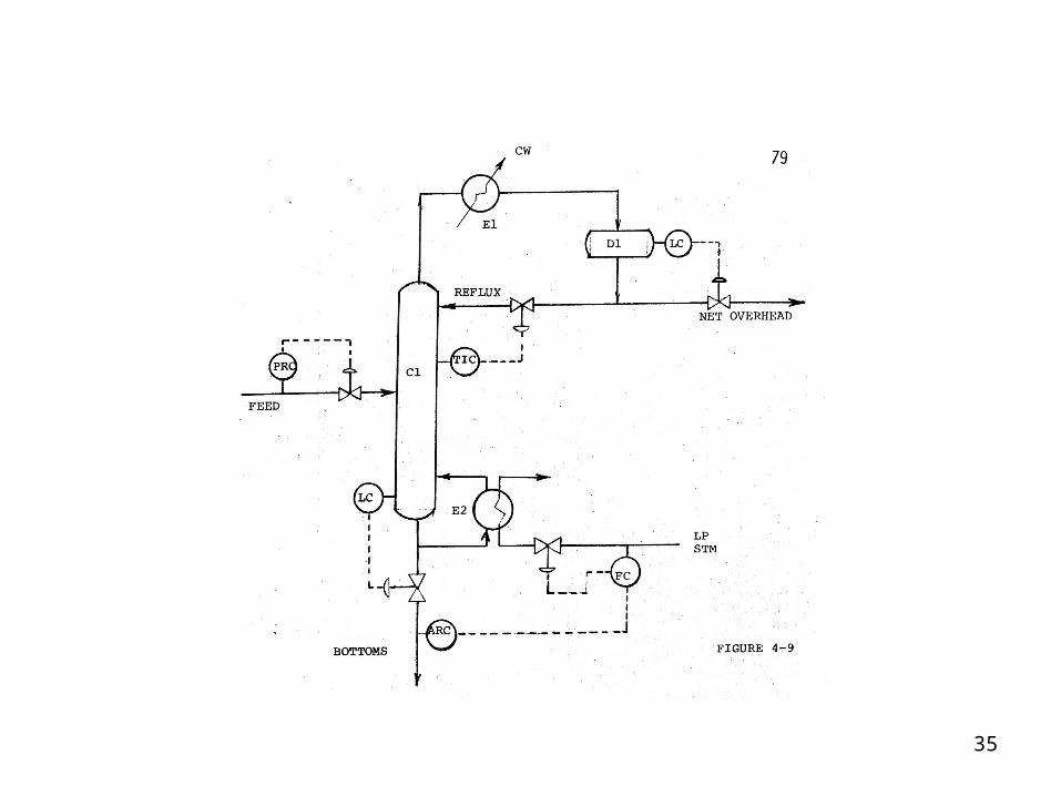
Description
• Main pieces of equipment are the column (C1), accumulator drum (D1), reboiler (E2) and condenser (E1).
• The distillation column (C1) separates the feed stream according to volatility into overhead and bottoms products.
• The heat exchangers (E1) and (E2) condense the overhead vapours and partially vaporize the liquid from the bottom of the column.
• The drum (D1) accumulates the condensed liquid and also accommodates surges in overhead product rate.
• Control elements are shown by circles and dashed lines.

37
Control elements
• The rate of bottoms withdrawal is controlled by the liquid level in the bottom of the column. When the level rises the valve is opened to increase the withdrawal rate and thus lower the level.
• The net bottoms flow is controlled by an analyzer (with recorder) which sets the flow controller on the steam to the reboiler to maintain the bottoms composition within specified limits.
• The net overhead is withdrawn from the drum on level control (ie when the level in D1 rises the valve is opened). This keeps the level in the tank within a preset upper and lower limits.
• The rate at which reflux is returned to the column is controlled by the Temperature at a particular point in the column, when this temperature rises the valve is opened and more reflux flows to the column. This instrument is an indicator as well as a controller so it sends a signal proportional to the temperature to a readout instrument in the control room.
• The column is feed controlled by an FRC.

38
Exercise: Using the flowsheet and description for production of methyl methacrylate and answer the following questions.1. How many reactors are there?2. How many heat exchangers are shown?3. How is the temperature controlled in the hydrolysis kettle?4. How many pumps are shown?5. Why is the inhibitor added?6. Which streams are bypass streams (indicate by stream number)7. Which streams are recycle streams (indicate by stream number)8. The bottoms from the CH3Oh recovery column is water. Where
did this water enter the process?9. What are the main species present in the extraction column
bottoms?10. Is the first reaction endothermic or exothermic? How do you
know?11. How is the heat required for the second reaction supplied?

39

40
Methyl methacrylate is a mononomer used in the production of polymeric materials.It is manufactured in a 2 step chemical process starting with acetone cyanohydrin and 98% sulfuric acid:
Acetone cyanohydrin and concentrated sulfuric acid are pumped into a cooled hydrolysis kettle to make the intermediate.
The stream leaving the kettle is dehydrated at steam temperature.
After cooling it goes to an esterification kettle where it is reacted with methanol continuously. To prevent polymerization inhibitors are added at various points in the process.
The esterified stream is pumped to the acid stripping column. Methyl methacrylate methanol and some water come overhead while the residue, made up of sulfuric acid, ammonium bisulfate, and water, is sent to the ammonium sulfate plant.

41
• The overhead stream from the acid stripping column enters a rectifier column where methyl methacrylate with some methanol comes over the top, is condensed, and sent to the wash column.
• The bottoms from the rectifier, containing methanol and water are sent to a methanol recovery column. Recovered methanol is recylced to the esterification kettle.
• The water solution leaving the bottom of the column, containing some methyl methacrylate and methanol, is recycled to the rectifier column for recovery.
• Crude methyl methacrylate (free from methanol) comes off the top of the wash column. This crude material is shipped to another plant for further purification by distillation.
• The inhibitor introduced in processing is sufficient for shipment of crude methyl methacrylate.

42
1. How many reactors are there?• 2 reactors: hydrolysis kettle and esterification kettle
2. How many heat exchangers are shown?– 5 (not including the steam jacket and reflux condenser)
3. How is the temperature controlled in the hydrolysis kettle?– Some of the kettle contents are removed, cooled and returned to the
kettle
4. How many pumps are shown?– 8
5. Why is the inhibitor added?– To prevent polymerization
6. Which streams are bypass streams (indicate by stream number)– None

43
7. Which streams are recycle streams (indicate by stream number)– 15,5,12,17
8. The bottoms from the CH3Oh recovery column is water. Where did this water enter the process?– Water enters in extraction column, acid stripping column and
CH3OH column, stream 6 and stream 2 if the acid is not 100%.
9. What are the main species present in the extraction column bottoms?– Water, methanol, methyl methacrylate
10. Is the first reaction endothermic or exothermic? How do you know?– Exothermic. Cooling is provided for the hydrolysis kettle
11. How is the heat required for the second reaction supplied?– By the condensation of steam.

44
Checklist of Data Normally Included on Flowsheets (detailed diagrams)
1. Process lines (bypass essential to an understanding of the process)
2. All process equipment. Spaces are indicated by letter symbols or notes
3. Major instrumentation essential to process control and understanding of the flowsheet
4. Valves essential to understanding the flowsheet.5. Design basis, including a stream factor6. Temps, pressures and flow quantities7. Weight and/or mole balance showing compositions,
amounts and other properties of principal streams8. Utilities requirements summary

45
9. Data for particular equipment:a) Compressors – SCFM (60F 14 psia), P, # stagesb) Drives – connected HP, utilitiesc) Drums and tanks – ID or OD, length, impt, internalsd) Exchangers- ft2, Btu/hr, T and flows, Shell, Tube e) Furnaces – kBtu/hr, T in and out, fuelf) Pumps – gpm, P, HP, type, driveg) Towers - # and type of plates, H and type of packing,
info on trays where fluids enter and leave, ID or OD, length


