4 Fire Detection 4.1 Summary................................................................................................63 4.2 Basics.....................................................................................................65 4.2.1 Outbreak of a Fire ...................................................................................65 4.2.2 Development of a Fire.............................................................................66 4.2.3 Fire Phenomena......................................................................................67 4.2.4 Types of Fire ...........................................................................................69 4.2.5 Fire Detection System.............................................................................70 4.3 Fire Detectors ........................................................................................72 4.3.1 Detection Principles ................................................................................72 4.3.2 Detection Reliability.................................................................................84 4.3.3 Networking Technologies........................................................................92 4.4 Selecting the Appropriate Fire Detector.............................................94 4.4.1 Consideration of the Type of Fire............................................................94 4.4.2 Considering the Room Height.................................................................97 4.4.3 Considering Ambient Conditions.............................................................97 4.4.4 Considering Prevailing Deceptive Phenomena ......................................98 4.4.5 Fire Detectors for Explosion-Hazard Areas ............................................98 4.4.6 Summary.................................................................................................99 4.5 Number and Positioning of Fire Detectors.......................................103 4.5.1 Basics....................................................................................................103 4.5.2 Manual Call Points ................................................................................105 4.5.3 Point-type Smoke Detectors .................................................................105 4.5.4 Point-type Heat Detectors.....................................................................107 4.5.5 Linear Smoke Detectors .......................................................................108 4.5.6 Aspirating Smoke Detectors .................................................................110 4.5.7 Flame Detectors....................................................................................116
4.6 Fire Detection Control Unit and Peripheral System ........................119 4.6.1 Control Unit ...........................................................................................120 4.6.2 Peripheral System.................................................................................123 4.6.3 Commissioning......................................................................................128 4.6.4 Selecting the Suitable Fire Detection Control Unit................................134 4.7 Linear Heat Detection Systems .........................................................135 4.7.1 Detection Principles ..............................................................................136 4.7.2 Selecting the Suitable System ..............................................................139 4.8 Planning ...............................................................................................140 4.8.1 Object-independent Planning................................................................140 4.8.2 Object-dependent Planning ..................................................................143 4.9 Installation, Commissioning and Acceptance .................................150 4.9.1 Installation .............................................................................................150 4.9.2 Commissioning......................................................................................151 4.9.3 Acceptance ...........................................................................................151 4.10 Profitability and System Evaluation..................................................152 4.10.1 Cost Blocks ...........................................................................................152 4.10.2 Service Life ...........................................................................................153 4.10.3 Extensions and Modernization..............................................................154 4.10.4 False Alarms .........................................................................................155 4.10.5 Conclusion ............................................................................................155
The task of an automatic fire detection system is to detect fire as early as possible, to alarm and activate the preprogrammed control functions. State-of-the-art fire detection systems are capable of detecting fire extremely early and thus of mini-mizing the damage that may be caused by fire. By an optimal product selection and appropriate knowledge it is possible to set up systems that virtually rule out false alarms. A fire detection system consists of the control unit, the peripherals such as fire detectors and contacts, as well as alarm and control devices activated by the control unit. In selecting, setting and positioning fire detectors, it is crucial to consider – in addition to the actual prevailing risk – the type of fire to be expected, the room height, ambient conditions such as air changes and possible deceptive phenom-ena. In high-risk areas, multisensor fire detectors with state-of-the-art signal proc-essing are used more and more frequently. For medium and lower risks, usually optical smoke detectors with conventional signal processing (algorithm technology) are applied. State-of-the-art fire detectors allow an exact configuration of the detector behavior, which meets the environmental conditions and the prevailing deceptive phenom-ena. A fire detector in a hospital room must respond in a completely different way than a fire detector in a foundry. When arranging the fire detectors, one must be sure that the fire phenomena (smoke, heat, radiation, gas) reach the fire detectors, giving special consideration to the ceiling’s construction (e.g. the ceiling joists, special roof or ceiling shapes), and a possible room division by alcoves, furniture or fixtures and fittings. In rooms where strong deceptive phenomena occur, the ideal arrangement of the fire detectors is of central significance. Even small changes of the detector position bring about massive improvements of the immunity to deception, without reducing the detection reliability. In selecting the fire detection control unit, user-friendliness, a high degree of flexi-bility and a very high degree of fail-safe operation must be taken into consideration. The control unit is the point of interaction between people and the system and must thus make easy and intuitive alarm and fault processing possible. High flexibility in networking and parameter setting facilitate extensions and the adaptation of the system behavior to a change of customer requirements.
The availability of a fire detection system is crucial, which is why emergency power supply and an integrated emergency operating function are mandatory, making fire alarms possible in spite of a failure to a module or a power failure. For economic reasons, a fire detection system's technology is chosen according to the requirements and the specific risk situation. For an office building, a fire detec-tion system with manual call points and optical smoke detectors with normal signal processing is usually sufficient, but if production facilities in the chemical industry shall be protected, for example, the use of advanced technology is a must. A comprehensive product portfolio, highly reliable fire detectors with multisensor technology and the use of an exceptional logic, high flexibility of the fire detection control unit and its connection to the danger management system are topics to be considered in setting up a fire detection system.
Minimize damage through reliable and early detection
The knowledge of the outbreak of a fire and its development is decisive for fire prevention and fire fighting. To ensure reliable, early detection in the case of fire, it is equally important to be familiar with the different fire phenomena and the possi-ble types of fire. The following four topics will be handled in detail hereinafter: − outbreak of a fire − development of a fire − fire phenomena − types of fire Section 4.2.5 shows the setup of a fire detection system and the aspects to be considered in its planning and implementation.
4.2.1 Outbreak of a Fire
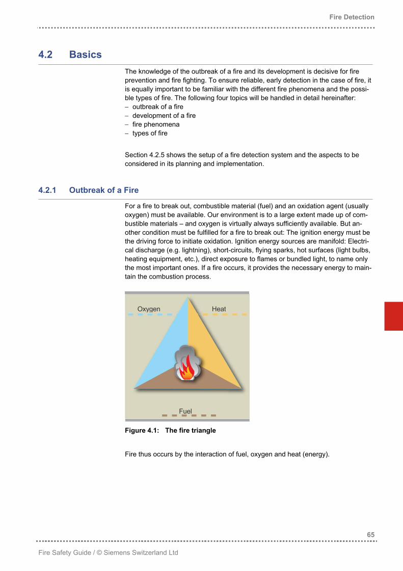
For a fire to break out, combustible material (fuel) and an oxidation agent (usually oxygen) must be available. Our environment is to a large extent made up of com-bustible materials – and oxygen is virtually always sufficiently available. But an-other condition must be fulfilled for a fire to break out: The ignition energy must be the driving force to initiate oxidation. Ignition energy sources are manifold: Electri-cal discharge (e.g. lightning), short-circuits, flying sparks, hot surfaces (light bulbs, heating equipment, etc.), direct exposure to flames or bundled light, to name only the most important ones. If a fire occurs, it provides the necessary energy to main-tain the combustion process.
Figure 4.1: The fire triangle
Fire thus occurs by the interaction of fuel, oxygen and heat (energy).
Apart from explosion-type processes, a fire normally develops more or less quickly, depending on the combustible material. As fuel and oxygen are sufficiently avail-able at the beginning of the fire development, it is to a large extent determined by the available energy. Especially a flaming fire releases a lot of energy resulting in exponential fire growth at this stage.
Figure 4.2: Typical fire development
As shown in Figure 4.2, most fires pass through the following phases and events:
Flashover
• Early stage: The incipient fire can be extinguished with a few deciliters of water; little visible smoke occurs, but especially invisible aerosols are generated.
• Smoldering phase: In this phase, the fire can be extinguished by means of a fire extinguisher or a similar extinguishing agent. Visible, partly dense smoke occurs. Usually, combustion is incomplete, which is why rather a lot of (toxic) CO is produced in this phase.
• Flaming phase: We are faced with an open fire to be fought by the fire brigade. As enough energy is available, the combustion process is rather complete, re-sulting in a high production of CO2.
• Flashover: The transition between an open, flaming fire and a total fire is called flashover. This is the explosive fire spread, taking place exactly at the point when the gases and aerosols produced during the previous phases ignite and carry the fire into all rooms already penetrated by the smoke gases.
• Total fire: In this phase, the fire has reached larger building parts. In most cases, the building or fire sector can no longer be saved and the fire brigades concentrate their efforts on the protection of neighboring buildings and fire sec-tors.
Fire detection must occur as early as possible, so that intervention can start before the flashover. Incipient fires should thus be detected in the early stage or in the smoldering phase at the latest, so that there is enough intervention time left. The problem is that the early stage and the smoldering phase can be of completely different intensity and duration. Some smoldering fires may continue to smolder for hours or even days before an open fire occurs. With liquid fires, there is no smoldering phase at all; they directly develop flames. With such fires, the intervention time is extremely short. Usually, damage can only be limited by an automatic extinguishing system. Of course, there are other possi-bilities, such as constructive measures, to slow down fire spread, thus prolonging the intervention time – but this is usually very expensive. Conclusion: The earlier a fire is detected, the more time there is for fire fighting, and the less damage occurs. Earliest possible detection is thus the key to minimiz-ing damage and winning precious intervention time.
4.2.3 Fire Phenomena
Fire phenomena are physical values that are subject to measurable change in the development of a fire (e.g. temperature increase, light obscuration or flames). The processes in material combustion can be principally viewed from the perspec-tive of a conversion of energy and substances. The energetic conversion releases energy into the environment. The substantial conversion produces – depending on the substances present at the seat of fire – products in any physical state, ranging from non-toxic to highly toxic. The figure below indicates the concomitant phenomena of a fire with the associ-ated fire phenomena (in parentheses).
Figure 4.3: Schematic representation of fire phenomena
The energetic conversion releases energy by radiation and convection. The range of radiation released during a fire can be divided, by wavelength, into ultraviolet (UV), visible light and infrared (IR). Energy release by convection essentially takes place through the ambient air. First, the kinetic energy of the air molecules is increased, resulting in a temperature increase. The associated expansion leads to an upward air flow. Due to this flow, cooler air and thus oxygen is guided to the fire seat. These processes can also lead to periodic pressure fluctuations that are perceived as sound in certain frequency ranges (e.g. the typical crackling of a fire). The conversion of substances taking place in a fire is characterized by the various chemical reactions that can occur at the seat of fire, depending on the substances present.
The substantial conversion of a fire is determined by the different chemical reac-tions that may go on at the seat of fire. The solid or liquid conversion products either remain at the fire seat (e.g. ashes) or are distributed into the direct environ-ment of the fire. In the latter case, they form a so-called aerosol, as finely distrib-uted solid or liquid suspended matters mixing with the ambient air. Gaseous conversion products always spread through the air.
4.2.4 Types of Fire
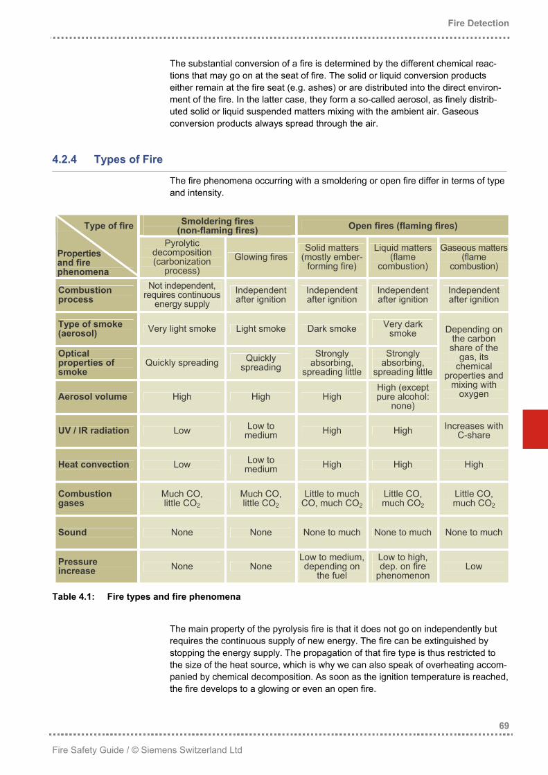
The fire phenomena occurring with a smoldering or open fire differ in terms of type and intensity.
Smoldering fires (non-flaming fires) Open fires (flaming fires) Type of fire
Properties and fire phenomena
Pyrolytic decomposition (carbonization
process) Glowing fires
Solid matters (mostly ember-
forming fire)
Liquid matters (flame
combustion)
Gaseous matters(flame
combustion)
Combustion process
Not independent, requires continuous
energy supply Independent after ignition
Independent after ignition
Independent after ignition
Independent after ignition
Type of smoke (aerosol) Very light smoke Light smoke Dark smoke Very dark
smoke
Optical properties of smoke
Quickly spreading Quickly spreading
Strongly absorbing,
spreading little
Strongly absorbing,
spreading little
Aerosol volume High High High High (except pure alcohol:
none)
Depending on the carbon share of the
gas, its chemical
properties and mixing with
oxygen
UV / IR radiation Low Low to medium High High Increases with
C-share
Heat convection Low Low to medium High High High
Combustion gases
Much CO, little CO2
Much CO, little CO2
Little to much CO, much CO2
Little CO, much CO2
Little CO, much CO2
Sound None None None to much None to much None to much
Pressure increase None None
Low to medium, depending on
the fuel
Low to high, dep. on fire
phenomenon Low
Table 4.1: Fire types and fire phenomena
The main property of the pyrolysis fire is that it does not go on independently but requires the continuous supply of new energy. The fire can be extinguished by stopping the energy supply. The propagation of that fire type is thus restricted to the size of the heat source, which is why we can also speak of overheating accom-panied by chemical decomposition. As soon as the ignition temperature is reached, the fire develops to a glowing or even an open fire.
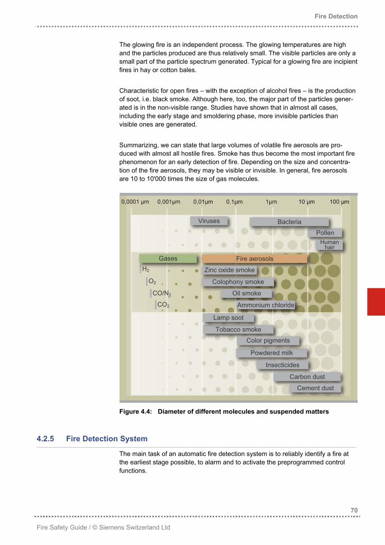
The glowing fire is an independent process. The glowing temperatures are high and the particles produced are thus relatively small. The visible particles are only a small part of the particle spectrum generated. Typical for a glowing fire are incipient fires in hay or cotton bales. Characteristic for open fires – with the exception of alcohol fires – is the production of soot, i.e. black smoke. Although here, too, the major part of the particles gener-ated is in the non-visible range. Studies have shown that in almost all cases, including the early stage and smoldering phase, more invisible particles than visible ones are generated. Summarizing, we can state that large volumes of volatile fire aerosols are pro-duced with almost all hostile fires. Smoke has thus become the most important fire phenomenon for an early detection of fire. Depending on the size and concentra-tion of the fire aerosols, they may be visible or invisible. In general, fire aerosols are 10 to 10'000 times the size of gas molecules.
Viruses Bacteria
Pollen Human
hair
Gases Fire aerosols H2 Zinc oxide smoke
O2 Colophony smoke
CO/N2 Oil smoke
CO2 Ammonium chloride
Lamp soot
Tobacco smoke
Color pigments
Powdered milk
Insecticides
Carbon dust
Cement dust
Figure 4.4: Diameter of different molecules and suspended matters
4.2.5 Fire Detection System
The main task of an automatic fire detection system is to reliably identify a fire at the earliest stage possible, to alarm and to activate the preprogrammed control functions.
Figure 4.5: Setup and function of a fire detection system
The periphery comprises all field elements acquiring the actual state on site, which is transmitted to the control unit in the form of hazard levels. The intelligent, auto-matic fire detectors detect and analyze the different fire phenomena on site and automatically report prevailing hazards to the control unit. Manual call points serve for the direct alarm activation by people present in the danger zone. Automatic contacts (e.g. from an activation of a sprinkler extinguishing system) report a fire alarm indirectly. The fire detection system is monitored, controlled and operated by the control unit, which evaluates the hazard messages from the peripheral devices and activates alarm and fire control installations. Additionally, it serves for operating the fire detection system itself. The measures initiated by the control unit serve for alarm and intervention. Optical and acoustic alarm devices inform the people in the building and those responsible for the building and call the fire brigade. Controls activate smoke extraction sys-tems and stationary extinguishing systems. Optical escape route guidance and voice alarm safely evacuate people from the building.
The following categories of fire detectors are basically distinguished: • Non-automatic fire detectors: Manual call points are non-automatic fire detec-
tors that have to be activated by a person in the case of fire. • Semi-automatic fire detectors: We speak of semi-automatic fire detectors
when a fire detector may recognize a fire but alarm is activated manually. These are usually camera systems equipped with appropriate software, which are ca-pable of detecting changes to the recorded images, for example the generation of smoke or open fires. As the reliability of these systems is presently not suffi-cient to activate actions such as the direct alarm of the fire brigade or extinguish-ing activation, these systems are usually semi-automatic. The system alerts people to a possible danger, while the actual alarm must still be verified.
• Automatic fire detectors: These most frequently used fire detectors capture fire phenomena such as smoke, heat, flames or gas and activate an alarm via the control unit in the case of fire.
• Fire detectors for special applications: For applications with an increased fire risk, where a normal fire detector cannot be used for different reasons, special detectors are required. In mining or heavy industry, very robust systems are re-quired that are capable of reliably detecting fires under extreme environmental conditions. For example, sparks in transport ducts used in the textile industry must be detected and appropriate measures must be initiated immediately, as otherwise devastating consequences can occur. Normal fire detectors react much too slow for such applications – systems reacting within a few milliseconds are required here.
The following chapters exclusively handle detection principles, detection reliability and the available networking technologies of automatic fire detectors.
4.3.1 Detection Principles
A fire detector must be capable of detecting at minimum one fire phenomenon (smoke, heat, radiation, gas) reliably at an early stage. Increasingly, state-of-the-art fire detectors are used that can detect several phenomena at once. These fire detectors generally have a significantly better response behavior and are highly immune to deception. Of course, a smoke detector’s sensitivity does not only depend on the detection principle but also on the specific detector design, the type of smoke and other environmental factors, such as air humidity, etc. To be able to exactly determine the sensitivity of a detector, a standardized procedure is used (see also section 4.4.1.1).
Most fires produce smoke, which can be detected by relatively simple detectors. This is also the reason why state-of-the-art fire detection systems consist to more than 80% of smoke detectors. Based on the great significance of this fire detection principle, new and improved point detectors have been continually developed in the past. The most important principles are scattered light, extinction (light absorption) and ionization. Until about 1990, ionization was the most important principle. Today, however, most point detectors work according to the scattered light principle. People speaking of optical smoke detectors today usually refer to scattered light smoke detectors.
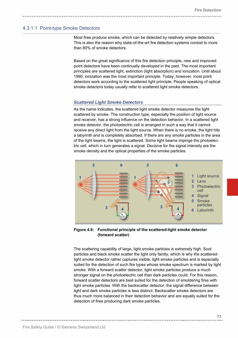
Scattered Light Smoke Detectors As the name indicates, the scattered light smoke detector measures the light scattered by smoke. The construction type, especially the position of light source and receiver, has a strong influence on the detection behavior. In a scattered light smoke detector, the photoelectric cell is arranged in such a way that it cannot receive any direct light from the light source. When there is no smoke, the light hits a labyrinth and is completely absorbed. If there are any smoke particles in the area of the light beams, the light is scattered. Some light beams impinge the photoelec-tric cell, which in turn generates a signal. Decisive for the signal intensity are the smoke density and the optical properties of the smoke particles.
Figure 4.6: Functional principle of the scattered-light smoke d(forward scatter)
The scattering capability of large, light smoke particles is extremelyparticles and black smoke scatter the light only faintly, which is whylight smoke detector rather captures visible, light smoke particles ansuited for the detection of such fire types whose smoke spectrum issmoke. With a forward scatter detector, light smoke particles produstronger signal on the photoelectric cell than dark particles could. Fforward scatter detectors are best suited for the detection of smoldelight smoke particles. With the backscatter detector, the signal diffelight and dark smoke particles is less distinct. Backscatter smoke dthus much more balanced in their detection behavior and are equaldetection of fires producing dark smoke particles.
123
45
6
Light source Lens Photoelectric
cell Signal Smoke
particles Labyrinth
73
etector
high. Soot the scattered-d is especially
marked by light ce a much or this reason, ring fires with
Extinction Smoke Detectors The word “extinction” originates from Latin, designating physical processes result-ing in attenuation or obliteration. An extinction smoke detector measures the light attenuation caused by absorption and scattering. A light source is focused on by a photoelectric cell from a certain distance. When there is no smoke, the photoelectric cell measures a signal. When smoke penetrates the space between the light source and the photoelectric cell, the signal measured is slightly reduced. This signal reduction caused by absorption and light scattering is proportional to the smoke density. If the distance between light source and receiver measures only a few centimeters, as it is the case with a point detector, this signal reduction in case of smoke is very low (0.05% to 0.2%). Although the evaluation of such a low signal change is meas-urable with state-of-the-art electronics, the required long-time stability still consti-tutes a great challenge.
Figure 4.7: Functional principle of the extinction smoke detector
The extinction smoke detector detects light and dark, large and small aerosols and is characterized by its uniform response behavior. This detector is suited for the early detection of all fires producing visible smoke.
Ionization Smoke Detector As this detector produces electrically charged particles (ions) from neutral particles, it is called ionization smoke detector. The air between two electrodes, biased by a DC voltage, is ionized, i.e. made conductive, by means of a slightly radioactive radiation source. Due to this ioniza-tion, a weak electric current begins to flow in the sampling chamber. When smoke particles penetrate the sampling chamber, ions attach to the smoke particles, reducing the flow of electricity. This reduction is proportional to the number of smoke particles in the measuring area.
Figure 4.8: Functional principle of the ionization smoke detector
The signal coming from the ionization smoke detector is proportional to the number of smoke particles in the sampling chamber. Ionization smoke detectors are thus particularly suited for the detection of open fires, as such fires produce a large number of small, primarily invisible smoke particles. They are less suited for detect-ing smoldering fires that produce only few, large smoke particles.
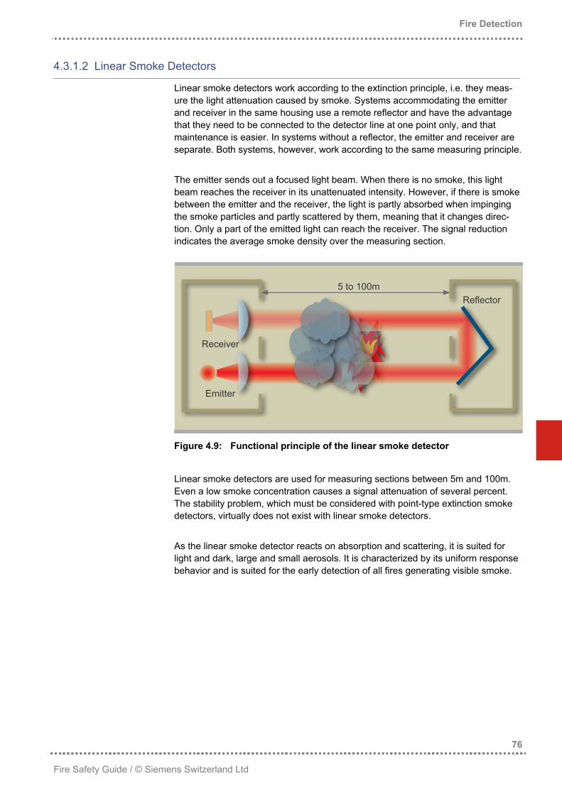
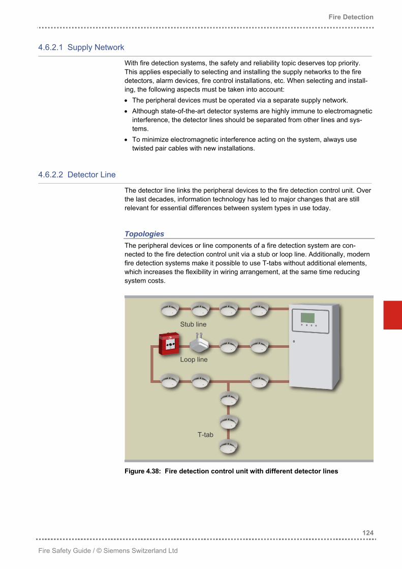
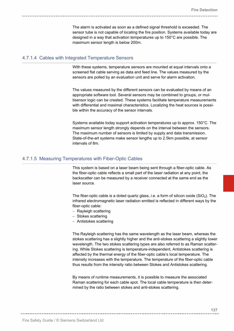
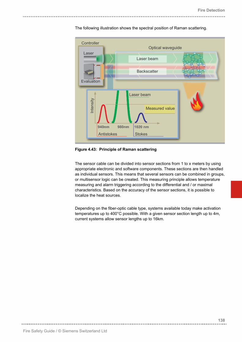
Linear smoke detectors work according to the extinction principle, i.e. they meas-ure the light attenuation caused by smoke. Systems accommodating the emitter and receiver in the same housing use a remote reflector and have the advantage that they need to be connected to the detector line at one point only, and that maintenance is easier. In systems without a reflector, the emitter and receiver are separate. Both systems, however, work according to the same measuring principle. The emitter sends out a focused light beam. When there is no smoke, this light beam reaches the receiver in its unattenuated intensity. However, if there is smoke between the emitter and the receiver, the light is partly absorbed when impinging the smoke particles and partly scattered by them, meaning that it changes direc-tion. Only a part of the emitted light can reach the receiver. The signal reduction indicates the average smoke density over the measuring section.
Figure 4.9: Functional principle of the linear smoke detector
Linear smoke detectors are used for measuring sections between 5m and 100m. Even a low smoke concentration causes a signal attenuation of several percent. The stability problem, which must be considered with point-type extinction smoke detectors, virtually does not exist with linear smoke detectors. As the linear smoke detector reacts on absorption and scattering, it is suited for light and dark, large and small aerosols. It is characterized by its uniform response behavior and is suited for the early detection of all fires generating visible smoke.
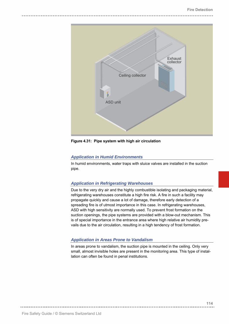
Aspirating smoke detectors are also known as air sampling smoke detection sys-tem or aspiration smoke detection (ASD). In the air sampling smoke detection system, air samples from the monitored area are guided to the detection chamber via a pipe network by means of a powerful suction system.
Figure 4.10: Functional principle of an ASD system
Depending on the manufacturer and the desired sensitivity, the detection chamber accommodates a smoke detector, employing one of the detection principles de-scribed in the following.
Point-type Smoke Detector When no high sensitivity levels are required, the ASD systems are equipped with point detectors. The smoke detectors used for ASD are usually of the same con-struction as normal point detectors, but they are set to the highest sensitivity level.
Cloud Chamber In a closed area, high air humidity is generated by means of a water bath. Then, the smoke particles are guided through this zone. The high humidity condenses on the smoke particles which act as condensation nuclei, resulting in fog. This fog is illuminated with a pulsating LED to determine its density. The higher the density of the fog, the higher the smoke density.
Optical Smoke Detector The sensor consists of a high-energy light source emitting a focused light beam (e.g. laser) and of a receiver. Aerosols in the measuring section deflect the light, which in turn impinges on the receiver's sensor electronics. This signal is evaluated and serves for triggering an alarm.
Xenon Permanently aspirated air is guided through a detection chamber and is illuminated by a xenon lamp over a distance of several centimeters. Smoke particles deflect the beams and produce a correspondingly strong signal due to the relative length of the detection chamber. This signal is evaluated and serves for triggering an alarm. These aspiration smoke detectors require periodic calibration, which is reflected in the expenditures for maintenance. Xenon detectors work according to the scattered light smoke detector principle.
Particle Counter A focused light beam illuminates aspirated air. Smoke particles deflect the beam, which impinges on an optical mechanism and generates an electric pulse. The number of pulses per unit of time is proportional to the smoke density. When the number of particles exceeds a predefined value, an alarm is triggered. With this measuring principle, the air flow must be regulated, as an inconstant air flow would disturb the result.
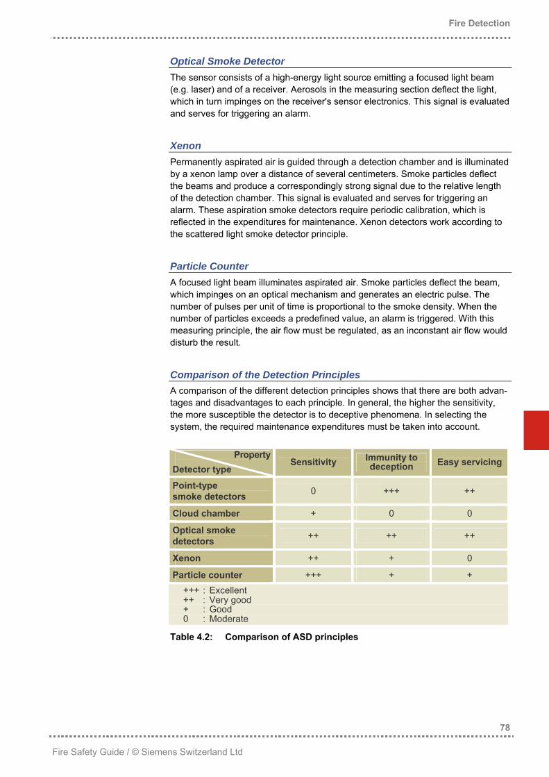
Comparison of the Detection Principles A comparison of the different detection principles shows that there are both advan-tages and disadvantages to each principle. In general, the higher the sensitivity, the more susceptible the detector is to deceptive phenomena. In selecting the system, the required maintenance expenditures must be taken into account.
PropertyDetector type
Sensitivity Immunity to deception Easy servicing
Point-type smoke detectors 0 +++ ++
Cloud chamber + 0 0
Optical smoke detectors ++ ++ ++
Xenon ++ + 0
Particle counter +++ + + +++ : Excellent ++ : Very good + : Good 0 : Moderate
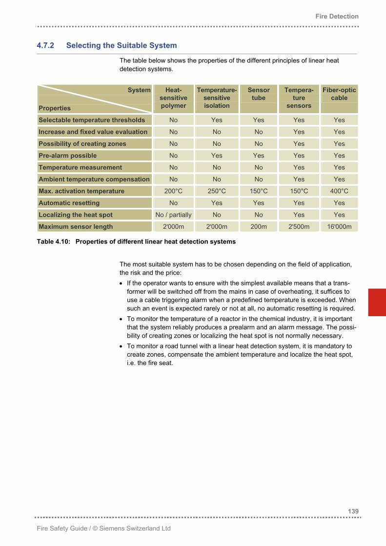
Heat detectors are equipped with a temperature-sensitive element and are only suited for the detection of open fires.
Maximum Temperature Detector With maximum temperature detectors, a maximum temperature is defined. Upon achieving this temperature, the detector switches to alarm mode. These detectors are based on the functional principle of a thermistor (semiconductor element with temperature-sensitive resistor), a fusible element, a bimetal strip or the expansion of a liquid. These detectors only react when a certain temperature is exceeded, independent of the smoke density and other characteristic values. For this reason, maximum temperature detectors are suited for simple applications with a relatively low risk only.
Rate-of-Rise Temperature Detector With the rate-of-rise temperature detector, the temperature increase per unit of time required to trigger an alarm is defined (°C/min). If the measured temperature increase per unit of time exceeds this threshold, an alarm is triggered. Rate-of-rise temperature detectors are usually based on the functional principle of a thermistor. In practice, rate-of-rise temperature detectors are usually designed so that they also switch to alarm mode when a predefined maximum temperature is exceeded – similar to the maximum temperature detector. As the reference value for alarm activation is the rate of rise, these detectors are clearly superior to the maximum temperature detectors. However, they are still restricted to low-risk applications and are only applied in situations where a smoke detector would be subject to massive deceptive phenomena.
4.3.1.5 Linear Heat Detectors
Linear heat detection systems consist of a line-type sensor (a cable with a number of sensors or a tube) and an evaluation unit. These systems are usually applied for special applications only. For this reason, this type of fire detection is handled separately in chapter “Linear Heat Detection Systems” starting on page 135.
4.3.1.6 Flame Detectors
Flame detectors convert the electromagnetic radiation emitted by flames into an electric signal. To rule out faults and deception by sunlight, reflected light, lamps and other light sources as far as possible, the detection range of the detectors is shifted from the visible to the invisible range. Most flame detectors therefore operate in the ultravio-let or infrared range.
Figure 4.11: Application of UV and IR flame detectors
UV Flame Detector UV flame detectors react on the electromagnetic radiation emitted by an open flame in the short-wave range of UV radiation (at a wavelength of approximately 0.2µm).
1 Anode 4 Gas molecules 2 Cathode 5 Signal (electric current) 3 Sampling chamber 6 UV radiation
Figure 4.12: Functional principle of the UV flame detector
High-voltage is applied between the cathode and the anode. As soon as UV rays impinge on the cathode, its surface emits electrons. These electrons hit the gas molecules in the tube, ionizing them and thus initiating a snowball-type electron flow from the anode to the cathode. The result of this process is a striking increase of the current flow that is proportional to the intensity of the UV radiation emitted by the fire.
UV flame detectors are capable of detecting all types of open fires. With appropri-ate sensitivity settings, they are also resistant to sunlight, special fluorescent lamps and spark discharge. However, strong UV sources, such as welding flames, spe-cial lamps, electric arc lamps and ionizing radiation (radioactivity or X-rays) may cause false alarms. Any soiling of the detectors must be avoided as their sensitivity will decrease. Especially an oil film on the sensor lid immediately renders a detec-tor completely inoperable.
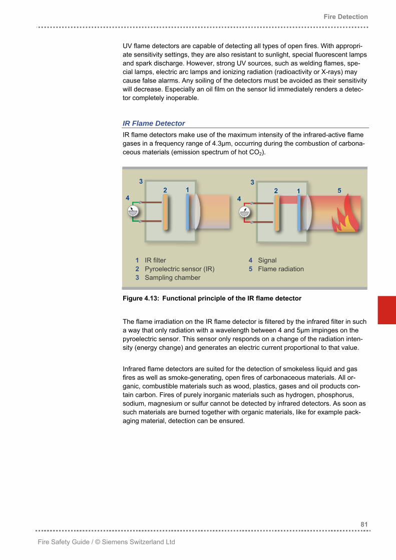
IR Flame Detector IR flame detectors make use of the maximum intensity of the infrared-active flame gases in a frequency range of 4.3µm, occurring during the combustion of carbona-ceous materials (emission spectrum of hot CO2).
1 IR filter 4 Signal 2 Pyroelectric sensor (IR) 5 Flame radiation 3 Sampling chamber
Figure 4.13: Functional principle of the IR flame detector
The flame irradiation on the IR flame detector is filtered by the infrared filter in such a way that only radiation with a wavelength between 4 and 5µm impinges on the pyroelectric sensor. This sensor only responds on a change of the radiation inten-sity (energy change) and generates an electric current proportional to that value. Infrared flame detectors are suited for the detection of smokeless liquid and gas fires as well as smoke-generating, open fires of carbonaceous materials. All or-ganic, combustible materials such as wood, plastics, gases and oil products con-tain carbon. Fires of purely inorganic materials such as hydrogen, phosphorus, sodium, magnesium or sulfur cannot be detected by infrared detectors. As soon as such materials are burned together with organic materials, like for example pack-aging material, detection can be ensured.
The gas sensors used in fire detectors detect either carbon monoxide (CO) that is produced in case of incomplete combustion or carbon dioxide (CO2) produced in case of complete combustion.
CO Detectors With smoldering and glowing fires, combustion is mostly incomplete due to the low temperatures. For this reason, the aerosol particles agglutinate to larger and thus more easily visible parts (strong smoke generation), and a lot of toxic CO gas is produced. Most CO sensors in fire detection work according to the semiconductor principle (for measuring principle, see section 3.4.1 on page 45). However, the market also offers CO sensors based on an electrochemical cell (for measuring principle, see section 3.4.3 on page 47). CO sensors are suited for the early detection of smoldering fires but are only fit for limited detection of open fires. CO sensors based on the semiconductor principle have the disadvantage of high cross-sensitivity (response to different gases) and are strongly influenced by hu-midity. Gases and humidity thus bear an influence on the exact determination of the CO concentration. Electrochemical sensors do not have this disadvantage. However, they have a shorter service life and generate higher maintenance costs (for a comparison, see Table 3.1 on page 49).
CO2 Detectors In contrast to smoldering and glowing fires, open, flaming fires burn a considerable load per unit of time. This is associated with a striking temperature increase and high CO2 production. CO2 is a very durable gas, which is why its chemical detection is rather difficult. To detect CO2, opto-acoustic sensors and infrared absorption sensors are used today (for measuring principles, see sections 3.4.4 and 3.4.5 starting on page 47). CO2 sensors are suited for the detection of open fires but are only fit for limited detection of smoldering fires. CO2 is particularly produced by open fires generating a lot of fire gases. As thermal sensor electronics are much more cost-efficient than CO2 measuring, and as the two phenomena occur largely in parallel, gas measuring hardly has any additional benefits.
Summary CO fire detectors have serious problems in detecting open, flaming fires, while CO2 fire detectors reach their limits when it comes to detecting smoldering fires. In fire detection, pure gas sensors are thus rarely used. For special applications, how-ever, they are used together with other sensor types, mostly in combination with an optical and / or a temperature sensor (multisensor fire detector).
4.3.1.8 Multisensor Fire Detectors
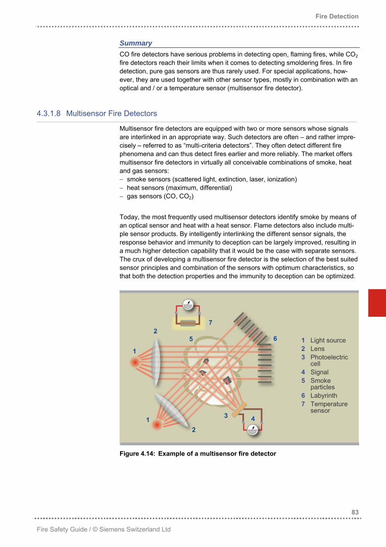
Multisensor fire detectors are equipped with two or more sensors whose signals are interlinked in an appropriate way. Such detectors are often – and rather impre-cisely – referred to as “multi-criteria detectors”. They often detect different fire phenomena and can thus detect fires earlier and more reliably. The market offers multisensor fire detectors in virtually all conceivable combinations of smoke, heat and gas sensors: − smoke sensors (scattered light, extinction, laser, ionization) − heat sensors (maximum, differential) − gas sensors (CO, CO2) Today, the most frequently used multisensor detectors identify smoke by means of an optical sensor and heat with a heat sensor. Flame detectors also include multi-ple sensor products. By intelligently interlinking the different sensor signals, the response behavior and immunity to deception can be largely improved, resulting in a much higher detection capability that it would be the case with separate sensors. The crux of developing a multisensor fire detector is the selection of the best suited sensor principles and combination of the sensors with optimum characteristics, so that both the detection properties and the immunity to deception can be optimized.
Figure 4.14: Example of a multisensor fire detector
The multisensor fire detector shown here is equipped with two scattered light sensors (forward scatter and backscatter) and a heat sensor. The detection behav-ior of such a detector is characterized by the following properties: • Excellent detection of smoldering fires with light smoke particles by the forward
scatter sensor. • Good detection of fires with black smoke particles by the backscatter sensor. • Reliable detection of fires without visible smoke by the heat sensor. • High reliability and immunity to deceptive phenomena such as vapor, exhaust
gases or heat sources due to the combination of the individual sensor signals. The main advantage of multisensor fire detectors is that not only the strengths and weaknesses of the different sensors can be balanced due to the combination of the different measured quantities, but an interpretation of events becomes possible. The result is an essential improvement of the response speed (early detection of fires) and a considerably higher immunity to deceptive phenomena (no false alarms).
4.3.2 Detection Reliability
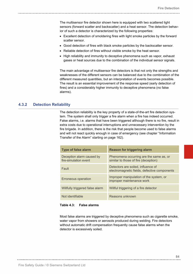
The detection reliability is the key property of a state-of-the-art fire detection sys-tem. The system shall only trigger a fire alarm when a fire has indeed occurred. False alarms, i.e. alarms that have been triggered although there is no fire, result in extra costs due to operational interruptions and unnecessary intervention by the fire brigade. In addition, there is the risk that people become used to false alarms and will not react quickly enough in case of emergency (see chapter “Information Transfer of the Alarm” starting on page 162).
Type of false alarm Reason for triggering alarm
Deception alarm caused by fire-simulation event
Phenomena occurring are the same as, or similar to those of fire (deception)
Fault Detectors are soiled, influence of electromagnetic fields, defective components
Erroneous operation Improper manipulation of the system, or improper maintenance work
Willfully triggered false alarm Willful triggering of a fire detector
Not identifiable Reasons unknown
Table 4.3: False alarms
Most false alarms are triggered by deceptive phenomena such as cigarette smoke, water vapor from showers or aerosols produced during welding. Fire detectors without automatic drift compensation frequently cause false alarms when the detector is excessively soiled.
Basically, false alarms can never be completely ruled out. However, they can be significantly reduced by taking appropriate measures: • False alarms caused by fire-simulating events can be reduced by the correct
selection and arrangement of the fire detectors (detectors with intelligent signal processing in locations with fewer deceptive phenomena).
• False alarms caused by faults can be reduced by paying attention to the quality of the products applied in selecting the system.
• False alarms caused by erroneous operation can be reduced by user-friendly control units and appropriate user training.
• Reducing willfully caused false alarms can usually be combated with additional expenditures (e.g. access control, video monitoring).
4.3.2.1 Detector Sensitivity
State-of-the-art technology makes possible the production of highly sensitive fire detectors. These detectors are capable of detecting incipient fires at an early stage. However, they are also more sensitive to deceptive phenomena. The prob-ability of deception can thus be reduced by using fire detectors with a lower sensi-tivity level – which in turn reduces the possibility of detecting fires at an early stage. The figure below shows the general correlation between detection reliability and the probability of deception.
Figure 4.15: Detection reliability and probability of deception
At the beginning of a fire, the intensity of the fire phenomena is still very low. Pos-sible deceptive phenomena at this stage may produce a signal many times higher than the signal actually wanted. To reduce the risk of false alarms, it would thus seem logical to simply give enough time to fire detection – which, however, contra-dicts the desire of early fire detection and the associated damage mitigation.
A soiled detector sooner or later causes faults or even false alarms. It may as well happen that the detector becomes less sensitive and responds too late in case of fire. Since the point-type, optical smoke detectors are by far the most frequently applied fire detectors, the aspects of detector design are explained using the example of such a detector. Soiling of detectors cannot be generally ruled out or avoided. The detector must thus be designed in a way that particle deposits inside or at the outside of the detector do not impair the detection behavior. In designing a detector, correspond-ing measures must be taken in addition to the intelligent signal processing with drift compensation. The following aspects must be taken into account: • The inlet openings must be designed in a way that the penetration of fibers, dust
and insects is aggravated, at the same time ensuring the unhindered penetration of smoke.
• The distance between the detection volume and the labyrinth must be long enough, so that fibers and other particles that have nevertheless penetrated the detector cannot reach the detection area.
• The encapsulation of the optics must be designed in a way that particles can neither settle on the emitter nor on the receiver.
In addition to soiling, especially the penetration of external light can cause faults or malfunction. This can be avoided by the design and nature of the labyrinth. To reduce malfunction due to the impact of electromagnetic fields, corresponding measures must be taken regarding the detector electronics. A sophisticated layout of mechanics, sensor unit and detector electronics is the prerequisite for reliable signal processing.
4.3.2.3 Signal Processing
By far the most effective way to improve detection reliability is the use of highly intelligent fire detection systems capable of distinguishing between deceptive phenomena and genuine fires. Apart from the high quality of sensor electronics, especially the fire detection system's intelligence plays a key role, particularly the processing and interpretation of the sensor signals. The market offers fire detection systems in which the fire detectors transmit the signals to the fire detection control unit, which is in turn responsible for signal processing. Modern fire detection systems, however, almost exclusively work on the principle of decentralized data processing. The sensor signals are directly processed in the detector, and only the evaluated results are transmitted to the control unit. The following paragraphs cover signal processing in the fire detector used in systems with decentralized data processing.
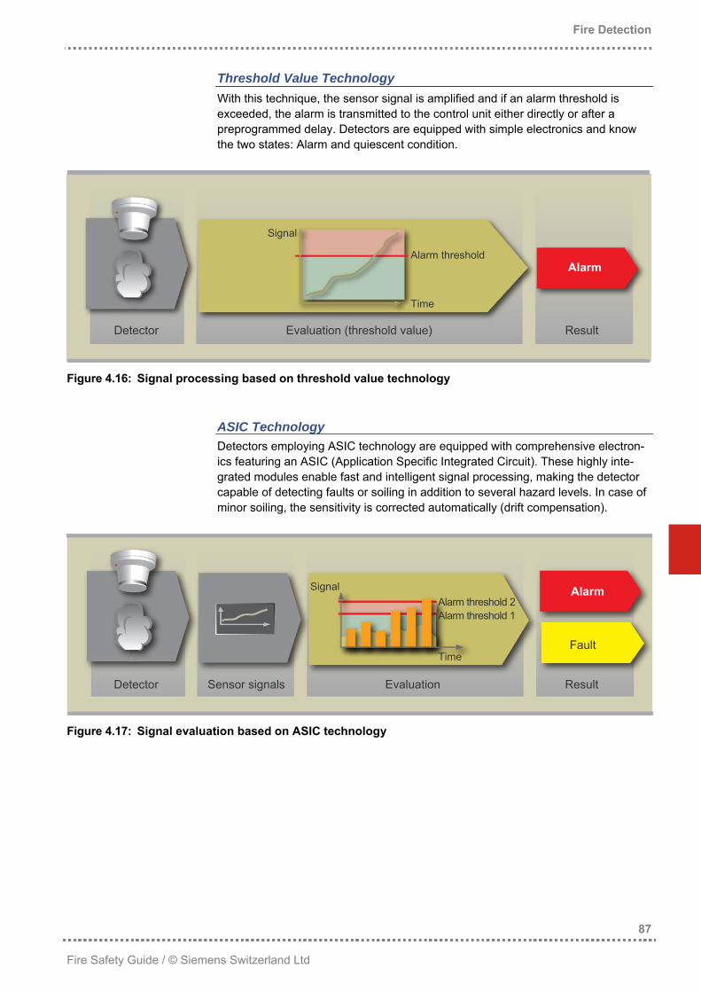
Threshold Value Technology With this technique, the sensor signal is amplified and if an alarm threshold is exceeded, the alarm is transmitted to the control unit either directly or after a preprogrammed delay. Detectors are equipped with simple electronics and know the two states: Alarm and quiescent condition.
Signal
Alarm threshold Alarm
Time
Detector Evaluation (threshold value) Result
Figure 4.16: Signal processing based on threshold value technology
ASIC Technology Detectors employing ASIC technology are equipped with comprehensive electron-ics featuring an ASIC (Application Specific Integrated Circuit). These highly inte-grated modules enable fast and intelligent signal processing, making the detector capable of detecting faults or soiling in addition to several hazard levels. In case of minor soiling, the sensitivity is corrected automatically (drift compensation).
Signal Alarm Alarm threshold 2 Alarm threshold 1
Fault Time
Detector Sensor signals Evaluation Result
Figure 4.17: Signal evaluation based on ASIC technology
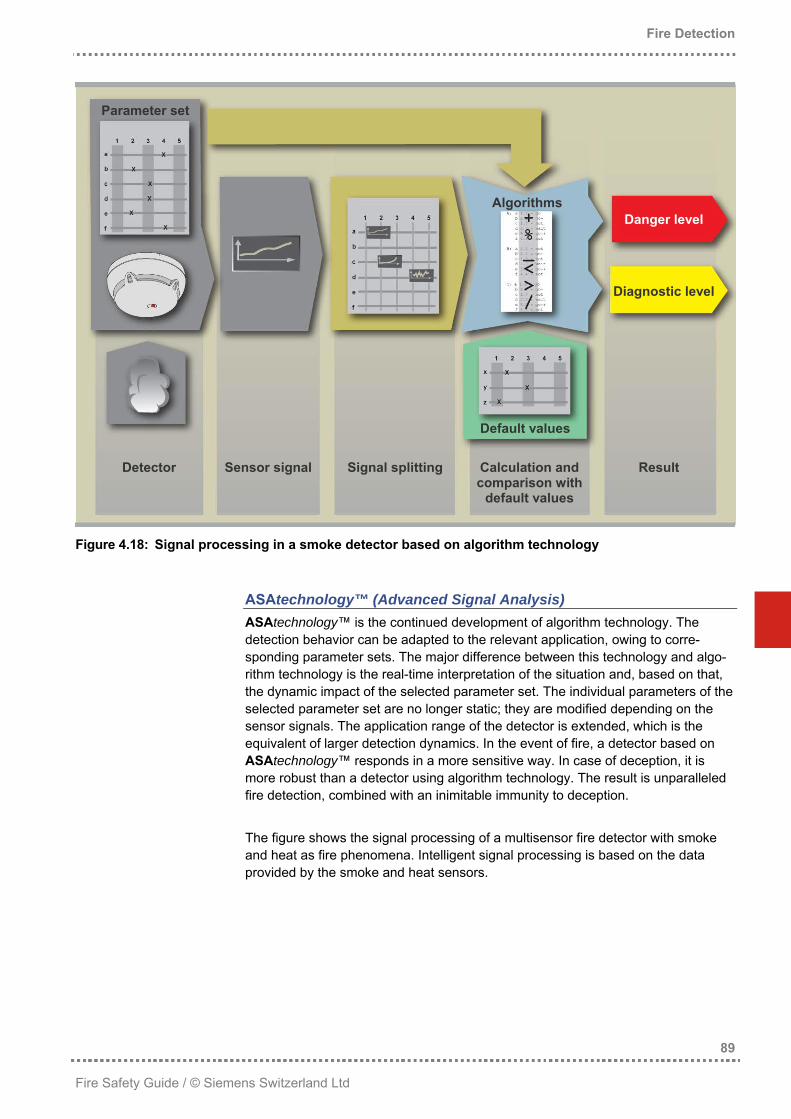
Algorithm Technology Fire detectors based on algorithm technology perform complex signal analyses at short intervals and process large data volumes. They are therefore equipped with a microprocessor. The sensor signals are broken down into mathematical compo-nents and are offset against the defined and programmed algorithms (mathemati-cal rules). The character of these algorithms is defined by their parameter setting. The comparison of the calculated values with the default values stored in the detector results in the corresponding hazard level. Fire detectors with algorithm technology do not automatically guarantee an excel-lent detection behavior, which is affected by the way the sensor signals are broken down, the mathematical rules applied, the parameter sets available and the com-parison with the default values stored in the detector. This is where knowledge comes into play. Detectors using a sophisticated algorithm technology have the following properties: • Sensor signals: Dynamic detection behavior is only possible when the signal
progression is observed and compared throughout the complete period of time the respective phenomenon is effective. Signal progression is the collectivity of the following determinants: − signal strength sensor signal (amplitude) − rate of rise change of sensor signal − fluctuation sudden changes of the sensor signal
• Mathematical rules: The mathematical rules must be set up in such a way that, in combination with the available parameter sets, they allow for all types of fire developments.
• Parameter sets: A parameter set is a set of data having an impact on the mathematical rules and on the comparisons with the default values. By loading the respective parameter set, the fixed mathematical rules are specifically set to the fire phenomena and ambient conditions to be expected, and the results are compared to the corresponding defaults. If a fire detector is installed in a produc-tion hall, a parameter set must be loaded that assesses sudden changes nor-mally caused by deceptive phenomena as relatively insignificant. If the same fire detector is installed in a hospital room, however, a parameter set must be se-lected that responds to rapid changes to the sensor signals, guaranteeing earli-est possible fire alarm. As state-of-the-art fire detectors can be operated with a wide array of parameter sets, they are suited for all types of special applications.
• Comparison with the stored default values: The stored default values are based on a large number of real fires, thus reflecting the characteristics of many different types of fire. The comparison between the calculated values and the stored default values results in the danger level (e.g. 1 = possible hazard, 2 = hazard, 3 = alarm). Additional evaluations enable statements about the detector status (e.g. soiling or fault, diagnostic level).
Detector Sensor signal Signal splitting Calculation and comparison with
default values
Result
Figure 4.18: Signal processing in a smoke detector based on algorithm technology
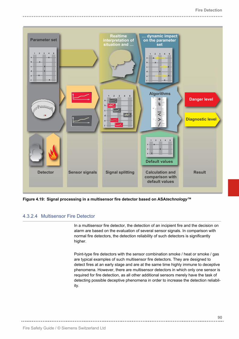
ASAtechnology™ (Advanced Signal Analysis) ASAtechnology™ is the continued development of algorithm technology. The detection behavior can be adapted to the relevant application, owing to corre-sponding parameter sets. The major difference between this technology and algo-rithm technology is the real-time interpretation of the situation and, based on that, the dynamic impact of the selected parameter set. The individual parameters of the selected parameter set are no longer static; they are modified depending on the sensor signals. The application range of the detector is extended, which is the equivalent of larger detection dynamics. In the event of fire, a detector based on ASAtechnology™ responds in a more sensitive way. In case of deception, it is more robust than a detector using algorithm technology. The result is unparalleled fire detection, combined with an inimitable immunity to deception. The figure shows the signal processing of a multisensor fire detector with smoke and heat as fire phenomena. Intelligent signal processing is based on the data provided by the smoke and heat sensors.
Detector Sensor signals Signal splitting Calculation and comparison with
default values
Result
Figure 4.19: Signal processing in a multisensor fire detector based on ASAtechnology™
4.3.2.4 Multisensor Fire Detector
In a multisensor fire detector, the detection of an incipient fire and the decision on alarm are based on the evaluation of several sensor signals. In comparison with normal fire detectors, the detection reliability of such detectors is significantly higher. Point-type fire detectors with the sensor combination smoke / heat or smoke / gas are typical examples of such multisensor fire detectors. They are designed to detect fires at an early stage and are at the same time highly immune to deceptive phenomena. However, there are multisensor detectors in which only one sensor is required for fire detection, as all other additional sensors merely have the task of detecting possible deceptive phenomena in order to increase the detection reliabil-ity.
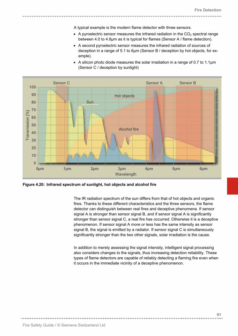
A typical example is the modern flame detector with three sensors. • A pyroelectric sensor measures the infrared radiation in the CO2 spectral range
between 4.0 to 4.8µm as it is typical for flames (Sensor A / flame detection). • A second pyroelectric sensor measures the infrared radiation of sources of
deception in a range of 5.1 to 6µm (Sensor B / deception by hot objects, for ex-ample).
• A silicon photo diode measures the solar irradiation in a range of 0.7 to 1.1µm (Sensor C / deception by sunlight)
Sensor C Sensor A Sensor B
Hot objects Sun
Tran
smis
sion
[%]
Alcohol fire
Wavelength
Figure 4.20: Infrared spectrum of sunlight, hot objects and alcohol fire
The IR radiation spectrum of the sun differs from that of hot objects and organic fires. Thanks to these different characteristics and the three sensors, the flame detector can distinguish between real fires and deceptive phenomena. If sensor signal A is stronger than sensor signal B, and if sensor signal A is significantly stronger than sensor signal C, a real fire has occurred. Otherwise it is a deceptive phenomenon. If sensor signal A more or less has the same intensity as sensor signal B, the signal is emitted by a radiator. If sensor signal C is simultaneously significantly stronger than the two other signals, solar irradiation is the cause. In addition to merely assessing the signal intensity, intelligent signal processing also considers changes to the signals, thus increasing detection reliability. These types of flame detectors are capable of reliably detecting a flaming fire even when it occurs in the immediate vicinity of a deceptive phenomenon.
Apart from the mechanical design and the sensor electronics applied, it is the signal processing that determines the quality of fire detection. Early and absolutely foolproof fire detection is the goal. When fire detectors are placed in a clean envi-ronment, this is possible without any problems today. If, however, a detector shall be able to detect a fire as early and safely as possible, even in environments where different deceptive phenomena occur, we are still faced with a challenge. Very fast fire detection combined with 100% detection reliability cannot be guaran-teed. Fire detectors with intelligent signal processing and an appropriate detector design, however, already come very close to this goal.
Figure 4.21: Detection behavior depending on signal processing
Intelligent fire detection system A
Rel
iabi
lity
of fi
re d
etec
tion
Normal fire detection system B
Fire development
Time until fire detection
Earliest possible detection combined with false alarm prevention
4.3.3 Networking Technologies
The task of a fire detector is to prevent the development of fires. There is no use in a detector that identifies a fire but does not reliably transmit the information. For this reason, fire detectors must be connected to a control unit, either hard-wired or wireless. The two most important networking methods are discussed below.
This type of networking is the oldest technology still in use today. Alarms are transmitted to the control unit by the detector lines. The control unit merely sees which line has transmitted the alarm, but not which detector. This method is thus called “collective addressing” – referring to the collectivity of all detectors on a detector line. To localize a hazard source in case of an alarm, the individual detector lines are arranged in such a way that they can be easily traced; i.e. one detector line per floor. In addition, external alarm indicators are often placed above the doors, so that the alarm triggering detector and thus the seat of fire can be found within a reasonable period of time.
4.3.3.2 Individual Addressing
Individual addressing was first introduced in the 1980s. Simpler systems still transmit their information sequentially. This means that the detectors transmit their information to the control unit one after the other, in accordance with their se-quence on the detector line. Based on this sequence, the control unit “sees” which detector has sent the information and is capable of indicating the alarm triggering detector on the display. Systems with state-of-the-art networking technology, however, make use of addressing methods known from information technology. When fire detectors with individual addressing are exclusively applied, external alarm indicators become superfluous as the alarm triggering detector is directly indicated on the fire detection control unit. Modern fire detection systems in which the signal analysis is performed in the detector itself come to a preliminary alarm decision and thus only need to transmit the corresponding alarm level. Fire detectors without built-in signal analysis how-ever depend on transmitting the measured values of the sensor signals to the control unit, which can then decide on alarm in real time.
Fires can develop explosively, fast (within a few seconds), normally (within a few minutes) or slowly (within hours). This chapter only deals with classic fire detectors used to detect fires developing from fast to slow. This document neither handles special detectors, such as pressure and spark detectors applied for explosion protection which must respond within a few milli-seconds, nor does it deal with gas sensors as they are used for the detection of smoldering fires in carbonization plant, or for the detection of combustion gases. In selecting the best suited fire detectors, the following aspects must be taken into account: − the type of fire to be expected − the room height − the ambient conditions − possibly occurring deceptive phenomena
4.4.1 Consideration of the Type of Fire
Based on their suitability, their reliability and the costs for acquisition and mainte-nance, detectors are used as follows. Detection of: − smoke: point-type and linear smoke detectors and aspirating smoke detectors. − heat: point-type and linear heat detectors. − radiation: IR and UV flame detectors. The use of point-type multisensor fire detectors that are capable of detecting both smoke and heat increases constantly.
4.4.1.1 Sensitivity of Optical Smoke Detectors
In practice, the sensitivity of optical smoke detectors is often given as a certain smoke density in %/m. This value corresponds to the detector’s response value, measured in a defined smoke channel with predefined test aerosol, defined air speed and temperature (EN54-7). This smoke density is more precisely referred to as the “light obscuration module”. The light obscuration module is calculated as follows: D = { 1 – (I/I0)1/d } x 100 [%/m] D = light obscuration module I0 = received light intensity without smoke I = received light intensity with smoke d = distance between emitter and receiver
The measurements in the smoke channel are used for testing the detectors’ stabil-ity and reproducibility and have little to do with the actual response behavior of the detectors on real fires. It is thus absolutely thinkable that a smoke detector with intelligent signal processing and a light obscuration module of 6%/m detects a real fire earlier than a detector with normal signal processing and a light obscuration module of 3%/m. The sensitivity required for approval conforming to EN 54 is checked by means of the test fires described below.
4.4.1.2 EN 54 Test Fire
The EN 54 test fires serve as proof that the detectors have sufficient sensitivity to certain fire phenomena. They are set up in such a way that each fire produces a different, typical aerosol spectrum. Such fires are mandatory to achieve approval of fire detectors. They are also quite often used for testing the response behavior of existing fire detection systems.
EN Test fire TF1 TF2 TF3 TF4 TF5 TF6
Fire type Open cellulose fire (wood)
Pyrolytic smoldering fire
(wood)
Glowing / smoldering fire
(cotton)
Open synthetic fire
(polyurethane)
Liquid fire (n-heptane)
Liquid fire (ethyl alcohol)
Heat development Strong Negligible Negligible Strong Strong Strong
Upward air flow Strong Weak Very weak Strong Strong Strong
Table 4.4: Test fires according to EN 54 and their properties
4.4.1.3 Fire Detectors and EN 54 Test Fires
EN 54 test fires are artificially induced, “ideal” fires that will rarely occur in practice, as real fires usually produce a mix of smoke types. The advantage of the EN test fires is that they produce reproducible fire phenomena and thus enable exact comparisons between the response behavior of different detectors or sensors.
Figure 4.22: Response behavior of different fire detectors on EN 54 test fires
The figure above shows the qualitative, basic capability of the detectors to respond to EN test fires. A heat detector cannot respond when a fire does not produce heat (TF 2 and TF 3). The sensor design has an additional impact on the quantitative response behavior of the sensors. The response of optical smoke detectors to TF 1, for example, depends on the scattering angle.
4.4.1.4 Selecting the Right Fire Detector
The selection of the optimum fire detector is based on the expected fire phenom-ena, generated by the incipient fire. For an office building, smoke detectors will preferably be selected, as in this case fires will produce clearly visible smoke both in the incipient phase and later. In a storage area where combustible liquids are stored, flame detectors and / or heat detectors would be the right choice. To be able to reliably detect all expected incipient fires, it may be necessary to combine different fire detector types.
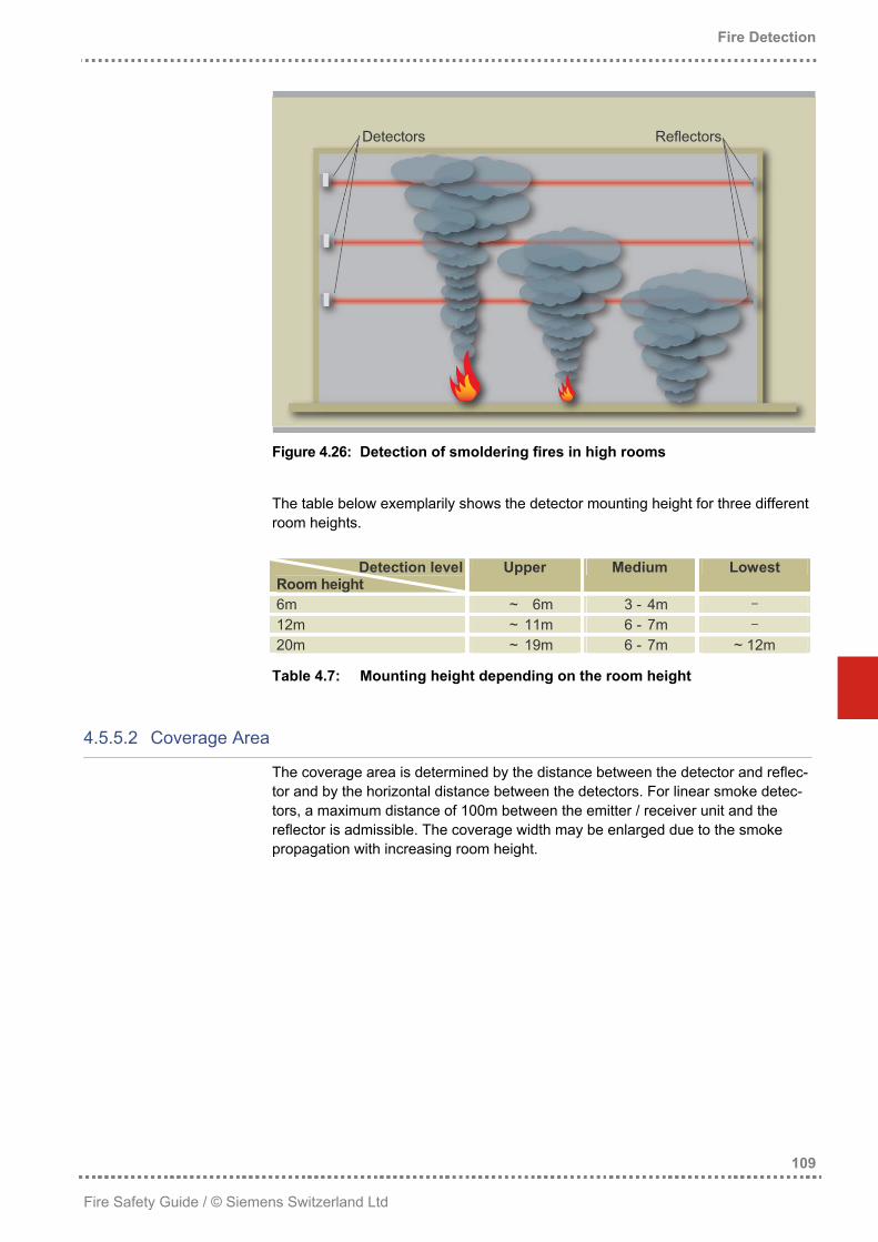
To make it possible for a fire detector to indeed detect a fire, the fire phenomenon (i.e., smoke, heat, radiation) must reach the detector. As most detectors are mounted on the ceiling, the room height limits the application range of the different detectors. The application limit for the different fire detector types is defined in the specifications. These values may vary from one country to another. Typical limits for point-type detectors are: − smoke detector max. 12.0m room height − heat detector max. 7.5m room height − flame detector max. 45.0m room height If an incipient, smoke-generating fire shall be detected in the atrium of a shopping center, the large room height neither allows for the use of point-type smoke detec-tors nor heat detectors. Flame detectors can only detect such a fire after it has developed from a smoldering to an open fire and if the fire seat is within the visible range. Depending on the room geometry, an ASD is capable of detecting an incipi-ent fire quite early, but the ideal solution in this situation is a linear smoke detector. These detectors are able to monitor distances up to 100m. They can be installed on walls at a height of 5m, for example, and can thus detect ascending aerosols which do not reach the ceiling due to the thermal conditions.
4.4.3 Considering Ambient Conditions
Fire detectors must only be applied within the temperature range specified by the manufacturer. Typical values for modern fire detectors are -25°C to +60°C. When fire detectors are applied at temperatures below zero, icing up of the detectors must be avoided, for example by installing heating elements. When heat detectors are applied, it must be ensured that the minimum response temperature is at least 10°C higher than the possible maximum ambient tempera-ture. Air movements deserve special considerations when smoke detectors shall be installed. In the event of fire, major air circulations reduce the aerosol concentra-tion, making a safe detection with normal fire detectors virtually impossible. For this reason, rooms with a high degree of air movement are preferably equipped with high-sensitive aspirating smoke detectors or with special smoke detectors installed in the ventilation duct. Fire detectors are electric devices that can be damaged by water or by the impact of solid objects. In selecting fire detectors, it must be tested whether the detector type chosen has the IP protection category required for the respective environment (see section “IP Protection Categories”, page 315).
Statistics worked out in different European countries have shown that more than 90% of all alarms triggered in fire detection systems are false alarms. A large part of these false alarms are deceptive alarms, i.e. alarms caused by external influ-ence and not by an incipient fire. Possible deceptive phenomena may be: − cigarette or cigar smoke − vapor and heat produced during cooking or in the shower − smoke produced by welding and soldering − fog generated by fog generators used for show events − exhaust gases from motor vehicles or emergency power units − dust generated during grinding or filling work − moisture condensation − heat accumulated in case of insufficient ventilation Due to their setup and the sophisticated signal processing, state-of-the-art fire detectors are largely capable of distinguishing between deceptive phenomena and genuine fires. If, however, massive deceptive phenomena are to be expected within the area to be monitored, the fire detectors’ position deserves special con-sideration, in addition to the selection of modern fire detectors with intelligent signal processing. When particular deceptive phenomena are to be expected, for example moisture condensation in the entrance area of cold storage rooms or dust in recycling facili-ties, aspirating smoke detectors are preferably installed. These systems can be equipped with appropriate additional components, such as air filters or condensate separators, so that the deceptive phenomena will not reach the detector and reli-able fire detection can be guaranteed. If deceptive alarms cannot be ruled out in spite of the optimum detector selection and position, most fire detection systems offer technical measures by which decep-tive alarms can be reduced. Among these, the most important ones are: − verification of the alarm status with intermediate alarm storage − multidetector or multizone logic
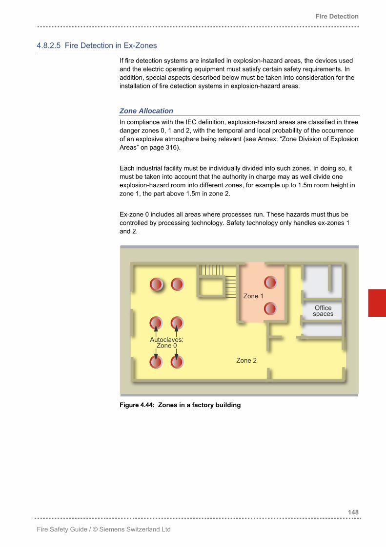
4.4.5 Fire Detectors for Explosion-Hazard Areas
Electrical operating equipment used in explosion-hazard areas must meet certain safety requirements. Fire detectors used in explosion-hazard areas must comply with a particular type of ignition protection so that they can be ruled out as potential ignition source. The term ignition protection sums up all measures taken in designing electrical operating equipment in order to prevent the ignition of an explosive atmosphere. Each type of ignition protection is advantageous for particular types of devices or applications. This is based on the principle of isolating ignition sources. The most important types of ignition protection for electrical operating equipment in explo-sion-hazard areas are described in detail in the annex “Ignition Protection Classes” on page 317.
A fire detector must be able to early and reliably detect at minimum one of the fire phenomena to be expected. Room height, environmental conditions and possible deceptive phenomena must be taken into account. The impact of deceptive phe-nomena on the detection behavior can be reduced by measures such as correct positioning, suitable detector settings or structural separation of fire sectors. In selecting the best suited fire detector, risks and costs play an important role as well. If an area with high fire risk shall be monitored, an area in which strong de-ceptive phenomena may occur and operating interruptions must be avoided at any rate, fire detection must be as early, reliable and immune to deception as possible. This is the case with automatic welding facilities, for example. In such areas, different fire detector types are often combined, for example multisensor fire detec-tors and flame detectors. In an office building with smoking ban, the use of smoke detectors will completely suffice. For use in dirty environments or explosion-hazard areas, fire detectors must meet special requirements set up for the respective area. The following paragraphs describe some typical application areas for the different types of fire detectors.
Point-type Smoke Detectors Point-type smoke detectors are used in areas where incipient, smoke-generating fires are to be expected and where little or no deceptive phenomena occur. As it has already been described in section 4.3.1.1, scattered light smoke detectors are particularly suited to detect light smoke particles, whereas the strength of ionization smoke detectors lies in the detection of small, dark smoke particles. As a radioac-tive radiation source is used, and due to the resulting disposal problems, ionization detectors are used less and less frequently. Typical application areas for point-type smoke detectors are: − rooms where smoking is prohibited such as
− hospitals − nursing homes − offices
− museums and exhibition rooms − storage halls for paper, consumer electronics, etc. − production facilities for electronic products − EDP rooms (in combination with an ASD system) − communication facilities
Point-type Heat Detectors Point-type heat detectors are used in areas where incipient fires generate much heat. Heat detectors should principally be used only in areas where process-related deceptive phenomena such as intensive aerosol concentrations render the use of other detector types impossible.
Typical application areas for point-type heat detectors are: − canteen kitchens with low ceilings − interlocks in cooling facilities, where fog is produced by condensation − storage halls for combustible liquids generating little smoke in case of fire
(mostly in combination with flame detectors)
Point-type Multisensor Detectors The use of point-type multisensor fire detectors that simultaneously detect smoke and heat is increasing steadily. Due to the intelligent interlinking of the sensor signals, such detectors are characterized by early and highly reliable fire detection. They are thus applied in all areas where early detection and high resistance to deception are of equal importance. Typical application areas for point-type multisensor fire detectors are: − offices, conference rooms, hotel rooms, restaurants, etc., where smoking is
allowed − rooms with kitchenettes in nursing homes − production halls where deceptive phenomena may occur − parking facilities for motor vehicles or Diesel locomotives − all types of storage buildings (food and animal feed industries, cooling facilities) − canteen kitchens with ceilings higher than 3m − discotheques and other event centers in which artificial aerosols may be re-
leased
Linear Smoke Detectors Linear smoke detectors are used in areas in which smoke-generating incipient fires are to be expected and where point-type smoke detectors cannot be used. Typical application areas for linear smoke detectors are: − very high rooms (atriums, hangars) − large halls in which the maintenance of point-type detectors would be more
difficult or more expensive than that of linear smoke detectors − areas with strong operational danger of soiling of point-type detectors (sawmills,
spinning works) − historical buildings in which point detectors are unwanted for esthetical reasons
Aspirating Smoke Detectors Aspirating smoke detectors are used wherever smoke-generating fires must be detected as early as possible and point-type detectors are too insensitive or not sufficiently robust against soiling. Typical application areas for aspirating smoke detectors are: − rooms with a high concentration of valuable property where even smallest aero-
sol concentrations must be detected (EDP rooms, chip production facilities) − very high rooms where the smoke concentration below the ceiling is strongly
diluted due to the large volume (atriums, hangars) − large halls in which the maintenance of point-type detectors would be more
difficult, or where point-type detectors would be essentially more expensive than aspirating smoke detectors
− areas where point-type detectors are prone to operational soiling (recycling facilities, heavy-duty industry)
− rooms where strong deceptive phenomena such as moisture condensation are to be expected (entrance areas of cooling facilities)
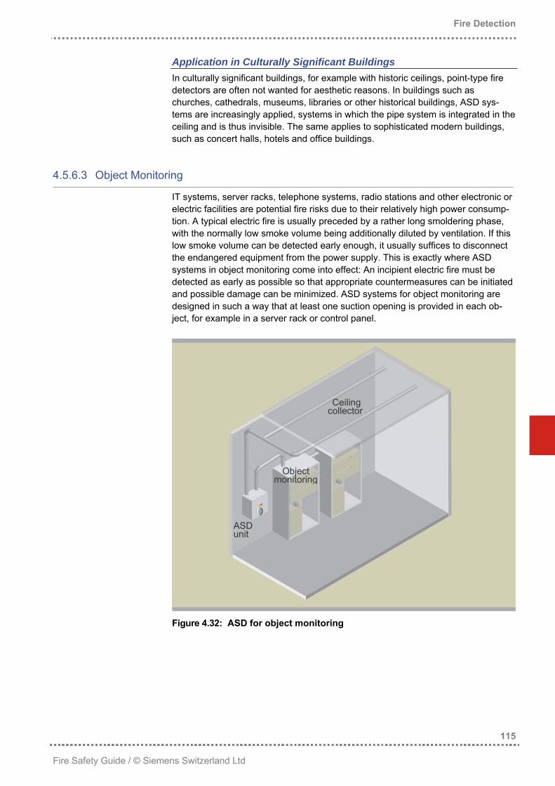
− historical buildings in which point detectors are unwanted for esthetical reasons − areas with increased danger of vandalism (e.g. in prisons)
Flame Detectors Flame detectors are used in areas where open fires may occur very rapidly and where large open areas must be monitored. Typical application areas for flame detectors are: − storage facilities for combustible liquids − open storage halls or loading decks − oil and fuel tank farms − paint shops − motor test stands − recycling facilities
Example: Workshop The following example shows some considerations on the selection of the optimum fire detector in a workshop. A workshop with a room height of 7m shall be monitored with fire detectors. Weld-ing work is frequently performed in this workshop. In addition, there are Diesel-driven forklift trucks. These deceptive phenomena might cause false alarms with smoke detectors. The use of heat detectors shall thus be discussed to reduce or avoid the risk of deceptive alarms. The following prerequisites apply for heat detectors: • In many countries, a category 1 heat detector with a response temperature of
62°C may be applied up to a maximum room height of 7.5m. The maximum ad-missible monitoring area is 20m2.
• Calculations show that such a heat detector is able to detect a wood fire of 0.5m2 with a power of approx. 110kW and a flame height of approx. 1.2m. These details are correct when the fire occurs directly underneath the detector and when there is no air circulation. Assuming that the fire would occur a few meters beside the detector and there would be slight air movements in the room, such a detector sees a fire only when it produces several hundred kW of heat.
For an objective-oriented protection setup of a fire detection system, it must thus be clarified whether the protection objective allows for such a fire. Otherwise, a different solution for an earlier detection of a possible fire must be found. Examples are: − smoke detectors with high immunity to deceptive phenomena − smoke detectors with multidetector zones, with the alarm only being transmitted
when a predefined number of detectors (usually 2) are in alarm status − flame detectors
This example shows how complex the selection of the optimum fire detector can be. In practice, of course, not each and every single fire detector can be planned in this way, which is why highly experienced specialists are required to set up a fire detection system. Selecting the best suited detector type requires both profound technical knowledge and a grasp for the application itself, its risk, the combustible load, the possible fire progression and the probable and achievable fire size.
In some cases, fire detection systems must be set up for objects in which one cannot accurately predict how a fire will develop or the smoke will spread. In such cases, the selection of the detector types, their settings and positioning must be found out by means of simulation tools or optimized on site.
Development Taking a closer look at automatic fire detectors applied today, more than 90% are point-type fire detectors. Of these, approximately 75% are smoke detectors, 5% are heat detectors and 20% are multisensor fire detectors. In many applications, a clear shift from the “pure” smoke or heat detector to a multisensor fire detector can be observed. The reason is that multisensor fire detectors make a more reliable and nevertheless early detection of many different fire types possible. In addition, the price difference to conventional, point-type smoke detectors has decreased significantly over the past years. For special applications, ASD systems are applied increasingly, as they can detect fires at a very early stage and may as well be applied in rooms with strong deceptive phenomena, provided that additional meas-ures are taken.
Selecting the optimum fire detector requires both knowledge and experience
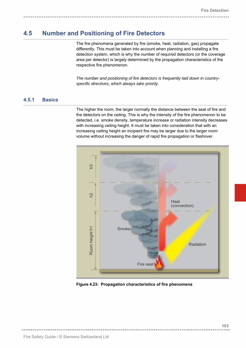
The fire phenomena generated by fire (smoke, heat, radiation, gas) propagate differently. This must be taken into account when planning and installing a fire detection system, which is why the number of required detectors (or the coverage area per detector) is largely determined by the propagation characteristics of the respective fire phenomenon. The number and positioning of fire detectors is frequently laid down in country-specific directives, which always take priority.
4.5.1 Basics
The higher the room, the larger normally the distance between the seat of fire and the detectors on the ceiling. This is why the intensity of the fire phenomenon to be detected, i.e. smoke density, temperature increase or radiation intensity decreases with increasing ceiling height. It must be taken into consideration that with an increasing ceiling height an incipient fire may be larger due to the larger room volume without increasing the danger of rapid fire propagation or flashover.
Figure 4.23: Propagation characteristics of fire phenomena
Smoke The thermal characteristics of open fires transport the smoke particles, which become diluted in the larger air volume, even to very high ceilings. This smoke dilution must be accommodated by the use of smoke detectors with sensitive response behavior. Smoldering fires largely lack the thermal conditions to transport smoke. Such fires are thus only recognized by detectors mounted on high ceilings after they have developed to open fires.
Heat The warm air ascending from the fire cools down with increasing distance, which means that heat detectors are of limited use with increasing room heights.
Radiation Although the radiation energy is reduced the larger the distance between fire seat and detector, flame detectors can be used in very high rooms thanks to their high response sensitivity.
Generally Applicable Facts In arranging the fire detectors, it must be ensured that the fire phenomena reach the fire detectors, so that the detector can indeed recognize a fire. Each room to be monitored must be equipped with at least one automatic fire detector. Fire detectors must be principally arranged symmetrically and evenly throughout the room. The detector placement must comply with the prevailing room conditions (e.g. the ceiling’s construction: ceiling with girders, special roof or ceiling shapes) or room divisions (alcoves, furniture, equipment, etc.). Additional considerations in placing fire detectors include: • In some countries, flame detectors may be applied up to room heights of 45m. It
must be clarified, however, which fire size may still be detected with such an ar-rangement, and whether the defined protection objective can still be achieved.
• When monitoring a room where very strong deceptive phenomena may occur, the optimum arrangement of the fire detectors is crucial. Minor changes to the detector position may lead to massive improvements relating to the immunity to deception without impairing the detection reliability.
• In very special cases, experience alone does not suffice – tests on site become necessary to determine the optimum detector position.
Manual call points must be placed at a clearly visible location along escape routes, for example in corridors, staircases, entrance halls, besides extinguishing posts and in especially endangered areas at a distance of maximum 40m.
Figure 4.24: Positioning of manual call points along escape routes
Manual call points must be generally installed at a height of 1.5 to 1.7m above the floor, in order to avoid erroneous operation, for example by mistaking them for light switches in the dark).
4.5.3 Point-type Smoke Detectors
Point-type smoke detectors are installed either on the ceiling or where the strong-est propagation and accumulation of smoke is expected. Point-type multisensor fire detectors, which simultaneously detect smoke and heat, must be arranged in the same way as point-type smoke detectors.
4.5.3.1 Impact of the Room Height
Point-type smoke detectors may normally be installed at a room height up to 12 meters. With increasing room height, the smoke density on the ceiling decreases, as the total smoke volume spreads throughout a larger air volume. In addition, smoke cooling off can no longer break through the heat cushion accumulating on the ceiling of high rooms.
This results in the conclusion that at increasing room height: − the response sensitivity of the fire detection system must be higher, or an in-
creasingly larger incipient fire is required to trigger alarm − the coverage area per smoke detector may be larger − smoke from smoldering fires will hardly reach the ceiling and thus the detectors − the smoke detectors must be placed at larger distances from the ceiling These physical conditions must be taken into account in selecting the response sensitivity and determining the distance to the ceiling.
The coverage area is defined depending on the room height and the fire risk.
Figure 4.25: Coverage area per smoke detector depending on the room
height and the hazard potential
Area 1 with minor hazard potential should only be selected when the following conditions are fulfilled:
Room height
2 13 Coverage area per smoke detector
− any danger to human life can be ruled out − neither valuable property nor irreplaceable goods are stored in the area − the fire risk is very low − other fire protecting measures prevent possible fire propagation − no hazard can be caused in adjacent areas, for example by corrosive decompo-
Area 2 with medium hazard potential can be selected for most applications. Area 3 with high hazard potential is recommended in the following cases: − increased danger to life − valuable property or irreplaceable goods are stored in the area − the loss of goods or installations could endanger the economic existence of the
owner − the fire risk is classified as “high” In artificially ventilated rooms, natural smoke propagation is impaired. The higher the air movements, the more the smoke particles are discharged without the possi-bility of a uniform smoke concentration building up. This reduced and locally differ-ent smoke distribution leads to a delayed response of the fire detection system, which may partially be compensated by reducing the coverage area and increasing the detector sensitivity.
4.5.4 Point-type Heat Detectors
In contrast to smoke detectors, heat detectors must always be installed at the highest point on the ceiling. To avoid false alarms and at the same time guarantee-ing an acceptable response behavior, the static response temperature of heat detectors must be between 10°C and 35°C higher than the highest temperature that can occur by natural or operational developments in the immediate vicinity of the detector.
4.5.4.1 Impact of the Room Height
Heat detectors of class A1 may normally be installed at room heights up to 7.5m. The temperature at the ceiling, directly above the fire seat, decreases by the power of two with increasing room height. This means that the response sensitivity of the detectors must be set higher with increasing room heights, or else, that a larger fire would be necessary to trigger alarm.
4.5.4.2 Coverage Area
The coverage area depends on the size of the room to be monitored and on the inclination of the ceiling. With inclined ceilings, the heat ascends along the ceiling inclination and up to the highest point, resulting in heat concentration in the ridge. For this reason, both the basic coverage area and the detector distances may be increased with inclined roofs. The maximum admissible distance between detec-tors (s), or between a detector and the wall (½s) depends on the coverage area and the roof inclination.
Maximum coverage area (AM) and maximum distance between detectors (s)
Roof inclination (angle α) < 10° 10° - 20° > 20°
Basic surface area of the room to be monitored AM s AM s AM s
≤ 30m2 30m2 7.8m 30m2 9.2m 30m2 10.6m
> 30m2 30m2 6.6m 30m2 9.2m 40m2 12.0m
Table 4.6: Coverage areas and distances between heat detectors
The distances between detectors and walls, equipment or stored goods must not fall below 0.5m, with the exception of corridors, channels, ducts or similar construc-tions with a width below 1m. If there are any girders, beams, etc., or air condition-ing ducts closer than 0.15m under the roof, the lateral distance of at least 0.5m must be considered as well.
4.5.5 Linear Smoke Detectors
Direct and unhampered visibility between the detector and the reflector must be ensured. The monitoring ray must not be interrupted by moving objects such as overhead cranes, ladders, etc. The detector must be secured in a way that it is fixed and inflexible. It must be taken into account that flexible wall constructions are unsuited, as a too large deviation of the monitoring ray makes reliable detection virtually impossible. Con-crete and brick walls meet these prerequisites, whereas wood or steel construc-tions are mostly unsuited, as they may be affected by temperature or moisture changes, wind or snow pressure.
4.5.5.1 Impact of the Room Height
Heat cushions below the ceiling can prevent ascending smoke from reaching the ceiling. Linear smoke detectors must thus be installed below a heat cushion to be expected (see Table 4.5 on page 106). With room heights above 12m, the distance to the ceiling should be 60 to 120cm. To make sure that smoldering fires or smaller fires with low fire thermals can be detected in high rooms, a second and possibly third detector must be installed at the assumed level of the smoke propagation of a smoldering fire. This differentia-tion in levels becomes important in rooms higher than 6m.
Figure 4.26: Detection of smoldering fires in high rooms
The table below exemplarily shows the detector mounting height for three different room heights.
Detectors Reflectors
Detection levelRoom height
Upper Medium Lowest
6m ~ 6m 3 - 4m –
12m ~ 11m 6 - 7m –
20m ~ 19m 6 - 7m ~ 12m
Table 4.7: Mounting height depending on the room height
4.5.5.2 Coverage Area
The coverage area is determined by the distance between the detector and reflec-tor and by the horizontal distance between the detectors. For linear smoke detec-tors, a maximum distance of 100m between the emitter / receiver unit and the reflector is admissible. The coverage width may be enlarged due to the smoke propagation with increasing room height.
Figure 4.27: Monitoring width depending on the room height
The values given here apply for rooms with a low fire risk. To cover larger risks, the monitoring width should be half the value shown above.
Roomheight
Maximum monitoring width
4.5.6 Aspirating Smoke Detectors
ASD systems are applied for room monitoring (storage rooms, cooling facilities, hangars, etc.) and for object monitoring (control panels, IT and telephone facilities, radio stations, etc.).
4.5.6.1 Sensitivity
If a fire occurs in a room, the smoke ascending due to the thermal conditions is gathered by the suction openings and is guided to the smoke detector via the pipe system. The ASD triggers an alarm as soon as the average smoke concentration of all suction openings exceeds the alarm threshold. It does not matter whether this value is caused by very high smoke concentration at one suction opening or by a slightly higher smoke concentration at several suction openings. The required ASD sensitivity can be calculated by means of the following formula: S
SASD = required sensitivity of the ASD sensor SDP = sensitivity at the point of suction as required by the fire protection con-
cept NDP = selected number of suction points in the pipe system NDPS = accepted smoke propagation (number of suction points in the smoke)
As a general rule, ASD systems are classified in the following sensitivity catego-ries: − normal sensitivity with a smoke sensitivity of 1.0 to 0.1%/m − high / highest sensitivity with a smoke sensitivity of 0.1 to 0.005%/m If a fire shall be detected as early as possible, the ASD system must trigger an alarm as soon as there is smoke at one suction point. Such systems usually re-quire a very high ASD sensitivity. In room monitoring, an alarm is often accepted even if the smoke propagation is already so advanced that the smoke is aspirated by more than one suction point. If smoke reaches two or three suction points, twice or three times as much smoke is detected by the ASD. This is called accumulative effect or smoke accumulation. If an alarm is also accepted when larger smoke propagation has already taken place, an ASD system with lower sensitivity can be chosen.
Example: Recycling Hall An ASD system shall be installed in a recycling hall to detect medium-sized fires. The following preconditions are specified: • The response behavior shall be similar to a system with point-type smoke detec-
tors (sensitivity at the suction point: 3%/m). • The monitoring area of 800m2 shall be covered by a pipe network with 10 suc-
tion points. • Alarm shall be triggered when the smoke on the ceiling reaches 3 suction points. By applying the above formula, the required ASD sensitivity is calculated as (3/10) x 3 = 0.9%/m.
Figure 4.28: Detection with accumulative effect in a hall
With normal room monitoring, the pipe system and the suction points are selected in a way that each suction point has a coverage area of 40 to 80m2, which is com-parable to point-type smoke detectors. The pipe system is mounted below the ceiling. In false floors and suspended ceiling with a corresponding combustible load, the pipe system is mounted in such a way that the suction points are at the highest possible point. Due to the large air volume, strong smoke dilution can be observed in large high rooms such as storage rooms, atriums or hangars. If a fire in such a room shall be detected at an early stage, a correspondingly sensitive system must be chosen. In addition, in high rooms, heat cushions often occur below ceilings, caused by strong solar radiation or by air warming due to fire. Such heat cushions partially or com-pletely avoid that the smoke reaches the ceiling. This must be taken into account in placing the ASD suction pipes (see Table 4.5 on page 106).
Figure 4.29: Pipe system below an inclined roof
In high storage rooms, the suction pipes are preferably mounted vertically. This way, the heat cushion effect can be largely neutralized and, in addition, smaller fires in the storage racks can be detected early thanks to this arrangement.
ApplicatioIn addition toto soiling in optical systein such a wathe pipe syspenetrate thare additionaantees a reli
ApplicatioAir conditionwhich in turnwith fresh aiuse ASD sysfeed a sampexhaust air ioutlet openin
A
SD unit
113
d Ltd
Pipe system in a high-rack storage building
ing ASD systems in special areas, additional points briefly mentioned be taken into consideration.
n in Strongly Soiled Environments maintaining a reliable detection, ASD systems must also be resistant
rough environments. Smallest particles are deceptive elements for ms, leading to false alarms or, in the worst case, impairing the system y that it can no longer work reliably. For this reason, filters are built in tem in rough environments, filtering dirt particles before they can e measuring system. In strongly soiled environments, the suction pipes lly purged periodically to clean them from dirt or deposits. This guar-
able transport of the aspirated air to the measuring system.
n in Areas with High Air Circulation ing equipment or air recycling systems can cause high air circulation, sometimes produces essential smoke dilution, as the smoke is mixed
r before it reaches the detectors. In such conditions, it makes sense to tems with increased or very high sensitivity. It also makes sense to le of exhaust air to the ASD, in addition to the “pure” ambient air. The s monitored directly before reaching the room ventilation system’s g.
Figure 4.31: Pipe system with high air circulation
Application in Humid Environments In humid environments, water traps with sluice valves are installed in the suction pipe.
Application in Refrigerating Warehouses Due to the very dry air and the highly combustible isolating and packaging material, refrigerating warehouses constitute a high fire risk. A fire in such a facility may propagate quickly and cause a lot of damage, therefore early detection of a spreading fire is of utmost importance in this case. In refrigerating warehouses, ASD with high sensitivity are normally used. To prevent frost formation on the suction openings, the pipe systems are provided with a blow-out mechanism. This is of special importance in the entrance area where high relative air humidity pre-vails due to the air circulation, resulting in a high tendency of frost formation.
Application in Areas Prone to Vandalism In areas prone to vandalism, the suction pipe is mounted in the ceiling. Only very small, almost invisible holes are present in the monitoring area. This type of instal-lation can often be found in penal institutions.
Application in Culturally Significant Buildings In culturally significant buildings, for example with historic ceilings, point-type fire detectors are often not wanted for aesthetic reasons. In buildings such as churches, cathedrals, museums, libraries or other historical buildings, ASD sys-tems are increasingly applied, systems in which the pipe system is integrated in the ceiling and is thus invisible. The same applies to sophisticated modern buildings, such as concert halls, hotels and office buildings.
4.5.6.3 Object Monitoring
IT systems, server racks, telephone systems, radio stations and other electronic or electric facilities are potential fire risks due to their relatively high power consump-tion. A typical electric fire is usually preceded by a rather long smoldering phase, with the normally low smoke volume being additionally diluted by ventilation. If this low smoke volume can be detected early enough, it usually suffices to disconnect the endangered equipment from the power supply. This is exactly where ASD systems in object monitoring come into effect: An incipient electric fire must be detected as early as possible so that appropriate countermeasures can be initiated and possible damage can be minimized. ASD systems for object monitoring are designed in such a way that at least one suction opening is provided in each ob-ject, for example in a server rack or control panel.
The electromagnetic radiation of possible fires must reach the flame detector. Within the range of sight, this is ensured by direct irradiation. If the direct view is blocked, IR flame detectors can still detect due to the reflection on the metal sur-faces. UV flame detectors, however, are powerless in such cases, as UV is not, or only rarely, reflected. It must be taken into account that direct infrared radiation is always many times stronger than indirect infrared radiation. Flame detectors should thus always be installed within sight of the entire monitoring area and are thus preferably placed in a high corner of the room.
Figure 4.33: Flame detectors with direct and indirect visibility
When placing the flame detectors, equipment or obstacles such as wings must be taken into consideration. In a hangar, the area underneath the wings must be monitored by flame detectors as well.
Figure 4.34: Positioning flame detectors in a hangar
If several flame detectors are required in one room, they should be arranged so that there is a high redundancy, that is, the monitoring areas of the individual flame detectors should overlap.
Figure 4.35: Arranging flame detectors in large rooms
4.5.7.1 Detection Distance
Of essentially greater significance than the maximum admissible room height is the detection distance in the project planning of flame detectors. The detection dis-tance is the distance between the detector and the farthest point that still needs to be monitored. The response sensitivity decreases approximately to the second power with increasing distance. From this, it follows that the response sensitivity of the flame detector must be significantly higher or that a larger, open fire is neces-sary to trigger alarm. This is clarified by the following examples: • If the distance from the flame detector to the fire is 20m. For example, a flame
detector is capable of detecting a fuel fire with a surface area of 0.025m2, a flame height of 0.6m and 18kW power.
• If the distance from the flame detector to the fire is 70m, a fuel fire with a surface area of 0.25m2, a flame height of 2.2m and 400kW power is required to ensure the detector triggers alarm.
4.5.7.2 Monitoring Area
Based on the maximum size of the fire to be detected and the response sensitivity of the detector, the maximum detection distance (d) is determined. As flame detec-tors with an angle of visibility of 90° are usually installed at an inclination angle of 45°, the maximum detection distance (d) of the room diagonal corresponds to a cube. As this is by √3 longer than the side (a) of the cube, the maximum fixation height is a = d/√3. This results in a monitoring area of a2 = ⅓d2.
Depending on the ratio of room surface and room height, it might make sense to choose an inclination angle smaller than 45°. If, however, an angle > 45° is cho-sen, the area directly underneath the detector with a visibility angle of 90° is no longer within the visible range and thus not monitored.
4.6 Fire Detection Control Unit and Peripheral System
The fire detection control unit evaluates the signals transmitted by the peripheral devices, it controls the fire alarm and control installations and is also the point of interaction between the operator and the system. The term “peripheral system” summarizes the networking of the fire detection control unit with the peripheral devices, such as fire detectors, alarm devices and fire control installations. Commissioning reveals how easily and flexibly a fire detection control unit can be parameterized according to customer needs. Some of these aspects should al-ready be taken into account when evaluating the fire detection system.
Control interfaceLine
interface
Fire detection control unit
Commissioning Maintenance
Figure 4.37: Fire detection control unit and peripheral system
The fire detection control unit is the core element of each fire detection system. Compact and medium-sized systems usually have only one control unit, whereas more complex systems often consist of several networked control units. This makes it possible to act upon all control units by one single procedure. In such a system, sensors and actuators can ideally be allocated to different control units, and control can be performed so that it acts on several control units. In addition, the transmission of fire alarms and faults to the receiving equipment can be ef-fected centrally by a main control unit integrated into the network. This essentially reduces the connection fees and dedicated line fees. How comprehensive the functionality is in the specific case must be clarified in advance for each individual system.
4.6.1.1 Setup
Each fire detection control unit comprises a minimum of five components: • Main processor: The main processor is the heart of every fire detection control
unit. It coordinates and controls the entire fire detection system. • Operating panel: This panel consists of indicating, acoustic and operating
elements. The indicating and acoustic elements inform the operator on the sys-tem status (alarm, fault, operating mode, etc.). The operating elements make it possible to operate the system by acknowledging messages, or switching from unmanned to manned mode.
• Line interface: The line interface communicates with the peripherals and transmits information to the main processor.
• Control interface: The control interface transmits the information received (e.g. fire door open) to the main processor and activates the control outputs required by the main processor (alarm devices, fire control installations, etc.).
• Power supply: The power supply unit provides the energy required for the fire detection system.
Depending on the requirements and size of the fire detection system, the setup of the fire detection control unit can largely vary. For a small hotel with 30 rooms, for example, a control unit will suffice in which the main processor, operating unit, line interface and control interface are combined on one board. Complex systems are equipped with several line and control plug-in units. With such systems, remote operation and the possibility to operate the system from different locations is fre-quently required. Such operating terminals are connected to the control unit via a control unit bus designed in compliance with the highest safety standards. Alternatively, there is the possibility of visualizing the control unit’s user interface by a mere software solution on a PC. The connection to the PC can be established by a LAN, for example (see Glossary, starting on page 297). This solution also makes it possible to indicate and operate several networked control units on the monitor of a danger management system (see chapters 7.2ff starting on page 240).
In compliance with EN 54, two independent energy sources must guarantee the power supply to the fire detection control unit. Both energy sources must be sized such that in case of failure of one source, the operation of the system and the alarm equipment can be maintained for a predefined period of time. The following aspects must be taken into account: • One of the two energy sources must be a permanent mains supply, the second
one a battery or equivalent. • Parallel operation is mandatory, with the appropriately sized charging unit feed-
ing the fire detection system and at the same time charging the batteries con-nected in parallel.
• The mains power supply of the fire detection system must be effected via a separate, safe supply line.
• Devices that do not constitute part of the fire detection system must not be connected to the system’s power supply!
• The battery’s capacity must be such that unimpaired operation of the fire detec-tion system is possible during the required emergency operating time and that the alarm devices can still be fed for a minimum of 30 minutes after the emer-gency operating time has expired.
• The use of satellite power supply units is admissible. However, they must be monitored for permanent operability.
• Messages received from the satellite power supply units must be indicated on the control unit, just like fault signals.
Regarding the detection of fault signals and troubleshooting, the following emer-gency operating times are recommended: Emergency operating criteria Duration Without fault signal transmission 72 hours
With fault signal transmission, unmonitored line 24 hours
With fault signal transmission, but with permanently manned signal receiving center at the installation location
12 hours
With fault signal and monitored line 12 hours
Secured mains connection (e.g. emergency power Diesel generator for 24h operation) and fault signal transmission
4 hours
Table 4.8: Emergency operating times as required by EN 54
A state-of-the-art fire detection control unit must feature the following: • Easy and safe system operation. • Free adaptation of the control unit organization to changing customer require-
ments. • Free programmable control outputs to use fire control installations. • Manufacturer-specific battery charging characteristics and periodic endurance
testing of the batteries, in order to achieve optimum charging conditions and a longer service life of the emergency power batteries.
• Real-time clock with date and automatic summer- / wintertime changeover. • Event memory storing hundreds of events, sorted by information category, and
making them available on demand. • Integrated emergency operating functions so that safe fire detection can still be
ensured in case of failure to a signal processing unit.
4.6.1.4 Operation
The user interface of a fire detection control unit must be set up so that the basic functions such as alarm or reset alarm are easy to understand and to operate. This makes sure that such operations can also be performed by persons who rarely have to work on the system or who have received only elementary instructions. Such a man-machine interface places high demands on an ergonomic arrange-ment of the operating elements, on the representation of messages and on a user-friendly operating structure. This is why state-of-the-art fire detection control units are provided with so-called “soft keys“ – function keys for the display of context-related commands used with the respective application. In case of fire, for example, the location of the fire is indicated, and on the operating elements only functions such as ”Acknowledging the alarm” or ”Resetting the alarm” are released and the corresponding countermeasures texts are displayed. Operation of a fire detection control unit not only comprises alarm processing. Functions such as processing faults, switching from manned to unmanned, or switching off detectors are other functions of a fire detection control unit. Since functions like switching off detectors can impair safety, they must only be per-formed by authorized and accordingly trained staff. State-of-the-art fire detection control units thus offer the possibility of releasing commands in the menu structure for some authorization levels only. The table below shows an example with 4 authorization levels.
- Switching off acoustic elements on the operating panel
- Switching to manned / unmanned
Competent person, e.g. janitor
2 - Commands from authorization level 1
- Resetting alarms - Switching off detectors
Trained person, e.g. company electrician
3 Switching detectors into revision mode, commands from authorization levels 1 and 2
Electrician or expert for danger management systems, e.g. maintenance engineer
4 Opening the fire detection control unit, exchanging modules, changing the system parameter settings, commands from authorization levels 1, 2 and 3
Electrician or expert for danger management systems, e.g. maintenance engineer acknowledged as installer
Table 4.9: Authorization levels for a fire detection control unit
4.6.1.5 Location
For the fire detection control unit, a location close to the main entrance or the fire brigade access of the building to be monitored should be chosen. This location must be agreed upon in advance with the organization (e.g. fire brigade) accepting the fire detection control unit. It often suffices to place the fire department control panel in the fire brigade’s main access, as in this case the fire detection control unit can be placed in any room easily accessible for the wiring arrangement. In larger building complexes where networked fire detection control units are used, they are often installed in decentral locations, so that the lines to the detectors and other peripheral devices can be kept as short as possible. To keep influencing factors which might lead to false alarms or faults as low as possible, only locations free from high electromagnetic interference (EMI) may be selected for the fire detection control unit.
4.6.2 Peripheral System
Devices that are not an integral part of the fire detection control unit are allocated to the peripheral system. In addition to the connected detector lines and the com-ponents on these lines, the peripheral system includes the complete supply net-work with alarm devices, fire detection control installations and fire department control panels.
With fire detection systems, the safety and reliability topic deserves top priority. This applies especially to selecting and installing the supply networks to the fire detectors, alarm devices, fire control installations, etc. When selecting and install-ing, the following aspects must be taken into account: • The peripheral devices must be operated via a separate supply network. • Although state-of-the-art detector systems are highly immune to electromagnetic
interference, the detector lines should be separated from other lines and sys-tems.
• To minimize electromagnetic interference acting on the system, always use twisted pair cables with new installations.
4.6.2.2 Detector Line
The detector line links the peripheral devices to the fire detection control unit. Over the last decades, information technology has led to major changes that are still relevant for essential differences between system types in use today.
Topologies The peripheral devices or line components of a fire detection system are con-nected to the fire detection control unit via a stub or loop line. Additionally, modern fire detection systems make it possible to use T-tabs without additional elements, which increases the flexibility in wiring arrangement, at the same time reducing system costs.
Figure 4.38: Fire detection control unit with different detector lines
For reasons of safety, stub lines today are only used in systems where fire detec-tors with conventional technology are applied or where existing lines are reused. Individually addressed elements on a loop line ensure a considerably higher fail safety of peripheral devices. In case of an open line, all elements remain fully operable, as the control unit may communicate with the elements from both sides of the loop. When all connected elements (fire detectors, input / output modules, alarm elements) use a separator function, the entire system remains fully operable even in case of a short-circuit, as the short-wired line segment is decoupled by the separators. Otherwise, at least every 32nd element must be equipped with a separator conforming to EN 54.
Collective Connection With a collective connection, all detectors with conventional technology are con-nected in parallel to the same stub line (see section 4.3.3.1 on page 93). To indi-cate an alarm or a fault, a detector increases its power consumption. This change is evaluated correspondingly in the control unit. With a collective connection, the following aspects must be taken into account: • Only one alarm message or fault signal can be evaluated per stub line,
as the detectors are not individually identifiable. • Communication is unidirectional, from the detector to the control unit. • In compliance with the EN 54 standard, a maximum of 32 devices may
be connected to one line. • A mixture of automatic and non-automatic fire detectors on a stub is
not permitted. • A line terminating element is installed at the end of a stub, with a monitoring
current flowing through this element. Based on this principle, the fire detection control unit can monitor the line up to the line terminating element, but not the connection to each individual detector.
Collective addressing gradually disappears from the market and is offered today only as a standard connection for simple, compact fire detection control units. When replacing existing systems in collective technology, however, it may still be necessary to continue using the existing supply network. In this case, intelligent detectors with complex signal processing can be applied, which are operated on the stub line in collective mode. Due to the individual parameter setting possibili-ties, such modern fire detectors can be set to optimum detection behavior. If com-plete lines shall be retained in a modernization project due to cost reasons, the new control unit must be equipped with the corresponding line modules (see chap-ter 8.5 on page 275).
Addressable Connection An addressable connection is a detector line system that can individually address each detector (see section 4.3.3.2 on page 93). This makes it possible to individu-ally indicate each detector that triggers an alarm and to assign a text indicated in case of an event to this detector or detector zone. In addressable technology, the topology types stub, loop or T-tab are principally possible. In some bus systems, T-tabs can be implemented without additional modules, what considerably reduces the costs for installing the supply network. With an addressable connection, the following aspects must be taken into account: • If the line is wired as a stub, a maximum of 32 detectors are permitted per stub
line, in compliance with the EN 54 standard. • If the line is wired as a loop, a maximum of 128 detectors are permitted per loop
line, in compliance with the EN 54 standard. • It must be ensured that, in case of a short-circuit, the relevant line segment is
isolated and that in case of an open line, access is possible from the opposite side of the loop. The smaller the number of elements that fail in case of a short-circuit, the better, which is why each bus element should contain separator ele-ments.
• There must be a simple solution to localize detectors on the line. In this respect, well-proven solutions are the addressing based on the physical sequence, or the localization based on an unambiguous identification number.
Some features of state-of-the-art addressable bus systems are: • Direct connection of input and output modules and of indicating and operating
elements on the detector line. • Direct connection of acoustic alarm devices without extra power supply. • Control of external, additional response indicators by any detector. Assignment
to the detector is made via the fire detection control unit. It is also possible that several detectors control the same response indicator (e.g. with multidetector zones).
• Automatic self-monitoring: The system periodically checks whether all devices are available and operate correctly.
Costs The costs for installing a fire detection system are an integral part of the overall costs. To keep wiring costs as low as possible, it is important that a fire detection system allows for the connection of freely arranged detector lines, no matter whether these are stub lines, loop lines or T-tabs. In addition, it must be taken into account that as many elements as possible can be operated on the same bus and that no extra lines for external power supply are required.
Optic and acoustic alarm equipment is used to alert people in the danger zone as well as internal intervention forces. Alarm devices can be connected to the control unit either directly or via a monitored output. Some fire detection control units also offer the possibility of connecting addressable alarm devices to the detector line. This has the following advantages: • The alarm can easily be limited to specific fire sectors (e.g. floors). • Step-by-step alarm can be accomplished without problems. In case of an alarm,
it is possible, for instance, to first locally act upon an acoustic alarm device, for example in a hotel room. After verifying the alarm, all alarm devices in the fire zone can then be activated.
• No additional lines are required for communicating with the control unit and for feeding the elements. This reduces installation costs.
• As the elements on the loop line remain fully operable even in case of open-circuit or short-circuit, no expensive wiring with cables for extended functional maintenance is necessary in most countries.
Alarm elements, such as flashing lights or horns, have limited information contents, which is why voice alarm systems are increasingly used in buildings (see chapters 5.4ff starting on page 166). These systems enable step-by-step alarm and evacua-tion depending on the situation. Alarm of external intervention forces like the fire brigade, is accomplished by means of monitored dedicated telephone lines, dialup connection, radio connec-tion, network connection or a combination of these transmission methods.
4.6.2.4 Fire Control Installations
Fire control installations are control functions activating structural and technical equipment with damage-limiting effects in case of fire. Fire control installations ensure that: − the propagation of smoke and heat is limited − smoke and heat can be extracted − escape routes are unambiguously identified − elevators can be moved to a defined position and can no longer be used − automatic extinguishing systems are activated The required systems are activated either decentralized via output modules on the detector line or centralized, directly with monitored outputs such as relay contacts or driver outputs in the fire detection control unit. Acknowledgement signals or the execution of the fire control installations are monitored by allocated inputs.
By commissioning the plant, the fire detection system is configured so that it re-sponds in accordance with the messages received from fire detectors and other devices and acts on the relevant control systems. Short-circuits and open-circuits prevent fast and correct commissioning, which is why the fire detection control unit is commissioned only after a thorough check of the supply network.
4.6.3.1 System Structure
Indication of messages and system operation must be clear and simple for the operator. For this reason, the system structure of a fire detection system is set up according to geographical and organizational aspects. The indication of a fire alarm must precisely describe the fire location, for example “Alarm in main building, roof floor, room 807“.
In practice, the subdivision of the system structure into a logical and a physical tree has proven worthwhile (see Figure 4.40). This allows for maximum flexibility, completely independent from the effective hardware installation of the detector network. For example, detectors connected to two different loop lines in the supply network can be assigned to the same detector zone. The logic structure reflects the geographic layout in a system. It may be flexibly adapted to the room exploitation and is independent of the wiring arrangement in the detector network. The physical structure reflects the hardware. It is defined by the hardware installa-tion and can be read in by means of a commissioning tool with modern fire detec-tion control units.
The commissioning process of a fire detection system links the logic and the physi-cal structures. In doing so, it is defined which device is located where, for example “Smoke detector with ID 253A25 is in room 311“.
Figure 4.40: Interlinking the logical and physical structure
State-of-the-art fire detection control units make it possible to automatically read in all peripheral devices and modules connected to the control unit. This process is also called a “hardware read-in”. The automatically generated data allow for quick and trouble-free commissioning of the fire detection system by means of the com-missioning tool. Errors that may occur when the connected devices are acquired manually usually produce high costs and are eliminated by these types of systems. PC-based commissioning tools make it possible to enter customer texts corre-sponding to the message and to concisely perform all parameter settings. In addi-tion, it is possible to automatically draw up the complete system documentation thanks to such tools.
To limit fire propagation in a large building, it is divided into different fire compart-ments by means of structural measures. The intention of such a division also plays a key role in the field of fire detection: Several fire detectors can be combined in a detector zone. By creating fire detector zones, it is possible to easily act upon complete areas, for example to switch off a detector zone or to create multidetector logic (see section 4.6.3.4). In buildings with large rooms, such as production facilities or open-plan offices, all detectors in the room are combined in a detector zone. In a building consisting of several smaller rooms, such as an office building, the detectors in several neighboring rooms are combined in a detector zone. The detectors in a staircase are equally often combined in a detector zone. The directives and limits in creating detector zones may differ from one country to the next, which must be taken into account in project planning. For most countries, however, the following directives apply: • Detector zones must be created only within the same fire sector. • Automatic fire detectors and manual call points must be combined in different,
separate zones. • One detector zone may comprise a maximum of 10 manual call points or a
maximum of 32 automatic fire detectors.
4.6.3.3 Setting the Parameters of Fire Detectors
Intelligent fire detectors can be ideally adapted to the ambient conditions by select-ing the appropriate parameter set. Systems allowing for a time-dependent selection of parameter sets are coming onto the market. This also facilitates the use of optical smoke detectors in areas where conventional systems cause frequent false alarms, for example in discotheques. During operating hours, the fire detectors work with a parameter set that is specially set to the deceptive phenomena on fog from the fog machines used in discotheques. The detectors recognize the pattern of aerosol development created when fog machines are used, evaluate this event as a deceptive phenomenon – in spite of the very high aerosol concentration – and do not trigger alarm. Outside normal operating hours, the detectors work with a parameter set that already detects lowest aerosol concentrations and is thus capable of detecting a smoldering fire. The parameters are set during commissioning by means of the relevant tool. If the terms of use are changed, for example when the discotheque is changed into a restaurant, the parameter sets of the respective detectors can be adapted directly from the fire detection control unit. In state-of-the-art fire detection control units, the complete system configuration is stored in an internal memory, so that no manual reconfiguration or adaptation of switch positions is required after replacing a defective detector. The fire detection control unit recognizes that a detector has been replaced and reconfigures this detector with the same parameter settings.
As already described in detail in chapter 4.3.2, false alarms may be largely avoided by appropriately selecting and positioning fire detectors. Multidetector logic and delayed alarm transmission are functions of a state-of-the-art fire detection control unit additionally supporting efforts for early and nevertheless safe alarms.
Multidetector Logic Multidetector logic is created wherever considerable deceptive phenomena may occur, or where early fire detection is required for safety reasons, for example in a Diesel engine depot. When only one detector within a detector zone transmits an alarm message, only a prealarm is indicated on the fire detection control unit. Alarm is only indicated when a predefined number of fire detectors transmit an alarm message. In most cases, a two-detector logic is selected, meaning that two alarm messages are required. Multidetector logic is possible as well, meaning that three or four detectors must transmit alarm messages before an alarm is actually indicated. Only now does the control unit actuate the optic and acoustic alarm devices and / or a transmission unit and initiate the appropriate protective meas-ures. As intelligent fire detectors are increasingly used, the significance of multide-tector logic is continually decreasing.
Delayed Alarm Transmission Delayed alarm transmission is also referred to as AVC (Alarm Verification Con-cept). This is an organizational measure for which the fire detection control unit must provide appropriate programming possibilities. The transmission of fire detec-tion messages to an intervention center is delayed by the AVC until the alarm has been verified by an authorized person.
When using delayed alarm transmission, the following aspects must be taken into account in most countries:
Alarm initiation
Manned/ unmanned
Unmanned Manned
Local alarm
Presence
Yes No Yes
Investigationtimer
Acknowledge Investigate Emergency Reset No Yes No
General alarm
External alarm
• Delayed alarm transmission must only be active in system state “Manned”. • An incoming alarm must be acknowledged within a maximum reaction time of 30
seconds. After that, the investigation delay begins. • The maximum investigation delay must be 180 seconds. • If another alarm is received during the acknowledging or investigation delay, an
external alarm must be transmitted immediately. • Switching over to delayed alarm transmission (Manned) must be possible only
manually. Switching over to “Unmanned” must take place automatically, but manual switchover must be possible as well.
• Alarms transmitted by manual call points must not be delayed.
After detecting a hazard, the fire detection control unit must trigger an alarm ap-propriate to the respective hazard and situation. Older or simpler control units merely act upon the acoustic and optical signal transmitters. State-of-the-art control units allow for programming specific, application-related alarms. Such systems make the following settings possible: • Several alarm devices are combined in a zone. • Each alarm device can be actuated individually or in a zone. • Each alarm device or each zone can be actuated depending on the respective
hazard (selection of the tonality, sound intensity or flashing frequency). • Alarm activation and transmission to external intervention forces can be set up in
a way that it is only effected after verification of the alarm (delayed alarm trans-mission).
• In larger building complexes, an acoustic evacuation alarm is initiated only for the relevant fire sector. In all other fire sectors, an acoustic warning signal for the fire alarm can be activated, alerting the people present in that sector without asking them to leave the building.
4.6.3.6 Fire Control Installations
During commissioning, the fire detection control unit must be programmed in a way that, based on the messages received from the fire detection system, it activates the control installations, retarding fire propagation and facilitating the evacuation of people. This includes, among others, closing fire doors and fire dampers, switching on smoke and heat extraction equipment and emergency lighting, or switching off machines and equipment. To give consideration to this multitude of requirements, the fire detection control unit must include the following performance features: • The possibility of programming complex controls (AND, OR, NOT functions). • Flexible selection of control input criteria. • Sufficient memory space for control zones to give consideration to growing
requirements relating to the extent and complexity of control systems. • Any communication failure between the control unit and a line component, such
as an output module, must be recognized by the line component. In doing so, the line component autonomously switches the outputs to so-called “fail-safe position”. For example, fire doors and fire dampers must close autonomously in such a case.
• For fire control installations, the system makes it possible to automatically ac-cess the respective documentation – the correctness of the data must be en-sured.
4.6.4 Selecting the Suitable Fire Detection Control Unit
When selecting the fire detection control unit, the following questions must be answered as a minimum requirement: • What is the size of the area the control unit has to serve? How many peripheral
devices must be connected? • Which kind of alarm is expected – simple, target-oriented, or multilevel? • What control systems shall be possible? How many control systems are required
and how high is their complexity? • Shall the control unit communicate with other control units or with a superordi-
nated system? How easily can it be networked? • Are any extensions planned during the next years? Depending on system size and on the answers to the aforementioned questions, a compact or a modular control unit can be chosen. Compact control units are more economic, but rather limited with regard to flexibility concerning hardware exten-sions. In smaller, clearly laid-out buildings, a simple alarm is often sufficient. In large complex buildings frequented by many people, a control unit with the correspond-ing alarm elements must be chosen, enabling a target-oriented alarm. The number and complexity of the control systems to be served by the fire detec-tion control unit is essential in selecting the right control unit. It must have sufficient memory capacity and processing speed for the number of control systems to be processed, and it must allow for the necessary links. When several individual buildings shall be monitored, or when the control unit shall be operated by a superordinated system, a control unit must be chosen allowing for easy networking. When it can be anticipated that the existing building structure will be extended, it is strongly recommended to opt for a modular control unit. These control units have the advantage of facilitating a flexible and cost-efficient adaptation to the system size due to their possible extension with additional control and line modules.
Linear heat detection systems consist of a line-type sensor and an evaluation unit. The sensor is either a cable with electrical or optical conductors, a cable with a number of sensors or a pipe. These evaluation units are usually connected to a superordinated system, enabling the visualization of measured values and the control of extinguishing systems, ventilation systems, etc.
Figure 4.42: Topology of a linear heat detection system
Linear heat detection systems are capable of triggering an alarm in case of a defined temperature increase or when a maximum temperature is exceeded. They are applied in areas in which temperatures need to be monitored over long dis-tances, but also where harsh environmental conditions prevail, for example in the case of corrosive gases, extreme temperatures, high humidity or soiling. Typical application areas for linear heat detection are:
Visualization and control of − ventilation − automatic
extinguishing − etc.
PC with software
LAN
Con
trol
ler n
Con
trol
ler 1
Eva
luat
ion
Eva
luat
ion
Sig
nal
anal
ysis
Sig
nal
anal
ysis
Controloutputs
Controloutputs
Sensor cable Sensor cable
− road and railroad tunnels − cable trays and ducts − conveyor system and transport ducts − escalators − gas and long distance energy / heating lines − process monitoring in the chemical industry − mines and oil platforms − tank farms − paint shops
The market offers a number of linear heat detection systems based on the most different detection principles and system characteristics. The most frequently used detection principles are described below.
4.7.1.1 Sensor Cable with Heat-sensitive Polymer
The sensor cable consists of two electrically conductive wires embedded in a heat-sensitive polymer. As soon as the temperature threshold is reached, this isolation starts to melt. The wires touch and generate a short-circuit, which in turn generates an alarm. To monitor different temperatures, cables with different polymers are used. This measuring principle produces an alarm as soon as a temperature threshold is exceeded. With some systems, the approximate location of the short-circuit, i.e. the location of the fire seat, can be determined by measuring the residual resistance. By default, cables with activation temperatures between 60°C and 200°C are available. The maximum sensor length is between 1 and 2km. By nature, the cable is destroyed by such an event, which is why the cable needs to be replaced after detection.
4.7.1.2 Sensor Cable with Temperature-sensitive Isolation
The sensor consists of a cable with electrically conductive wires and insulation with a negative temperature coefficient. This means that the insulation reduces its electric resistance as the temperature rises. This signal is evaluated for alarm. Alarm is activated as soon as the measured value falls below a defined resistance value. The measured resistance, however, depends on the cable length and the ambient temperature. The measured value is assumed to be the average value over the complete cable length. One local hot spot has the same effect as a minor temperature increase over a longer distance. The cable is not capable of locating the fire position. By default, cables with activa-tion thresholds between 50°C and 250°C are available. The maximum sensor length is between 1 and 2km, depending on the system.
4.7.1.3 Sensor Tube
These systems make use of the law of nature according to which the pressure of a gas varies in function of the temperature changes if the volume of the gas remains constant. A fire heats up the copper sensor tube and thus the air contained therein. A pressure transducer at the end of the tube registers the pressure change and provides a signal that is proportional to the average temperature.
The alarm is activated as soon as a defined signal threshold is exceeded. The sensor tube is not capable of locating the fire position. Systems available today are designed in a way that activation temperatures up to 150°C are possible. The maximum sensor length is below 200m.
4.7.1.4 Cables with Integrated Temperature Sensors
With these systems, temperature sensors are mounted at equal intervals onto a screened flat cable serving as data and feed line. The values measured by the sensors are polled by an evaluation unit and serve for alarm activation. The values measured by the different sensors can be evaluated by means of an appropriate software tool. Several sensors may be combined to groups, or mul-tisensor logic can be created. These systems facilitate temperature measurements with differential and maximal characteristics. Localizing the heat sources is possi-ble within the accuracy of the sensor intervals. Systems available today support activation temperatures up to approx. 150°C. The maximum sensor length strongly depends on the interval between the sensors. The maximum number of sensors is limited by supply and data transmission. State-of-the-art systems make sensor lengths up to 2.5km possible, at sensor intervals of 8m.
4.7.1.5 Measuring Temperatures with Fiber-Optic Cables
This system is based on a laser beam being sent through a fiber-optic cable. As the fiber-optic cable reflects a small part of the laser radiation at any point, the backscatter can be measured by a receiver connected at the same end as the laser source. The fiber-optic cable is a doted quartz glass, i.e. a form of silicon oxide (SiO2). The infrared electromagnetic laser radiation emitted is reflected in different ways by the fiber-optic cable: − Rayleigh scattering − Stokes scattering − Antistokes scattering The Rayleigh scattering has the same wavelength as the laser beam, whereas the stokes scattering has a slightly higher and the anti-stokes scattering a slightly lower wavelength. The two stokes scattering types are also referred to as Raman scatter-ing. While Stokes scattering is temperature-independent, Antistokes scattering is affected by the thermal energy of the fiber-optic cable’s local temperature. The intensity increases with the temperature. The temperature of the fiber-optic cable thus results from the intensity ratio between Stokes and Antistokes scattering. By means of runtime measurements, it is possible to measure the associated Raman scattering for each cable spot. The local cable temperature is then deter-mined by the ratio between stokes and anti-stokes scattering.
The following illustration shows the spectral position of Raman scattering.
Figure 4.43: Principle of Raman scattering
The sensor cable can be divided into sensor sections from 1 to x meters by using appropriate electronic and software components. These sections are then handled as individual sensors. This means that several sensors can be combined in groups, or multisensor logic can be created. This measuring principle allows temperature measuring and alarm triggering according to the differential and / or maximal characteristics. Based on the accuracy of the sensor sections, it is possible to localize the heat sources. Depending on the fiber-optic cable type, systems available today make activation temperatures up to 400°C possible. With a given sensor section length up to 4m, current systems allow sensor lengths up to 16km.
The table below shows the properties of the different principles of linear heat detection systems.
System Properties
Heat-sensitive polymer
Temperature-sensitive isolation
Sensor tube
Tempera-ture
sensors
Fiber-optic cable
Selectable temperature thresholds No Yes Yes Yes Yes
Increase and fixed value evaluation No No No Yes Yes
Possibility of creating zones No No No Yes Yes
Pre-alarm possible No Yes Yes Yes Yes
Temperature measurement No No No Yes Yes
Ambient temperature compensation No No No Yes Yes
Max. activation temperature 200°C 250°C 150°C 150°C 400°C
Automatic resetting No Yes Yes Yes Yes
Localizing the heat spot No / partially No No Yes Yes
Maximum sensor length 2'000m 2'000m 200m 2'500m 16'000m
Table 4.10: Properties of different linear heat detection systems
The most suitable system has to be chosen depending on the field of application, the risk and the price: • If the operator wants to ensure with the simplest available means that a trans-
former will be switched off from the mains in case of overheating, it suffices to use a cable triggering alarm when a predefined temperature is exceeded. When such an event is expected rarely or not at all, no automatic resetting is required.
• To monitor the temperature of a reactor in the chemical industry, it is important that the system reliably produces a prealarm and an alarm message. The possi-bility of creating zones or localizing the heat spot is not normally necessary.
• To monitor a road tunnel with a linear heat detection system, it is mandatory to create zones, compensate the ambient temperature and localize the heat spot, i.e. the fire seat.
National standards and guidelines describe how fire detection systems must be planned, installed and operated. Adhering to these regulations is a prerequisite for the approval of an automatic fire detection system by the authorities, the fire bri-gade and insurance companies. Protection-objective oriented fire detection sys-tems can only be designed if the prevailing risk is clarified, the protection objective is known and the resulting requirements on the fire detection system are specified. Such systems are complex and costly and must be executed by experts.
4.8.1 Object-independent Planning
The planning process of a fire detection system must consider the following factors: − extent of monitoring − selection of the type of fire detectors − coverage area and arrangement of the fire detectors − design of the fire detection control unit, supply network and energy supply − detector zones − alarm and controls − alarm organization
4.8.1.1 Monitoring Extent
The monitoring extent is defined as follows: Monitoring extent Description Complete protection Protection of all parts of the building
Selective protection Protection of one or several fire sectors in the building
Escape route protection
Protection limited to measures serving the safeguarding of escape routes
Targeted monitoring Protection of particular devices or function(s) in the building, which do not constitute a fire sector
Equipment protection Protection of certain devices or pieces of equipment
Table 4.11: Variants of the monitoring extent
The local requirements define which areas must be provided with what monitoring extent. These requirements are limited to complete protection, selective protection and escape route protection. Targeted monitoring and equipment protection are not usually laid down in the specifications.
The threat plays a key role in the definition of the monitoring extent: • If there is any threat to persons, as a general rule, all rooms frequented by
people, whether permanently or temporarily, as well as the adjacent rooms must be included in the monitoring extent.
• If there is any threat to assets, as a general rule, all areas must be monitored. This does not include areas that only contain a limited combustible load or that do not facilitate fire spread.
For most buildings, the monitoring extent defined in the specification lists and tables is sufficient. With certain types of buildings, however, the monitoring extent must be determined for each area, based on the prevailing risks and the defined protection objective. The following examples illustrate which deliberations are required to define the monitoring extent of particular objects: • A fire in a nuclear power station can have disastrous consequences. Therefore,
everything is done to prevent fire. The probability of occurrence is thus very low. As the calculated risk is the product of the probability of occurrence and the ef-fects, the effects of a fire must be minimized as well. In addition to a number of structural measures such as fire compartments or the reduction of the combusti-ble load, a fire must be detected as early as possible wherever it occurs, and appropriate measures must be initiated. This means that complete protection is required in all critical buildings.
• In a hospital, the protection of patients has top priority. This means that com-plete protection is almost always required. All rooms, aisles and staircases must be monitored by a fire detection system.
• Considering a metal-processing factory, the focus is on the protection of the production facilities. A storage room with a low combustible load need not be monitored by a fire detection system if fire spread is limited and possible dam-age in this area is acceptable.
4.8.1.2 Selecting the Fire Detectors
To select the ideal fire detector, the type of fire to be expected and the associated fire phenomena are definitely in the center of all deliberations. Primarily, smolder-ing fires are detected with smoke detectors, while flame or heat detectors are most suitable for the detection of open liquid fires. In addition to the type of fire, however, the room height, the ambient conditions and the possible deceptive phenomena must be taken into account as well. More detailed information on selecting the ideal fire detectors can be found in chapter 4.4.
4.8.1.3 Monitoring Areas and Arrangement of Fire Detectors
Monitoring areas and arrangement of the fire detectors shall be in accordance with the type of fire detectors and the room geometry such as surface area, height, shape of the roof and ceiling. This topic is covered in detail in chapter 4.5.
4.8.1.4 Fire Detection Control Unit, Supply Network and Energy Supply
The fire detection control unit serves for operating the fire detection system. In addition, it evaluates the hazard messages received by the peripheral devices and the fire alarm and control installations. The supply networks must guarantee the reliable communication between the control unit and the peripheral devices. It is mandatory that fire detection systems be fed by two independent energy sources. Detailed information on the topics of fire detection control unit, supply network and energy supply can be found in chapter 4.6.
4.8.1.5 Detector Zones
A detector zone is a combination of detectors for which an own indicator for mes-sages and faults is provided on the indicating equipment. Detector zones must be defined in such a way that quick, unambiguous indication and location of the fire is possible. Depending on the type of fire detectors, room size and special areas, such as false floors, particular restrictions apply for the creation of detector zones, referring to the number of detectors or the size of the monitoring area, for example. It is impor-tant that unambiguous identification of the fire location is always guaranteed.
4.8.1.6 Fire Alarm and Control Devices
One significant task of a fire detection system is to activate and control the fire control installations such as smoke extraction equipment or extinguishing systems. The fire detection control unit must include at least one control device for an alarm system to alert people. Depending on the alarm organization, alarm areas may be defined, and additional acoustic and / or optical signal transmitters can be used for the purpose of alerting people. The signals from these alarm devices must differ from the usual operating signals.
4.8.1.7 Alarm Organization
The alarm organization is one of the focal points in setting up a fire detection system. This includes all measures serving for alarm, rescuing, avoiding fire spread, fire fighting and orientation in the event of fire. To define the alarm organization and the measures in connection with it, the sys-tem operator, fire brigade, planner and installer of a fire detection system must work in close cooperation.
Especially the following measures must be ensured: − warning endangered persons − fire alarm signaling to public and internal intervention forces − avoiding a quick fire spread by closing doors − activating smoke and heat extraction ducts − fire fighting
4.8.2 Object-dependent Planning
Based on a few examples, this section shows what deliberations are necessary to plan and install a fire detection system, and which types of fire detectors are re-quired for the different applications.
4.8.2.1 General
Authorities, insurance companies and fire brigades require automatic fire detection systems for many buildings such as hospitals, hotels, museums or industrial facili-ties. In most countries, there are also regulations specifying how such a system must be set up, and what products are approved. As in many other fields, economy calls for selecting the system technology in accordance with the requirements and the risk situation: • Collective systems are only used on the simplest application conditions, or for
low-risk applications. This system technology is exclusively distinguished by its price.
• The addressable technology with threshold value technology is still very widely spread, but is rarely used in new systems. Such systems are used only for low or medium risk situations and with average degree of severity.
• Systems with individual addressing and algorithm technology are still character-ized by their very good detection behavior. Their application is recommended with medium risks or average requirements.
• For high risks and requirements on the detection behavior, the use of advanced technology is indispensable. The savings resulting from early, reliable fire detec-tion outbalance the high acquisition costs, as damage is minimized in the case of fire and false alarms can be virtually ruled out.
Early and safe fire detection due to object-dependent planning
Risk A modern administrative building largely consists of office rooms, meeting rooms and corridors. To minimize the combustible load and the risk of fire, only hardly combustible materials are used wherever possible. Electric installations, electronic devices and glowing cigarettes are possible ignition sources. Fire usually develops within a few minutes and remains locally limited in case of early detection com-bined with appropriate fire fighting. The probability of a fire in such a building is rather low, due to the average com-bustible load and the existing ignition sources. Damage is mostly locally limited; the risk in such a building can be assessed as low to medium-sized. If the administrative building has an EDP room, this area must be considered separately due to its high risk.
Protection Objective In an administrative building, the protection of people clearly has first priority. In the event of fire, people must by no means be endangered and early alarm and evacuation must be guaranteed. Containing and extinguishing the fire has second priority, so that material damage can be limited. This means, for example, that damage must at any rate be limited to one floor only. Any possible operational interruption must be short-term and locally limited.
Fire Detection System In addition to other protective measures, such as safeguarding escape routes or controlling fire sectors, the fire detection system must be set up in such a way that it detects a defined fire size, for example a burning stack of paper, and that it activates the alarm devices and fire control installations. In a building of this type where smoking is prohibited, the operator has to expect very weak deceptive phenomena. Monitoring is possible with individually ad-dressed fire detectors with threshold value technology. Also, no preliminary clarifi-cations are required. If the system is set up in compliance with the regulations, i.e. the coverage area is taken into consideration and only approved fire detectors are used, the required protection objective can be achieved. Optical point detectors are installed in the offices and corridors. In rooms higher than 3 meters and frequented by smokers, multisensor smoke detectors with algorithm technology are recommended.
Risk In a recycling facility for paper and synthetic materials, the combustible load is extremely high. Electric installations, motors driving the production machines and many rotating parts are potential ignition sources. A fire can cause machine failure strongly impairing the production. Damage and resulting operational interruption can cause enormous costs or even bankruptcy. The risk in such a recycling facility must thus be assessed as very high. Although damage is normally limited to property and operational interruption, it may be so high that the company cannot survive.
Protection Objective Protecting material assets and the production clearly have top priority. In the event of a fire, the fire must be contained and extinguished as quickly as possible. The production interruption must by no means exceed a certain defined value. For example, a maximum of one production machine out of three may break down. Danger to persons is rather low, as few people are present in such facilities, the fire does not spread explosively, and there are sufficient escape routes.
Fire Detection System The fire detection system must guarantee quick and reliable alarm with a defined fire size, as well as the controlling of fire control installations. A defined fire size for this application would be a paper fire with a diameter of 30cm, for example. Such a fire burns approximately 4g of material per second, produces 50kW and reaches a flame height of approximately 1m. Recycling halls are large, high rooms where rough environmental conditions pre-vail. In addition to a high temperature and humidity fluctuation, the air usually contains much dust depositing everywhere. Another aspect is solar radiation in such halls, which is why deceptive alarms and holding time deserve special con-sideration when it comes to selecting the fire detectors. Intelligent flame detectors quickly respond to open fire and are completely immune to the prevailing deceptive phenomena. However, they have the disadvantage that they cannot detect smoldering fires. In addition, due to partitions, large machines, etc., it is very difficult to monitor all areas with an acceptable number of flame detectors.
The following combination has been tried and tested in practice: • Monitoring the production machines with flame detectors. • Additional monitoring of the entire production hall with an ASD system. To
minimize detector soiling, the ASD system is equipped with a filter and a blow-out mechanism for cleaning the suction pipes. Long-term tests have shown that the cleaning interval in very rough environments is 3 months for the filter and 12 months for the built-in smoke detectors.
Early and reliable fire detection in a recycling facility can only be ensured by com-bining flame detectors and smoke detectors (e.g. aspirating smoke detectors or linear smoke detectors)!
4.8.2.4 Clean Room in the Semiconductor Industry
Risk The semiconductor industry is one of the most advanced industrial sectors world-wide. Chips are produced in clean rooms in expensive and complex processes and with the finest microstructures. The processes must run in an extremely clean atmosphere, which is why the quality requirements on the air in these clean rooms are extremely high. Typical fire hazards are the ignition of process solvents in electrically heated baths, short-circuits or overload in technical equipment and installations, or hazards by external fires. Fires in clean rooms can have disastrous results. Even minor contamination by fire aerosols or corrosive gases damages the products and intermediate products. If the fire becomes larger, this may cause production to break down for many weeks. The figures below show that the damage to be expected in clean rooms by far extends the usual scope: • In accordance with Factory Mutual, the average damage amount in the semi-
conductor industry exceeded the amount of USD 8'000'000 for each event in 1995.
• Also in 1995, one case of damage was registered for every tenth insured object. • In comparison: In other industrial sectors, one damage case was registered for
every hundredth insured object, with an average damage amount of less than USD 250'000 per event.
The semiconductor industry thus clearly reaches a new risk dimension!
Protection Objective In a clean room, the financial damage that can be caused by operational interrup-tion clearly takes top priority. Everything must be done to guarantee a possibly early, reliable detection of incipient fires. False alarms caused by environmental influence also lead to operational interruptions and must be ruled out at any rate. The protection of people is already ensured by early detection and alarm.
Fire Detection System The production processes in the semiconductor industry are highly specialized and matched to the relevant products. Each production facility is different, with a differ-ent environment. Setting up a reliable fire detection system requires a lot of experi-ence, and the detailed concept of the plant ventilation must be known at any rate. By selecting appropriate ventilation concepts, the desired pureness of the air can be achieved. The ventilation delivers clean air to the room, supported by a more or less strong air flow. Basically, we distinguish between systems with low-turbulence displacement flow producing a laminar, i.e. uniform air flow, and systems with turbulent mixed ventilation. In clean rooms, where low-turbulence displacement flow is used, a 600fold air change and air speeds up to 0.3 to 0.5m/s are to be expected. Early fire detection in such clean rooms can only be guaranteed by monitoring with high-sensitive ASD systems. In areas with low-turbulence displacement flow, ceiling detectors assume the function of additional civil protection. In areas with turbulent mixed ventilation, for example in service rooms, the ex-pected air change is 10- to 50-fold. Here, point-type, intelligent smoke detectors on the ceiling are suited for an early detection of incipient fire. A coverage area of 25m2 per detector and a maximum detector distance of 5m must be provided. In addition, any possible perforation of the ceiling around the detector must be avoided. As clean rooms constitute a very high risk, the use of state-of-the-art technology is indispensable. Application and placement of the fire detection systems listed below are to be understood as a basic concept. • High-sensitive ASD systems for early fire detection by monitoring the exhaust air
from the clean room. The pipe system is usually placed in the false floor and must be planned depending on the ventilation systems. For maintenance rea-sons, the ASD must be placed in the servicing area and thus outside the clean room.
• By installing sensitive point detectors in the pipe system, a second alarm level is generated, with the purpose of automatically alerting the fire brigade.
• Intelligent, point-type detectors with a high sensitivity level are applied to monitor false ceilings and ventilation floors in large facilities.
• The servicing area is monitored by point-type smoke detectors; the coverage area should not exceed 25m2 per smoke detector.
• Manual call points are used for manually alerting intervention forces.
If fire detection systems are installed in explosion-hazard areas, the devices used and the electric operating equipment must satisfy certain safety requirements. In addition, special aspects described below must be taken into consideration for the installation of fire detection systems in explosion-hazard areas.
Zone Allocation In compliance with the IEC definition, explosion-hazard areas are classified in three danger zones 0, 1 and 2, with the temporal and local probability of the occurrence of an explosive atmosphere being relevant (see Annex: “Zone Division of Explosion Areas” on page 316). Each industrial facility must be individually divided into such zones. In doing so, it must be taken into account that the authority in charge may as well divide one explosion-hazard room into different zones, for example up to 1.5m room height in zone 1, the part above 1.5m in zone 2. Ex-zone 0 includes all areas where processes run. These hazards must thus be controlled by processing technology. Safety technology only handles ex-zones 1 and 2.
Installation While installing fire detection systems in explosion-hazard areas, it is important that country-specific regulations are always adhered to! The following list reveals some points to be taken into account for the installation a fire detection system in explosion-hazard areas: • Whether rooms are considered explosion-hazard areas and the degree of dan-
ger are defined by the local authorities in charge. Prior to implementation, a zone plan must be demanded from the relevant authorities, indicating zones 0, 1 and 2 as well as all zones that are not endangered.
• The passageways for detection lines and other lines from ex-rooms to non-ex-rooms must be gastight.
• Electric decoupling of the detection line is ensured with specially developed safety barriers that may not be mounted in the danger zone.
• In explosion-hazard rooms, only such products and installation materials may be used that comply with the national directives.
• In explosion-hazard zones, plants and pieces of equipment made of metal must be connected to the equipotential bonding rail.
• In explosion-hazard zones, only such wires may be placed that are used by the equipment in these rooms. Concealed wiring, completely embedded in concrete, may be run through the ex-zone.
• The protection distances of electrical equipment to door and ventilation openings in explosion-hazard rooms must be taken from the national regulations.
The above list only shows the most important aspects but is by no means exhaus-tive. In addition to products specially developed for such areas, the expert setup of a fire detection system in explosion-hazard areas requires a lot of knowledge and experience.
Installation and operation of a fire detection system are governed by standards and guidelines that must be adhered to by all parties involved, especially the system provider, planner, installer, operator and servicing company. This also applies to the installation, commissioning and acceptance of a fire detection sys-tem.
4.9.1 Installation
The following aspects must be taken into account for the installation of a fire detec-tion system: • Deviations from the system documentation can only be accepted after consulting
the responsible parties and upon adhering to the protection objectives defined in the fire protection concept.
• Each deviation must be laid down and justified in the system documentation. • When fitting the components of the fire detection system, the installation instruc-
tions provided by the manufacturer must be observed. • All system parts must be secured to a solid, level surface. They must be
mounted in such a way that the risk of mechanical damage is as low as possible. When installing the fire detection control unit, the following aspects must be taken into account: • The mounting location of the control unit must be close to the area where the fire
brigade arrives in the event of fire. The control unit must be directly accessible. • The control unit must be installed in a clean room with sufficient room illumina-
tion. It must be protected against damaging environmental influences, such as direct solar radiation, operational vibrations, dust or humidity.
• A separate electric circuit with a specially marked fuse must be used for the mains supply.
When setting up the supply network, the following aspects must be taken into account: • The supply network must be installed according to approved rules and the local
regulations. • The lines must be routed in a way that they are sufficiently mechanically pro-
tected and fixed and must comply with the requirements for room usage. • Only the cable types approved by the supplier for use with the respective fire
detection system may be installed. • Energy or signal cables must be laid in such a way that damaging influence on
the system will be avoided. In so doing, electromagnetic influence impairing the correct function must be avoided as well.
The commissioning of a fire detection system is preceded by a detailed mounting check of all components. Commissioning itself is performed by an authorized installer. The commissioning checklists handed over by the manufacturer must be observed item by item. After each successfully performed test part, the corresponding part of the acceptance protocol must be completed. • If deviations from the planning documentation are revealed during the commis-
sioning tests, the respective parts must be replaced and / or relocated. • Defective devices or defective device components must be replaced by correctly
working devices or components. • During the course of the testing work, it must be ensured that erroneous activa-
tion of the transmission line to the fire brigade or the actuation of automatic fire protection equipment (e.g. extinguishing systems) is ruled out.
4.9.3 Acceptance
The prerequisite for acceptance is a successful commissioning test. During the acceptance test, the test positions listed in the acceptance testing list must be checked for their compliance with the system setup and the parameter settings. • As with commissioning, it must be ensured during the acceptance test work that
the transmission facility to the public intervention forces and the actuation of fire protection equipment are disabled, in order to avoid erroneous activation. The reactivation of these transmission facilities after the acceptance deserves spe-cial consideration.
• The operating panel indicators, and especially the customizable texts, must be checked during the test sequence for their compliance with the parameter set-ting documentation or the system documentation.
• After a successful acceptance test, the system must be handed over to the operator by the accepting party. The acceptance protocol must be completed, signed and also handed over to the operator / customer.
As with most investments, the overall costs play a key role for the decision-making process in evaluating a fire detection system. The classic approach for fire detec-tion systems is to add ten times the amount of the expected maintenance costs to the acquisition costs. This corresponds to an expected service life of 10 years. The sum is then the basis for a cost comparison. Although this method makes possible a simple cost comparison between systems, it has the following deficiencies: • Some important cost factors are not considered at all. • The basic assumption that a fire detection system generally has a service life of
10 years is simply wrong. • Costs incurring due to insufficient system quality are not taken into account, for
example efforts of the fire brigade in case of false alarm. • Costs for system extensions and modernization are additional aspects to be
taken into account in the decision-finding process.
4.10.1 Cost Blocks
Setting up and operating a fire detection system can be broken down into the following cost blocks: • Acquisition
− system / hardware − installation and commissioning − integration into building automation − staff training and instruction
• Extension − adapting the system integration − improving the system features − extending / increasing the coverage − adapting the system to internal modifications / change of use
• Modernization − replacing the system by the next system generation
Ideally, these cost blocks should be recorded and compared for each system. However, usually this exceeds the scope by far, and most points are difficult to elicit. The following section covers some aspects that are of significance.
Of course, the service life of a fire detection system cannot be exactly predicted, but it can be assessed on the basis of the company culture and self-conception of the manufacturer. The following aspects must be taken into account: • How often does the manufacturer launch a new system generation?
If a manufacturer launches a new fire detection system, the previous generation must be phased out within a few years. This is the only way maintenance costs for the prevision system(s) can be reduced to an acceptable level.
• Since when has the most recent fire detection system been marketed? Based on the service life of a generation and the year of the first system sales, it can be assessed after which period of time the most recent fire detection system will be replaced.
• How can the quality of the fire detection system modules be assessed? Assessing the quality not only means the actual product quality. The quality of fire detection is of equal importance, and what possibilities there are to adapt this quality to changing requirements.
• How much has been invested into the fire detection system regarding modernization? Manufacturers who have a good modernization concept for existing systems will probably continue to do so in the future. For these systems, possibilities for a step-by-step modernization will most probably continue to be available in the future.
• For how many years can the availability of the system modules be guaranteed? In former times, availability guarantees of 10 years after announcement of a sys-tem phase-out were often given. Due to the use of electronic standard modules with a service life of a few years only, such time spans can no longer be guaran-teed today.
Based on two extremes, it shall be illustrated below that service lives between 6 and 15 years are possible.
Example A • The manufacturer launches a new generation every 4 years. • The current system was first sold 3 years ago. • The quality of the products and detection behavior is fairly good, but it cannot be
improved. • The system is not designed for a seamless integration of modules of an older
system. • The manufacturer guarantees for the delivery of system parts up to 5 years after
announcing the system’s phase-out. The system will thus probably be replaced in a year, and the guaranteed delivery of system parts will end in 6 years from now. Since an adaptation to changed re-quirements and a step-by-step modernization are not possible with this system, the realistic service life is 6 years.
Example B • The manufacturer launches a new generation every 8 years. • The current system was first sold 2 years ago. • The quality of the products and detection behavior is sufficient and can be
improved without problems, for example by compatible fire detectors with im-proved properties.
• The system is designed so that modules of an older system can be integrated, for example by means of an interface to older modules.
• The manufacturer guarantees for the delivery of system parts up to 5 years after announcing the system’s phase-out.
The system will thus probably be replaced in 6 years, and the guaranteed delivery of system parts will end in 11 years from now. Since an adaptation to changed requirements and a step-by-step modernization are possible with this system, the realistic service life is 15 years for most system elements. These two examples show that a fire detection system’s service life strongly de-pends on the possibilities for system extension and modernization – features that have not been sufficiently taken into account in the scope of system evaluation.
4.10.3 Extensions and Modernization
Extensions are a topic rarely handled, and whose consequential costs for the evaluation are often not considered at all. In accordance with the principle “How am I to know what the future will bring?”, this problem is set aside although it is indeed very explosive. Even with very static companies, the expenditures for extensions and adaptations accumulated over the system’s service life amount to 20% to 200% of the acquisition value. These are absolutely relevant sums. De-pending on the type of fire detection system, an extension may generate up to 50% extra costs if, for example, the flexibility for extensions is limited or has been ex-hausted. In the worst case, an extension is not possible at all, for example when new requirements on the detection capability simply exceed the system’s capabili-ties. Sooner or later, a fire detection system begins to age, and the question for re-placement arises. As it rarely happens that the complete system requires the same degree of renovation, the system parts that are still operable should continue to be used for several years for economic reasons. By means of well thought-out mod-ernization concepts, a step-by-step replacement is made possible, so that the system parts that most urgently require replacement can indeed be replaced first, while others that are in better condition can continue to be used. Smart moderniza-tion thus has a positive influence on the profitability of a fire detection system. Simple, cost-efficient extensions and well conceived modernization concepts have a significant impact on overall costs and must thus be taken into account for the evaluation of a fire detection system. This topic is covered in detail in chapter 8 starting on page 261.
Early alarm in the event of fire and a high immunity to deceptive phenomena are opposite characteristics. Today, it is relatively easy to set a fire detection system so that it alerts as early as possible. It is not difficult either to install a system that is highly immune to deceptive phenomena. A state-of-the-art fire detection system, however, must be capable of alerting as early as possible in the event of fire and, at the same time, avoiding false alarms. In large cities, it has been a rule for many years to partially pass on the cost of fire brigade expenditures in case of false alarms. If it happens repeatedly, it may exceed 1'000 € per case. Based on a conservative calculation of 1'000 € internal costs (due to the interruption of productive work), the internal and external costs of each false alarm amount to a total of 2'000 €. A fire detection system with a service life of 10 years and two false alarms per year generates extra costs of 40'000 €. This amount shows that an investment in a fire detection system with intelligent fire detectors that ensure reliable detection quickly pays for itself.
4.10.5 Conclusion
To evaluate a fire detection system, the required quality regarding the detection behavior and detection reliability must clearly take top priority. Only this way can the defined protection objective be achieved, defining the required degree of per-sonal safety, damage mitigation regarding buildings and assets, as well as the limitation of operational interruptions and environmental damage. User-friendliness, additional functions and integration into a superordinated system are additional aspects to be taken into account and to be assessed. With these points, the incurring additional costs must at best be compared with the higher productivity that can be achieved. This can be in the form of time savings, for example, better system overview or higher flexibility. During the planning phase, it is virtually impossible to exactly determine the overall costs of a fire detection system. The result may be more or less accurate, depend-ing on how thoroughly the different aspects are considered. It is important that the determination of the overall costs, in addition to the mere acquisition costs, takes into account maintenance, extendibility and extension costs as well as moderniza-tion possibilities. Longer service life has already led to an excellent profitability for many fire detection systems, although their acquisition costs were initially higher. It is mandatory to give consideration to these factors so that a more or less correct evaluation can be made. Only this way can the overall costs be determined as accurately as possible, which is a prerequisite for the selection of the most cost-efficient system in the long term. Investing in a fire detection system with high detection reliability, high flexibility and well thought-out modernization concept pays for itself.