Page 1
Title: HVAC System Energy-saving Design for One Super-high Office Building
Authors: Zhang Weicheng, Shanghai Institute of Architectural Design & ResearchTeng Siying, Shanghai Institute of Architectural Design & Research
Subjects: MEPSustainability/Green/Energy
Keywords: Energy ConservationMEP
Publication Date: 2013
Original Publication: International Journal of High-Rise Buildings Volume 2 Number 4
Paper Type: 1. Book chapter/Part chapter2. Journal paper3. Conference proceeding4. Unpublished conference paper5. Magazine article6. Unpublished
© Council on Tall Buildings and Urban Habitat / Zhang Weicheng; Teng Siying
ctbuh.org/papers
Page 2
International Journal of High-Rise Buildings
December 2013, Vol 2, No 4, 315-321International Journal of
High-Rise Buildingswww.ctbuh-korea.org/ijhrb/index.php
HVAC System Energy-saving Design for
One Super-high Office Building
Zhang Weicheng† and Teng Siying
Shanghai Institute of Architectural Design & Research, Co., Ltd., Shanghai 200041, China
Abstract
This building is a first-class super-high office building. This article briefly introduces energy-saving technique and measuresadopted in HVAC system, such as cooling and heat sources, water and air system etc.
Keywords: Energy storage, Large temperature difference, Variable flow rate, Heat recovery
1. Project Profile
The bird’s eye view of Shanghai China Merchants Bank
Headquarters project is shown in Fig. 1. This 208-meter-
high architecture covers a floorage of 126,016 square
meters. Its 9-floor north tower and 37-floor south tower
are bridged by corridors. Ground floor of the north tower
is designed as a conference hall and lobby, the 2nd floor
serves as the Bank's business hall, and the 3rd and 4th
floors are privileged areas for the Bank's VIPs. As to the
south tower, the Ground floor functions as an entry lobby,
the 5th, 20th, 36th floors as refuge and electromechanical
rooms, the 6th for kitchen and dining hall, the 7th as con-
ference hall, the 33rd to 35th floors as Banker's Club, and
the others as office area. In addition, its underground spaces
include 5 floors (note: 4 floors plus an entresol under-
ground), which are basically garage, equipment rooms
and etc., and are also equipped with appropriate number
of service auxiliary rooms. The 4th floor underground is
built with civil air defense, which is a Level 6 personnel
shelter. The 2nd floor underground of the north tower is
a dedicated bank coffer and safe box storehouse.
HVAC area in this project takes up 58,880 square me-
ters, with the calculated cooling load reaching 8,056 kW
in summer. Since 24-hour uninterrupted chilled water sup-
ply system is necessary for dedicated equipments inside
the building, the load of this part is decided by the owner
as 1,758 kW (500RT). As a result, the overall designed
max cooling load in summer is 9,700 kW (2760RT). The
winter HVAC thermal load for this project is 3,360 kW.
Four-pipe closed circulatory system is applied in the
HVAC water pipelines in the project. Two-stage pump
system is used for HVAC chilled water, with the tempera-
ture for supply water and return water ranging from 5 to
12. HVAC hot water adopts one-stage pump system, with
the temperature for water supply and return water ranging
from 52 to 39. The following energy-saving techniques
and measures are mainly taken in the design of HVAC
system.
2. Ice Storage
The cooling source in this project employs single-stage
pump closed ice storage system, which is serial flow at the
†Corresponding author: Zhang WeichengTel: +15901761396; Fax: +E-mail: [email protected] Figure 1. Top view of China Merchants Bank Tower.
Page 3
316 Zhang Weicheng and Teng Siying | International Journal of High-Rise Buildings
upstream of the host, with the machine room located in
the 4th underground floor in south tower. Cooling source
system is set up with four 1,758 kW (500RT) Electricity-
Driven Spiral Lobe Type chilled water units, 3 of which
are of double operating modes, and the other of base load
single operating mode. There is also one 703 kW (200RT)
electric screw ground source heat pump unit. The total ins-
talled volume reaches up to 7,735 kW (2200RT). Cooling
source is also set up with box-type incompletely frozen
coiled ice storage unit, with a total ice storage volume of
26,897 kW•H (7650RTH).
The ice storage system can reduce the total installed
volume for chilled water units, reducing the total volume
of power distribution correspondingly, and make use of
the trough electricity price in the night to cut down the
overall operating cost.
3. Heat Storage
The project takes hot water storage system generated by
normal pressure electric boiler as the heat source for the
HVAC, and the machine room is located in the 1st floor
underground. Heat source system is set up with two 1,800
kW normal pressure electric boilers in total, and two heat
storage tanks with effective volume of 300 M3. During
22:00 to 6:00 next day when valley electricity price pre-
vails, the electric boiler processes to heat the water up to
90oC and store the heated water in tanks for use in the day-
time next day. The design is characterized by total ther-
mal storage which keeps the electric boiler off during heat
supplying day as originally designed. Since the electric
boiler works at night (similar to ice storage at night), it
does not occupy the total power distribution itself.
Compared with the conventional gas-fired boiler, the
electric boiler heat storage system works in normal pre-
ssure, thus anti-explosion, pressure relief, dedicated escape
route are not required, nor are the chimney or chimney
shaft. Although additionally equipped with water tanks,
electric boiler heat storage system has a smaller overall
footprint in the building than that of gas-fired boiler sys-
tem. Meanwhile, it allows higher flexibility in installment
since its deployment is independent from safety considera-
tions.
In the circumstances that presently gas price being RMB
3.99/Nm3 , its heat value 9.86 kW•H/Nm3 (8500 kcal/Nm3)
and boiler efficiency hypothetically 0.9, a conventional
gas-fired boiler spends 3.99/(8500/860×0.9)=RMB 0.449/
(kW•H) for every unit of heat produced. While taking our
eyes on electric boiler heat storage system, the efficiency
can be almost deemed as 100%, system efficiency 0.95
(heat loss mainly caused by heat storage unit), the valley
time electricity price in Shanghai (non summer, grade 35
kV) presently at RMB 0.327/kW•H. It is concluded that
it takes 0.327/0.95=RMB 0.344/(kW•H) to produce every
unit of heat. In the light of the analysis, electric boiler heat
storage has considerable advantage over gas-fired boiler.
4. Ground Source Heat Pump
The cooling and heat source system in the project is set
up with a ground source heat pump, which can make full
use of renewable energy. This unit can connect in parallel
with ice storage system in summer to supply cooling to
the building, and to provide heat storage and supply heat
in winter. When involved in heat storage operating mode,
the supply and return water temperature of the unit falls
in the range of 60~52oC, higher than the starting tempera-
ture for heat storage even after heat exchange with plate
heat exchanger. It can run in series with electric boiler.
The outlet water from the water tank is firstly warmed by
plate heat exchanger and then heated by electric boiled to
90oC, which reduces the operating load of electric boiler,
and thus cut down the whole power consumption for heat
storage.
The diagram for cooling and heat source is detailed in
Fig. 2.
The underground heat exchanging buried pipes coming
with ground source heat pump are laid as a pile foundation.
Plate heat exchanger designed to isolate the pressure is
placed between the underground buried pipes and the pipe-
lines on the ground for higher safety.
Subject to the limit of water flow required when the
ground source heat pump is running, the rated tempera-
ture of supply and return water for the unit’s designed sizing
while supplying heat ranges from 50 to 42oC, unable to run
in parallel with the system’s temperature range of 52~39oC,
so that a bypass is connected in series at the main return
pipe. In real operations, part of the water is withdrawn
from the upstream of the main return pipe to support the
unit running, mixed with the downstream of the main
return pipe after being heated by the units, which will inc-
rease the overall temperature (theoretical value is about
42oC) of the return water, and then heated up to the tem-
perature required by the system by plate heat exchanger
in the heat storage tank. Since the ground source heat
pump units accounts for little of the installed volume,
incremental volume of the water temperature is unnece-
ssary to be controlled when storing heat at night or supply-
ing heat in the daytime, full-load running is enough.
5. Free Cooling Source from Cooling Tower
Cooling source machine room in this project is also set
up with two plate heat exchangers, which are deployed
between cooling water system and chilled water system.
In winter when it is colder outside (involving conditions
may be adjusted in real operations), chilled water units
stop running, and the plate heat exchangers are put into
operation, which make use of the cooling capacity of the
cooling tower to produce chilled water with lower tem-
perature to support the system running, and thus reduce
energy consumption.
Page 4
HVAC System Energy-saving Design for One Super-high Office Building 317
Page 5
318 Zhang Weicheng and Teng Siying | International Journal of High-Rise Buildings
6. Adjustable Fans at the Cooling Tower
The control of cooling tower in the project is rather in
the way of total volume control than one-to-one opera-
tion, i.e., all of the cooling towers start running when part
of the chilled water units are initiated. At the moment,
since part of the water flows through all of the cooling
towers, its actual heat exchanging effect is better than the
Figure 2. The diagram for the principle of cooling and heat source system.
Page 6
HVAC System Energy-saving Design for One Super-high Office Building 319
rated operating mode, which makes it possible to meet
the temperature of the outlet water from the tower while
lowering the fan speed and reducing forced ventilation,
and thus energy consumption of the fan is cut down. With
small load, if all the fans in the cooling towers stop run-
ning and the outlet water temperature from the tower is
still too low, some of the water channels in the cooling
towers will be closed. Since there are four cooling towers
in this project, differential control can be finely achieved
when using double speed fans, avoiding the high cost
factors when using frequency inverting control.
7. Large Temperature Difference between Supply and Return Water
HVAC chilled water system uses large temperature dif-
ference (7oC) between supply and return water, whose
designed temperature is 5~12oC. Compared with ordinary
5oC temperature difference, the system has reduced water
flow, in theory the energy consumption for water flow
transportation along the pipelines is reduced by (1/5-1/7)
/ (1/5) = 28.57%. The cooling water system supporting
chilled water units also employs 7oC large temperature dif-
ference supply and return water with designed temperature
of 32~39oC.
HVAC hot water system utilizes 13oC large temperature
difference to supply and return water with designed tem-
perature of 52~39oC. Compared with ordinary 10oC tem-
perature difference, the system has reduced water flow
too. In order to further lower down the pipeline flow rate
and reduce the friction, the pipe diameter is increased in
an appropriate manner when designing the pipelines (pi-
ping as per the flow at 10oC for specific calculation). So
in theory the energy consumption for water flow transpor-
tation along the pipelines is reduced by [1/10-1/13×(10/
13)2)]/(1/10)=54.48%.
Although the water system is huge and complicated, the
defined requirement for transportation energy efficiency
ratio in the energy saving specifications can be met after
the above-mentioned measures are taken.
8. Partition of the Water System
The nominal height for the 4 floors underground is -18.75
meters, and 182.50 meters for the 37 floors on the ground,
HVAC water system covers from the base of the 4th floor
underground to the ceiling of the 36th floor. The 5th, 20th
and 36th floors are for refugee and equipment rooms,
whose nominal height are 19.50 meters, 96.30 meters,
179.20 meters respectively.
The total height difference for the HVAC water system
reaches up to about 200 meters. If the method of “one
pump for all” is used, the bearing pressure for the equip-
ment and pipelines shall reach 2.5 MPa, which surely will
cause safety and reliability issues to the pipelines and the
connection thereof, increase the cost for units, pumps, plate
exchangers and the pipeline accessories as well. As per
the actual situations of this building, the HVAC system is
divided into high and low partitions, with the heat excha-
nging devices located at the 20th floor, the clear height
for low partition system is 124.1 meters, whose designed
fixed point pressure is 1.4 MPa; and the clear height for
high partition reaches 86.2 meters with fixed point pres-
sure of 1.1 MPa.
The low partition uses cooling and heat source system
to supply water, and supply and return water temperature
of its chilled and hot water is 5~12oC and 52~39oC res-
pectively. Considering the actual running status of the plate
heat exchangers, the design adopts heat exchanging tem-
perature difference of 1.5oC for chilled water and 2oC for
hot water, so the supply and return water temperature in
the high partition is 6.5~13.5oC and 50~37oC respectively.
9. Adjustment of the Variable Flow of the Water System
HVAC chilled water uses two-stage water supply sys-
tem, meanwhile a secondary pump is placed after the heat
exchange in high partition. Where the primary pump in
low partition corresponds to chilled water units and ice
storage plate heat exchanger. In order to ensure the stable
operation of chilled water units, the pumps are running in
constant flow, only the number of pumps is under start/
end control. In accordance with the high/low partition
system of ordinary HVAC and 24 hour dedicated cooling
supply system, 3 sets of two-stage pumps are installed in
total, where the two sets for ordinary HVAC are equipped
with 3 pumps for each (2 in use and 1 standby), and the
other one set for 24 hour dedicated cooling supply is ins-
talled with 2 pumps (1 in use and 1 standby). Heat ex-
change in high partition for ordinary HVAC employs 2
plate heat exchangers, and installs 3 two-stage pumps in
high partition, with 2 in use and 1 standby. 24 hour dedi-
cated cooling supply uses 1 set of supply and return water
pipeline, which supplies heat exchange for high partition
system when used by low partition users, heat exchange
in high partition uses 2 plate heat exchangers (1 in use and
1 standby), and installs 2 high partition two-stage pumps,
1 in use and 1 standby. For two-stage pumps both in low
partition and high partition, differential pressure transdu-
cers are placed at the least favorable ends of the system
respectively, to keep the available pressure difference at
the least favorable ends constant via adjusting the pumps
by frequency inversion when change in load alters the de-
mand of flow, thus obtaining energy saving effect.
Since HVAC heat source is obtained via plate heat ex-
changers from the heat storage tanks, hot water uses one-
stage pump variable flow system, in the mean time a se-
condary pump is installed after heat exchange in high par-
tition, whose frequency inversion control is the same as
that of low partition two-stage pumps and the high parti-
tion secondary pump for chilled water.
Page 7
320 Zhang Weicheng and Teng Siying | International Journal of High-Rise Buildings
10. VAV Full-air HVAC
Variable air volume (VAV) full-air HVAC system is ap-
plied to all of the corridors, Banker's Club, and standard
office floors, all of the VAV BOX are in the form of zero-
fan and single duct and under the mode of variable static
pressure control.
A Shared VAV system is used for corridor and Banker’s
Club which do not separate inner partition and outer par-
tition and supply cooling in summer and heat in winter.
For the standard office floors, it is divided into inner parti-
tion and outer partition with a VAV system for each, where
the inner partition supply cooling throughout the year and
the outer partition supplies cooling in summer and heat in
winter, and thus the comfort is further improved.
The floor plan for HVAC in standard floors is detailed
in Fig. 3.
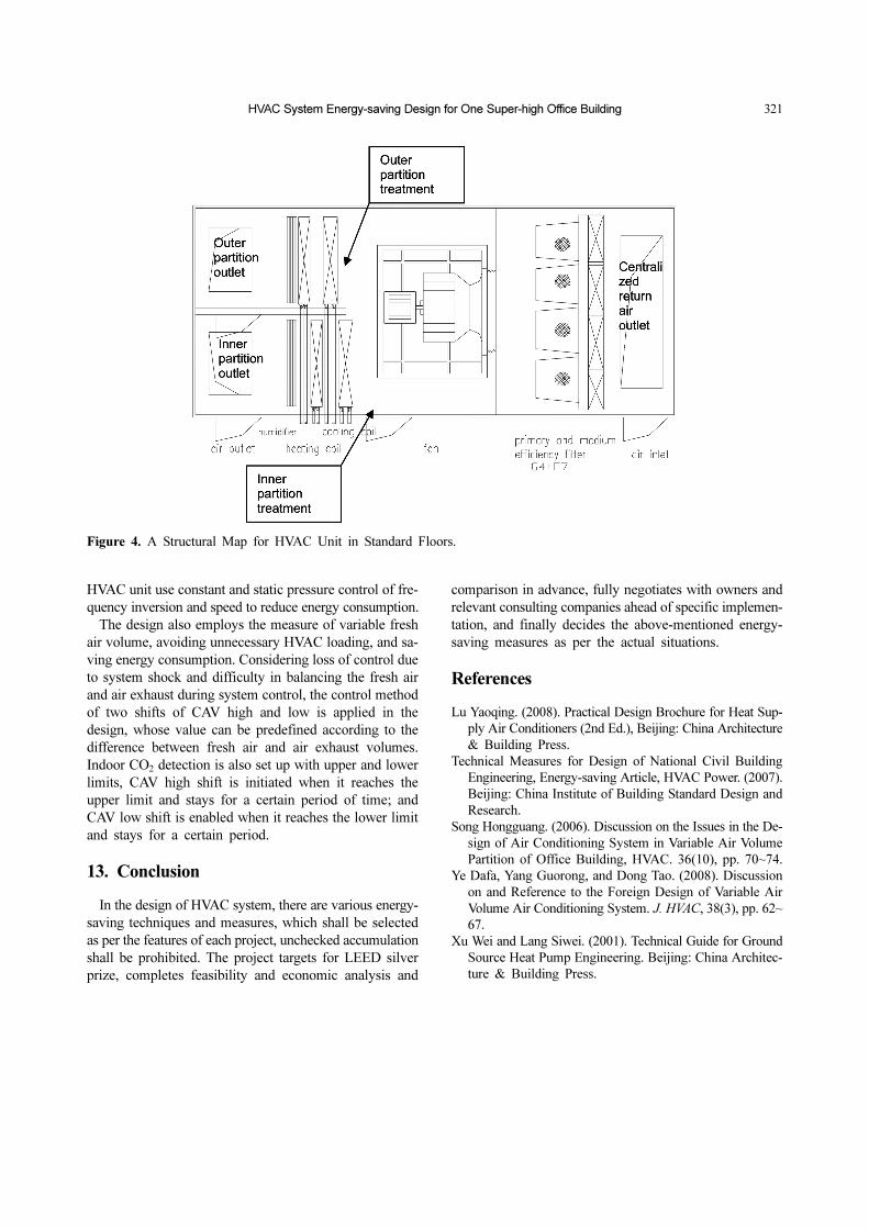
Due to the narrow machine room in standard floors, the
two systems are combined into one HVAC unit during
design. The HVAC unit uses no-volute fan, places them
in the front of HVAC unit, then installs two treatment
tunnels respectively, between which cold and hot coils
and humidifier are placed, and thus such a machine can
be used for two purposes. It eliminates the conventional
method that a VAV BOX is reheat in outer partition while
HVAC unit process goes into inner partition status, thus
avoiding the cold-hot offset during reheating in outer par-
tition, and obtaining energy saving effect.
Structural map for HVAC unit is detailed in Fig. 4.
11. Heat Recovery from Air Exhaust
For standard office floors, 2 fresh air and air exhaust
HVAC units for centralized treatment are placed in the
machine room on the 20th floor, corresponding to the
upper and lower sections. Actually, the HVAC unit is the
combination of fresh air HVAC unit and air exhaust
HVAC unit, inside of which is installed with full-heat
recovery runner in addition to fresh air pre-heating coils,
through the runner part of the energy from air exhaust is
recovered, thus HVAC load is reduced and energy con-
sumption is cut down. An air valve is installed along the
runner side respectively by fresh air and air exhaust tun-
nels. Usually all of the valves are closed during HVAC
seasonal operations to ensure the heat recovery function
of the runner; and they are started in transitional seasons
to reduce the flow resistance of the runner and cut down
the energy consumption of the fan.
12. Variable Fresh Air Volume
For fresh air and air exhaust system in standard floors,
CAV electric control valve is installed on each floor, mean-
while the fans in the centralized fresh air and air exhaust
Figure 3. Floor Plan for HVAC System in Standard Floors.
Page 8
HVAC System Energy-saving Design for One Super-high Office Building 321
HVAC unit use constant and static pressure control of fre-
quency inversion and speed to reduce energy consumption.
The design also employs the measure of variable fresh
air volume, avoiding unnecessary HVAC loading, and sa-
ving energy consumption. Considering loss of control due
to system shock and difficulty in balancing the fresh air
and air exhaust during system control, the control method
of two shifts of CAV high and low is applied in the
design, whose value can be predefined according to the
difference between fresh air and air exhaust volumes.
Indoor CO2 detection is also set up with upper and lower
limits, CAV high shift is initiated when it reaches the
upper limit and stays for a certain period of time; and
CAV low shift is enabled when it reaches the lower limit
and stays for a certain period.
13. Conclusion
In the design of HVAC system, there are various energy-
saving techniques and measures, which shall be selected
as per the features of each project, unchecked accumulation
shall be prohibited. The project targets for LEED silver
prize, completes feasibility and economic analysis and
comparison in advance, fully negotiates with owners and
relevant consulting companies ahead of specific implemen-
tation, and finally decides the above-mentioned energy-
saving measures as per the actual situations.
References
Lu Yaoqing. (2008). Practical Design Brochure for Heat Sup-
ply Air Conditioners (2nd Ed.), Beijing: China Architecture
& Building Press.
Technical Measures for Design of National Civil Building
Engineering, Energy-saving Article, HVAC Power. (2007).
Beijing: China Institute of Building Standard Design and
Research.
Song Hongguang. (2006). Discussion on the Issues in the De-
sign of Air Conditioning System in Variable Air Volume
Partition of Office Building, HVAC. 36(10), pp. 70~74.
Ye Dafa, Yang Guorong, and Dong Tao. (2008). Discussion
on and Reference to the Foreign Design of Variable Air
Volume Air Conditioning System. J. HVAC, 38(3), pp. 62~
67.
Xu Wei and Lang Siwei. (2001). Technical Guide for Ground
Source Heat Pump Engineering. Beijing: China Architec-
ture & Building Press.
Figure 4. A Structural Map for HVAC Unit in Standard Floors.