4-in-1 Arduino LCD Shield Kit PART NO. 2258873 With this project, you will have at least four products in one because this kit consists of an Arduino Uno, an LCD Shield, a USB-A to USB-B cable, and all of materials that you will need to develop the following four projects: a Counter, a Thermometer, a Capacitor Meter and a 4-Channels Voltmeter. The first of them can be developed with the materials supplied while the rest of the meters will be a reality with the help of the appropriate Shield for each of them. That is, a 4-Digit Counter, a Thermometer based on LM35 sensor for measuring in both scales: Fahrenheit and Celsius, a Capacitor Meter with a scale from 100pF - 1uF, and finally a 4- Channels Voltmeter for measuring respectively in each channel a voltage from 0V - 50V. Although you won't use together all the shields, you can stack them for showing your product as a whole. WARNING: If you are unsure of the dangers involved with your particular project, consult with someone who is experienced. Always wear eye protection and gloves. FAILURE TO INITIATE AND FOLLOW YOUR OWN SAFETY PROCEDURES MAY RESULT IN BODILY INJURY OR DEATH! Time Required: 5 hours depending on experience Experience Level: Intermediate Required tools and parts: What you will need: Soldering iron and solder Wire Cutter Needle nose pliers 22 AWG wire, 1 meter Bill of Materials: Qty Jameco SKU Component Name 1 2151486 Arduino Uno R3 DIP Edition (Revision 3) 1 222010 CABLE,USB2.0,A/B,6 FEET,BLACK,USB-A MALE TO USB-B MALE 1 2144411 DFRobot LCD Shield for Arduino 3 2152438 Arduino Uno Proto Shield (PCB only) 3 2137756 Pass-Through Female Headers for Arduino Shields - 1x8 and 1x6 Position (2 each) 1 155740 Temperature Sensor Analog Serial 2 Wire 3 Pin TO-92 Box 1 690700 Resistor Carbon Film 220 Ohm 1/4 W att 5% (In Bags of 10 and 100) 1 691817 Resistor Carbon Film 10M Ohm 1/4 W att 5% (In Bags of 10 and 100) 4 661992 Resistor Carbon Film 100k Ohm 1/2 Watt 5% (In Bags of 10 and 100) 4 691585 Resistor Carbon Film 1.0M Ohm 1/4 Watt 5% (In Bags of 10 and 100) 1 2185483 Alligator Clip Test Leads - 2 Pack Red and Black 1 2210239 16 AW G Alligator Clip Test Leads - 2 Sets of 5 Colors (10pk)
Transcript
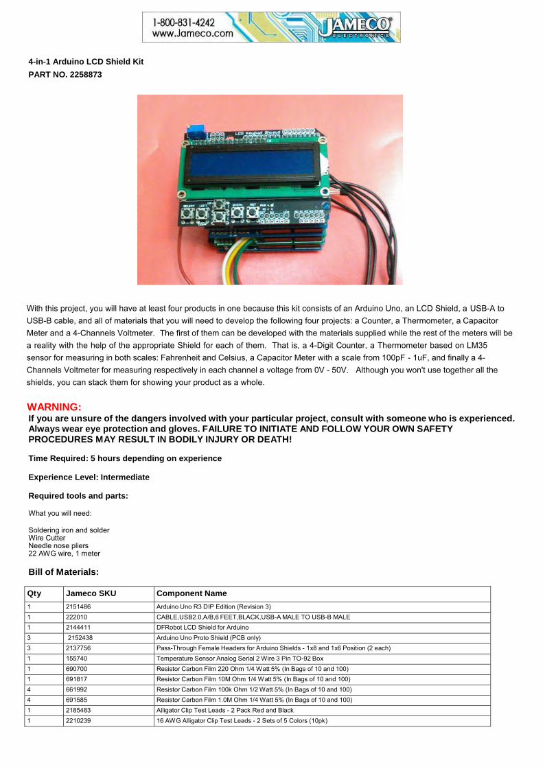
4-in-1 Arduino LCD Shield Kit PART NO. 2258873
With this project, you will have at least four products in one because this kit consists of an Arduino Uno, an LCD Shield, a USB-A to USB-B cable, and all of materials that you will need to develop the following four projects: a Counter, a Thermometer, a Capacitor Meter and a 4-Channels Voltmeter. The first of them can be developed with the materials supplied while the rest of the meters will be a reality with the help of the appropriate Shield for each of them. That is, a 4-Digit Counter, a Thermometer based on LM35 sensor for measuring in both scales: Fahrenheit and Celsius, a Capacitor Meter with a scale from 100pF - 1uF, and finally a 4-Channels Voltmeter for measuring respectively in each channel a voltage from 0V - 50V. Although you won't use together all the shields, you can stack them for showing your product as a whole.
WARNING: If you are unsure of the dangers involved with your particular project, consult with someone who is experienced. Always wear eye protection and gloves. FAILURE TO INITIATE AND FOLLOW YOUR OWN SAFETY PROCEDURES MAY RESULT IN BODILY INJURY OR DEATH!
Time Required: 5 hours depending on experience
Experience Level: Intermediate
Required tools and parts:
What you will need:
Soldering iron and solder Wire Cutter Needle nose pliers 22 AWG wire, 1 meter
Bill of Materials:
Qty Jameco SKU Component Name 1 2151486 Arduino Uno R3 DIP Edition (Revision 3) 1 222010 CABLE,USB2.0,A/B,6 FEET,BLACK,USB-A MALE TO USB-B MALE 1 2144411 DFRobot LCD Shield for Arduino 3 2152438 Arduino Uno Proto Shield (PCB only) 3 2137756 Pass-Through Female Headers for Arduino Shields - 1x8 and 1x6 Position (2 each) 1 155740 Temperature Sensor Analog Serial 2 Wire 3 Pin TO-92 Box 1 690700 Resistor Carbon Film 220 Ohm 1/4 Watt 5% (In Bags of 10 and 100) 1 691817 Resistor Carbon Film 10M Ohm 1/4 Watt 5% (In Bags of 10 and 100) 4 661992 Resistor Carbon Film 100k Ohm 1/2 Watt 5% (In Bags of 10 and 100) 4 691585 Resistor Carbon Film 1.0M Ohm 1/4 Watt 5% (In Bags of 10 and 100) 1 2185483 Alligator Clip Test Leads - 2 Pack Red and Black 1 2210239 16 AWG Alligator Clip Test Leads - 2 Sets of 5 Colors (10pk)
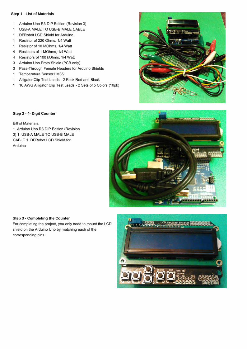
Step 1 - List of Materials
1 Arduino Uno R3 DIP Edition (Revision 3) 1 USB-A MALE TO USB-B MALE CABLE 1 DFRobot LCD Shield for Arduino 1 Resistor of 220 Ohms, 1/4 Watt 1 Resistor of 10 MOhms, 1/4 Watt 4 Resistors of 1 MOhms, 1/4 Watt 4 Resistors of 100 kOhms, 1/4 Watt 3 Arduino Uno Proto Shield (PCB only) 3 Pass-Through Female Headers for Arduino Shields1 Temperature Sensor LM35 1 Alligator Clip Test Leads - 2 Pack Red and Black 1 16 AWG Alligator Clip Test Leads - 2 Sets of 5 Colors (10pk)
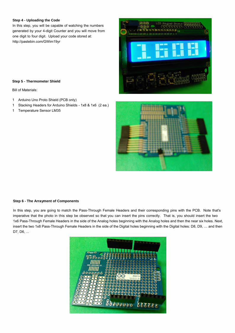
Step 2 - 4- Digit Counter
Bill of Materials: 1 Arduino Uno R3 DIP Edition (Revision 3) 1 USB-A MALE TO USB-B MALECABLE 1 DFRobot LCD Shield for Arduino
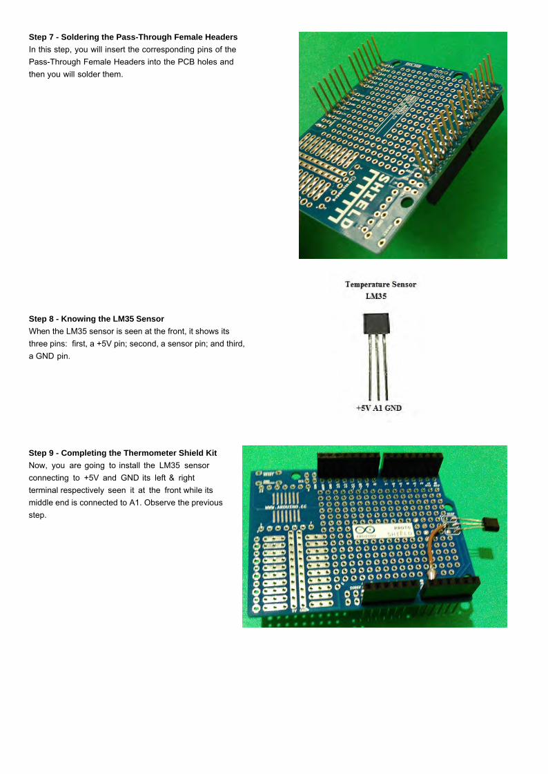
Step 3 - Completing the Counter For completing the project, you only need to mount the LCD shield on the Arduino Uno by matching each of the corresponding pins.
Step 4 - Uploading the Code In this step, you will be capable of watching the numbers generated by your 4-digit Counter and you will move from one digit to four digit. Upload your code stored at: http://pastebin.com/GWim19yr
Step 5 - Thermometer Shield
Bill of Materials:
1 Arduino Uno Proto Shield (PCB only) 1 Stacking Headers for Arduino Shields - 1x8 & 1x6 (2 ea.)1 Temperature Sensor LM35
Step 6 - The Arrayment of Components
In this step, you are going to match the Pass-Through Female Headers and their corresponding pins with the PCB. Note that's imperative that the photo in t his step be observed so that you can insert the pins correctly. That is, you should insert the two 1x6 Pass-Through Female Headers in the side of the Analog holes beginning with the Analog holes and then the near six holes. Next, insert the two 1x8 Pass-Through Female Headers in the side of the Digital holes beginning with the Digital holes: D8, D9, … and then D7, D6, ...
Step 7 - Soldering the Pass-Through Female Headers In this step, you will insert the corresponding pins of the Pass-Through Female Headers into the PCB holes and then you will solder them.
Step 8 - Knowing the LM35 Sensor When the LM35 sensor is seen at the front, it shows its three pins: first, a +5V pin; second, a sensor pin; and third, a GND pin.
Step 9 - Completing the Thermometer Shield Kit Now, you are going to install the LM35 sensor connecting to +5V and GND its left & right terminal respectively seen it at the front while its middle end is connected to A1. Observe the previous step.
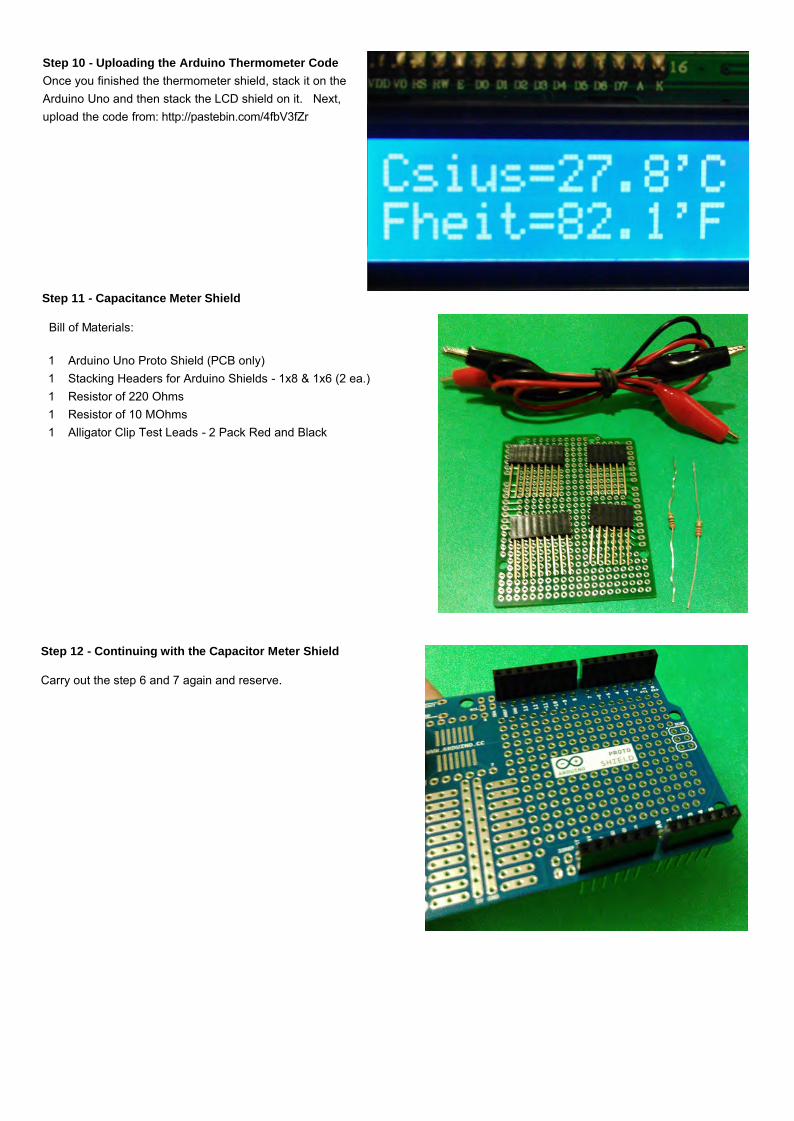
Step 10 - Uploading the Arduino Thermometer Code Once you finished the thermometer shield, stack it on the Arduino Uno and then stack the LCD shield on it. Next, upload the code from: http://pastebin.com/4fbV3fZr
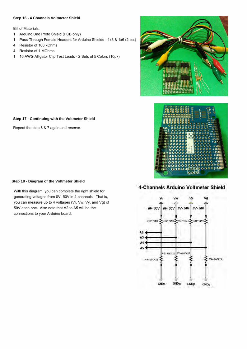
Step 11 - Capacitance Meter Shield
Bill of Materials:
1 Arduino Uno Proto Shield (PCB only) 1 Stacking Headers for Arduino Shields - 1x8 & 1x6 (2 ea.) 1 Resistor of 220 Ohms 1 Resistor of 10 MOhms 1 Alligator Clip Test Leads - 2 Pack Red and Black
Step 12 - Continuing with the Capacitor Meter Shield
Step 13 - Schematic Diagram of the Capacitor Shield Kit Check the diagram of your shield and do the connections showed on it.
Step 14 - Completing the Capacitance Meter Shield
For completing the shield, follow the instructions in the previous step. That is, connect an end of each resistor to A1 where you will also draw the positive terminal of probe of this shield. Now, connect the remaining terminal of the resistor of 10 MOhms to D2 while the remaining lead of the resistor of 220 Ohms to D3. Finally, draw the negative terminal of probe from GND.
Step 15 - Installing the Capacitor Meter Shield Once you finished the capacitor meter shield, stack it on the Arduino Uno and then stack the LCD shield on it. Next, upload the code from: http://pastebin.com/VvKrRwVk
Step 16 - 4 Channels Voltmeter Shield
Bill of Materials: 1 Arduino Uno Proto Shield (PCB only) 1 Pass-Through Female Headers for Arduino Shields - 1x8 & 1x6 (2 ea.) 4 Resistor of 100 kOhms 4 Resistor of 1 MOhms 1 16 AWG Alligator Clip Test Leads - 2 Sets of 5 Colors (10pk)
Step 17 - Continuing with the Voltmeter Shield
Repeat the step 6 & 7 again and reserve.
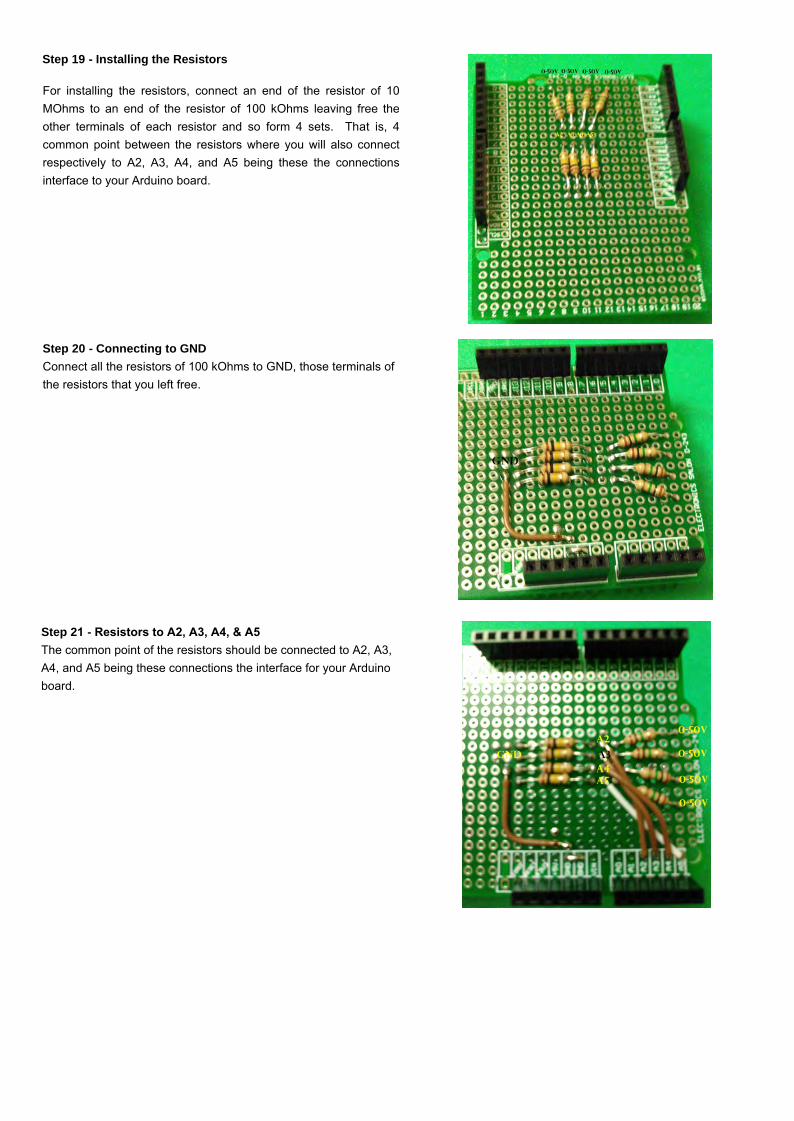
Step 18 - Diagram of the Voltmeter Shield
With this diagram, you can complete the right shield for generating voltages from 0V- 50V in 4-channels. That is, you can measure up to 4 voltages (Vr, Vw, Vy, and Vg) of 50V each one. Also note that A2 to A5 will be the connections to your Arduino board.
For installing the resistors, connect an end of the resistor of 10 MOhms to an end of the resistor of 100 kOhms leaving free the other terminals of each resistor and so form 4 sets. That is, 4 common point between the resistors where you will also connect respectively to A2, A3, A4, and A5 being these the connections interface to your Arduino board.
Step 20 - Connecting to GND Connect all the resistors of 100 kOhms to GND, those terminals of the resistors that you left free.
Step 21 - Resistors to A2, A3, A4, & A5The common point of the resistors should be connected to A2, A3, A4, and A5 being these connections the interface for your Arduino board.
Step 22 - Installing The Color Alligator Clips
The terminals that left free of those resistors of 1MΩ connect them to red, white, yellow, and green alligerators being these the voltages: Vr(0V-50V), Vw(0V-50V), Vy(0V-50V), and Vg(0V-50V) while the others corresponding leads of the resistors are those connected to A2, A3, A4, and A5 respectively.
Step 23 - Installing The Black Alligator ClipsFor installing the black alligator clips, connect them to GND. Once connected the last alligator clips, you will have completed all the outputs of voltage: Vr (0.50V), Vw (0V-50V), Vy (0V-50V), Vg (0V-50V).
Step 24 - Uploading The Arduino Voltmeter CodeOnce finished the voltmeter shield, stack it on the Arduino Uno and then stack the LCD shield on it. Next, upload the code at: http://pastebin.com/3XEfV0uu