Dublin Institute of Technology Dr. Gerald Farrell Optical Communications Systems School of Electronic and Communications Engineering Unauthorised usage or reproduction strictly prohibited Copyright 2002, Dr. Gerald Farrell, Dublin Institute of Technology Semiconductor Laser Diodes 27/02/02 2.4 Semicdr Laser diode structures and characteristics.prz
Transcript
Dublin Institute of Technology
Dr. Gerald Farrell
Optical Communications Systems
School of Electronic and Communications Engineering
Unauthorised usage or reproduction strictly prohibitedCopyright 2002, Dr. Gerald Farrell, Dublin Institute of Technology
Semiconductor Laser Diodes
27/02/02 2.4 Semicdr Laser diode structures and characteristics.prz
Optical Communications Systems, Dr. Gerald Farrell, School of Electronic and Communications Engineering
Unauthorised usage or reproduction strictly prohibited, Copyright 2002, Dr. Gerald Farrell, Dublin Institute of Technology
Laser Structures
Source: Master 4_3
27/02/02 2.4 Semicdr Laser diode structures and characteristics.prz
Optical Communications Systems, Dr. Gerald Farrell, School of Electronic and Communications Engineering
Unauthorised usage or reproduction strictly prohibited, Copyright 2002, Dr. Gerald Farrell, Dublin Institute of Technology
Semiconductor Laser Structures
A wide variety of laser structures have evolved, with the aim of reduced thresholds, improved efficiency and narrow spectral output:
Basic broad area laser
Stripe geometry laser
Gain guided laser
Index guided laser
Single frequency laser
Multi-section laser
Source: Master 4_3
27/02/02 2.4 Semicdr Laser diode structures and characteristics.prz
Optical Communications Systems, Dr. Gerald Farrell, School of Electronic and Communications Engineering
Unauthorised usage or reproduction strictly prohibited, Copyright 2002, Dr. Gerald Farrell, Dublin Institute of Technology
Double Heterostructure
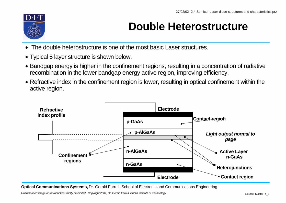
The double heterostructure is one of the most basic Laser structures.
Typical 5 layer structure is shown below.
Bandgap energy is higher in the confinement regions, resulting in a concentration of radiative recombination in the lower bandgap energy active region, improving efficiency.
Refractive index in the confinement region is lower, resulting in optical confinement within the active region.
Contact region
Contact region
p-GaAs
p-AlGaAs
Active Layer n-GaAs
n-AlGaAs
n-GaAs
Electrode
Heterojunctions
Light output normal to page
Confinement regions
Electrode
Refractive index profile
Source: Master 4_3
27/02/02 2.4 Semicdr Laser diode structures and characteristics.prz
Optical Communications Systems, Dr. Gerald Farrell, School of Electronic and Communications Engineering
Unauthorised usage or reproduction strictly prohibited, Copyright 2002, Dr. Gerald Farrell, Dublin Institute of Technology
Broad Area DH Injection Lasers
Roughened sides
n-AlGaAs
Light Output
Cleaved Mirror
n+ -GaAs
p -AlGaAs
n+ -GaAs
Confinement Layers
Contact metallization
p -GaAs Active Layer
In this simple early laser structure the DH structure confines the light to the active region in the vertical direction.Lasing still takes place across the whole width of the device, hence it is called a broad area laser.Low quantum efficiency, by comparison with more advanced designs, resulting in high threshold current values.Output light geometry is unsuitable for coupling to fibre.
Source: Master 4_3
27/02/02 2.4 Semicdr Laser diode structures and characteristics.prz
Optical Communications Systems, Dr. Gerald Farrell, School of Electronic and Communications Engineering
Unauthorised usage or reproduction strictly prohibited, Copyright 2002, Dr. Gerald Farrell, Dublin Institute of Technology
Gain Guided Lasers
Laser structures are designed to keep the threshold as low as possible, with a high efficiency and a narrow output beam.
Two basic design approaches are gain guiding and index guiding.
In a gain guided laser the current flow is restricted to a narrow stripe by placing high resistivity regions within the contact regions.
Gain guiding is not very successful, thresholds are high, >100mA, with low differential quantum efficiencies and non-linear kinks in the output characteristic.
p-GaAs
p-AlGaAs
Active Layer n-GaAs
n-AlGaAs
n-GaAs
Electrode
Heterojunctions
Confinement regions
Electrode
High resistivity region
Source: Master 4_3
27/02/02 2.4 Semicdr Laser diode structures and characteristics.prz
Optical Communications Systems, Dr. Gerald Farrell, School of Electronic and Communications Engineering
Unauthorised usage or reproduction strictly prohibited, Copyright 2002, Dr. Gerald Farrell, Dublin Institute of Technology
DH Stripe Geometry Lasers
Stripe formed by inclusion of insulation layers, thus most of the current enters the active region in a narrow stripe that runs the length of the device.
Result is a narrow emission region, with a lower lasing threshold and a narrower output beam.
Source: Master 4_3
27/02/02 2.4 Semicdr Laser diode structures and characteristics.prz
Optical Communications Systems, Dr. Gerald Farrell, School of Electronic and Communications Engineering
Unauthorised usage or reproduction strictly prohibited, Copyright 2002, Dr. Gerald Farrell, Dublin Institute of Technology
Index Guided Lasers
Index guiding overcomes most of the disadvantages of gain guided designs.
In an index guided structure the active region is surrounded by a region of lower refractive index, confining the photons to a narrow stripe, in both the transverse and vertical directions.
Several designs have emerged including the ridge waveguide (weakly index guided) and buried heterostructure (BH) (fully index guided) designs.
Typically the threshold currents lie in the region of 10-20 mA for BH lasers, with active regions a couple of microns wide.
Buried heterostructure laser diode
Source: Master 4_3
27/02/02 2.4 Semicdr Laser diode structures and characteristics.prz
Optical Communications Systems, Dr. Gerald Farrell, School of Electronic and Communications Engineering
Unauthorised usage or reproduction strictly prohibited, Copyright 2002, Dr. Gerald Farrell, Dublin Institute of Technology
Twin Section Lasers
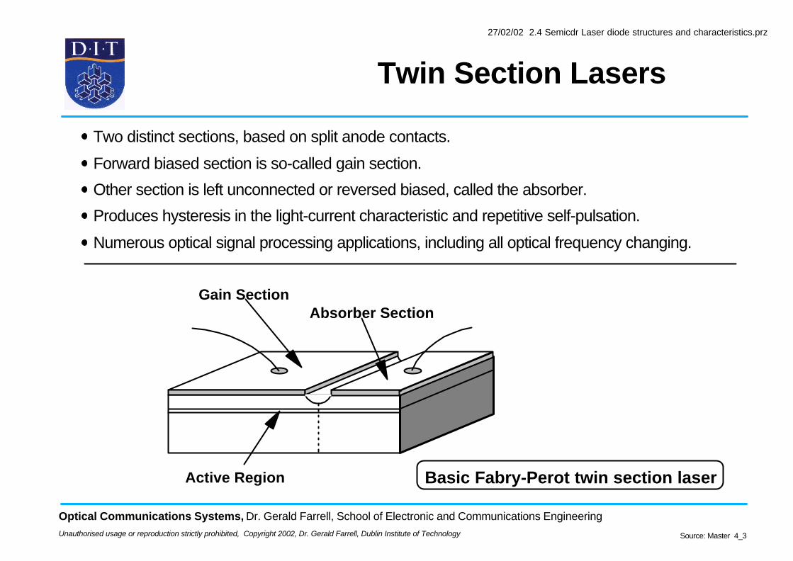
Gain SectionAbsorber Section
Active Region
Two distinct sections, based on split anode contacts.
Forward biased section is so-called gain section.
Other section is left unconnected or reversed biased, called the absorber.
Produces hysteresis in the light-current characteristic and repetitive self-pulsation.
Numerous optical signal processing applications, including all optical frequency changing.
Basic Fabry-Perot twin section laser
Source: Master 4_3
27/02/02 2.4 Semicdr Laser diode structures and characteristics.prz
Optical Communications Systems, Dr. Gerald Farrell, School of Electronic and Communications Engineering
Unauthorised usage or reproduction strictly prohibited, Copyright 2002, Dr. Gerald Farrell, Dublin Institute of Technology
Results in two distinct states, potentially useful for optical memory and logic
5 mV/div
1 ns/div
O/P
I/P
Twin section lasers can also exhibit repetitive on-off behaviour, called self-pulsation.
Proposed applications include all-optical synchronisation for frequency multiplication / division and clock extraction.
Trace shows all-optical frequency multiplication by 2:1
Source: Master 4_3
27/02/02 2.4 Semicdr Laser diode structures and characteristics.prz
Optical Communications Systems, Dr. Gerald Farrell, School of Electronic and Communications Engineering
Unauthorised usage or reproduction strictly prohibited, Copyright 2002, Dr. Gerald Farrell, Dublin Institute of Technology
Laser Characteristics
Source: Master 4_3
27/02/02 2.4 Semicdr Laser diode structures and characteristics.prz
Optical Communications Systems, Dr. Gerald Farrell, School of Electronic and Communications Engineering
Unauthorised usage or reproduction strictly prohibited, Copyright 2002, Dr. Gerald Farrell, Dublin Institute of Technology
Laser Efficiency
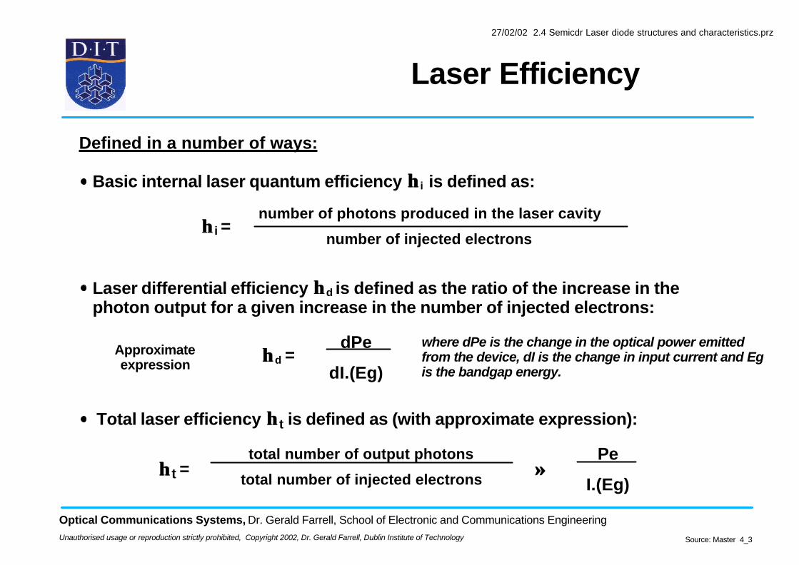
Basic internal laser quantum efficiency ηη i is defined as:
ηη i = number of photons produced in the laser cavity
number of injected electrons
Defined in a number of ways:
Laser differential efficiency ηηd is defined as the ratio of the increase in the photon output for a given increase in the number of injected electrons:
ηηd = Approximate expression
dPe
dI.(Eg)
where dPe is the change in the optical power emitted from the device, dI is the change in input current and Eg is the bandgap energy.
Total laser efficiency ηηt is defined as (with approximate expression):
ηηt = total number of output photons
total number of injected electrons
Pe
I.(Eg)≈≈
Source: Master 4_3
27/02/02 2.4 Semicdr Laser diode structures and characteristics.prz
Optical Communications Systems, Dr. Gerald Farrell, School of Electronic and Communications Engineering
Unauthorised usage or reproduction strictly prohibited, Copyright 2002, Dr. Gerald Farrell, Dublin Institute of Technology
Laser Characteristics: Threshold
Spontaneous emission regime
Stimulated emission regime
Light output
Injection current
Laser threshold current
Saturation
All Semiconductor laser diodes have a light current characteristic, with a defined threshold current.
Below the threshold spontaneous emission dominates
Beyond the threshold, where stimulated emission dominates, the differential quantum efficiency increase dramatically.
The threshold current by convention is the intercept on the current axis of a line drawn along the characteristic, as shown
Source: Master 4_3
27/02/02 2.4 Semicdr Laser diode structures and characteristics.prz
Optical Communications Systems, Dr. Gerald Farrell, School of Electronic and Communications Engineering
Unauthorised usage or reproduction strictly prohibited, Copyright 2002, Dr. Gerald Farrell, Dublin Institute of Technology
Temperature Dependence (I)
The threshold current is highly temperature dependent.
The temperature dependence of the laser threshold is proportional to T/To.
T is the absolute temperature in degrees Kelvin
To is the so called characteristic temperature
To depends on the active region material.
Light output versus input current characteristic at various temperatures for
an InGaAsP laser
0 10 20 30 40 50 60 70 80
10 mW
7.5 mW
5 mW
2.5 mW
0 mW
DC current (mA)
10 20 30 40 50 60
Laser temperature in degrees C
Light Output
Source: Master 4_3
27/02/02 2.4 Semicdr Laser diode structures and characteristics.prz
Optical Communications Systems, Dr. Gerald Farrell, School of Electronic and Communications Engineering
Unauthorised usage or reproduction strictly prohibited, Copyright 2002, Dr. Gerald Farrell, Dublin Institute of Technology
Temperature Dependence (II)
In general the threshold current density Jth temperature dependence is :
Light output versus input current characteristic at various temperatures for an InGaAsP laser
0 10 20 30 40 50 60 70 80
10 mW
7.5 mW
5 mW
2.5 mW
0 mW
DC current (mA)
10 20 30 40 50 60
Laser temperature in degrees C
Light Output
Jth is proportional to exp T To
To is about 120 to 190 degrees K for AlGaAs devices,
InGaAsP devices have a stronger dependence with To values of 40 to 75 degrees K
Source: Master 4_3
27/02/02 2.4 Semicdr Laser diode structures and characteristics.prz
Optical Communications Systems, Dr. Gerald Farrell, School of Electronic and Communications Engineering
Unauthorised usage or reproduction strictly prohibited, Copyright 2002, Dr. Gerald Farrell, Dublin Institute of Technology
Temperature Dependence Problem
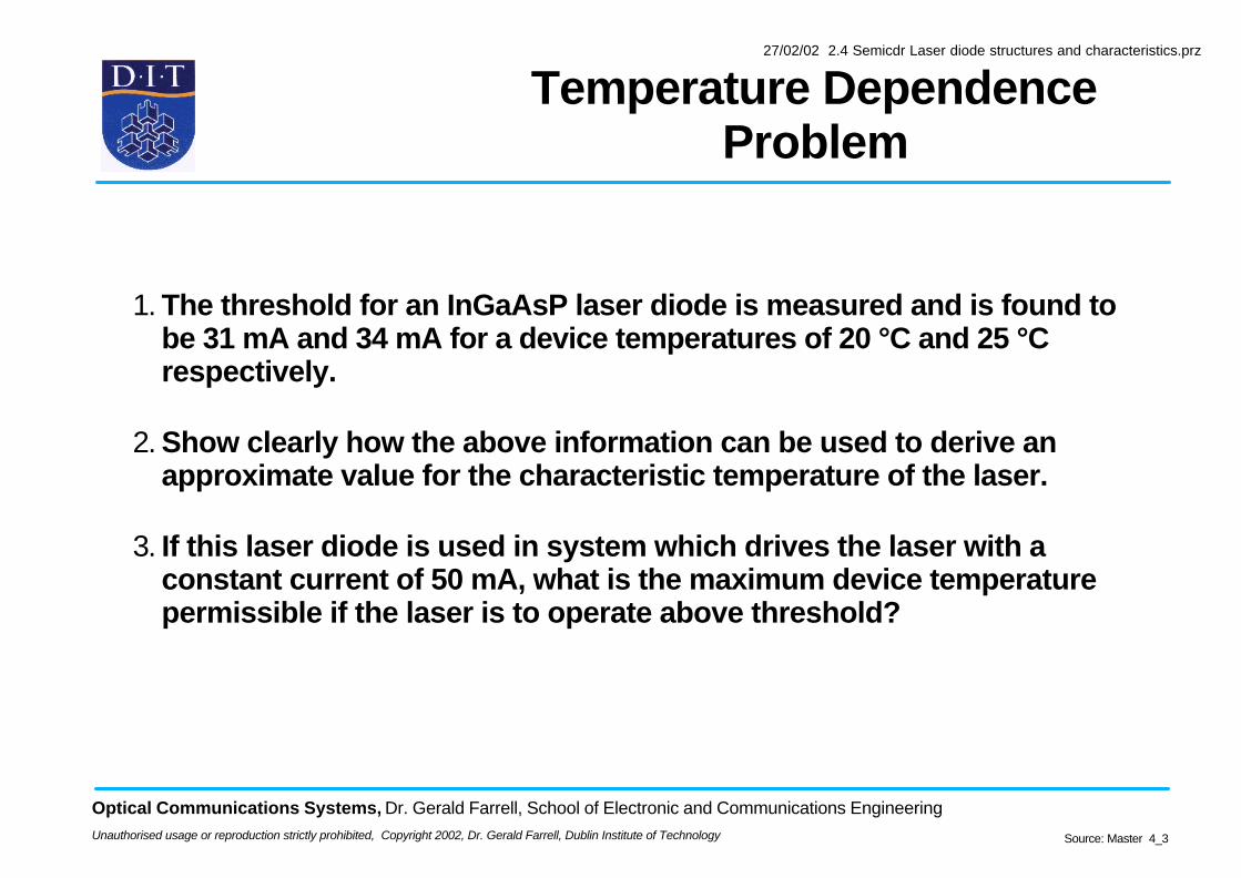
1. The threshold for an InGaAsP laser diode is measured and is found to be 31 mA and 34 mA for a device temperatures of 20 °C and 25 °C respectively.
2. Show clearly how the above information can be used to derive an approximate value for the characteristic temperature of the laser.
3. If this laser diode is used in system which drives the laser with a constant current of 50 mA, what is the maximum device temperature permissible if the laser is to operate above threshold?
Source: Master 4_3
27/02/02 2.4 Semicdr Laser diode structures and characteristics.prz
Optical Communications Systems, Dr. Gerald Farrell, School of Electronic and Communications Engineering
Unauthorised usage or reproduction strictly prohibited, Copyright 2002, Dr. Gerald Farrell, Dublin Institute of Technology
Temperature Dependence Solution (I)
Source: Master 4_3
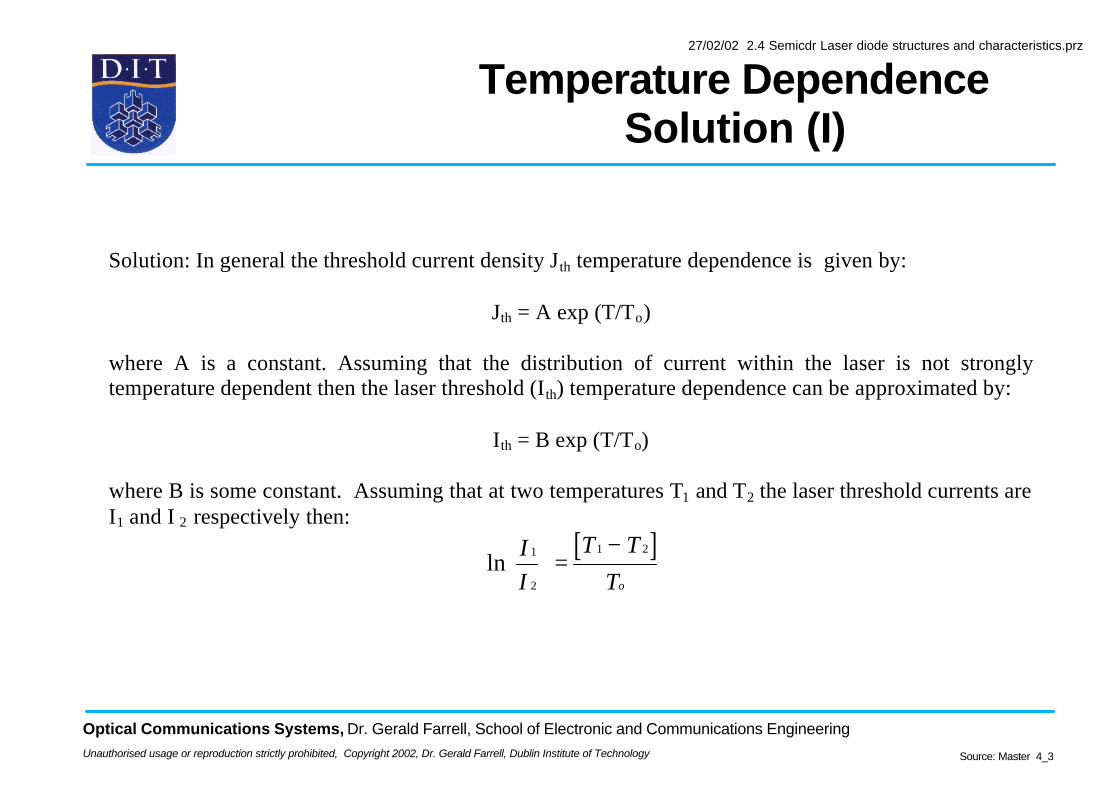
Solution: In general the threshold current density Jth temperature dependence is given by:
Jth = A exp (T/To)
where A is a constant. Assuming that the distribution of current within the laser is not stronglytemperature dependent then the laser threshold (Ith) temperature dependence can be approximated by:
Ith = B exp (T/To)
where B is some constant. Assuming that at two temperatures T1 and T2 the laser threshold currents areI1 and I 2 respectively then:
[ ]ln
I
I
T T
To
1
2
1 2
=−
27/02/02 2.4 Semicdr Laser diode structures and characteristics.prz
Optical Communications Systems, Dr. Gerald Farrell, School of Electronic and Communications Engineering
Unauthorised usage or reproduction strictly prohibited, Copyright 2002, Dr. Gerald Farrell, Dublin Institute of Technology
Temperature Dependence Solution (II)
Source: Master 4_3
Based on the measurements provided the value of To, the characteristic temperature is 54.1 °K. If thedevice is to lase at 50 mA, then the threshold must be less than 50 mA. If the maximum temperature atwhich lasing will occur is Tx then (temperatures in °K) :
[ ]o
x
T
T
mA
mA 298
34
50ln
−=
Substituting for To and solving for Tx gives Tx = 318.8 °K or 45.8 °C.
27/02/02 2.4 Semicdr Laser diode structures and characteristics.prz
Optical Communications Systems, Dr. Gerald Farrell, School of Electronic and Communications Engineering
Unauthorised usage or reproduction strictly prohibited, Copyright 2002, Dr. Gerald Farrell, Dublin Institute of Technology
Laser Diode Optical Spectrum
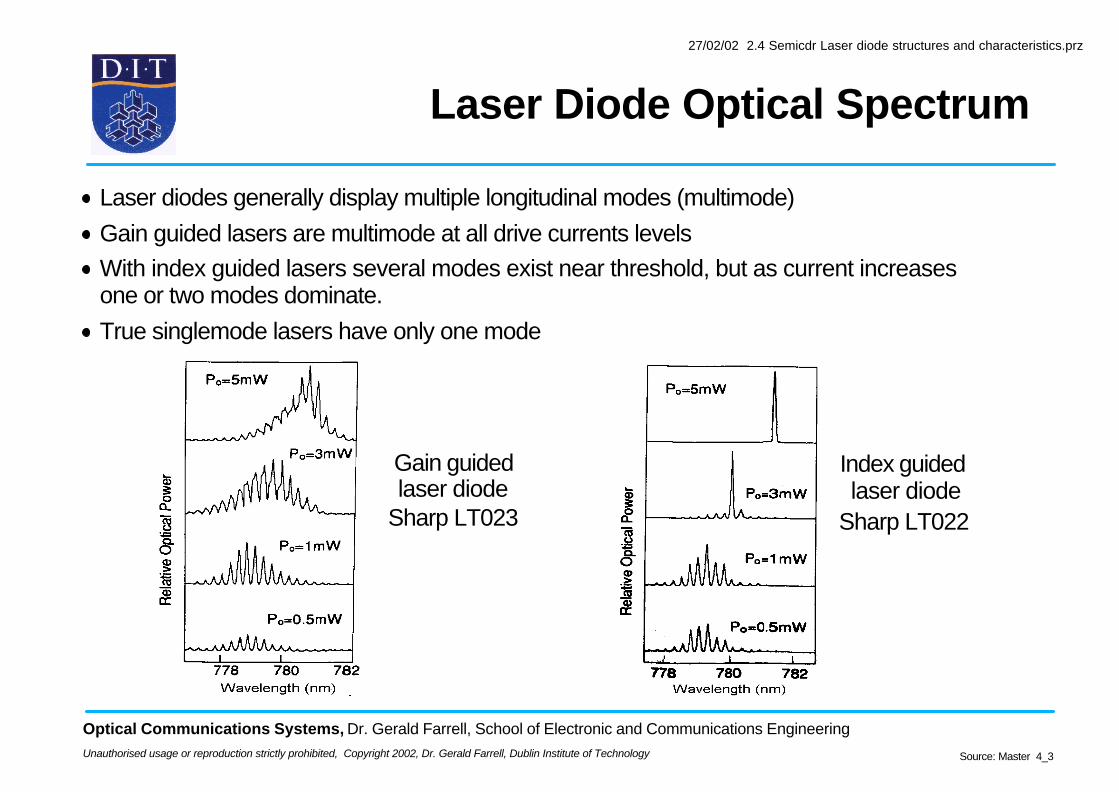
Laser diodes generally display multiple longitudinal modes (multimode)
Gain guided lasers are multimode at all drive currents levels
With index guided lasers several modes exist near threshold, but as current increases one or two modes dominate.
True singlemode lasers have only one mode
Index guided laser diode
Sharp LT022
Gain guided laser diode
Sharp LT023
Source: Master 4_3
27/02/02 2.4 Semicdr Laser diode structures and characteristics.prz
Optical Communications Systems, Dr. Gerald Farrell, School of Electronic and Communications Engineering
Unauthorised usage or reproduction strictly prohibited, Copyright 2002, Dr. Gerald Farrell, Dublin Institute of Technology
Single Frequency Lasers
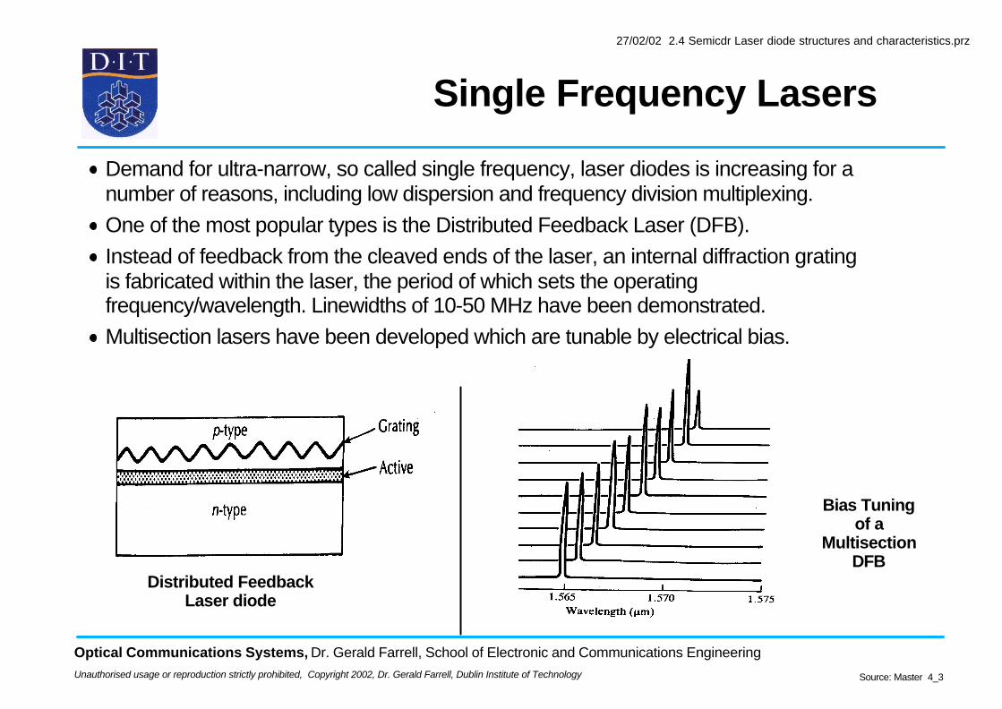
Demand for ultra-narrow, so called single frequency, laser diodes is increasing for a number of reasons, including low dispersion and frequency division multiplexing.
One of the most popular types is the Distributed Feedback Laser (DFB).
Instead of feedback from the cleaved ends of the laser, an internal diffraction grating is fabricated within the laser, the period of which sets the operating frequency/wavelength. Linewidths of 10-50 MHz have been demonstrated.
Multisection lasers have been developed which are tunable by electrical bias.
Distributed Feedback Laser diode
Bias Tuning of a
Multisection DFB
Source: Master 4_3
27/02/02 2.4 Semicdr Laser diode structures and characteristics.prz
Optical Communications Systems, Dr. Gerald Farrell, School of Electronic and Communications Engineering
Unauthorised usage or reproduction strictly prohibited, Copyright 2002, Dr. Gerald Farrell, Dublin Institute of Technology
Laser Modulation Bandwidth
All semiconductor laser diodes exhibit a so-called relaxation oscillation
Current pulse injected into the laser produces an optical output pulse exhibiting relaxation oscillation
Relaxation oscillation can be seen as a resonance frequency for the interchange of energy between photons and carriers
Relaxation oscillation normally sets the limit on the modulation frequency of the laser (0.5 to 10 GHz)
time
Current pulse input to laser
time
Optical pulse, with relaxation oscillation
Source: Master 4_3
27/02/02 2.4 Semicdr Laser diode structures and characteristics.prz