4. multimedia platforms with DirectX 9 digital convergence becomes a reality learning objectives After reading this chapter you should be able to characterize the functionality of current multimedia platforms, to describe the capabilities of GPUs, to mention the components of the Microsoft DirectX 9 SDK, and to discuss how to integrate 3D and video. Almost 15 years ago I bought my first multimedia PC, with Windows 3.1 Media Edition. This setup included a video capture card and a 4K baud modem. It was, if I remember well, a 100 Mhz machine, with 16 Mb memory and a 100 Mb disk. At that time, expensive as it was, the best I could afford. Some 4 years later, I acquired a Sun Sparc 1 multimedia workstation, with a video capture card and 3D hardware accelerator. It allowed for programming OpenGL in C++ with the GNU gcc compiler, and I could do live video texture mapping at a frame rate of about one per second. If you consider what is common nowadays, a 3Ghz machine with powerful GPU, 1 Gb of memory, a 1.5Mb cable or ADSL connection and over 100 Gb of disk space, you realize what progress has been made over the last 10 years. In this chapter, we will look in more detail at the capability of current multi- media platforms, and we will explore the functionality of the Microsoft DirectX 0 platform. In the final section of this chapter, I will then report about the work I did with the DirectX 9 SDK to implement the ViP system, a presentation system that merges video and 3D. 1 1
Transcript
4. multimedia platforms
with DirectX 9 digital convergence becomes a reality
learning objectives
After reading this chapter you should be able to characterize the functionalityof current multimedia platforms, to describe the capabilities of GPUs, tomention the components of the Microsoft DirectX 9 SDK, and to discusshow to integrate 3D and video.
Almost 15 years ago I bought my first multimedia PC, with Windows 3.1Media Edition. This setup included a video capture card and a 4K baud modem.It was, if I remember well, a 100 Mhz machine, with 16 Mb memory and a 100Mb disk. At that time, expensive as it was, the best I could afford. Some 4 yearslater, I acquired a Sun Sparc 1 multimedia workstation, with a video capture cardand 3D hardware accelerator. It allowed for programming OpenGL in C++ withthe GNU gcc compiler, and I could do live video texture mapping at a framerate of about one per second. If you consider what is common nowadays, a 3Ghzmachine with powerful GPU, 1 Gb of memory, a 1.5Mb cable or ADSL connectionand over 100 Gb of disk space, you realize what progress has been made over thelast 10 years.
In this chapter, we will look in more detail at the capability of current multi-media platforms, and we will explore the functionality of the Microsoft DirectX 0platform. In the final section of this chapter, I will then report about the work Idid with the DirectX 9 SDK to implement the ViP system, a presentation systemthat merges video and 3D.
1
1
2 multimedia platforms
4.1 developments in hardware and software
Following Moore’s law (predicting the doubling of computing power every eigh-teen months), computer hardware has significantly improved. But perhaps morespectacular is the growth in computing power of dedicated multimedia hard-ware, in particular what is nowadays called the GPU (graphics processing unit).In Fernando and Kilgard (2003), he NVIDIA GeForce FX GPU is said to have125 million of transistors, whereas the Intel 2.4GHz Pentium 4 contains only 55million of transistors. Now, given the fact that the CPU (central processing unit)is a general purpose, or as some may like to call it, universal device, why is itnecessary or desirable to have such specialized hardware, GPUs for graphics and,to be complete DSPs (digital signal processors) for audio?
a little bit of history
Almost everyone knows the stunning animation and effects in movies made pos-sible by computer graphics, as for example the latest production of Pixar, TheIncredibles. Such animation and effects are only possible by offline rendering,using factories of thousands of CPUs, crunching day and night to render all theframes.
At the basis of rendering lies traditional computer graphics technology. Thatis, the transformation of vertices (points in 3D space), rasterization (that isdetermining the pixel locations and pixel properties corresponding to the vertices),and finally the so-called raster operations (determining whether and how thepixels are written to the framebuffer). OpenGL, developed by SGI was the firstcommonly available software API (application programmers interface) to controlthe process of rendering. Later, Microsoft introduced Direct3D as an alternativefor game programming on the PC platform.
The process outlined above is called the graphics pipeline. You put models,that is collections of vertices, in and you get (frames of) pixels out. This is indeed asimplification in that it does not explain how, for example, animation and lightingeffects are obtained. To gain control over the computation done in the graphicspipeline, Pixar developed Renderman, which allows for specifying transformationson the models (vertices) as well as operations on the pixels (or fragments as theyare called in Fernando and Kilgard (2003)) in a high level language. As vertexoperations you may think of for example distortions of shape due to a force such asan explosion. As pixel operations, the coloring of pixels using textures (images)or special lighting and material properties. The languages for specifying suchvertex or pixel operations are collectively called shader languages. Using offlinerendering, almost anything is possible, as long as you specify it mathematicallyin a computationally feasible way.
The breakthrough in computer graphics hardware was to make such shadinglanguages available for real-time computer graphics, in a way that allows, as Fer-nando and Kilgard (2003) phrase it, 3D game and application programmers andreal-time 3D artists to use it in an effective way.
Leading to the programmable computer graphics hardware that we know
developments in hardware and software 3
today, Fernando and Kilgard (2003) distinguish between four generations of 3Daccellerators.1
4 generations of GPU
• Before the introduction of the GPU, there only existed very expensive specializedhardware such as the machines from SGI.
• The first generation of GPU, including NVIDIA TNT2, ATI Rage and 3dfxVoodoo3, only supported rasterizing pre-transformed triangles and some limitedtexture operations.
• The second generation of GPUs, which were introduced around 1999, includedthe NVIDIA GeForce 2 and ATI Radeon 7500. They allowed for both 3D vertextransformations and some lighting, conformant with OpenGL and DirectX 7.
• The tird generation GPUs, including NVIDIA GeForce 3, Microsoft Xbox andATI Radeon 8500, included both powerful vertex processing capabilities and somepixel-based configuration operations, exceeding those of OpenGL and DirectX 7.
• Finally, the fourth generation of GPUs, such as the NVIDIA GeForce FX and ATIRadeon 9700, allow for both complex vertex and pixel operations.
The capabilities of these latter generations GPUs motivated the development ofhigh level shader languages, such as NVIDIA Cg and Microsoft HLSL. High leveldedicated graphics hardware programming languages to control what may becalled the programmable graphics pipeline.
the (programmable) graphics pipelineBefore discussing shading languages any further, let’s look in some more detail atthe graphics pipeline. But before that you must have an intuitive grasp of whatis involved in rendering a scene.
Just imagine that you have created a model, say a teapot, in your favoritetool, for example Maya or 3D Studio Max. Such a model may be regardedas consisting of polygons, let’s say triangles, and each vertex (point) of thesetriangles has apart from its position in (local) 3D space also a color. To render thismodel it must first be positioned in your scene, using so-called world coordinates.The world transformation is used to do this. The world transformation maychange the position, rotation and scale of your object/model. Since your scene islooked at from one particular point of view we need to apply also a so-called viewtransformation, and to define how our view will be projected on a 2D plane, wemust specify a projection transformation. Without going into the mathematicaldetails, we may observe that these transformations can be expressed as 4x4matrices and be combined in a single matrix, often referred to as the world viewprojection matrix, that can be applied to each of the vertices of our model. Thiscombined transformation is the first stage in the process of rendering:
1 The phrase GPU was introduced by NVIDIA to indicate that the capabilities of the GPUfar exceed those of the VGA (video graphics array) originally introduced by IBM, which isnothing more than a dumb framebuffer, requiring updates from the CPU.
4 multimedia platforms
2. assembly and rasterization – combine, clip and determine pixel locations
3. fragment texturing and coloring – determine pixel colors
4. raster operations – update pixel values
The second phase, roughly, consists of cleaning up the collection of (transformed)vertices and determining the pixel locations that correspond to the model. Then,in the third phase, using interpolation or some more advanced method, coloringand lighting is applied, and finally a sequence of per-fragment or pixel operationsis applied. Both OpenGL and Direct3D support among others an alpha (ortransparency) test, a depth test and blending. The above characterized the fixedfunction graphics pipeline. Both the OpenGL and Direct3D API support the fixedfunction pipeline, offering many ways to set relevant parameters for, for example,applying lights, depth and texturing operations.
To understand what the programmable graphics pipeline can do for you, youwould best look at some simple shader programs. In essence, the programmablepipeline allows you to perform arbitrary vertex operations and (almost) arbitrarypixel operations. For example, you can apply a time dependent morphing opera-tion to your model. Or you can apply an amplification to the colors of your scene.But perhaps more interestingly, you can also apply an advanced lighting modelto increase realism.
A simple morphing shader in ViP, see section 4.3.2
a simple shader
When I began with programming shaders myself, I started with looking at ex-amples from the DirectX SDK. Usually these examples were quite complex, andmy attempt at modifying them often failed. Being raised in theoretical computerscience, I changed strategy and developed my first shader program called id, whichdid nothing. Well, it just acted as the identity function. Then later I used thisprogram as a starting point for writing more complex shader programs.
The id shader program is written in the DirectX 9 HLSL (high level shaderlanguage), and makes use of the DirectX Effects framework, which allows forspecifying multiple vertex and pixel shaders, as well as multiple techniques andmultiple passes in a single file.
developments in hardware and software 5
The program starts with a declaration, specifying the global names for respec-tively the texture and the world/view/projection matrix. Also a texture sampleris declared, of which the function will become clear later.
HLSL declarations
texture tex;float4x4 wvp; // World * View * Projection matrix
sampler tex sampler = sampler state{
texture = /<tex/>;};
It then defines, respectively, the vertex shader input and output, as structures.This declaration follows the standard C-like syntax for specifying elements in astructure, except for the identifiers in capitals, which indicate the semantics ofthe fields, corresponding to pre-defined registers in the GPU data flow.
vertex shader data flow
struct vsinput {float4 position : POSITION;float3 normal : NORMAL;float2 uv : TEXCOORD0;
When the vs id function, given below, is called, the input arguments are filledby the registers corresponding to the semantics pf the input structure. Similarly,the output results in setting the registers corresponding to the semantics of theoutput structure.
The vs id function does exactly what the fixed graphics pipeline would do whentransforming vertices. It applies the transformation to the vertex and passes bothcolor and texture sampling coordinates to the pixel shader.
6 multimedia platforms
The pixel shader has a single color as output, which is obtained by samplingthe texture, using the (interpolated) vertex color to modify the result.
pixel shader
struct psoutput{
float4 color : COLOR0;};
psoutput ps id( vsoutput vs ){
psoutput ps;
ps.color = tex2D(tex sampler, vs.uv) * vs.color;
return ps;}
Note that the tex sampler comes from the global declaration above. The functiontext2D is a built-in for obtaining a color value from the sampler.
Finally, for each technique and each pass within a technique, in our case onetechnique with one pass, it must be indicated which function must be used forrespectively the vertex shader and the pixel shader.
technique selection
technique render id{
pass P0{
VertexShader = compile vs 1 1 vs id();PixelShader = compile ps 2 0 ps id();
}}
To make actual use of this program, the effect must be invoked from a DirectXor OpenGL program using the interface offered by the API.
Examples of Impasto, see examples – impasto3
developments in hardware and software 7
a morphing shader Slightly more complex is an example adapted from themorphing shader that can be found in ATI’s Rendermonkey. To make a shaderthat morphs a cube into a ball and back, you must manipulate the vertices andthe normals of the cube. For this to work your cube must have sufficient vertices,which is a property you can set in the tool that you use to make a cube.
// linearly interpolate the position and normalvx.position.xyz = lerp(spherePos, cubePos, lrp);vx.normal = lerp(sphereNormal, cubeNormal, lrp);
// apply the transformationsvs.position = mul(wvp, vx.position);
The example uses the built-in function lerp, that performs linear interpolationbetween two values using an interpolation factor between 0 and 1.
color amplification As an example of a pixel shader, look at the fragment defin-ing an amplification of coloring below. It merely amplifies the RGB componentsof the colors when this exceeds a certain treshold.
When you develop shaders you must keep in mind that a pixel shader is generallyinvoked far more often than a vertex shader. For example a cube can be definedusing 12 triangles of each tree vertices. However, the number of pixels generatedby this might be up to a million. Therefore any complex computation in the pixelshader will be immediately noticable in the performance. For example, a slightlymore complex pixel shader than the one above makes my NVIDIA GeForce FX5200 accelerated 3 GHz machine drop to 5 frames per second!
8 multimedia platforms
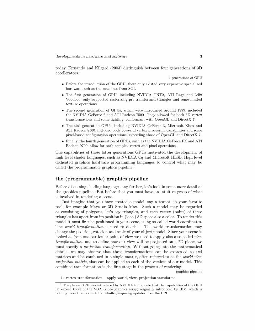
rendering of van Gogh painting with Impasto
4
example(s) – impasto
IMPaSTo2 is a realistic, interactive model for paint. It allows the user to createimages in the style of famous painters as in the example above, which is aftera painting of van Gogh. The impasto system implements a physical model ofpaint to simulate the effect of acrylic or oilpaint, using Cg shaders for real-timerendering, Baxter et al. (2004).
research directions – the art of shader programming
At first sight, shader programming seems to be an esoteric endeavor. However, asalready indicated in this section, there are a number of high level languages forshader programming, including NVIDIA Cg and Microsoft HLSL. Cg is a platformindependent language, suitable for both OpenGL and Direct3D. However, counterto what you might expect also Microsoft HLSL can be used for the OpenGLplatform when you choose the proper runtime support.
To support the development of shaders there are, apart from a number ofbooks, some powerful tools to write and test your shaders, in particular the alreadymentioned ATI Rendermonkey tool, the CgFx tool, which both produce HLSLcode, as well as the Cg viewer and the effect tool that comes with the MicrosoftDirectX 9 SDK.
Although I am only a beginning shader programmer myself, I find it trulyamazing what shaders can do. For a good introducion I advice Fernando andKilgard (2003). Futher you may consult Engel (2004a), Engel (2004b) and Engel(2005). Written from an artist’s perspective is St-Laurent (2004).
Stacks and stacks of books on DirectX5
2gamma.cs.unc.edu/IMPaSTo
DirectX 9 SDK 9
4.2 DirectX 9 SDKMany of the multimedia applications that you run on your PC, to play games,watch video, or browse through your photos, require some version of Direct X tobe installed. The most widely distributed version of Direct X is 7.0. The latestversion is the october release of 2004. This is version 9c. What is DirectX? And,more importantly, what can you do with it? In the DirectX documentation thatcomes with the SDK, we may read:
DirectX
Microsoft DirectX is an advanced suite of multimedia application program-ming interfaces (APIs) built into Microsoft Windows; operating systems.DirectX provides a standard development platform for Windows-based PCsby enabling software developers to access specialized hardware featureswithout having to write hardware-specific code. This technology was firstintroduced in 1995 and is a recognized standard for multimedia applicationdevelopment on the Windows platform.
Even if you don’t use the DirectX SDK yourself, and to do that you must be aquite versatile programmer, then you will find that the tools or plugins that youuse do depend on it. For example, the WildTangent3 game engine plugin makesthe DirectX 7 functionality available through both javascript and a Java interface.So understanding what DirectX has to offer may help you in understanding andexploiting the functionality of your favorite tool(s) and plugin(s).
DirectX 9.0 componentsIn contrast to OpenGL, the DirectX SDK is not only about (3D) graphics. Ineffect, it offers a wide range of software APIs and tools to assist the developer ofmultimedia applications. The components of the DirectX 9 SDK include:
DirectX 9 components
• Direct3D – for graphics, both 2D and 3D
• DirectInput – supporting a variety of input devices
• DirectPlay – for multiplayer networked games
• DirectSound – for high performance audio
• DirectMusic – to manipulate (non-linear) musical tracks
• DirectShow – for capture and playback of multimedia (video) streams
In addition there is an API for setting up these components. Also, DirectXsupports so-called media objects, which provide a standard interface to write audioand video encoders, decoders and effects.
Altogether, this is a truly impressive and complex collection of APIs. Oneway to become familiar with what the DirectX 9 SDK has to offer is to startup the sample browser that is part of the SDK and explore the demos. Anotherway is to read the online documentation that comes with the SDK, but perhaps a
3www.wildtangent.com
10 multimedia platforms
better way to learn is to make your choice from the large collection of introductorybooks, and start programming. At the end of this chapter, I will provide somehints about how to get on your way.
Direct3DIn the DirectX 9 SDK, Direct3D replaces the DirectDraw component of previousversions, providing a single API for all graphics programming. For Direct3Dthere is a set of simple, well-written tutorials in the online documentation, thatyou should start with to become familiar with the basics of graphics programmingin DirectX.
Direct3D tutorials
• tutorial 1: creating a device
• tutorial 2: rendering vertices
• tutorial 3: using matrices
• tutorial 4: creating and using lights
• tutorial 5: using texture maps
• tutorial 6: using meshes
Before you start working with the tutorial examples though, you should acquiresufficient skill in C++ programming4 and also some familiarity with MicrosoftVisual Studio .NET.
One of the most intricate (that means difficult) aspects of programming Di-rect3D, and not only for novices, is the creation and manipulation of what iscalled the device. It is advisable to take over the default settings from an example,and only start experimenting with more advanced setting after you gained someexperience.
DirectSound – the drumpad exampleThe DirectX SDK includes various utility libraries, for example the D3DX libraryfor Direct3D, to simplify DirectX programming.
As an example of a class that you may create with DirectSound, using such autility library, look at the drumpad below. The drumpad class can be integratedin your 3D program, using DirectInput, to create your own musical instrument.The header of the class, which is, with some syntactical modifications, taken fromthe SDK samples section, looks as follows:
4 The DirectX 9 SDK also offers APIs for C# and VisualBasic .NET. See the researchdirections at the end of this section.
DirectX 9 SDK 11
bool play( DWORD dwID );protected:
void CleanUp();CSoundManager* m lpSoundManager;CSound ** m lpSamples;
};
The interface offers some methods for creating and destroying a drumpad object,initialization, loading sounds and for playing the sounds that you loaded. TheCSoundManager is a class offered by the utility library for DirectSound.
The id parameter is a number that may be associated with for example a keyon your keyboard or some other input device. Using the drumpad class allowsyou to make your own VJ program, as I did in the system I will describe in thenext section. In case you are not familiar with either C++ or object-orientedprogramming, you should study object-oriented software development first. Seefor example Eliens (2000).
DirectShowDirectShow is perhaps the most powerful component of the DirectX SDK. It is thecomponent which made Mark Pesce remark that with the DirectX 9 SDK digitalconvergence has become a reality.5 A technical reality, that is, Pesce (2003).
As we have seen in chapter 3, working with multimedia presents some majorchallenges:
multimedia challenges
• volume – multimedia streams contain large amounts of data, which must beprocessed very quickly.
• synchronization – audio and video must be synchronized so that it starts and stopsat the same time, and plays at the same rate.
• delivery – data can come from many sources, including local files, computernetworks, television broadcasts, and video cameras.
• formats – data comes in a variety of formats, such as Audio-Video Interleaved(AVI), Advanced Streaming Format (ASF), Motion Picture Experts Group (MPEG),and Digital Video (DV).
5 It is historically interesting to note that Mark Pesce may be regarded as the inventor, orinitiator, of VRML, which was introduced in 1992 as the technology to realize a 3D web, asinterlinked collection of 3D spaces.
12 multimedia platforms
• devices – the programmer does not know in advance what hardware devices willbe present on the end-user’s system.
The DirectShow component was designed, as we learn from the online documenta-tion, to address these challenges and to simplify the task of creating applicationsby isolating applications from the complexities of data transports, hardware dif-ferences and synchronization. The solution DirectShow provides is a modulararchitecture that allows the developer to set up a data flow graph consisting offilters. Such filters may be used for capturing data from, for example, a videocamera or video file, for deploying a codec, through the audio compression man-ager (ACM) or video compression manager (VCM) interfaces, and for rendering,either to the file system or in the application using DirectSound and DirectDrawand Direct3D.
6
The diagram above, taken from the DirectX 9 SDK online documentation, showsthe relations between an application, the DirectShow components, and some ofthe hardware and software components that DirectShow supports.
An interesting and convenient feature of the filter-based dataflow architectureof DirectShow is SmartConnect, which allows the developer to combine filters byindicating constraints on media properties such as format. The actual connectionsthen, which involves linking input pins to output pins, is done automatically bysearching for the right order of filters, and possibly the introduction of auxiliaryfilters to make things match.
DepthCube, see example(s) – 3D vision
7
DirectX 9 SDK 13
DirectX application development
The examples that come with the DirectX‘9 SDK use an application utilitylibrary, which includes a general application class that takes care of most of thedetails of creating an application and rendering window, initialization and eventhandling. For each of the SDK components there are numerous examples, rangingin difficulty from beginners to expert level. There are also a number of examplesthat illustrate how to mix the functionality of different SDK components, as forexample the projection of video on 3D, which we will discuss in more detail in thenext section.
3D vision Perspectra DepthCube
8
example(s) – 3D vision
Have you ever wondered how it would feel to be in Star Trek’s holodeck, orexperience your game in a truly spatial way, instead of on a flat LCD-display.In Sullivan (2005), an overview is given of technology that is being developed toenable volumetric display of 3D data, in particular the Perspecta swept-volumedisplay (middle) and LightSpace DepthCube (right), that uses a projector behinda stack of 20 liquid-crystal screens.
The first approach of displaying volumetric data, taken by the Perspectaswept-volume display, is to project a sequence of images on a rotating sheetof reflective material to create the illusion of real volume. The psychologicalmechanism that enables us to see volumes in this way is the same as the mechanismthat forces us to see motion in frame-based animation, at 24 frames per second,namely persistence of vision.
LightSpace DepthCube uses a stack of 20 transparent screens and alternatesbetween these screens in a rapid way, thus creating the illusion of depth in asimilar way. In comparison with other approaches of creating depth illusion, thesolutions sketched above require no special eyewear and do not impose any strainon the spectator due to unnatural focussing as for example with autostereoscopicdisplays.
For rendering 3D images on either the Perspecta or DepthCube traditionalrendering with for example OpenGL suffices, where the z-coordinate is taken asan indication for selecting a screen or depth position on the display. Renderingwith depth, however, comes at a price. Where traditional rendering has to deal
14 multimedia platforms
with, say 1024x748 pixels, the DepthCube for example needs to be able to display1024x748x20, that is 15.3 million, voxels (the volumetric equivalent of a pixel) ata comparable framerate.
research directions– the next generation multimedia platform
Factors that may influence your choice of multimedia development platform in-clude:
• platform-dependence – both hardware and OS
• programming language – C/C++, Java, .NET languages
• functionality – graphics, streaming media
• deployment – PC/PDA, local or networked, web deployment
A first dividing line is whether you prefer to develop on/for Linux or Microsoftwindows. Another dividing line, indeed, is your choice of programming language,C/C++, Java or .NET languages. Another factor that may influence your choiceis the functionality you strive for. For example, Managed DirectX, for the .NETlanguages, provides only limited support for DirectShow and does not allow forcapturing live video from a DV camera. And finally, it matters what deploymentyou wish to target for, mobile phone, PDAs or PCs, and whether you plan tomake stand-alone applications or applications that must run in a web browser.
Apart from the hard-core programming environments such as the MicrosoftDirectX 9 SDK, the Java Media Framework, OpenGL with OpenML extensionsfor streaming media, or the various open source (game development) toolkits,there are also high-level tools/environments, such as Macromedia Director MX,that allow you to create similar functionality with generally less effort, but alsoless control. In appendix E, a number of resources are listed that may assist youin determining your choice.
Given the range of possible options it is futile to speculate on what the futurewill offer. Nevertheless, whatever your choice is, it is good to keep in mind,quoting Bill Gates:
Software will be the single most important force in digital entertainment overthe next decade.
It should not come as a surprise that this statement is meant to promote a newinitiative, XNA, which as the announcement says is targeted to help contain theskyrocketing development costs and allow developers to concentrate on the uniquecontent that differentiates their games.
merging video and 3D 15
Animation in front of television news in ViP9
4.3 merging video and 3D
In june 2003, I was approached by a theatre production company to advice on theuse of "VR in theatre". As described in more detail in section 9.3, I exploredwhat technology was available to realize such VR-augmented theatre. Theseexplorations resulted in the development of the ViP system, that I once announcedas follows:
www.virtualpoetry.tv
The ViP system enhances your party with innovative multimedia presenta-tions.
It supports multiple webcams and digital video cameras, mixed with videoand images, enhanced by 3D animations and text, in an integrated fashion.
For your party, we create a ViP presentation, with your content and specialeffects, to entertain your audience.
In the course of time, I continued working on the system and, although I do notuse it for parties, but rather for enlivening my lectures, it does include many ofthe features of a VJ system, such as the drumpad described in 3.2.
The major challenge, when I started its development, was to find an effectiveway to map live video from a low/medium resolution camera as textures onto3D geometry. I started with looking at the ARToolkit but I was at the time notsatisfied with its frame rate. Then, after some first explorations, I discoveredthat mapping video on 3D was a new (to some extent still experimental) built-infeature of the DirectX 9 SDK, in the form of the VMR9 (video mixing renderer)filter.
the Video Mixing Renderer filter
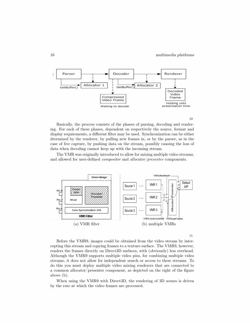
The VMR filter is a compound class that handles connections, mixing, composit-ing, as well as synchronization and presentation in an integrated fashion. Butbefore discussing the VMR9 in more detail, let’s look first at how a single mediastream is processed by the filter graph, as depicted in the figure below.
16 multimedia platforms
10
Basically, the process consists of the phases of parsing, decoding and render-ing. For each of these phases, dependent on respectively the source, format anddisplay requirements, a different filter may be used. Synchronization can be eitherdtermined by the renderer, by pulling new frames in, or by the parser, as in thecase of live capture, by pushing data on the stream, possibly causing the loss ofdata when decoding cannot keep up with the incoming stream.
The VMR was originally introduced to allow for mixing multiple video streams,and allowed for user-defined compositor and allocator/presenter components.
(a) VMR filter (b) multiple VMRs
11
Before the VMR9, images could be obtained from the video stream by inter-cepting this stream and copying frames to a texture surface. The VMR9, however,renders the frames directly on Direct3D surfaces, with (obviously) less overhead.Although the VMR9 supports multiple video pins, for combining multiple videostreams, it does not allow for independent search or access to these streams. Todo this you must deploy multiple video mixing renderers that are connected toa common allocator/presenter component, as depicted on the right of the figureabove (b).
When using the VMR9 with Direct3D, the rendering of 3D scenes is drivenby the rate at which the video frames are processed.
merging video and 3D 17
Lecture on digital dossier for Abramovic, in ViP12
the ViP system
In developing the ViP system, I proceeded from the requirement to project livevideo capture in 3D space. As noted previously, this means that incoming videodrives the rendering of 3D scenes and that, hence, capture speed determines therendering frame rate.
I started with adapting the simple allocator/presenter example from the Di-rectX 9 SDK, and developed a scene management system that could handleincoming textures from the video stream. The scene class interface, which allowsfor (one-time) initialization, time-dependent compositing, restore device settingand rendering textures, looks as follows:
class scene {public:
virtual int init(IDirect3DDevice9*); // initialize scene (once)virtual int compose(float time); // compose (in the case of an
animation)virtual int restore(IDirect3DDevice9*); // restore device settingsvirtual int render(IDirect3DDevice9* device, IDirect3DTexture9*
texture);protected:...};
The scene graph itself was constructed as a tree, using both arrays of (sub) scenesas well as a dictionary for named scenes, which is traversed each time a videotexture comes in. The requirements the scene management system had to satisfyare further indicated in section 9.3. Leaving further details aside, observe thatfor the simple case of one incoming video stream, transferring the texture byparameter suffices.
Later on, I adapted the GamePlayer which uses multiple video mixing ren-deres, and then the need arose to use a different way of indexing and accessing thetextures from the video stream(s). So, since it is good practice in object-oriented
18 multimedia platforms
software engineering to suppress parameters by using object instance variables,the interface for the scene class changed into:
class scene {public:
virtual int load(); // initialize scene (once)virtual int compose(); // compose (in the case of an animation)virtual int restore(); // restore device settingsvirtual int render(); // display the (sub) scene
protected:...};
Adopting the scene class as the unifying interface for all 3D objects and compoundscenes proved to be a convenient way to control the complexity of the ViPapplication. However, for manipulating the textures and allocating shader effectsto scenes, I needed a global data structure (dictionaries) to access these itemsby name, whenever needed. As a final remark, which is actually more concernedwith the software engineering of such systems that its functionality per se, to beable to deal with the multiple variant libraries that existed in the various releasesof DirectX 9, it was needed to develop the ViP library and its components as acollection of DLLs, to avoid the name and linking clashes that would otherwiseoccur.
installation reality of TV news
13
example(s) – reality of TV newsThe Reality of TV news project by Peter Frucht uses an interesting mix oftechnology:
• live video capture from the device of an external USB2.0 TV card
• live audio capture from the soundcard (line in)
• display of live audio and video with java3D (had to be invented)
• autonomous 3D objects with a specified lifetime
merging video and 3D 19
• collision behaviour (had to be invented)
• changing of texture-, material- and sound characteristics at runtime
• dual-screen display with each screen rotated toward the other by 45 degrees aboutthe Y-axis
• 3D sound
In the project, as phrased by Peter Frucht, the permanent flow of the alternat-ing adverts and news reports are captured live and displayed in a 3D virtual-realityinstallation. The currently captured audio and video data is displayed on thesurface of 3D shapes as short loops. The stream enters the 3D universe pieceby piece (like water drops), in this way it is getting displaced in time and space -news reports and advertising will be displayed partly in the same time. By collidingto each other the 3D shapes exchange video material. This re-editing mixes theshort loops together, for instance some pieces of advertising will appear while thenewsreader speaks.
The software was developed by Martin Bouma, Anthony Augustin and Pe-ter Frucht himself, with jdk 1.5, java3d 1.31, Java Media Framework 2.1.1e.The primary technological background of the artist, Peter Frucht, was the bookCodeArt6, Trogemann & Viehoff (2004), by his former professor from the MediaArt School in Cologne, Germany. The book is unfortunately only available inGerman, and should be translated in English!
research directions– augmented reality
In the theatre production that motivated the development of the ViP system,the idea was to have wearable LCD-projection glasses, with a head-mounted lowresolution camera. This setup is common in augmented reality applications, wherefor example a historic site is enriched with graphics and text, laid on top of the(video rendered) view of the site. Since realtime image analysis is generallynot feasible, either positioning and orientation information must be used, orsimplified markers indicating the significant spots in the scene, to determine whatinformation to use as an overlay and how it should be displayed.
The ARToolkit7 is an advanced, freely available, toolkit, that uses fast markerrecognition to determine the viewpoint of a spectator. The information that isreturned on the recognition of a marker includes both position and orientation,which may be used by the application to draw the overlay graphics in accordancewith the spectator’s viewpoint.
Augnented reality is likely to become a hot thing. In april 2005 it was featuredat BBC World8, with a tour through Basel.
The title of this section is borrowed from a lecture given for the VU computerscience student association (STORM9), indeed, entitled gaming is a waste of time.This admittedly provocative title was on the one hand meant to emphasize thenotion waste of time, since according to some of my collegue staff members myinvolvement in game development and multimedia technology was a mere wasteof time, from some (from my point of view) obscure academic perspective. Onthe other hand, it (that is the title) also raised a more serious issue. Not being agame player myself, I do (in some sense) consider game playing a waste of time.Not that I deny the learning or entertainment aspects of games. On the contrary!Yes, as a passing of time, I prefer to keep myself busy with the construction ofgames, that is the creative and technological aspects of game development. And,likewise, I advise my students to do so.
When I was asked, in an alumni interview with the magazine of CWI10,whether I believed in Second Life, my answr was simply: I believe in nothing!I take Second Life as an object of study, not in the last place because it hasrecently become so surprisingly popular. Yet, to be fair, Second Life has, aftercloser inspection, also technological merits of its own right.
In Eliens et al. (2007), we wrote: from a technical perspective, Second Lifeoffers an advanced game engine that visitors and builders use (implicitly) intheir activities. For essential components of game engine(s), we refer to section11.1. In the following table, we give a brief comparative technical overview of,respectively, the Blaxxun Community Server (BlC), AlphaWorld (AW), the opensource Delta3D engine (D3D), the Half Life 2 Source SDK (HL2), and SecondLife (SL).
Obviously, open source engines allow for optimal extensibility, and in this respectthe open source version of the SL client may offer many opportunities. Strong
9www.storm.vu.nl10www.cwi.nl
development(s) – gaming is a waste of time 21
points of SL appear to be in-game building, avatar manipulation, and in compari-son with BlC and AW built-in physics and object collision detection. Weak pointsappear to be content development tool support, and especially in comparison withD3D and HL2 interaction. For most types of action-game like interaction SL issimply too slow. This even holds for script-driven animations, as we will discussin the next section. In comparison with a game as for example Age of EmpiresIII11, which offers in-game building and collaboration, Second Life distinguishesitself by providing a 3D immersive physics-driven environment, like the ’real’ gameengines.
Although we do not intend to realize Clima Futura in Second Life, we actuallyuse flash to reach an audience as wide as possible, as a pilot parts of the gamecould fruitfully be realized in the VU virtual campus in Second Life, in particularthe search for knowlegde, that is looking for an expert in a particular area of(climate-related) research. A similar quest was implemented in our Half Life 2based game VULife, Eliens and Bhikharie (2006), where the player had to visitnine information spots, which resulted in displaying in a HUD nine square matrixthe location of a hidden treasure, which was then actually the power to use arms.Technical issues in realizing Clima Futura in Second Life are support for ranking,as well as meta-information with respect to locations where relevant informationcan be found, which may be realized with the techniques indicated in section 2.4.
In the beginning, we wrote in Eliens et al. (2007b), we envisioned the realiza-tion of our climate game as a first-person perspective role-playing game in a 3Dimmersive environment as for example supported by the Half Life 2 SDK, withwhich we gained experience in creating a search the hidden treasure12 game ina detailed 3D virtual replica of our faculty. However, we soon realized that theuse of such a development platform, would require far too much work, given thecomplexity of our design. So, instead of totally giving up on immersion, we decidedto use flash video13, indeed as a poor-man’s substitute for real 3D immersion,which, using flash14 interactive animations, has as an additional benefit thatit can be used to play games online, in a web browser. Together with theFlex 2 SDK15, which recently became open source, flash offers a rich internetapplication (RIA) toolkit, that is sufficiently versatile for creating (online) games,that require, in relation to console games or highly realistic narrative games likeHalf Life, a comparatively moderate development effort. To allow for component-wise development, we choose for a modular architecture, with four basic modulesand three (variants) of integration modules, as indicated below.
1. climate model(s) - action script module(s)2. game play interaction - event-handler per game event3. video content module - video fragment(s) and interaction overlays4. minigame(s) - flash module(s) with actionscript interface5. Clima Futura - integration of modules 1-4, plus server-side ranking6. adapted versions – educational, commercial7. multi-user version –with server-side support
In addition, we would like to develop a facility that allows players not onlysubmit their own video material, but also to build or modify their own minigames,which might then be included in the collection of mini-games provided by ClimaFutura. This, however, requires apart from a participatory (web 2.0) web-site, anappropriate game-description format, which we will discuss in section 11.4.
collada – gluing it all togetherThe wide variety of formats and tools for content production has been a stumblingblock for many projects. How to find a unified format for digital content creation(DCC), so that content may be easily reused across projects and tools? Apromising attempt in this direction is the collada initiative, Arnaud & Barnes(2006). The standard proposed in Arnaud & Barnes (2006) is meant to serve asan intermediate or interchange format for interactive (multimedia) applications,such as games, which can be characterized as:
Interactive multimedia applications have as a common property that, in contrastfor example to computer graphics (CG) movies, everything must be available,that is computed, in real time. The intermediate format (collada), presentedin Arnaud & Barnes (2006), is an XML-encoding of the various elements thatmay result from the content pipeline, that is the workflow of (digital) contentcreation, of a (multimedia) project, including:
The list above gives an indication of what (description) primitives the colladastandard offers, to facilitate the exchange of (content) information and to promotere-use across tools and platforms.
14
questionsmultimedia platforms
1. What components does a multimedia platform consist of? Discuss both hardwareand software components.
concepts
2. Characterize the functionality of current multimedia platforms.
3. Explain the notions of vertex shader and pixel shader.
4. Indicate what solutions exist for merging video and 3D graphics.technology
5. Characterize the capabilty of current GPUs.
6. What does HLSL stand for? Give some examples of what it is used for.
7. What are the components of the DirectX 9 SDK?
8. Explain how the VMR9 works. Give an example.
projects & further reading As a project, I suggest the development of shaderprograms using Rendermonkey17 or the Cg Toolkit18, or a simple game in DirectX.
You may further explore the possibilities of platform independent integrationof 3D and media, by studying for example OpenML19. For further reading, amongthe many books about DirectX, I advice Luna (2003), Adams (2003) and Fay etal. (2004).
the artwork17www.ati.com/developer/RenderMOnkey18www.nvidia.com/cg19www.khronos.org/openml
24 multimedia platforms
1. dutch light – photographs from documentary film Dutch Light20.
2. ViP – screenshot, with morphing shader, see section 4.3.
3. impasto – examples, see section 4.1
4. impasto – after a painting of van Gogh, using Cg shaders,
5. 3D vision, from Sullivan (2005), see example(s) section 4.2.
6. idem.
7. photographs of DirectX and multimedia books, by the author.
8. DirectX – diagram from online documentation.
9. ViP – screenshot, with the news and animations.
10. DirectX – diagram from online documentation.
11. DirectX – diagram from online documentation.
12. ViP – screenshot, featuring Abramovic.
13. Peter Frucht – Reality of TV news, see section 4.3.
14. Clima Futura – architecture diagram.
15. signs – people, van Rooijen (2003), p. 248, 249.
The theme of the artwork of this chapter is realism. In the documentary dutchlight, it was investigated whether the famous dutch light in 17th century paintingreally existed. The photographs shown here are a selection of shots that weretaken on particular locations over a period of time. However, as an art historianformulated it in the documentary: dutch light is nothing but a bag of tricks sharedby dutch 17th century painters. The examples from impasto demonstrated that,after all, realism is an arbitrary notion.