73
4: Network Layer 4a-1 15: Inter and intra AS, RIP, OSPF, BGP, Router Architecture Last Modified: 03/22/22 04:56 PM
| Date post: | 02-Jan-2016 |
| Category: |
Documents |
| Upload: | muriel-gilmore |
| View: | 218 times |
| Download: | 0 times |

4: Network Layer 4a-1
15: Inter and intra AS, RIP, OSPF, BGP, Router Architecture
Last Modified: 04/20/23 12:59 AM

4: Network Layer 4a-2
Recall CIDR
“Send me anythingwith addresses beginning 200.23.16.0/20”
200.23.16.0/23
200.23.18.0/23
200.23.30.0/23
Fly-By-Night-ISP
Organization 0
Organization 7Internet
Organization 1
ISPs-R-Us“Send me anythingwith addresses beginning 199.31.0.0/16”
200.23.20.0/23Organization 2
...
...
We already talked about how routing based on hierarchical allocation of IP address space can allows efficient advertisement of routing information:

4: Network Layer 4a-3
CIDR? Dynamic Routing?
CIDR by itself is a nice idea but.. Hard to maintain Work around existing IP address space
allocations What about redundant paths?
Dynamic routing protocols? They maintain/update themselves Allow for redundant paths But could every router in the Internet be a
node in the graph?

4: Network Layer 4a-4
Dynamic Routing Protocols?
scale: with 200 million destinations: can’t store all destinations in routing tables! routing table exchange would swamp links! Neither link state nor distance vector could
handle the whole Internet!
Our study of dynamic routing protocols thus far = idealized graph problem
all routers identical network “flat”… not true in practice

4: Network Layer 4a-5
Routing in the Internet
Administrative Autonomy Internet = network of networks Each network controls routing in its own network
Global routing system to route between Autonomous Systems (AS) Autonomous System is a connected group of IP networks
that adhere to a single unique routing policy that differs from the routing policies of its network's border peers.
Two-level routing/hierarchical routing: Intra-AS: administrator is responsible for choice Inter-AS: unique standard
4: Network Layer 4a-6
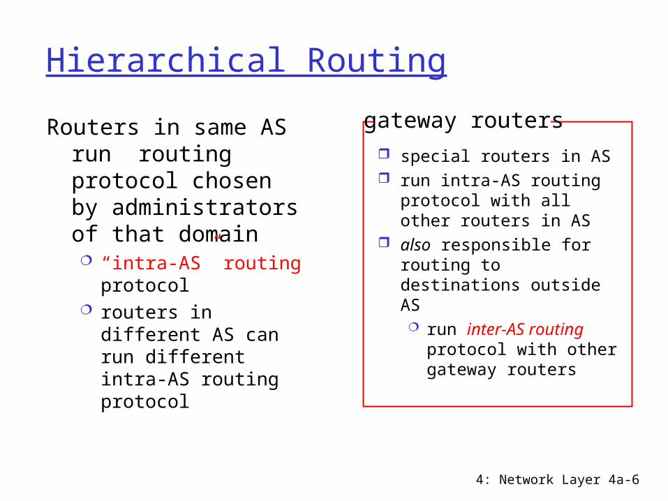
Hierarchical Routing
Routers in same AS run routing protocol chosen by administrators of that domain “intra-AS” routing
protocol routers in different AS
can run different intra-AS routing protocol
special routers in AS run intra-AS routing
protocol with all other routers in AS
also responsible for routing to destinations outside AS run inter-AS routing
protocol with other gateway routers
gateway routers

4: Network Layer 4a-7
Internet AS HierarchyInter-AS border (exterior gateway) routers
Intra-AS interior (gateway) routers

4: Network Layer 4a-8
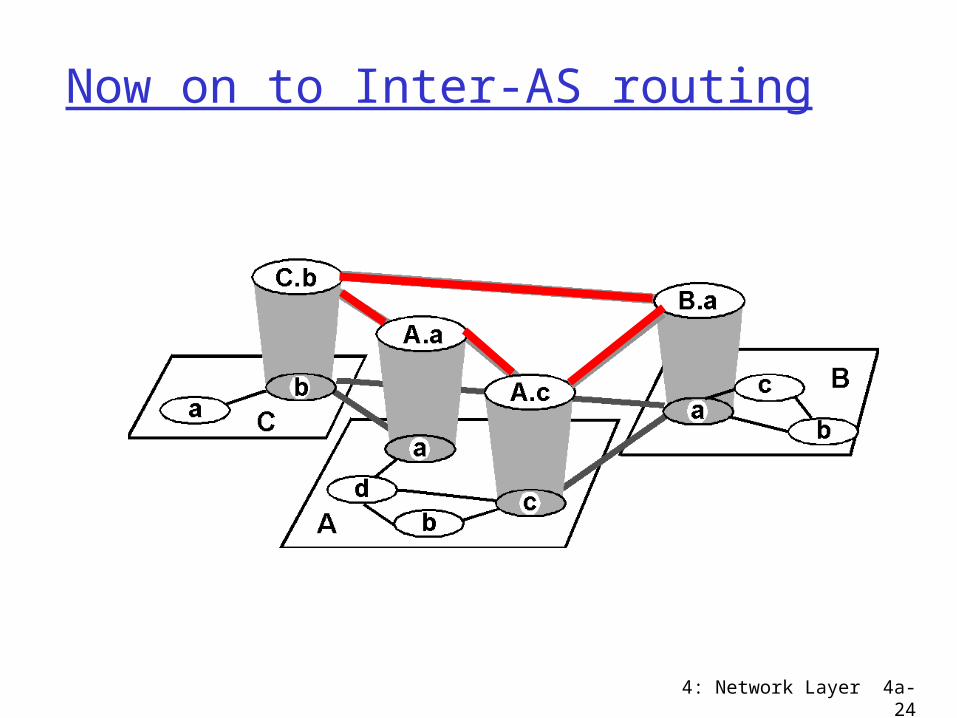
Intra-AS and Inter-AS routing
Gateways:•perform inter-AS routing amongst themselves•perform intra-AS routers with other routers in their AS
inter-AS, intra-AS routing in
gateway A.c
network layer
link layer
physical layer
a
b
b
aaC
A
Bd
A.a
A.c
C.bB.a
cb
c

4: Network Layer 4a-9
Intra-AS and Inter-AS routing
Host h2
a
b
b
aaC
A
Bd c
A.a
A.c
C.bB.a
cb
Hosth1
Intra-AS routingwithin AS A
Inter-AS routingbetween A and B
Intra-AS routingwithin AS B
Single datagram is often routed over many hops via routes established by several intra-AS routing protocols and an inter-AS routing protocol

4: Network Layer 4a-10
Intra vs Inter AS Routing protcols For Intra AS routing protocols: many choices;
For Inter AS routing protocols: standard Why does this make sense?
Intra AS routing protocols focus on performance optimization; Inter AS routing protocols focus on administrative issues Why does this make sense?
Choice in Intra-AS Intra-AS often static routing based on CIDR, can also
be dynamic (usually RIP or OSPF)
Standard Inter-AS BGP is dynamic
4: Network Layer 4a-11
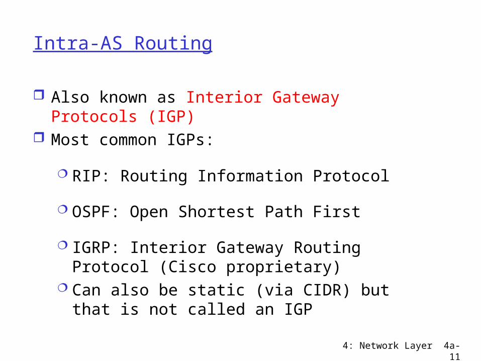
Intra-AS Routing
Also known as Interior Gateway Protocols (IGP) Most common IGPs:
RIP: Routing Information Protocol
OSPF: Open Shortest Path First
IGRP: Interior Gateway Routing Protocol (Cisco proprietary)
Can also be static (via CIDR) but that is not called an IGP

4: Network Layer 4a-12
RIP ( Routing Information Protocol)
Distance vector algorithm Included in BSD-UNIX Distribution in 1982 Single Distance metric: # of hops (max = 15 hops)
Can you guess why? Count to infinity less painful if infinity = 16 But limits RIP to networks with a diameter of 15 hops
Distance vectors: exchanged every 30 sec via Response Message (also called advertisement)
Each advertisement: route to up to 25 destination nets
Each link has cost 1

4: Network Layer 4a-13

4: Network Layer 4a-14
RIP: Link Failure and Recovery If no advertisement heard after 180 sec -->
neighbor/link declared dead routes via neighbor invalidated new advertisements sent to neighbors neighbors in turn send out new advertisements
(if tables changed) link failure info quickly propagates to entire net poison reverse used to prevent small loops infinite distance = 16 hops to make make
problem with larger loops less painful

4: Network Layer 4a-15
RIP Table processing
RIP routing tables managed by application-level process called route-d (daemon)
advertisements sent in UDP packets, periodically repeated
Periodically inform kernel of routing table to use
Network Layer 4-16
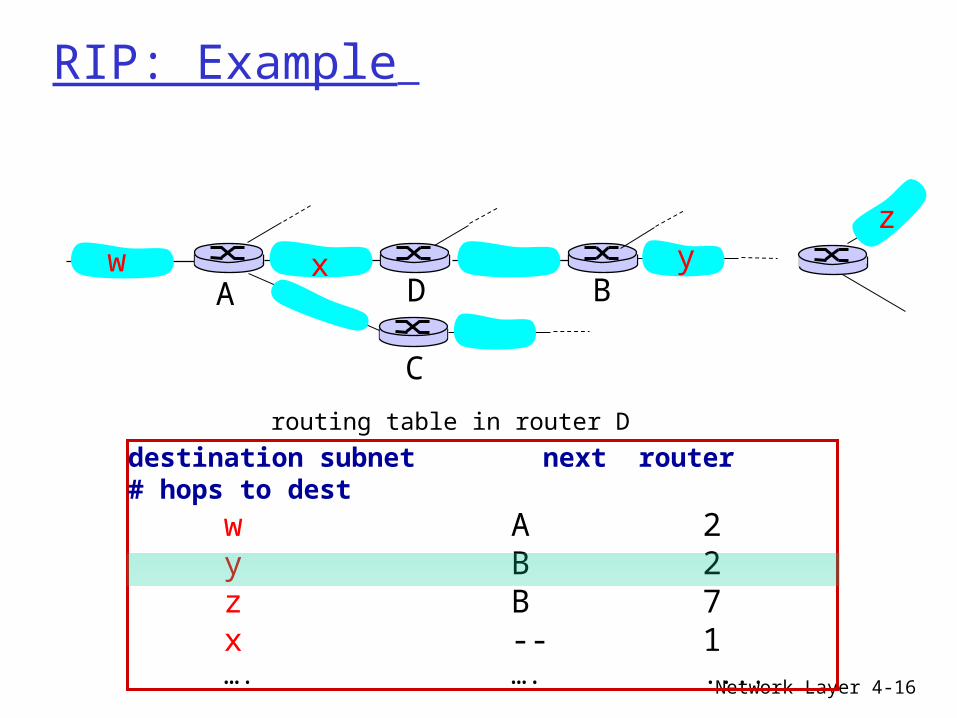
RIP: Example
destination subnet next router # hops to dest
w A 2y B 2
z B 7x -- 1…. …. ....
routing table in router D
w x yz
A
C
D B

Network Layer 4-17
RIP: Example
destination subnet next router # hops to dest
w A 2y B 2
z B 7x -- 1…. …. ....
routing table in router D
w x yz
A
C
D B
A 5
dest next hops w - 1 x - 1 z C 4 …. … ...
A-to-D advertisement

4: Network Layer 4a-18
OSPF (Open Shortest Path First)
“open”: publicly available Uses Link State algorithm
LS packet dissemination Topology map at each node Route computation using Dijkstra’s algorithm
OSPF advertisement carries one entry per neighbor router (i.e. cost to each neighbor)
Advertisements disseminated to entire AS (via flooding) carried in OSPF messages directly over IP (rather than
TCP or UDP

4: Network Layer 4a-19

4: Network Layer 4a-20
OSPF “advanced” features (not in RIP)
Many have nothing to do with link-state vs distance vector!!
Security: all OSPF messages authenticated (to prevent malicious intrusion); TCP connections used
Multiple same-cost paths can be used at once (single path need not be chosen as in RIP)
For each link, multiple cost metrics for different TOS (eg, high BW, high delay satellite link cost may set “low” for best effort; high for real time)
Integrated uni- and multicast support: Multicast OSPF (MOSPF) uses same topology data base as
OSPF Hierarchical OSPF in large domains
Full broadcast in each sub domain only

4: Network Layer 4a-21
Hierarchical OSPF: Mini Internet
Within each area, border routerresponsible for routing outside the area
Exactly one area is backbone area
Backbone area contains all area border routers and possibly others

4: Network Layer 4a-22
Hierarchical OSPF
Two-level hierarchy: local area, backbone. Link-state advertisements only in area each nodes has detailed area topology; only know
direction (shortest path) to nets in other areas. Area border routers: “summarize” distances to
nets in own area, advertise to other Area Border routers.
Backbone routers: run OSPF routing limited to backbone.
Boundary routers: connect to other ASs.
4: Network Layer 4a-23
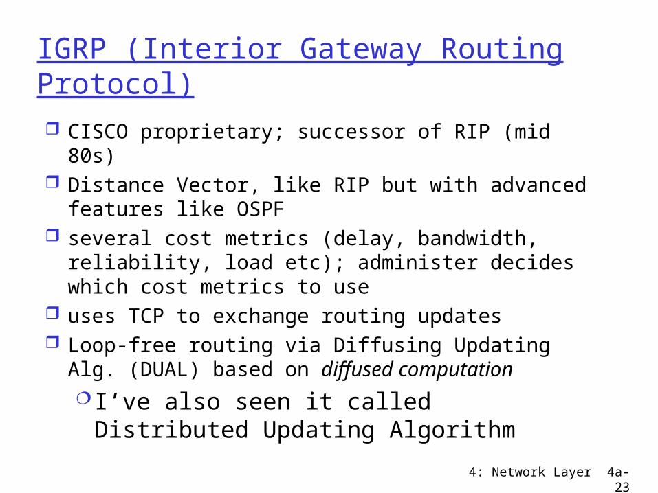
IGRP (Interior Gateway Routing Protocol) CISCO proprietary; successor of RIP (mid 80s) Distance Vector, like RIP but with advanced
features like OSPF several cost metrics (delay, bandwidth,
reliability, load etc); administer decides which cost metrics to use
uses TCP to exchange routing updates Loop-free routing via Diffusing Updating Alg.
(DUAL) based on diffused computation I’ve also seen it called Distributed
Updating Algorithm
4: Network Layer 4a-24
Now on to Inter-AS routing

4: Network Layer 4a-25
Autonomous systems
The Global Internet consists of Autonomous Systems (AS) interconnected with each other: Stub AS: small corporation Multihomed AS: large corporation (no transit
traffic) Transit AS: provider (carries transit traffic)
Major goal of Inter-AS routing protocol is to reduce transit traffic
Every AS needs an globally unique AS number of ASN
Handed out by regional registries An ASN enables an AS to exchange
exterior routing information with neighboring ASes.
4: Network Layer 4a-26

4: Network Layer 4a-27
Internet inter-AS routing: BGP
BGP (Border Gateway Protocol): the de facto standard
Path Vector protocol: similar to Distance Vector protocol Avoids count-to-infinity problem by
identifying yourself in a path advertised to you
each Border Gateway broadcast to neighbors (peers) entire path (I.e, sequence of ASNs) to destination
E.g., Gateway X may send its path to dest. Z:
Path (X,Z) = X,Y1,Y2,Y3,…,Z

4: Network Layer 4a-28
Internet inter-AS routing: BGP
Path Vector protocol: similar to Distance Vector protocol Avoids count-to-infinity problem by
identifying yourself in a path advertised to you
each Border Gateway broadcast to neighbors (peers) entire path (I.e, sequence of ASNs) to destination
E.g., Gateway X may send its path to dest. Z:
Path (X,Z) = X,Y1,Y2,Y3,…,Z

Network Layer 4-29
BGP basics
when AS3 advertises a prefix to AS1: AS3 promises it will forward datagrams towards that prefix AS3 can aggregate prefixes in its advertisement
AS3
AS2
3b
3c
3a
AS1
1c1a
1d1b
2a2c
2b
othernetworks
othernetworks
BGP session: two BGP routers (“peers”) exchange BGP messages: advertising paths to different destination network prefixes
(“path vector” protocol) exchanged over semi-permanent TCP connections
BGP message
Network Layer 4-30
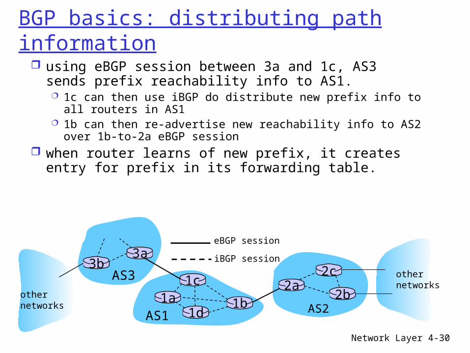
BGP basics: distributing path information
AS3
AS2
3b3a
AS1
1c1a
1d1b
2a2c
2b
othernetworks
othernetworks
using eBGP session between 3a and 1c, AS3 sends prefix reachability info to AS1. 1c can then use iBGP do distribute new prefix info to all
routers in AS1 1b can then re-advertise new reachability info to AS2 over
1b-to-2a eBGP session when router learns of new prefix, it creates entry for
prefix in its forwarding table.
eBGP session
iBGP session

Network Layer 4-31
Path attributes & BGP routes
advertised prefix includes BGP attributes prefix + attributes = “route”
two important attributes: AS-PATH: contains ASs through which prefix
advertisement has passed: e.g., AS 67, AS 17 NEXT-HOP: indicates specific internal-AS router to next-
hop AS. (may be multiple links from current AS to next-hop-AS)
gateway router receiving route advertisement uses import policy to accept/decline e.g., never route through AS x policy-based routing

4: Network Layer 4a-32
Internet inter-AS routing: BGP
Suppose: gateway X send its path to peer gateway W W may or may not select path offered by X
cost, policy (don’t route via competitors AS!), loop prevention reasons.
If W selects path advertised by X, then:Path (W,Z) = w, Path (X,Z)
Note: X can control incoming traffic by controlling its route advertisements to peers: e.g., don’t want to route traffic to Z -> don’t advertise any routes
to Z
Network Layer 4-33
BGP route selection
router may learn about more than 1 route to destination AS, selects route based on:
1. local preference value attribute: policy decision
2. shortest AS-PATH 3. closest NEXT-HOP router: hot potato
routing4. additional criteria
4: Network Layer 4a-34
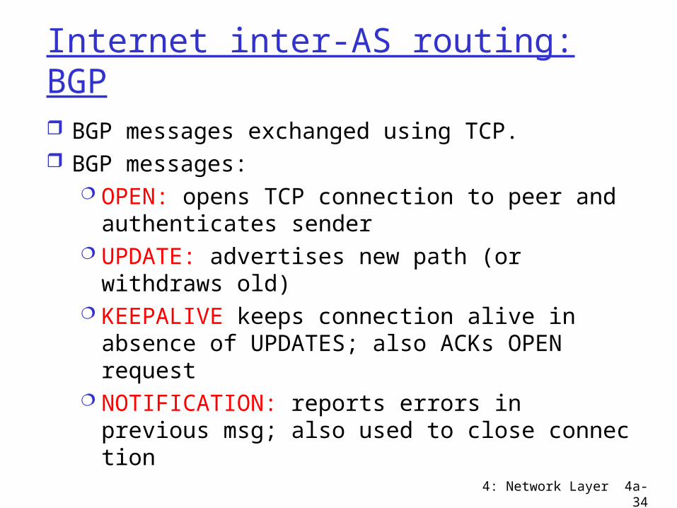
Internet inter-AS routing: BGP
BGP messages exchanged using TCP. BGP messages:
OPEN: opens TCP connection to peer and authenticates sender
UPDATE: advertises new path (or withdraws old)
KEEPALIVE keeps connection alive in absence of UPDATES; also ACKs OPEN request
NOTIFICATION: reports errors in previous msg; also used to close connec tion
Network Layer 4-35
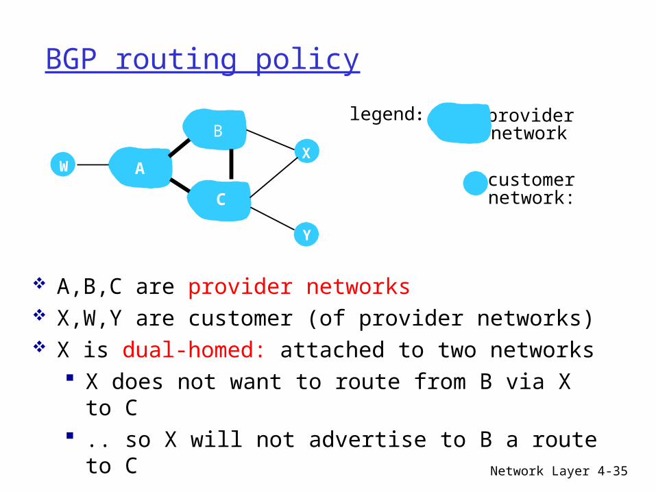
BGP routing policy
A,B,C are provider networks X,W,Y are customer (of provider networks) X is dual-homed: attached to two networks
X does not want to route from B via X to C .. so X will not advertise to B a route to C
A
B
C
W X
Y
legend:
customer network:
provider network

Network Layer 4-36
BGP routing policy (2)
A advertises path AW to B B advertises path BAW to X Should B advertise path BAW to C?
No way! B gets no “revenue” for routing CBAW since neither W nor C are B’s customers
B wants to force C to route to w via A B wants to route only to/from its customers!
A
B
C
W X
Y
legend:
customer network:
provider network

4: Network Layer 4a-37

Network Layer 4-38
Why different Intra- and Inter-AS routing ?
Policy: Inter-AS: admin wants control over how its traffic
routed, who routes through its net. Intra-AS: single admin, so no policy decisions
needed
Scale: hierarchical routing saves table size, reduced
update trafficPerformance: Intra-AS: can focus on performance Inter-AS: policy may dominate over performance

4: Network Layer 4a-39
Internet Map
Now that we know about autonomous systems and intra and inter AS routing protocols
What does the Internet really look like? That is a actually a hard question to answer Internet Atlas Project
• http://www.caida.org/projects/internetatlas/• Techniques, software, and protocols for mapping
the Internet, focusing on Internet topology, performance, workload, and routing data

4: Network Layer 4a-40
The Internet around 1990
4: Network Layer 4a-41
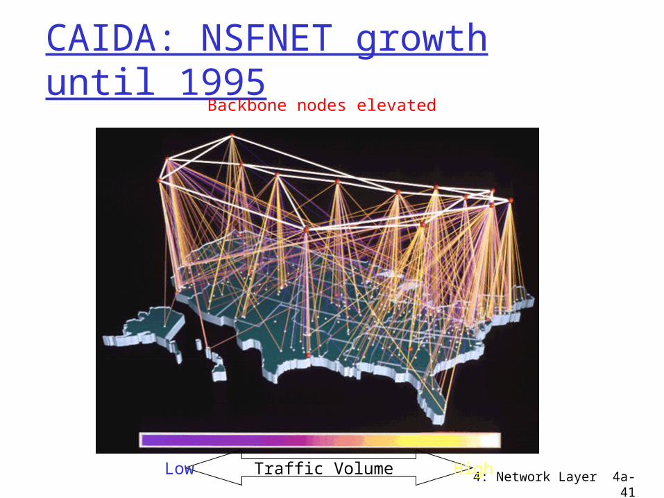
CAIDA: NSFNET growth until 1995
Backbone nodes elevated
Low Traffic Volume High

4: Network Layer 4a-42
NSF Networking Architecture of Late 1990s NSFNET Backbone Project successfully
transitioned to a new networking architecture in 1995. vBNS ( very high speed Backbone Network
Services) - NSF funded, provided by MCI 4 original Network Access Points (NSF
awarded) NSF funded Routing Arbiter project Network Service Providers (not NSF funded)

4: Network Layer 4a-43
Network Access Point
Allows Internet Service Providers (ISPs), government, research, and educational organizations to interconnect and exchange information
ISPs connect their networks to the NAP for the purpose of exchanging traffic with other ISPs
Such exchange of Internet traffic is often referred to as "peering"

4: Network Layer 4a-44
The Internet in 1997
4: Network Layer 4a-45
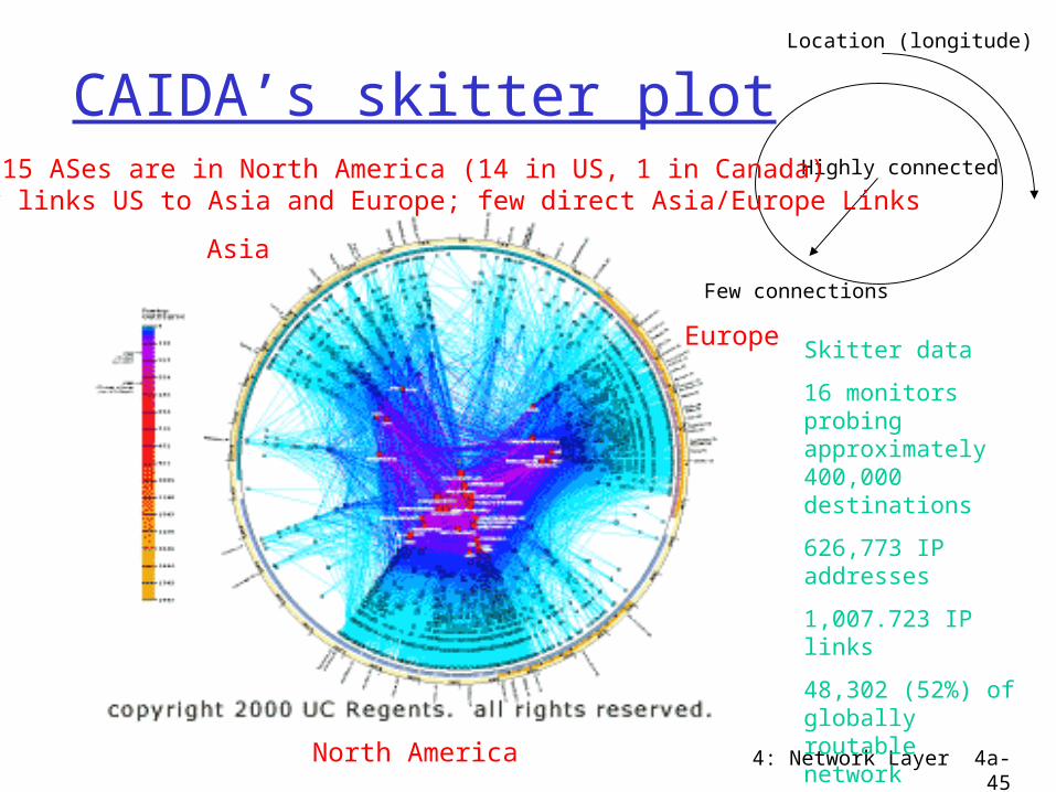
CAIDA’s skitter plotHighly connected
Few connections
Location (longitude)
Skitter data
16 monitors probing approximately 400,000 destinations
626,773 IP addresses
1,007.723 IP links
48,302 (52%) of globally routable network prefixes
Europe
North America
Asia
Top 15 ASes are in North America (14 in US, 1 in Canada)Many links US to Asia and Europe; few direct Asia/Europe Links

4: Network Layer 4a-46
Economics of Internet Connectivity Upstream ISPs charge downstream ISPs
for connectivity (transit traffic) Downstream ISPs change customers Upper level ISPs exchange traffic at
NAPs for mutual convenience

4: Network Layer 4a-47
Roadmap
Mechanics of Routing Sending datagram to destination on same
network Sending datagram to destination on a
different network Router Architecture Router Configuration Demo

4: Network Layer 4a-48
Getting a datagram from source to dest.
IP datagram:
223.1.1.1
223.1.1.2
223.1.1.3
223.1.1.4 223.1.2.9
223.1.2.2
223.1.2.1
223.1.3.2223.1.3.1
223.1.3.27
A
BE
miscfields
sourceIP addr
destIP addr data
Most of datagram remains unchanged, as it travels source to destination
addr fields of interest here
Dest. Net. next router Nhops
223.1.1 1223.1.2 223.1.1.4 2223.1.3 223.1.1.4 2
routing table in A

4: Network Layer 4a-49
Destination on same network as source
223.1.1.1
223.1.1.2
223.1.1.3
223.1.1.4 223.1.2.9
223.1.2.2
223.1.2.1
223.1.3.2223.1.3.1
223.1.3.27
A
BE
Starting at A, given IP datagram addressed to B:
look up net. address of B find B is on same net. as A link layer will send datagram
directly to B inside link-layer frame B and A are directly
connected
Dest. Net. next router Nhops
223.1.1 1223.1.2 223.1.1.4 2223.1.3 223.1.1.4 2
miscfields223.1.1.1223.1.1.3data
4: Network Layer 4a-50
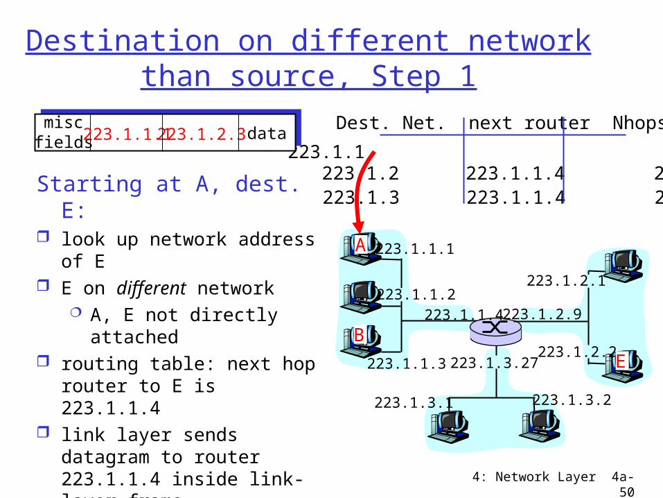
Destination on different network than source, Step 1
223.1.1.1
223.1.1.2
223.1.1.3
223.1.1.4 223.1.2.9
223.1.2.2
223.1.2.1
223.1.3.2223.1.3.1
223.1.3.27
A
BE
Dest. Net. next router Nhops
223.1.1 1223.1.2 223.1.1.4 2223.1.3 223.1.1.4 2
Starting at A, dest. E: look up network address of
E E on different network
A, E not directly attached
routing table: next hop router to E is 223.1.1.4
link layer sends datagram to router 223.1.1.4 inside link-layer frame
datagram arrives at 223.1.1.4
continued…..
miscfields223.1.1.1223.1.2.3 data

4: Network Layer 4a-51
Destination on different network than source, Step 2
223.1.1.1
223.1.1.2
223.1.1.3
223.1.1.4 223.1.2.9
223.1.2.2
223.1.2.1
223.1.3.2223.1.3.1
223.1.3.27
A
BE
Arriving at 223.1.4, destined for 223.1.2.2
look up network address of E
E on same network as router’s interface 223.1.2.9 router, E directly
attached link layer sends datagram
to 223.1.2.2 inside link-layer frame via interface 223.1.2.9
datagram arrives at 223.1.2.2!!! (hooray!)
miscfields223.1.1.1223.1.2.3 data network router Nhops interface
223.1.1 - 1 223.1.1.4 223.1.2 - 1 223.1.2.9
223.1.3 - 1 223.1.3.27
Dest. next

4: Network Layer 4a-52
Router Architecture Overview
Two key router functions:
run routing algorithms/protocol (RIP, OSPF, BGP) switching datagrams from incoming to outgoing link

4: Network Layer 4a-53
Input Port Functions
Decentralized switching: given datagram dest., lookup output
port using routing table in input port memory
goal: complete input port processing at ‘line speed’
queuing: if datagrams arrive faster than forwarding rate into switch fabric
Physical layer:bit-level reception
Data link layer:e.g., Ethernet

Network Layer 4-54
Switching fabrics transfer packet from input buffer to
appropriate output buffer switching rate: rate at which packets can be
transfer from inputs to outputs often measured as multiple of input/output line rate N inputs: switching rate N times line rate desirable
three types of switching fabrics
memory
memory
bus crossbar

4: Network Layer 4a-55
Switching Via MemoryFirst generation routers: packet copied by system’s (single) CPU speed limited by memory bandwidth (2 bus crossings per datagram)
InputPort
OutputPort
Memory
System Bus

4: Network Layer 4a-56
Switching Via Bus
datagram from input port memory
to output port memory via a shared bus – not through system memory
bus contention: switching speed limited by bus bandwidth
Sufficient speed for access and enterprise routers (not regional or backbone)

Network Layer 4-57
Switching Via An Interconnection Network
Overcome simple bus bandwidth limitations
Banyan networks, crossbar, other interconnection nets initially developed to connect processors in multiprocessor
advanced design: fragmenting datagram into fixed length cells, switch cells through the fabric. Ie through the interconnection network
crossbar

4: Network Layer 4a-58
Multistage Fabrics
Hardware arranged in sets and a transfer from input to output involves transfers through multiple sets
Ex. First number says which first stage, second number says which second stage
Switch 1
Switch 2
Switch 3
Switch 4
00
01
10
11
Banyan switch
4: Network Layer 4a-59
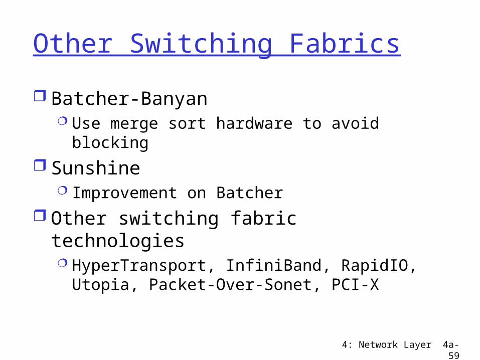
Other Switching Fabrics
Batcher-Banyan Use merge sort hardware to avoid blocking
Sunshine Improvement on Batcher
Other switching fabric technologies HyperTransport, InfiniBand, RapidIO, Utopia,
Packet-Over-Sonet, PCI-X

4: Network Layer 4a-60
Input Port Queuing
Fabric slower that input ports combined -> queueing may occur at input queues
Head-of-the-Line (HOL) blocking: queued datagram at front of queue prevents others in queue from moving forward
queueing delay and loss due to input buffer overflow!

4: Network Layer 4a-61
Output Ports
Buffering required when datagrams arrive from fabric faster than the transmission rate
Scheduling discipline chooses among queued datagrams for transmission

4: Network Layer 4a-62
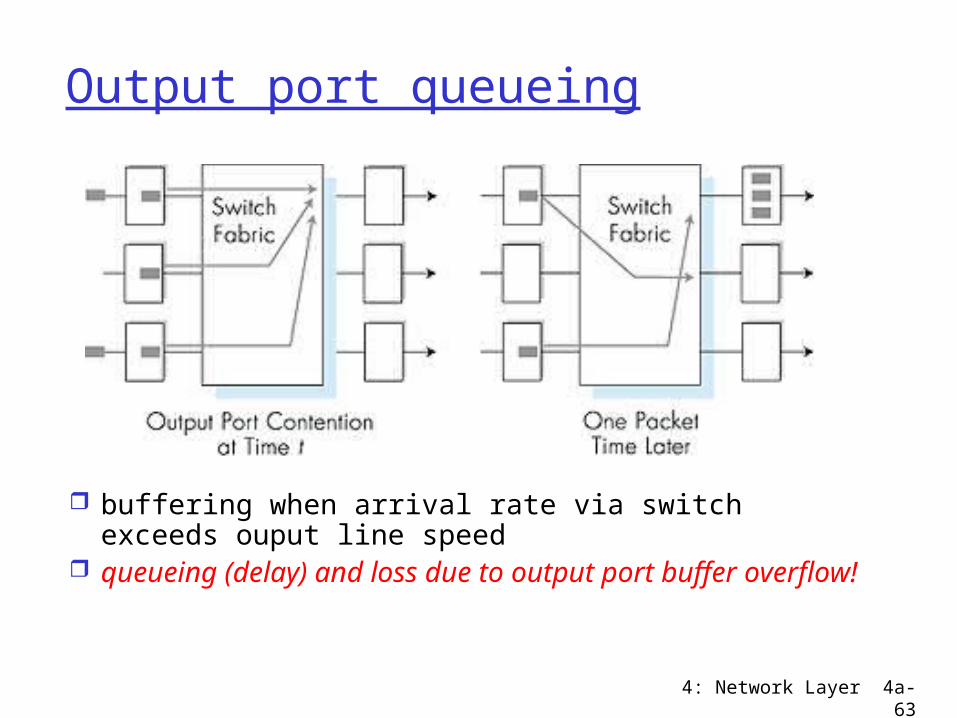
Output port queueing
buffering when arrival rate via switch exceeds ouput line speed
queueing (delay) and loss due to output port buffer overflow!
4: Network Layer 4a-63
Output port queueing
buffering when arrival rate via switch exceeds ouput line speed
queueing (delay) and loss due to output port buffer overflow!

4: Network Layer 4a-64
Router Hardware

4: Network Layer 4a-65
Router Configuration
Router Software: operating system with built in applications (command line interpreters, web servers)
Configure Each Interface Configure Routing Protocol

4: Network Layer 4a-66
Outtakes
4: Network Layer 4a-67
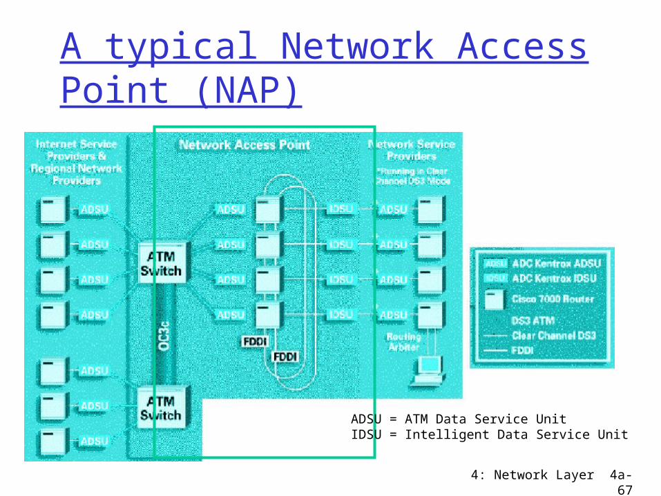
A typical Network Access Point (NAP)
ADSU = ATM Data Service UnitIDSU = Intelligent Data Service Unit

4: Network Layer 4a-68
A small Internet
ethernet
link
host
router
FDDIDivision A
Division B
Pac.Bell
MCI
aol.com

4: Network Layer 4a-69
Why different Intra- and Inter-AS routing ?
Policy: Inter-AS: admin wants control over how its traffic
routed, who routes through its net. Intra-AS: single admin, so no policy decisions
needed
Scale: hierarchical routing saves table size, reduced
update trafficPerformance: Intra-AS: can focus on performance Inter-AS: policy may dominate over performance

4: Network Layer 4a-70
CAIDA: Layout showing Major ISPs

4: Network Layer 4a-71
Routing = giving directions Switching = moving packets from
incoming to outgoing interface
4: Network Layer 4a-72
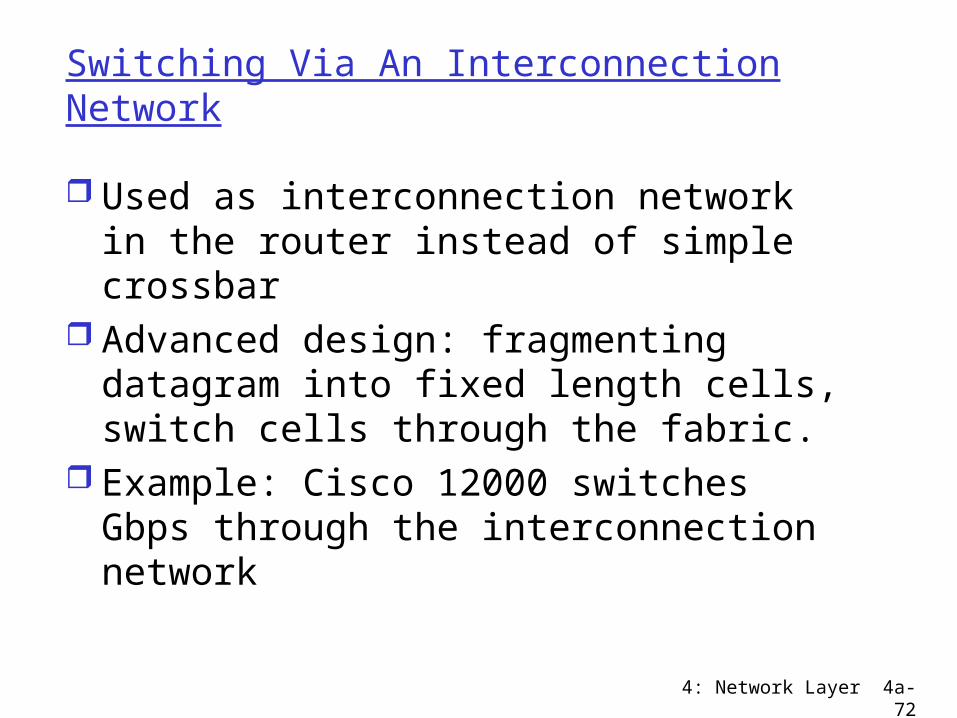
Switching Via An Interconnection Network
Used as interconnection network in the router instead of simple crossbar
Advanced design: fragmenting datagram into fixed length cells, switch cells through the fabric.
Example: Cisco 12000 switches Gbps through the interconnection network
4: Network Layer 4a-73
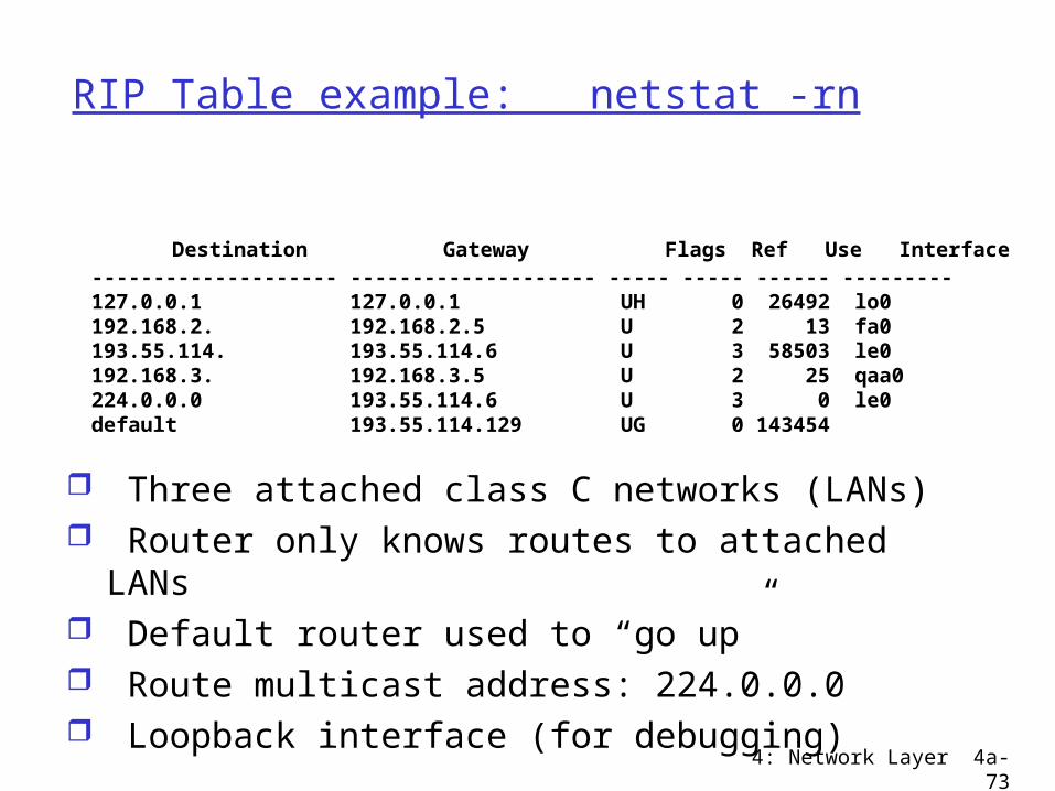
RIP Table example: netstat -rn
Three attached class C networks (LANs) Router only knows routes to attached LANs Default router used to “go up” Route multicast address: 224.0.0.0 Loopback interface (for debugging)
Destination Gateway Flags Ref Use Interface -------------------- -------------------- ----- ----- ------ --------- 127.0.0.1 127.0.0.1 UH 0 26492 lo0 192.168.2. 192.168.2.5 U 2 13 fa0 193.55.114. 193.55.114.6 U 3 58503 le0 192.168.3. 192.168.3.5 U 2 25 qaa0 224.0.0.0 193.55.114.6 U 3 0 le0 default 193.55.114.129 UG 0 143454


