Progress In Electromagnetics Research C, Vol. 46, 163–170, 2014 Planar Ultrawideband Monopole Antenna with Tri-Notch Band Characteristics Sai K. Venkata, Muktikanta Rana, Pritam S. Bakariya * , Santanu Dwari, and Manas Sarkar Abstract—In this article, a compact ultra-wideband (UWB) planar monopole antenna with the triple notched band is pro pose d. The ante nna consi sts of a semicircu lar radia ting patch and a modi fied groun d plane with two bevels at upper edge. By etching two round shape slots in radiating patch the notc h characte ristic s are achieved at WiMax band (3.3–3.7 GHz) and WLAN band (5.15–5.875GHz). In order to realize notch band at X-band downlink satell ite communic ation band (7.1–7.76 GHz) a pair of rotated V-shape slot are etched on the groun d plane. The measured operating impedance bandwidth of proposed ante nna ranges from 2.9 to 10.9 GHz having return loss less than 10dB with triple notched bands. The proposed antenna exhibits a nearl y omnidi rectio nal radiation pattern in the H-plane, and a dipole-like radiation pattern in the E-plane for the ultra-wi deband. The effects of each individu al slot on band-notc h cha racter istics are also inv estigated. The measured gain of the proposed triple band notched antenna is relatively stable across the operating frequency band except notched bands and there by making the proposed ante nna suitable for practical UWB applications. Propose d antenna has a compact size of 27 × 25mm 2 . 1. INTRODUCTION Planar monopole ultrawide band (UWB) antenna has dra wn wide in ter est from the res earchers for incre asing the data rate in wirele ss communicat ion, since the F ederal Communicat ions Commission (FCC) released 3.1 to 10.6 GHz as an unlic ensed band for radio communicat ion. Due to many attractiv e features, such as simple structure, small size, light weight, and low cost, printed monopole antennas are the most freq uen tly used ante nnas for UWB applicatio ns [1–4]. How eve r, the planar monopole ante nna design for UWB communication system is still facing many challenges. The UWB communication system has allowed very low power emission level, thus it could be easily interfered by nearby communication systems suc h as WiMax communicatio n sys tem oper ating at 3.5 GHz (3.4 –3.7 GHz ), WLA N sys tem suc h as IEEE 802.11/a operating at 5.2 GHz (5.15–5. 35 GHz, 5.725–5.875 GHz) and X-ba nd downli nk communica tion freque ncy operating at 7.5 (7.1–7.7 6 GHz). So the interfer ences of these narro wband communic atio n systems with UWB sys tems sho uld be av oided for better perfor mance. T o av oid interfer ence, band-s top filer can be used. How eve r, the use of band-stop filter requires more space to integrate, and it also increases the cost and complexity of the system. A better way to avoid interference is using UWB ante nna with band-notch char acteri stic. In the last few years, various UWB antennas with band-notch characteristics have been reported. The most general method is to etch slots of different shapes either on radiating patch or in the ground or in micros trip, adding circuit stub, using metamateria l reson ator [5–8]. Using these techniques, many antennas have been reported to achieve single notch band [9–14], dual band notch [15–20] and triple notch band [21–24] in UWB region. Received 23 December 2013, Accepted 16 January 2014, Scheduled 22 January 2014 * Corres ponding author: Pritam Singh Bak ariya (pritam.gs @gmail. com). The authors are with the Departmen t of Electr onics Engineer ing, Indian School of Mines , Dhan bad, Jharkhand 826004, India.
Transcript
7/24/2019 4 Pier Paper
http://slidepdf.com/reader/full/4-pier-paper 1/8
Progress In Electromagnetics Research C, Vol. 46, 163–170, 2014
Planar Ultrawideband Monopole Antenna with
Tri-Notch Band Characteristics
Sai K. Venkata, Muktikanta Rana, Pritam S. Bakariya*,Santanu Dwari, and Manas Sarkar
Abstract—In this article, a compact ultra-wideband (UWB) planar monopole antenna with the triplenotched band is proposed. The antenna consists of a semicircular radiating patch and a modifiedground plane with two bevels at upper edge. By etching two round shape slots in radiating patch thenotch characteristics are achieved at WiMax band (3.3–3.7 GHz) and WLAN band (5.15–5.875 GHz).In order to realize notch band at X-band downlink satellite communication band (7.1–7.76 GHz) a pairof rotated V-shape slot are etched on the ground plane. The measured operating impedance bandwidthof proposed antenna ranges from 2.9 to 10.9 GHz having return loss less than 10 dB with triple notchedbands. The proposed antenna exhibits a nearly omnidirectional radiation pattern in the H -plane, anda dipole-like radiation pattern in the E -plane for the ultra-wideband. The effects of each individualslot on band-notch characteristics are also investigated. The measured gain of the proposed triple bandnotched antenna is relatively stable across the operating frequency band except notched bands andthereby making the proposed antenna suitable for practical UWB applications. Proposed antenna hasa compact size of 27× 25mm2.
1. INTRODUCTION
Planar monopole ultrawideband (UWB) antenna has drawn wide interest from the researchers forincreasing the data rate in wireless communication, since the Federal Communications Commission(FCC) released 3.1 to 10.6 GHz as an unlicensed band for radio communication. Due to many attractivefeatures, such as simple structure, small size, light weight, and low cost, printed monopole antennas arethe most frequently used antennas for UWB applications [1–4]. However, the planar monopole antennadesign for UWB communication system is still facing many challenges. The UWB communication systemhas allowed very low power emission level, thus it could be easily interfered by nearby communicationsystems such as WiMax communication system operating at 3.5 GHz (3.4–3.7GHz), WLAN systemsuch as IEEE 802.11/a operating at 5.2 GHz (5.15–5.35 GHz, 5.725–5.875 GHz) and X-band downlinkcommunication frequency operating at 7.5 (7.1–7.76 GHz). So the interferences of these narrowbandcommunication systems with UWB systems should be avoided for better performance. To avoid
interference, band-stop filer can be used. However, the use of band-stop filter requires more space tointegrate, and it also increases the cost and complexity of the system. A better way to avoid interferenceis using UWB antenna with band-notch characteristic.
In the last few years, various UWB antennas with band-notch characteristics have been reported.The most general method is to etch slots of different shapes either on radiating patch or in the groundor in microstrip, adding circuit stub, using metamaterial resonator [5–8]. Using these techniques, manyantennas have been reported to achieve single notch band [9–14], dual band notch [15–20] and triplenotch band [21–24] in UWB region.
Received 23 December 2013, Accepted 16 January 2014, Scheduled 22 January 2014
* Corresponding author: Pritam Singh Bakariya ([email protected]).The authors are with the Department of Electronics Engineering, Indian School of Mines, Dhanbad, Jharkhand 826004, India.
7/24/2019 4 Pier Paper
http://slidepdf.com/reader/full/4-pier-paper 2/8
164 Venkata et al.
In this article, a novel UWB printed monopole antenna with triple bands notched characteristicsis proposed. The band-notch characteristics are obtained by two round shape slots etched on radiatingpatch and a pair of rotated V-shape slot [25] in the ground plane. The length of each slot has been takenabout half of the guided wavelength at their respective notched band frequency. The position of eachnotched band can be controlled individually according to requirements of the system by changing the
dimension or position of their respective slot. The effect of each slot has been optimized and discussedin detail. The proposed antenna exhibits a nearly omnidirectional radiation pattern in the H -planeand a dipole-like radiation pattern in the E -plane for the entire UWB. In comparison to the antennasin [21–23], this antenna is compact in size, and in comparison to [24], the radiation pattern is morestable at passband of the ultrawideband renge. Moreover, the cross polarization level of the proposedantenna is better than that of [24].
2. ANTENNA DESIGN AND ANALYSIS
Figure 1 shows the geometry and configuration of the proposed monopole antenna. The antenna hasa compact size of 27 × 25mm2. This antenna is printed on FR4 substrate of 0.8 mm thickness witha dielectric constant of 4.4 and loss tangent of 0.02. It is composed of a 50-Ω microstrip feed line, aplanar radiating patch with two round shape slots and rectangular ground plane with a pair of rotated
V-shape slots. Several aspects were considered to optimize the final design like the overall impedancebandwidth of the antenna, the bandwidth of the notched bands, and the level of band rejection atnotched frequency. The optimal antenna parameters are obtained as follows: L = 27mm, W = 25mm,d = 5.5mm, R1 = 6mm, R2 = 4.5mm, R3 = 12mm, W 1 = 0.2mm, W 2 = 0.4mm, L1 = 2mm,L2 = 2.5mm, L3 = 5.1mm.
(a) (b) (c)
Figure 1. (a) Schematic of proposed antenna. (b) Front view of fabricated antenna. (c) Bottom viewof fabricated antenna.
Commercial simulation software Ansoft HFSS 14 was used to perform the parametric study of proposed antenna. The individual effect of different parameters of each slot like slot length, width andtheir position have been investigated. To create a band-notch characteristics within the UWB there aretwo round shape slots S 1 and S 2 etched on the radiating patch and a pair of rotated V-shape slots S 3aand S 3b etched in the ground plane as shown in Figure 1. The length of each slot has been taken abouthalf of the guided wavelength.
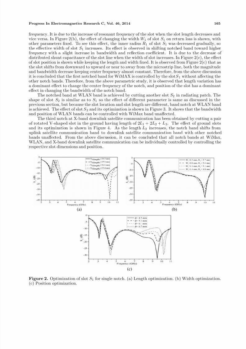
Figure 2 shows the effect of different parameters of slot S 1 etched in radiating patch. The length of slot S 1 is taken about half of the guided wavelength at a center frequency of WiMax band 3.5 GHz (3.3–3.7 GHz). The slot length optimization is shown in Figure 2(a), and it is observed that as it decreases,the center frequency shifts toward higher frequency, while it increases the response shifts toward lower
7/24/2019 4 Pier Paper
http://slidepdf.com/reader/full/4-pier-paper 3/8
Progress In Electromagnetics Research C, Vol. 46, 2014 165
frequency. It is due to the increase of resonant frequency of the slot when the slot length decreases andvice versa. In Figure 2(b), the effect of changing the width W 1 of slot S 1 on return loss is shown, withother parameters fixed. To see this effect, the inner radius R1 of slot S 1 was decreased gradually, sothe effective width of slot S 1 increases. Its effect is observed in shifting notched band toward higherfrequency with a slight increase in bandwidth and reflection coefficient. It is due to the decrease of
distributed shunt capacitance of the slot line when the width of slot increases. In Figure 2(c), the effectof slot position is shown while keeping the length and width fixed. It is observed from Figure 2(c) that asthe slot shifts from downward to upward or near to away from the microstrip line, both the magnitudeand bandwidth decrease keeping center frequency almost constant. Therefore, from the above discussionit is concluded that the first notched band for WiMAX is controlled by the slot S 1 without affecting theother notch bands. Therefore, from the above parametric study, it is observed that length variation hasa dominant effect to change the center frequency of the notch, and position of the slot has a dominanteffect in changing the bandwidth of the notch band.
The notched band at WLAN band is achieved by cutting another slot S 2 in radiating patch. Theshape of slot S 2 is similar as to S 1 so the effect of different parameter is same as discussed in theprevious section, but because the slot location and slot length are different, band notch at WLAN bandis achieved. The effect of slot S 2 and its optimization is shown in Figure 3. It shows that the bandwidthand position of WLAN bands can be controlled with WiMax band unaffected.
The third notch at X-band downlink satellite communication has been obtained by cutting a pairof rotated V-shaped slot in the ground having length of 2L1 + 2L2 + L3. The effect of ground slotsand its optimization is shown in Figure 4. As the length L2 increases, the notch band shifts fromuplink satellite communication band to downlink satellite communication band with other notchedbands unaffected. From the above discussion, it can be concluded that all notch bands at WiMax,WLAN, and X-band downlink satellite communication can be individually controlled by controlling therespective slot dimensions and position.
(a) (b)
(c)
Figure 2. Optimization of slot S 1 for single notch. (a) Length optimization. (b) Width optimization.(c) Position optimization.
7/24/2019 4 Pier Paper
http://slidepdf.com/reader/full/4-pier-paper 4/8
166 Venkata et al.
(a) (b)
Figure 3. Optimization of slot S 2 for dual notch. (a) Length optimization. (b) Width optimization.
Figure 4. Optimization of slot S 3 position bychanging L2.
Figure 5. Simulated and measured reflectioncoefficient of the printed UWB antenna.
(a) (b)
(c) (d)
Figure 6. Surface current distributions on the radiating patch at (a) 4.5 GHz, and at the notchfrequencies of (b) 3.5 GHz, (c) 5.5 GHz, (e) 7.5 GHz.
7/24/2019 4 Pier Paper
http://slidepdf.com/reader/full/4-pier-paper 5/8
Progress In Electromagnetics Research C, Vol. 46, 2014 167
(a)
(c)
(e)
(g)
(b)
(d)
(f)
(h)
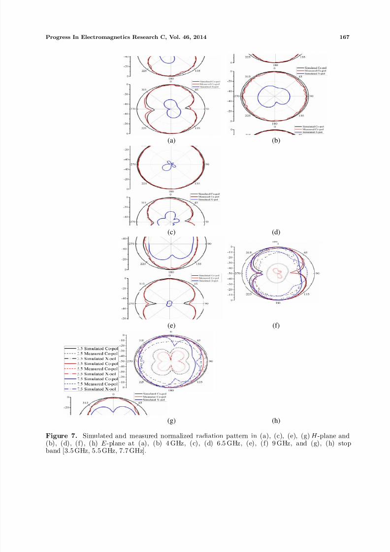
Figure 7. Simulated and measured normalized radiation pattern in (a), (c), (e), (g) H -plane and(b), (d), (f), (h) E -plane at (a), (b) 4 GHz, (c), (d) 6.5 GHz, (e), (f) 9 GHz, and (g), (h) stopband [3.5 GHz, 5.5 GHz, 7.7 GHz].
7/24/2019 4 Pier Paper
http://slidepdf.com/reader/full/4-pier-paper 6/8
168 Venkata et al.
3. RESULTS AND DISCUSSION
The return loss of the proposed antenna was measured using an Agilent N5242A vector network analyzer.The measured and simulated results for return loss are shown in Figure 5. The measured and simulatedresults show good agreement at lower frequencies, but with increases in frequency, the measured resultshows slight variations. It may be due to some measurement or fabrication errors, or it may also beexpected due to some parametric differences between the practical and simulated models.
The effect of different slots S 1, S 2 and S 3 in getting the notch band can also be clearly examinedby surface current distribution. The simulated surface current distribution of proposed antenna onradiating patch at different frequency is analyzed as shown in Figure 6. In Figure 6(a), it is observedthat at pass band frequency of 4.5 GHz the surface current is distributed uniformly over antenna.The current distribution at notch frequencies are shown in Figures 6(b)–(d) and these show very strongcurrent distribution concentrated around slot S 1, S 2 and S 3 at a center frequency of notch band 3.5 GHz,5.5 GHz and 7.5 GHz, respectively. The strong current distributions around slots at the notch frequencyleads to near field radiation counteracted, due to which high energy is reflected back to the input portand the band-notched characteristics achieved [18]. It also can be noticed that in Figures 6(b)–(d) thereare very low mutual coupling at the notch frequencies, which indicate that each rejected band can becontrolled independently.
The measured and simulated far-field radiation patterns of the proposed antenna in H
-plane (XZ
-plane) and E -plane (Y Z -plane) at pass-band frequency of 4 GHz, 6.5 GHz, 9 GHz and at the stopband of 3.5 GHz, 5.5 GHz, 7.5 GHz are shown in Figure 7. The antenna has a nice omnidirectionalradiation pattern in H -plane and bidirectional pattern in E -plane. The cross polarization levels atnotch band frequency are observed, which shows that at stop band frequencies, the cross polarizationlevels are increased in comparison to passband frequencies. The antenna exhibits stable radiationpatterns throughout the UWB.
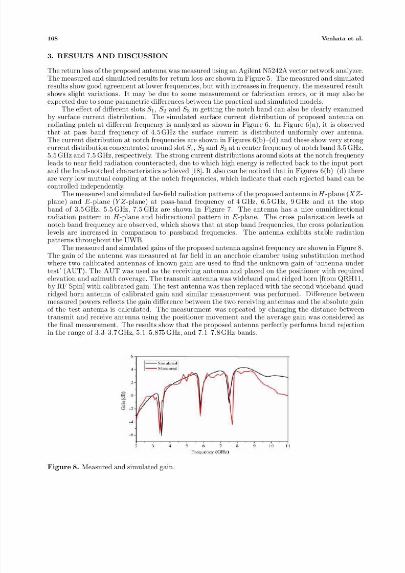
The measured and simulated gains of the proposed antenna against frequency are shown in Figure 8.The gain of the antenna was measured at far field in an anechoic chamber using substitution methodwhere two calibrated antennas of known gain are used to find the unknown gain of ‘antenna undertest’ (AUT). The AUT was used as the receiving antenna and placed on the positioner with requiredelevation and azimuth coverage. The transmit antenna was wideband quad ridged horn [from QRH11,by RF Spin] with calibrated gain. The test antenna was then replaced with the second wideband quad
ridged horn antenna of calibrated gain and similar measurement was performed. Difference betweenmeasured powers reflects the gain difference between the two receiving antennas and the absolute gainof the test antenna is calculated. The measurement was repeated by changing the distance betweentransmit and receive antenna using the positioner movement and the average gain was considered asthe final measurement. The results show that the proposed antenna perfectly performs band rejectionin the range of 3.3–3.7 GHz, 5.1–5.875 GHz, and 7.1–7.8 GHz bands.
Figure 8. Measured and simulated gain.
7/24/2019 4 Pier Paper
http://slidepdf.com/reader/full/4-pier-paper 7/8
Progress In Electromagnetics Research C, Vol. 46, 2014 169
4. CONCLUSION
A printed monopole antenna with three band notched characteristics is proposed for UWB applications.The band-notch characteristics are achieved by etching two round shape slots in radiating patch anda pair of rotated V-shapes at ground. The length of each slot has been taken about half of guidedwavelength. It has been observed that by changing the dimension and location of different slots, eachnotched band can be controlled independently, without affecting the UWB performance, which offersa great freedom to select the notch frequency band for the band-notch antenna. The measured andsimulated results reveal that the antenna has a stable far-field radiation pattern in H - and E -planesthroughout the UWB. Stable gain has been observed, except at the notched frequency. The presentedantenna is suitable for practical UWB applications.
REFERENCES
1. Rambabu, K., H. A. Thiart, and J. Bornemann, “Ultrawideband printed circuit antenna,” IEEE Trans. Antennas and Propagation , Vol. 54, No. 12, 3908–3911, 2006.
2. Azenui, N. C. and H. Y. D. Yang, “A printed crescent patch antenna for ultrawidebandapplications,” IEEE Antenna. Wireless Propag. Lett., Vol. 6, 113–116, 2007.
3. Li, L., Z. I. Zhou, J. S. Hong, and B. Z. Wang, “Compact ultra-wideband printed monopoleantenna,” Electronics Letters , Vol. 47, No. 16, 894–896, 2011.
4. Huang, C.-Y. and G. H. Chen, “Compact self complementary antenna for ultrawidebandapplications,” Microwave and Optical Technology Letters , Vol. 54, No. 9, 2144–2146, Sep. 2012.
5. Lin, Y. C. and K. J. Hung, “Compact ultrawideband rectangular aperture antenna and band-notched designs,” IEEE Trans. Antennas and Propagation , Vol. 54, No. 11, 3075–3081, 2006.
6. Kim, J., C. S. Chou, and J. W. Lee, “5.2GHz notched ultra-wideband antenna using slot-typeSRR,” Electronics Letters , Vol. 42, No. 6, 315–316, 2006.
7. Li, W., X. Shi, T. Zhang, and Y. Song, “Novel UWB planar monopole antenna with dual band-notched characteristics,” Microwave and Optical Technology Letters , Vol. 52, No. 1, 48–51, 2010.
8. Kim, K. H., Y. J. Cho, S. H. Hwang, and S. O. Park, “Band-notched UWB planar monopoleantenna with two parasitic patches,” Electronics Letters , Vol. 41, No. 14, 783–785, 2005.
9. Gao, G. P., M. Li, S. F. Niu, X. J. Li, B. N. Li, and J. S. Zhang, “Study of a novel wideband circularslot antenna having frequency band-notched function,” Progress In Electromagnetics Research ,Vol. 96, 141–154, 2009.
10. Hu, Y. S., M. Li, G. P. Gao, J. S. Zhang, and M. K. Yang, “A double-printed trapezoidalpatch dipole antenna for UWB applications with band-notched characteristic,” Progress In Electromagnetics Research , Vol. 103, 259–269, 2010.
11. Zhang, K., Y. Li, and Y. Long, “Band notched UWB printed monopole antenna with a novelsegmented circular patch,” IEEE Antenna. Wireless Propag. Lett., Vol. 9, 1209–1212, 2010.
12. Lee, W.-S., D. Z. Kim, K.-J. Kim, and J.-W. Yu, “Wideband planar monopole antennas with dualband notched characteristics,” IEEE Transactions on Microwave Theory and Techniques , Vol. 54,No. 6, 2800–2806, 2006.
13. Azim, R., A. T. Mobashsher, and M. T. Islam, “UWB antenna with notched band at 5.5 GHz,”Electronics Letters , Vol. 49 No. 15, 922–924, 2013.
14. Azim, R. and M. T. Islam, “Compact planar UWB antenna with band notch characteristics forWLAN and DSRC,” Progress In Electromagnetics Research , Vol. 133, 391–406, 2013.
15. Zhu, F., S. Gao, A. T. S. Ho, C. H. See, R. A. Abd-Alhameed, J. Li, and J. Xu, “Design and analysisof planar ultra-wideband antenna with dual band-notched function,” Progress In Electromagnetics Research , Vol. 127, 523–536, 2012.
16. Sarkar, M., S. Dwari, and A. Daniel, “Compact printed monopole antenna for ultra-widebandapplication with dual band notched characteristic,” Microwave and Optical Technology Letters ,Vol. 55, No. 11, 2595–2600, 2013.
7/24/2019 4 Pier Paper
http://slidepdf.com/reader/full/4-pier-paper 8/8
170 Venkata et al.
17. Tang, M. C., S. Xiao, T. Deng, D. Wang, J. Guan, B. Wang, and G. D. Ge, “Compact UWB antennawith multiple band-notches for WiMAX and WLAN,” IEEE Trans. Antennas and Propagation ,Vol. 59, No. 4, 1372–1376, 2011.
18. Fan, S.-T., Y.-Z. Yin, H. Li, and L. Kahn, “A novel self-similar antenna for UWB applications withband-notched characteristics,” Progress In Electromagnetics Research Letters , Vol. 22, 1–8, 2011.
19. Azim, R., M. T. Islam, and A. T. Mobashsher, “Design of a dual band-notch UWB slot antenna bymeans of simple parasitic slits,” IEEE Antenna. Wireless Propag. Lett., Vol. 12, 1412–1415, 2013.
20. Yazdi, M. and N. Komjani, “A compact band-notched UWB planar monopole antenna withparasitic elements,” Progress In Electromagnetics Research Letters , Vol. 24, 129–138, 2011.
21. Kim, D. O. and C. Y. Kim, “CPW fed ultrawideband antenna with triple band notch function,”Electronics Letters , Vol. 46, No. 18, 1246–1248, Sep. 2010.
22. Nguyen, T. D., D. H. Lee, and H. C. Park, “Design and analysis of compact printed triple bandnotched UWB antenna,” IEEE Antenna. Wireless Propag. Lett., Vol. 10, 403–406, 2011.
23. Liu, J., K. P. Esselle, S. G. Hay, and S. S. Zhong, “Study of an extremely wideband monopoleantenna with triple band-notched characteristics,” Progress In Electromagnetics Research , Vol. 123,143–158, 2012.
24. Islam, M. T., R. Azim, and A. T. Mobashsher, “Triple band-notched planar UWB antenna using
parasitic strips,” Progress In Electromagnetics Research , Vol. 129, 161–179, 2012.25. Rostamzadeh, M., S. Mohamadi, J. Nourinia, C. Ghobadi, and M. Ojaroudi, “Square monopole
antenna for UWB applications with novel rod-shaped parasitic structures and novel V-shaped slotsin the ground plane,” IEEE Antenna. Wireless Propag. Lett., Vol. 11, 446–449, 2012.