DI-22 DIFFERENTIALS REAR DIFFERENTIAL 4. Rear Differential A: REMOVAL 1) Set the vehicle on a lift. 2) Disconnect the ground cable from battery. 3) Move the select lever or gear shift lever to “N”. 4) Release the parking brake. 5) Loosen the wheel nuts. 6) Jack-up the vehicle and support it with sturdy racks. 7) Remove the wheels. 8) Disconnect the connector from oil temperature switch. (STi model) 9) Remove the rear exhaust pipe and muffler. SOHC model <Ref. to EX(H4SO)-8, REMOVAL, Rear Exhaust Pipe.> and <Ref. to EX(H4SO)-9, REMOVAL, Muf- fler.> DOHC Turbo model <Ref. to EX(H4DOTC)-13, REMOVAL, Rear Ex- haust Pipe.> and <Ref. to EX(H4DOTC)-14, RE- MOVAL, Muffler.> 10) Remove the heat shield cover. (If equipped) 11) Remove the front cover of rear differential mount. 12) Remove the propeller shaft. <Ref. to DS-14, REMOVAL, Propeller Shaft.> 13) Remove the rear differential protector. (If equipped) 14) Remove the clamps and bracket of parking brake cable. 15) Remove the DOJ of rear drive shaft from rear differential using ST. <Ref. to DI-50, REPLACE- MENT, Rear Differential Side Oil Seal.> ST 28099PA100 DRIVE SHAFT REMOVER 16) Secure the rear drive shaft to rear crossmem- ber using wire. (A) Connector DI-00348 (A) DI-00050 (A) Bolt DI-00051 DI-00052 (A) ST DI-00053
Transcript
DI-22
DIFFERENTIALSREAR DIFFERENTIAL
4. Rear DifferentialA: REMOVAL1) Set the vehicle on a lift.2) Disconnect the ground cable from battery.3) Move the select lever or gear shift lever to “N”.4) Release the parking brake.5) Loosen the wheel nuts.6) Jack-up the vehicle and support it with sturdyracks.7) Remove the wheels.8) Disconnect the connector from oil temperatureswitch. (STi model)
9) Remove the rear exhaust pipe and muffler.SOHC model<Ref. to EX(H4SO)-8, REMOVAL, Rear ExhaustPipe.> and <Ref. to EX(H4SO)-9, REMOVAL, Muf-fler.>DOHC Turbo model<Ref. to EX(H4DOTC)-13, REMOVAL, Rear Ex-haust Pipe.> and <Ref. to EX(H4DOTC)-14, RE-MOVAL, Muffler.>10) Remove the heat shield cover. (If equipped)11) Remove the front cover of rear differentialmount.
12) Remove the propeller shaft. <Ref. to DS-14,REMOVAL, Propeller Shaft.>13) Remove the rear differential protector. (Ifequipped)
14) Remove the clamps and bracket of parkingbrake cable.
15) Remove the DOJ of rear drive shaft from reardifferential using ST. <Ref. to DI-50, REPLACE-MENT, Rear Differential Side Oil Seal.>ST 28099PA100 DRIVE SHAFT REMOVER
16) Secure the rear drive shaft to rear crossmem-ber using wire.
(A) Connector
DI-00348
(A)
DI-00050
(A) Bolt
DI-00051
DI-00052(A)
ST
DI-00053
DI-23
DIFFERENTIALSREAR DIFFERENTIAL
17) Remove the lower bracket.
18) Support the rear differential with transmissionjack.
19) Remove the self-locking nuts and bolts.
20) Remove the bolts which secure the rear differ-ential front member to body.Loosen the bolt A first, then remove the bolts B.
NOTE:Support the front member with use of a helper toprevent it from dropping.
21) Remove the bolt A.22) While slowly lowering the transmission jack,move the rear differential forward and remove frontmember and rear differential from vehicle.
23) Remove the rear differential from vehicle.
(A) Lower bracket
(A)
DI-00122
DI-00055
DI-00314
(A) Bolt A
(B) Bolt B
DI-00057
(B)
(B)(A)
DI-00058
DI-00059
DI-24
DIFFERENTIALSREAR DIFFERENTIAL
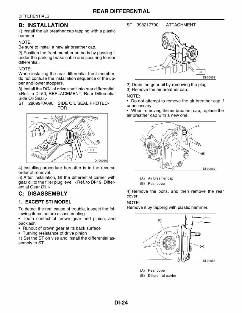
B: INSTALLATION1) Install the air breather cap tapping with a plastichammer.
NOTE:Be sure to install a new air breather cap.2) Position the front member on body by passing itunder the parking brake cable and securing to reardifferential.
NOTE:When installing the rear differential front member,do not confuse the installation sequence of the up-per and lower stoppers.3) Install the DOJ of drive shaft into rear differential.<Ref. to DI-50, REPLACEMENT, Rear DifferentialSide Oil Seal.>ST 28099PA090 SIDE OIL SEAL PROTEC-
TOR
4) Installing procedure hereafter is in the reverseorder of removal.5) After installation, fill the differential carrier withgear oil to the filler plug level. <Ref. to DI-19, Differ-ential Gear Oil.>
C: DISASSEMBLY1. EXCEPT STi MODELTo detect the real cause of trouble, inspect the fol-lowing items before disassembling.• Tooth contact of crown gear and pinion, andbacklash• Runout of crown gear at its back surface• Turning resistance of drive pinion1) Set the ST on vise and install the differential as-sembly to ST.
ST 398217700 ATTACHMENT
2) Drain the gear oil by removing the plug.3) Remove the air breather cap.
NOTE:• Do not attempt to remove the air breather cap ifunnecessary.• When removing the air breather cap, replace theair breather cap with a new one.
4) Remove the bolts, and then remove the rearcover.
NOTE:Remove it by tapping with plastic hammer.
ST
DI-00060
(A) Air breather cap
(B) Rear cover
(A) Rear cover
(B) Differential carrier
ST
DI-00061
(A)
(B)
DI-00062
(A)
(B)
DI-00063
DI-25
DIFFERENTIALSREAR DIFFERENTIAL
5) Make right and left side bearing retainers in or-der to identify them at reassembly. Remove theside bearing retainer attaching bolts, set the ST todifferential case, and extract right and left sidebearing retainers with a puller.
NOTE:Each shim, which is installed to adjust the sidebearing preload, should be kept together with itsmating retainer.ST 398457700 ATTACHMENT
6) Pull out the differential case assembly from dif-ferential carrier.
NOTE:Be careful not to hit the teeth against the case.
7) When replacing the side bearing, pull the bear-ing cup from side bearing retainer using ST.ST 398527700 PULLER ASSY
8) Extract the bearing cone with ST.
NOTE:• Do not attempt to disassemble the parts unlessnecessary.• Set the puller so that its claws catch the edge ofbearing cone.• Never mix up the right and left hand bearing rac-es and cones.ST 18759AA000 PULLER ASSY
9) Remove the crown gear by loosening the crowngear bolts.
10) Drive out the pinion shaft lock pin from crowngear side. (Model without LSD)
NOTE:The lock pin is staked at the pin hole end on the dif-ferential carrier; do not drive it out forcibly beforeunstaking it.ST 899904100 STRAIGHT PIN REMOVER
ST
DI-00064
DI-00065
ST
DI-00066
DI-00316
ST
DI-00068
DI-00237
DI-26
DIFFERENTIALSREAR DIFFERENTIAL
11) Draw out the pinion mate shaft and remove thepinion mate gears, side gears and thrust washers.(Model without LSD)
NOTE:The gears as well as thrust washers should bemarked or kept separated right and left, front andrear.
12) Hold the companion flange with ST and removethe drive pinion nut.ST 498427200 FLANGE WRENCH
13) Extract the companion flange with a puller.
14) Press the end of drive pinion shaft and extract ittogether with the rear bearing cone, preload adjust-ing spacer and washer.
NOTE:Hold the drive pinion so as not to drop it.ST 398467700 DRIFT
15) Remove the rear bearing cone from drive pin-ion by supporting the cone with ST.
NOTE:Place the replacer so that its center-recessed sidefaces the pinion gear.ST 398517700 REPLACER
16) Remove the front oil seal from differential carri-er using ST.ST 398527700 PULLER ASSY
(A) Side gear
(B) Pinion mate gear
(C) Thrust washer
(D) Differential case
(E) Pinion mate shaft
DI-00238
ST
DI-00071
DI-00072
ST
DI-00073
ST
DI-00074
DI-00075
DI-27
DIFFERENTIALSREAR DIFFERENTIAL
17) Remove the pilot bearing together with frontbearing cone using ST.ST 398467700 DRIFT
18) When replacing the bearings, hit out the frontbearing cup and rear bearing cup in this order out ofcase by using a brass bar.
2. STi MODELTo detect the real cause of trouble, inspect the fol-lowing items before disassembling.• Tooth contact of crown gear and pinion, andbacklash• Runout of crown gear at its back surface• Turning resistance of drive pinion1) Set the ST on vise and install the differential as-sembly to ST.
ST 398217700 ATTACHMENT
2) Drain the gear oil by removing the plug.3) Remove the air breather cap.
NOTE:• Do not attempt to remove the air breather cap ifunnecessary.• When removing the air breather cap, replace theair breather cap with a new one.
4) Remove the bolts, and then remove the rearcover.
NOTE:Remove it by tapping with plastic hammer.
(A) Pilot bearing
(B) Spacer
(C) Front bearing
(D) Rear bearing cup
(A) 2 cutouts along diagonal lines
(B) Hit out alternately with brass bar.
ST
(B)(A)(C)
(D)
DI-00076
(B)
(A)
DI-00077(A) Air breather cap
(B) Rear cover
(A) Rear cover
(B) Differential carrier
ST
DI-00061
DI-00346
(A)
(B)
(A)
(B)
DI-00063
DI-28
DIFFERENTIALSREAR DIFFERENTIAL
5) Make right and left side bearing retainers in or-der to identify them at reassembly. Remove theside bearing retainer attaching bolts, set the ST todifferential case, and extract right and left sidebearing retainers with a puller.
NOTE:Each shim, which is installed to adjust the sidebearing preload, should be kept together with itsmating retainer.ST 398457700 ATTACHMENT
6) Pull out the differential case assembly from dif-ferential carrier.
NOTE:Be careful not to hit the teeth against the case.
7) When replacing the side bearing, pull the bear-ing cup from side bearing retainer using ST.ST 398527700 PULLER ASSY
8) Extract the bearing cone with ST.
NOTE:• Do not attempt to disassemble the parts if unnec-essary.• Set the puller so that its claws catch the edge ofbearing cone.• Never mix up the right and left hand bearing rac-es and cones.ST 18759AA000 PULLER ASSY
9) Remove the crown gear by loosening the crowngear bolts.
NOTE:Disassembling the differential case is not allowed.
10) Hold the companion flange with ST and removethe drive pinion nut.ST 18633AA000 WRENCH COMPL
ST
DI-00064
DI-00065
ST
DI-00066
DI-00316
ST
DI-00068
ST
DI-00071
DI-29
DIFFERENTIALSREAR DIFFERENTIAL
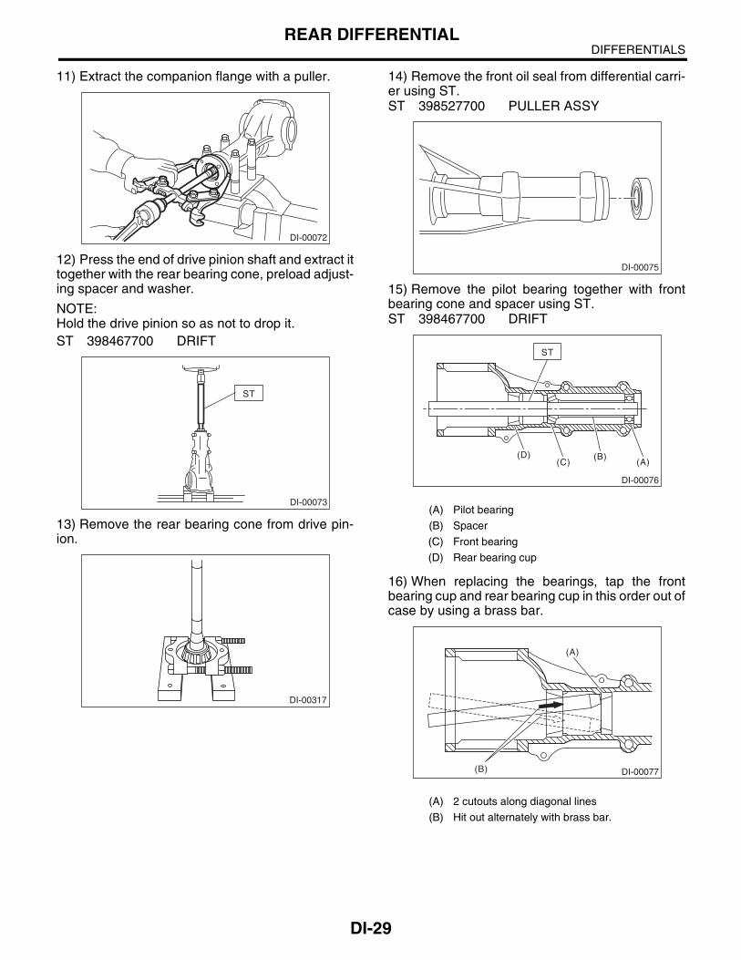
11) Extract the companion flange with a puller.
12) Press the end of drive pinion shaft and extract ittogether with the rear bearing cone, preload adjust-ing spacer and washer.
NOTE:Hold the drive pinion so as not to drop it.ST 398467700 DRIFT
13) Remove the rear bearing cone from drive pin-ion.
14) Remove the front oil seal from differential carri-er using ST.ST 398527700 PULLER ASSY
15) Remove the pilot bearing together with frontbearing cone and spacer using ST.ST 398467700 DRIFT
16) When replacing the bearings, tap the frontbearing cup and rear bearing cup in this order out ofcase by using a brass bar.
DI-00072
ST
DI-00073
DI-00317
(A) Pilot bearing
(B) Spacer
(C) Front bearing
(D) Rear bearing cup
(A) 2 cutouts along diagonal lines
(B) Hit out alternately with brass bar.
DI-00075
ST
(B)(A)(C)
(D)
DI-00076
(B)
(A)
DI-00077
DI-30
DIFFERENTIALSREAR DIFFERENTIAL
D: ASSEMBLY1. EXCEPT STi MODEL
NOTE:• Assemble in the reverse order of disassembling.• Check and adjust each part during assembly.• Keep the shims and washers in order, so thatthey are not improperly installed.• Thoroughly clean the surfaces on which theshims, washers and bearings are to be installed.• Apply gear oil when installing the bearings andthrust washers.• Be careful not to mix up the right and left handraces of the bearings.• Use a new O-ring and gasket.• Replace the oil seal with a new one at every dis-assembly. Apply chassis grease between the lipswhen installing the oil seal.• Be careful not to confuse the installing directionof oil seal.
1) Adjusting preload for front and rear bearingsAdjust the bearing preload with spacer and washerbetween front and rear bearings. Pinion height ad-justing washer are not affected by this adjustment.The adjustment must be carried out without oil sealinserted.
(1) Press the rear bearing race into differentialcarrier using ST1 and ST2.
ST1 398477701 HANDLEST2 398477703 DRIFT 2
(2) Install the front bearing race to differentialcarrier using ST1 and ST2.
ST1 398477701 HANDLEST2 398477703 DRIFT 2
(3) Insert the ST1 into carrier with pinion heightadjusting washer and rear bearing cone fittedonto it.
NOTE:• If tooth contact (Drive pinion, Crown gear) is nor-mal in the inspection before disassembling, verifythat the washer is not deformed, and then re-usethe used washer.• Use a new rear bearing cone.
(4) Then install the preload adjusting spacerand washer, front bearing cone, ST2, compan-ion flange, and washer and drive pinion nut.
(5) Turn the ST1 with hand to make it seated,and tighten the drive pinion nut while measuringthe preload with spring balance. Select the pre-load adjusting washer and spacer so that thespecified preload is obtained when nut is tight-ened to the specified torque.
DI-00078
ST2ST1
DI-00079
(A) Pinion height adjusting shim
(B) Preload adjusting spacer
(C) Preload adjusting washer
(B)(A)(C)
ST2 ST1 DI-00080
DI-00117
DI-31
DIFFERENTIALSREAR DIFFERENTIAL
NOTE:• Use a new lock nut.• Be careful not to give excessive preload.• When tightening the drive pinion nut, lock ST1with ST2 as shown in the figure.• Measure the preload in direction of tangent toflange.ST1 398507702 DUMMY SHAFTST2 398507704 BLOCK
Tightening torque:181 N·m (18.5 kgf-m, 134 ft-lb)
2) Adjusting drive pinion heightAdjust the drive pinion height with shim installedbetween the rear bearing cone and back of piniongear.
(1) Install the ST2.
NOTE:At this time, install a pinion height adjusting shimwhich is temporarily selected or the same as thatused before. Measure and record the thickness.ST1 398507702 DUMMY SHAFTST2 398507701 DIFFERENTIAL CARRIER
GAUGEST3 398507703 DUMMY COLLAR
Front and rear bearing preload
For new bearing:18.1 — 38.8 N (1.8 — 4.0 kgf, 4.1 — 8.7 lb)at companion flange bolt hole
ST1
ST2
DI-00081
DI-00117
Preload adjusting washer
Part No.Thicknessmm (in)
383705200 2.59 (0.1020)
383715200 2.57 (0.1012)
383725200 2.55 (0.1004)
383735200 2.53 (0.0996)
383745200 2.51 (0.0988)
383755200 2.49 (0.0980)
383765200 2.47 (0.0972)
383775200 2.45 (0.0965)
383785200 2.43 (0.0957)
383795200 2.41 (0.0949)
383805200 2.39 (0.0941)
383815200 2.37 (0.0933)
383825200 2.35 (0.0925)
383835200 2.33 (0.0917)
383845200 2.31 (0.0909)
Preload adjusting spacer
Part No. Length mm (in)
383695201 56.2 (2.213)
383695202 56.4 (2.220)
383695203 56.6 (2.228)
383695204 56.8 (2.236)
383695205 57.0 (2.244)
383695206 57.2 (2.252)
(A) Pinion height adjusting shim
RH
LH
N
(A)
ST2ST3 ST1
DI-00083
DI-32
DIFFERENTIALSREAR DIFFERENTIAL
(2) Measure the clearance N between the endof ST2 and end surface of ST1 by using a thick-ness gauge.
NOTE:Make sure there is no clearance between the caseand ST2.ST1 398507702 DUMMY SHAFTST2 398507701 DIFFERENTIAL CARRIER
GAUGE
(3) Obtain the thickness of pinion height adjust-ing shim to be inserted from the following formu-la, and replace the temporarily installed shimwith this one.
T = To + N − (H × 0.01) − 0.20 mm (0.0079 in)
NOTE:Use copies of this page.
(Example of calculation)To = 2.20 + 1.20 = 3.40 mmN = 0.23 mm H = + 1T = 3.40 + 0.23 − 0.01 − 0.20 = 3.42Result: Thickness = 3.42 mm
Therefore use the shim 383605200.
3) Install the selected pinion height adjusting shimon drive pinion, and press the rear bearing coneinto position with ST.ST 398177700 INSTALLER
4) Insert the drive pinion into differential carrier, in-stall the previously selected bearing preload adjust-ing spacer and washer.
T Thickness of pinion height adjusting shim mm (in)
To Thickness of shim temporarily inserted mm (in)
N Reading of thickness gauge mm (in)
H Figure marked on drive pinion head
Memo:
Pinion height adjusting shim
Part No. Thickness mm (in)
383495200 3.09 (0.1217)
383505200 3.12 (0.1228)
383515200 3.15 (0.1240)
383525200 3.18 (0.1252)
383535200 3.21 (0.1264)
383545200 3.24 (0.1276)
383555200 3.27 (0.1287)
383565200 3.30 (0.1299)
ST2
ST1
DI-00084
383575200 3.33 (0.1311)
383585200 3.36 (0.1323)
383595200 3.39 (0.1335)
383605200 3.42 (0.1346)
383615200 3.45 (0.1358)
383625200 3.48 (0.1370)
383635200 3.51 (0.1382)
383645200 3.54 (0.1394)
383655200 3.57 (0.1406)
383665200 3.60 (0.1417)
383675200 3.63 (0.1429)
383685200 3.66 (0.1441)
(A) Drive pinion
(B) Bearing adjusting spacer
(C) Washer
(D) Differential carrier
Pinion height adjusting shim
Part No. Thickness mm (in)
ST
DI-00085
(A)
(B)
(C)
(D)DI-00086
DI-33
DIFFERENTIALSREAR DIFFERENTIAL
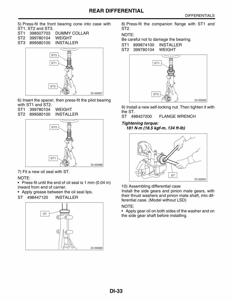
5) Press-fit the front bearing cone into case withST1, ST2 and ST3.ST1 398507703 DUMMY COLLARST2 399780104 WEIGHTST3 899580100 INSTALLER
6) Insert the spacer, then press-fit the pilot bearingwith ST1 and ST2.ST1 399780104 WEIGHTST2 899580100 INSTALLER
7) Fit a new oil seal with ST.
NOTE:• Press-fit until the end of oil seal is 1 mm (0.04 in)inward from end of carrier.• Apply grease between the oil seal lips.ST 498447120 INSTALLER
8) Press-fit the companion flange with ST1 andST2.
NOTE:Be careful not to damage the bearing.ST1 899874100 INSTALLERST2 399780104 WEIGHT
9) Install a new self-locking nut. Then tighten it withthe ST.ST 498427200 FLANGE WRENCH
Tightening torque:181 N·m (18.5 kgf-m, 134 ft-lb)
10) Assembling differential caseInstall the side gears and pinion mate gears, withtheir thrust washers and pinion mate shaft, into dif-ferential case. (Model without LSD)
NOTE:• Apply gear oil on both sides of the washer and onthe side gear shaft before installing.
ST3
ST1
ST2
DI-00087
ST2
ST1
DI-00088
ST
DI-00089
ST1
ST2
DI-00090
STDI-00091
DI-34
DIFFERENTIALSREAR DIFFERENTIAL
• Insert the pinion mate shaft into the differentialcase by aligning the lock pin holes.
(1) Measure the side gear backlash.
Side gear backlash:0.10 — 0.20 mm (0.0039 — 0.0079 in)
(2) Adjust the backlash as specified by select-ing the side gear thrust washer.
(3) Check the condition of rotation after apply-ing oil to the gear tooth surfaces and thrust sur-faces.(4) After inserting the pinion shaft lock pin intodifferential case, stake both sides of the hole toprevent pin from falling off.
11) Install the crown gear on differential case.
NOTE:Before installing the bolts, apply Lock Tite to boltthreads.
Lock Tite:THREE BOND 1324 (Part No. 004403042) or equivalent
NOTE:Tighten diagonally while tapping the bolt heads.
(6) Measure the crown gear-to-drive pinionbacklash. Set the magnet base on differentialcarrier. Align the contact point of dial gauge withtooth face of crown gear, and move the crowngear while holding drive pinion still. Read thevalue indicated on dial gauge.
Backlash:0.10 — 0.20 mm (0.0039 — 0.0079 in)
(7) At the same time, measure the total preloadof drive pinion. Compared with the resistancewhen differential case is not installed, if the totalpreload is not within specification, adjust thethickness of side bearing retainer shims, in-creasing/reducing by an even amount at a time.
Total preload:20.7 — 54.4 N (2.1 — 5.5 kgf, 4.7 — 12.2 lb)
15) Re-check the crown gear-to-pinion backlash.
Backlash:0.10 — 0.20 mm (0.0039 — 0.0079 in)
Side bearing retainer shim
Part No. Thickness mm (in)
383475201 0.20 (0.0079)
383475202 0.25 (0.0098)
383475203 0.30 (0.0118)
383475204 0.40 (0.0157)
383475205 0.50 (0.0197)
(A) Arrow mark
DI-00065
(A)
DI-00097
DI-00098
DI-00099
DI-00099
DI-36
DIFFERENTIALSREAR DIFFERENTIAL
16) Check the crown gear runout on its back sur-face, and make sure that pinion and crown gear ro-tate smoothly.
Limit of runout:Less than 0.05 mm (0.0020 in)
17) Checking and adjusting tooth contact of crowngear
(1) Apply an even coat of red lead on both sidesof three or four teeth on the crown gear. Checkthe contact pattern after rotating the crown gearseveral revolutions back and forth until a definitecontact pattern appears on the crown gear.(2) When the contact pattern is incorrect, read-just according to the instructions given in“TOOTH CONTACT PATTERN”.
NOTE:Be sure to wipe off red lead completely after adjust-ment is completed.• Correct tooth contactChecking item: Tooth contact pattern is slightlyshifted toward to toe side under no-loadrotation. (When loaded, contact pattern movestoward heel)
• Face contactChecking item: Backlash is too large.Contact pattern
Corrective action: Increase thickness of drive pin-ion height adjusting shim in order to bring drive pin-ion close to crown gear.
• Flank contactChecking item: Backlash is too small.Contact pattern
(A) Toe side
(B) Heel side
DI-00101
AT-00207
(A)
(B)
AT-00208
AT-00212
AT-00209
DI-37
DIFFERENTIALSREAR DIFFERENTIAL
Corrective action: Reduce thickness of drive pinionheight adjusting shim in order to move drive pinionaway from crown gear.
• Toe contact (Inside end contact)Checking item: Contact area is small.Contact pattern
Corrective action: Reduce thickness of drive pinionheight adjusting shim in order to move drive pinionaway from crown gear.
• Heel contact (Outside end contact)Checking item: Contact area is small.
Contact pattern
Corrective action: Increase thickness of drive pin-ion height adjusting shim in order to bring drive pin-ion close to crown gear.
18) If proper tooth contact is not obtained, onceagain adjust the drive pinion height by changing RHand LH side bearing retainer shims and the hypoidgear backlash.19) Remove the side bearing retainers on right andleft side. 20) Install new O-rings to side bearing retainers onright and left side.21) Install the oil seals to side bearing retainers onright and left side.22) Align the arrow mark on differential carrier withthe mark on side retainer during installation.
AT-00213
AT-00210
AT-00213
(A) Arrow mark
AT-00211
AT-00212
(A)
DI-00097
DI-38
DIFFERENTIALSREAR DIFFERENTIAL
23) Tighten the side bearing retainer bolts.
Lock Tite:THREE BOND 1105 (Part No. 004403010) or equivalent
24) Install the new gasket and rear cover and tight-en the bolts to specified torque.
Tightening torque:29 N·m (3.0 kgf-m, 21.7 ft-lb)
25) Install the breather cap.26) Install the drain plug and filler plug.
Tightening torque:49 N·m (5.0 kgf-m, 36.2 ft-lb)
2. STi MODEL1) Precautions for assembling• Assemble in the reverse order of disassembling.• Check and adjust each part during assembly.• Keep the shims and washers in order, so thatthey are not improperly installed.• Thoroughly clean the surfaces on which theshims, washers and bearings are to be installed.• Apply gear oil when installing the bearings andthrust washers.• Be careful not to mix up the right and left handraces of the bearings.
• Replace the oil seal with a new one at every dis-assembly. Apply chassis grease between the lipswhen installing the oil seal.
• Adjust the bearing preload with spacer andwasher between front and rear bearings. Pinionheight adjusting shim are not affected by this ad-justment. The adjustment must be carried out with-out oil seal inserted.2) Press-fit the rear bearing race into differentialcarrier using ST.ST 398417700 DRIFT
3) Press-fit the front bearing race into differentialcarrier using ST.ST 398477702 DRIFT
DI-00098
DI-00113
DI-00078
DI-00318
ST
DI-00319
DI-39
DIFFERENTIALSREAR DIFFERENTIAL
4) Pinion height adjusting shim selection.(1) Measure the thickness of inserted pinionheight adjusting shim.
(2) Read the punch mark of installed drive pin-ion gear and new one.
NOTE:If there is no punch mark, it means 0 (zero).
(3) Obtain the thickness of pinion height adjustshim to be inserted from the following formula,and replace the inserted shim with this one.
T = T1 + (T2 × 0.01 − T3 × 0.01)
(Example of calculation)T1 = 3.30, T2 = +2, T3 = −1T = 3.30 + {(2 × 0.01) − (−1 × 0.01)} = 3.33Result: Thickness = 3.33 mm
Therefore use the shim 38336AA310.
5) Install the selected pinion height adjusting shimon drive pinion, and press-fit the rear bearing coneinto position with ST.ST 18674AA000 INSTALLER
6) Insert the drive pinion into differential carrier, in-stall the previously selected bearing preload adjust-ing spacer and washer.
T mm
Thickness of selected pinion height adjusting shim.
T1 mm
Thickness of inserted pinion height adjusting shim.
T2 mm
Punch mark number on installed drive pinion gear.
T3 mm
Punch mark number on new drive pinion gear.
Pinion height adjusting shim
Part No. Thickness T mm (in)
38336AA230 3.09 (0.1217)
38336AA240 3.12 (0.1228)
38336AA250 3.15 (0.1240)
38336AA260 3.18 (0.1252)
38336AA270 3.21 (0.1264)
DI-00320
0
0
55
10
10
15
DI-00321
+2
38336AA280 3.24 (0.1276)
38336AA290 3.27 (0.1287)
38336AA300 3.30 (0.1299)
38336AA310 3.33 (0.1311)
38336AA320 3.36 (0.1323)
38336AA330 3.39 (0.1335)
38336AA340 3.42 (0.1346)
38336AA350 3.45 (0.1358)
38336AA360 3.48 (0.1370)
38336AA370 3.51 (0.1382)
38336AA380 3.54 (0.1394)
38336AA390 3.57 (0.1406)
38336AA400 3.60 (0.1417)
38336AA410 3.63 (0.1429)
38336AA420 3.66 (0.1441)
(A) Drive pinion
(B) Bearing preload adjusting spacer
(C) Bearing preload adjusting washer
(D) Differential carrier
Pinion height adjusting shim
Part No. Thickness T mm (in)
ST
DI-00085
(A)
(B)
(C)
(D)DI-00086
DI-40
DIFFERENTIALSREAR DIFFERENTIAL
7) Insert the spacer, then press-fit the pilot bearingwith STs.ST1 399780104 WEIGHTST2 899580100 INSTALLERST3 398507703 DUMMY COLLERST4 498937110 HOLDER DRIVE PINION
8) Press-fit the companion flange with ST1, ST2and ST3.
NOTE:Be careful not to damage the bearing.ST1 899874100 INSTALLERST2 399780104 WEIGHTST3 498937110 HOLDER DRIVE PINION
9) Install the self-locking nut. Then tighten it withthe ST.ST 18633AA000 WRENCH COMPL
Tightening torque:181 N·m (18.5 kgf-m, 134 ft-lb)
10) Rotate the drive pinion shaft more than tentimes to accustom each taper roller bearing, andthen measure the preload.
18) Press-fit the side bearing onto differential casewith ST.ST 398487700 DRIFT
19) Assembling side retainer.(1) Press-fit the side bearing outer race withpress and ST.
DI-00072
ST
DI-00089
DI-00323
ST3
ST1
ST2ST2
ST
DI-00071
DI-00068
ST
DI-00095
DI-42
DIFFERENTIALSREAR DIFFERENTIAL
ST 398417700 DRIFT
(2) Install the oil seal. <Ref. to DI-50, RE-PLACEMENT, Rear Differential Side Oil Seal.>
20) Adjusting side bearing retainer shims(1) The driven gear backlash and side bearingpreload can be determined by the side bearingretainer shim thickness.(2) Install the differential case assembly into dif-ferential carrier in the reverse order of disas-sembly.
(3) Install the side retainer shims to the rightand left retainers from which they were re-moved.
NOTE:Replace the broken or corroded side retainer shimwith a new one of same thickness.
(4) Align the arrow mark on differential carrierwith the mark on side retainer during installation.
NOTE:Be careful that side bearing outer race is not dam-aged by bearing roller.
(6) Measure the crown gear-to-drive pinionbacklash. Set the magnet base on differentialcarrier. Align the contact point of dial gauge withtooth face of crown gear, and move the crowngear while holding drive pinion still. Read thevalue indicated on dial gauge.
Backlash:0.10 — 0.20 mm (0.0039 — 0.0079 in)
Side bearing retainer shim
Part No. Thickness mm (in)
383475201 0.20 (0.0079)
383475202 0.25 (0.0098)
383475203 0.30 (0.0118)
383475204 0.40 (0.0157)
383475205 0.50 (0.0197)
DI-00324
ST
DI-00065
(A) Arrow mark
(A)
DI-00097
DI-00098
DI-00099
DI-43
DIFFERENTIALSREAR DIFFERENTIAL
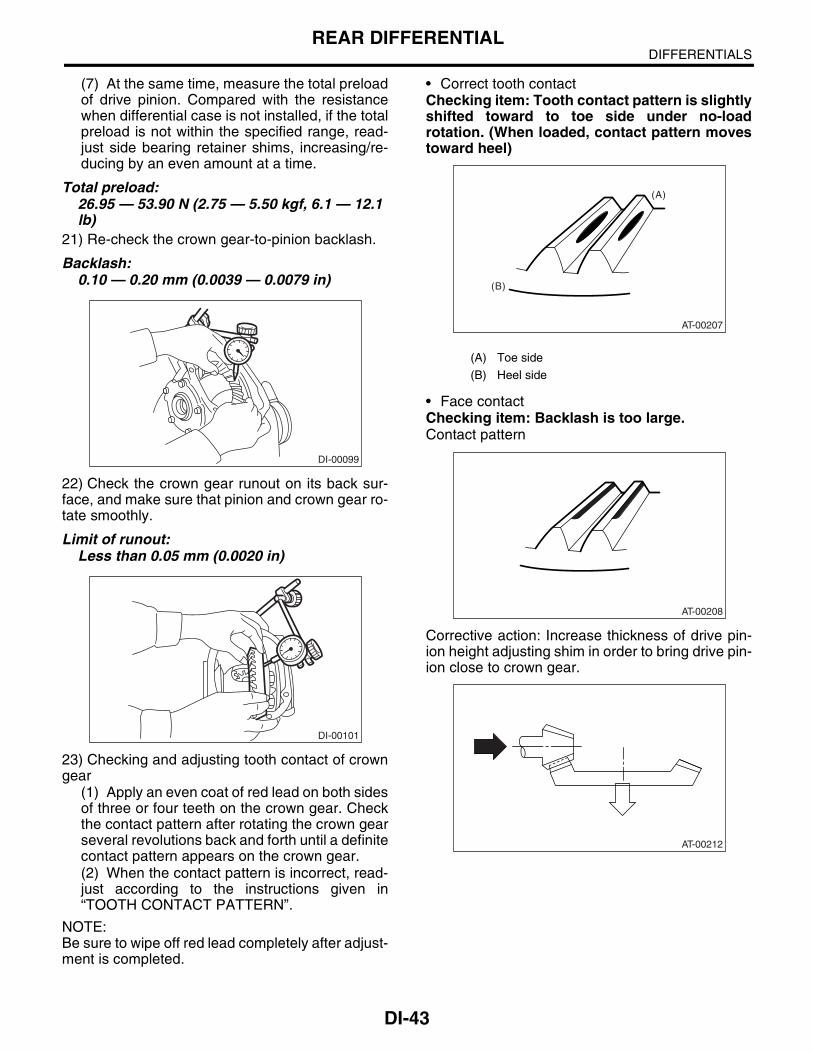
(7) At the same time, measure the total preloadof drive pinion. Compared with the resistancewhen differential case is not installed, if the totalpreload is not within the specified range, read-just side bearing retainer shims, increasing/re-ducing by an even amount at a time.
Total preload:26.95 — 53.90 N (2.75 — 5.50 kgf, 6.1 — 12.1 lb)
21) Re-check the crown gear-to-pinion backlash.
Backlash:0.10 — 0.20 mm (0.0039 — 0.0079 in)
22) Check the crown gear runout on its back sur-face, and make sure that pinion and crown gear ro-tate smoothly.
Limit of runout:Less than 0.05 mm (0.0020 in)
23) Checking and adjusting tooth contact of crowngear
(1) Apply an even coat of red lead on both sidesof three or four teeth on the crown gear. Checkthe contact pattern after rotating the crown gearseveral revolutions back and forth until a definitecontact pattern appears on the crown gear.(2) When the contact pattern is incorrect, read-just according to the instructions given in“TOOTH CONTACT PATTERN”.
NOTE:Be sure to wipe off red lead completely after adjust-ment is completed.
• Correct tooth contactChecking item: Tooth contact pattern is slightlyshifted toward to toe side under no-loadrotation. (When loaded, contact pattern movestoward heel)
• Face contactChecking item: Backlash is too large.Contact pattern
Corrective action: Increase thickness of drive pin-ion height adjusting shim in order to bring drive pin-ion close to crown gear.
DI-00099
DI-00101
(A) Toe side
(B) Heel side
AT-00207
(A)
(B)
AT-00208
AT-00212
DI-44
DIFFERENTIALSREAR DIFFERENTIAL
• Flank contactChecking item: Backlash is too small.Contact pattern
Corrective action: Reduce thickness of drive pinionheight adjusting shim in order to move drive pinionaway from crown gear.
• Toe contact (Inside end contact)Checking item: Contact area is small.Contact pattern
Corrective action: Reduce thickness of drive pinionheight adjusting shim in order to move drive pinionaway from crown gear.
• Heel contact (Outside end contact)Checking item: Contact area is small.Contact pattern
Corrective action: Increase thickness of drive pin-ion height adjusting shim in order to bring drive pin-ion close to crown gear.
24) If proper tooth contact is not obtained, onceagain adjust the drive pinion height by changing RHand LH side bearing retainer shims and the hypoidgear backlash.25) Remove the side bearing retainers on right andleft side. 26) Install new O-rings to side bearing retainers onright and left side.
AT-00209
AT-00213
AT-00210
AT-00213
AT-00211
AT-00212
DI-45
DIFFERENTIALSREAR DIFFERENTIAL
27) Align the arrow mark on differential carrier withthe mark on side retainer during installation.
28) Tighten the side bearing retainer bolts.
Lock Tite:THREE BOND 1105 (Part No. 004403010) or equivalent
29) Install the new gasket, rear cover and stayground and tighten the bolts to specified torque.
Tightening torque:44 N·m (4.5 kgf-m, 32.5 ft-lb)
30) Install the breather cap.31) Install the drain plug and rear differential oiltemperature switch or oil temperature sensor.
Tightening torque:49 N·m (5.0 kgf-m, 36.2 ft-lb)
E: INSPECTIONWash all the disassembled parts clean, and exam-ine them for wear, damage, or other defects. Re-pair or replace defective parts as necessary.1) Crown gear and drive pinion• If abnormal tooth contact is evident, find out thecause and adjust to give correct tooth contact at as-sembly. Replace the gear if excessively worn or in-capable of adjustment.• If crack, score, or seizure is evident, replace as aset. Slight damage of tooth can be corrected by oilstone or the like.2) Side gear and pinion mate gear• Replace if crack, score, or other defects are evi-dent on tooth surface.• Replace if thrust washer contacting surface isworn or seized. Slight damage of the surface canbe corrected by oil stone or the like.3) BearingReplace if seizure, peeling, wear, rust, draggingduring rotation, abnormal noise or other defect isevident.4) Thrust washers of side gear and pinion mategearReplace if seizure, flaw, abnormal wear or otherdefect is evident.5) Oil sealReplace if deformed or damaged, and at every dis-assembling.6) Differential carrierReplace if the bearing bores are worn or damaged.7) Differential caseReplace if its sliding surfaces are worn or cracked.8) Companion flangeReplace if the oil seal lip contacting surfaces haveflaws.9) Rear differential oil temperature switchIf the results of the following inspections are notsatisfactory, replace rear differential temperatureswitch.(1) At room temperature, check for continuity be-tween the sensor terminal and body.(2) Soak the sensor in oil, then raise the oil temper-ature. Check that the continuity is cut off when theoil temperature is between 144°C (291°F) and156°C (313°F). Then, check that the continuity re-sumes by the time the oil temperature drops to135°C (275°F).
(A) Arrow mark
(A) Stay ground
(A)
DI-00097
DI-00098
DI-00345
(A)
DI-46
DIFFERENTIALSREAR DIFFERENTIAL
1. SIDE GEAR BACKLASHUsing a dial gauge, check the backlash of the sidegear.
Side gear backlash:0.1 — 0.2 mm (0.004 — 0.008 in)
If the side gear backlash is not within the specifica-tion, adjust clearance as specified by selecting theside gear thrust washer.
2. CROWN GEAR BACKLASHUsing a dial gauge, check the backlash of thecrown gear.
Crown gear backlash:0.1 — 0.2 mm (0.004 — 0.008 in)
If the crown gear backlash is not within the specifi-cation, adjust the side bearing preload or repair ifnecessary.
3. CROWN GEAR RUNOUTUsing a dial gauge, check the crown gear runout.
Crown gear runout:Less than 0.05 mm (0.0020 in)
If the crown gear runout exceeds 0.05 mm (0.0020in), replace the crown gear.
4. TOOTH CONTACT BETWEEN CROWN GEAR AND DRIVE PINIONInspect the tooth contact between crown gear anddriven pinion. <Ref. to DI-30, ASSEMBLY, RearDifferential.>
5. TOTAL PRELOADUsing a gauge, check the turning resistance in-crease.
If the total preload is not within the specification,adjust the side bearing retainer shims.
DI-00315
DI-00099
DI-00101
DI-00117
DI-47
DIFFERENTIALSREAR DIFFERENTIAL
F: ADJUSTMENT1. SIDE GEAR BACKLASHAdjust the side gear backlash. <Ref. to DI-30, AS-SEMBLY, Rear Differential.>
2. CROWN GEAR BACKLASHAdjust the crown gear backlash. <Ref. to DI-30,ASSEMBLY, Rear Differential.>
3. TOOTH CONTACT BETWEEN CROWN GEAR AND DRIVE PINIONAdjust the tooth contact between crown gear anddrive pinion gear. <Ref. to DI-30, ASSEMBLY,Rear Differential.>
4. TOTAL PRELOADAdjust the side bearing shim. <Ref. to DI-30, AS-SEMBLY, Rear Differential.>