Page 1
4-1
4. SOIL MINERALOGY
4.1 INTRODUCTION
Any definition of the term soil will take into account aspects of behaviour in which
the user has a predominant interest. Four ways in which soil could be defined are:
1. The material on natural surfaces in which vegetation takes root.
2. A limited section (beneath natural surface) extending from decomposed rock
to the surface.
3. Any loose fragmental material which can be readily broken into grains or
masses of coherent clays.
4. The loose fragmental materials of the earth’s crust.
Soil Mechanics could be loosely defined as the application of the principles of
mechanics and hydraulics to the study of soil. In this context “study” would include
examination of behavioural changes that occur when soil is subjected to changes of stress,
deformation, or environmental conditions.
The examination of soil behaviour can be performed at two levels: a consideration
that response can be explained by considering soil to be an assemblage of solid soil particles,
air and water; or a study at the atomic level where surface forces are considered.
It could be thought that a study at the atomic level would provide a more
fundamental understanding of soil behaviour than that conducted at the “assemblage” level.
Whilst this is true for some limited aspects of soil behaviour, in particular the response of
“fine grained” soils to changes in moisture, the major thrust in research has been the
explanation of soil behaviour on the engineering (or assemblage) level.
This course will concentrate on studies of soil behaviour at the engineering level. To
explain adequately an observed response to some change in condition reference will be made
to atomic structure.
A first course in soil mechanics can be confusing. Problems posed in elementary
statics and fluid mechanics are usually quite clear-cut and well defined, each question having
Page 2
4-2
its own unambiguous answer. The solution to problems involving soil response is not so
straightforward, because:
(a) boundary conditions may be ill-defined, and
(b) material properties are variable, and in some cases unknown.
Problem solving in soil mechanics usually entails;
(a) a recognition of the physical problem.
(b) an idealisation of this real situation into a model of behaviour.
(c) the solution of the idealised model using relationships of solid mechanics or
fluid mechanics.
(d) a consideration of the applicability of the answers to this simplified problem
with respect to the physical situation.
(A solution process common to all engineering problems).
4.2 SOIL FORMATION
4.2.1 Weathering
Implicit within the definition of soil is the notion that soil is the product of
decomposition from rock sources. (An exception are the organic soil materials). A detailed
study of soil formation will not be attempted in this introductory presentation.
Four stages can be identified in the formation of soil.
1. Weathering and Transportation.
2. Deposition.
3. Sediment alteration.
4. Movements of the earth’s crust.
Page 3
4-3
Not all are essential. Weathering may occur without transportation and subsequent
deposition, in which case a “residual soil” is formed.
Weathering can be classified, simply, as physical or chemical. The more common
agents associated with physical weathering are water, temperature and stress relief (uplift).
Chemical weathering can occur at normal (surface) temperatures or can be associated with
temperatures in excess of 100˚C and pressures greater than one atmosphere. (For a discussion
on transformation that occurs at elevated temperatures and pressures see, for example, Grim
(1968), Ch. 13).
The products of weathering can be transported via wind, water, ice or mass
movements (landslides). In all cases further degradation of the parent material or alteration of
the sediment can occur.
When the transportation velocity is slow enough, particles in suspension will settle.
As the sediment thickness builds up, further changes in the soil can occur. These changes
could be chemical or physical. Taken to extremes of pressure or temperature a new rock form
may emerge.
Any movement of the earth’s crust, abrupt or gradual, uplift or subsidence, will
change the environmental conditions under which the soil exists. The soil formation cycle
then recommences.
Since all soils result from weathering of minerals (organic soils are excluded from
this discussion) present in the parent rock, it can be argued that the presence of primary rock-
forming minerals in soil is indicative of their stability or the time for which weathering has
been proceeding.
4.2.2 Weathering of Igneous Rocks
For igneous rocks the most prevalent minerals are feldspars (60%), pyroxenes and
amphiboles (17%), quartz (12%) and mica (4%). When this rock type weathers the feldspars
disappear. This very low stability is brought about because of the low bond strength between
feldspar units, and in an alkaline environment the feldspar commonly alters first to the clay
mineral montmorillonite. If the environment is conducive to change, this clay mineral type
will alter further. The stability of the other rock forming minerals is in the order
Page 4
4-4
muscovite > > > amphibole > pyroxenes > > > biotite.
Thus it could be expected that muscovite may be present in a soil from igneous
rocks, whereas the amphiboles, pyroxenes and biotites would be altered completely.
A general weathering schedule for igneous rocks has been described by Currey
(1968). The agents or features which contribute to weathering of a surface are:
(i) water charged with carbon dioxide,
(ii) oxygen,
(iii) acids derived from vegetation, and
(iv) a system of joints through which water will penetrate.
The rock on either side of the joint is softened and removed by erosion. In some
cases “tors” are left standing. See Fig. 1.1(a).
Grim (1968) lists five factors that have an influence on the weathering of rock and
the subsequent formation of clay minerals. These are
(i) Parent Rock - composition and texture
(ii) Climate - principally the variation in temperature and rainfall
(iii) Topography
(iv) Vegetation - in particular the products of decomposition
(v) Time.
Table 2.1 is a summary of generalised patterns of weathering for igneous rocks.
Page 5
4-5
FIGURE 4.1(A) - GRANIT TOR FORMATION (AFTER CURREY, 1968)
FIGURE 4.1(B) - PROGRESSION OF WEATHERING, SEDIMENTARY ROCKS
(AFTER CURREY, 1968)
Page 6
4-6
Table 4.1 Generalised Patterns of Weathering-Igneous Rocks (after Grim, 1968)
(Note: For definition of products of weathering see Section 4.3.2)
Rock Type Climate and Topography Vegitation Time Product
a Low rainfall or poor drainage
(Magnesium remains)
Smectite Mineral
b High rainfall or good drainage
(Magnesium removed rapidly)
Kaolinite Mineral
c
Intermediate between (a) and
(b)
Production
of organic
acids
Long
duration
Smectite then
Kaolinite
d Cold and wet Magnesium
removed
No acid
produced
Long
duration
Clay minerals break
down aluminium and
iron leached out.
Silica remains near
surface.
Ba
sic
Ign
eou
s(co
nta
inin
g M
ag
nes
ium
)
e Wet and hot Magnesium
removed
Silica removed, Iron
and Aluminium
concentrated near
surface(Lateritic
Alteration)
a Conducive to allow
Magnesium and Potassium to
remain
Illite and Smectite
Aci
d I
gn
eou
s
(Co
nta
inin
g c
on
sid
era
ble
Ma
gn
esiu
m a
nd
Po
tass
ium
b Rapid removal of Magnesium Kaolinite Mineral
Aci
d
Ign
eou
s
(Lo
w
Ma
gn
esiu
m) Allow Potassium to remain Illite
Aci
d
Ign
eou
s
(Lo
w
in
Po
tass
ium
Magnesium remains Smectite Mineral
Page 7
4-7
4.2.3 Weathering of Sedimentary Rocks
Weathering of the sedimentary (Silurian Age) rocks which form the base for a large
area around Melbourne is extremely variable. Very soft or hard beds can be formed
depending on whether the parent material was mudstone, siltstone or sandstone.
Neilson (1977) identifies three phases in the weathering of the mudstones (and
siltstones) of the Melbourne area.
(a) Early to Mid-Tertiary
(b) Lateritic weathering of pre-existing deeply weathered profiles
(c) Later weathering - the development of soil and soil minerals.
Cole, Lancucki and Nickson (1968) conducted mineralogical determinations of the
unweathered and weathered material. The weathering sequence was described as:
Unweathered Weathered Lateritic Weathering
Quartz
Kaolinite
Muscovite
unaffected Quartz
disorganised Kaolinite
slightly altered Muscovite
Quartz
reduced to Halloysite 2H20
severely degraded Inter-stratified
mineral
4.2.4 Non-clay Components of Soil
The preceding discussion has centred around the formation of constituents of one component
of soil - the clay fraction. As was be seen in Chapter 1, (Geomechanics 1) soil can be
considered to be composed of a number of components, which can be classified according to
particle size:
clay < 0.002 < silt < 0.06mm < sand < 2.00mm gravel.
To explain adequately the behaviour of clay soils, principles of colloid chemistry
need to be considered. For the silt sizes and larger, gravity forces play a predominant role in
soil behaviour: features such as particle shape, size, strength, and angularity need to be
considered. These factors alone may not be adequate in understanding behaviour - a
Page 8
4-8
knowledge of the composition and history, similar to that required for the clay fraction, may
well be essential for the non-clay components of a soil.
Degradation of a parent rock will result in a wide variety of particle sizes. These
particles may remain in place, or be transported and subsequently deposited. Where an
environment is not conducive to further mineralogical modification, or the mineral from the
parent is extremely stable, minerals present in the parent rock will be found in the soil.
Examples include:
1. Silts: Loess - A wind-blown silt - essentially composed of feldspar and
quartz, with some clay
2. Sands: Wind-blown, fluviatile, or river deposits. Composition may include
silica, quartz, calcite, olivine or rock fragments.
Other soils of silt size and larger can result from chemical precipitation, eg. calcium
carbonate, or from remains of marine organisms (coral - calcium carbonate: diatomaceous
earth - silica). Of particular note in this category are the cemented carbonate sands and silts
found in Bass Strait and the North West Shelf. The very low cementing forces between
particles, coupled with low crushing strength of the particles themselves, pose problems in
foundation design for offshore structures.
4.3 CLAY MINERALOGY
4.3.1 Silicate Structures
Where a cation is small, the co-ordination number of the ion is of the order 3-4,
which indicates a tetrahedral structure. If the cation is highly charged, a high repulsion will
exist between adjacent tetrahedra which means that joining of the tetrahedra will occur at
corners or edges. Thus we can have silicate structures following a number of forms (see Fig.
4.2). The silicate structure of most importance in the study of clay mineralogy is the layer -
minerals which have this structure are referred to phyllosilicates.
Page 9
4-9
FIGURE 4.2 - DIAGRAMMATIC REPRESENTATION OF TYPICAL
SILICATE STRUCTURES
Page 10
4-10
Reference to the definition of a clay mineral* will show that the structure of the
aluminium or magnesium component needs clarification. These components exist as
aluminium or magnesium hydroxides. The successive layering of the silicate sheets and the
aluminium or magnesium hydroxides produces the structure for most clay minerals.
For the silicate sheets the tetrahedra share three corners in the same plane, with the
fourth oxygen of each tetrahedron always pointing in the same direction. This arrangement
produces open, hexagonal rings. (see Fig. 4.2 (f)).
An aluminium hydroxide (Gibbsite) has the aluminium cation co-ordinated by six
hydroxyls to form an octahedron. Since the edges of the adjacent octahedra are shared, the
resulting structure is a sheet composed of hexagonal units. The same structure exists for
magnesium hydroxide (Brucite). Each cation has three anions above and three below, with
the lower anions rotated through 60˚ to form an hexagonal close packed arrangement of the
two hydroxyl sheets. This is illustrated diagrammatically in Fig. 4.3 (c), (d), (f) and (g).
Where one octahedral and one tetrahedral layer combine a 1:1 type of layer structure
is formed. If a second tetrahedral layer is added a 2:1 layer structure is formed. The type of
layer structure forms the basic classification system for clay minerals: each type is sub-
divided on the basis of the charge carried by the layer. Table 4.2 shows a classification
proposed for clay minerals.
* clay mineral: A hydrated aluminium (or magnesium) silicate, with variable amounts of calcium,
magnesium, iron, sodium, potassium, usually occurring as very small crystalline particles with layered structure - A.S. 1726 - 1993 SAA Site Investigation Code.
Page 11
4-11
FIGURE 4.3 - BASIC SILICATE UNITS. (A) & (B) SILICON TETRA-HEDRON. (C)
ALUMINIUM OCTAHEDRON. (D) MAGNESIUM OCTAHEDRON. (E) SILICA.
(F) GIBBSITE. (G) BRUCITE (AFTER LAMBE AND WHITMAN, 1969)
Page 12
4-12
TABLE 4.2 PROPOSED CLASSIFICATION (PHYLLOSILICATES/CLAY MINERALS)
SHOWING LOCATION OF SELECTED CLAY MINERALS
Type Group (x = charge/formula unit) Sub-Group Species
1:1 Kaolinite-Serpentinte (x ~- 0) Kaolinites Serpentines Kaolinite,
Halloysite
2:1 Pyrophyllite - Talc (x ~- 0)
Smectite or Montmorillonites
(x ~- 0.25 - 0.6)
Pyrophyllites Talcs
Smectites or
Montmorillonites
Pyrophyllite Talc
Montmorillonite
2:1 Vermiculite
(x ~- 0.6 - 0.9)
Mica
(x ~- 1)
Dioctahedral/
Trioctahedral
Vermiculites
Dioctahedral/
Trioctahedral Micas
Dioctahedral
Vermiculite
Trioctahedral
Vermiculite
Muscovite
Biotite
2:1:1 Chlorite
(x variable)
Dioctahedral/
Trioctahedral
Chlorites
Donbassite
Cookeite
Page 13
4-13
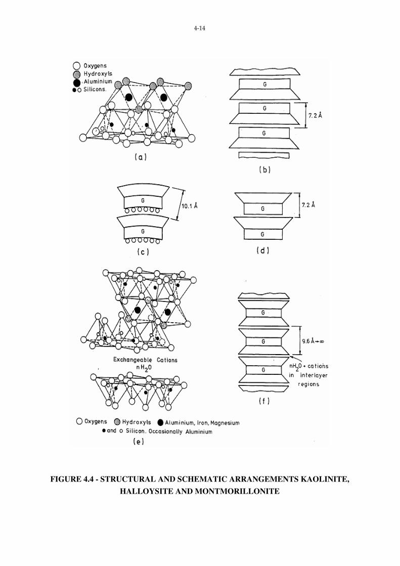
4.3.2 Clay Mineral Structures
(a) The 1:1 Mineral - Kaolinite
Two-thirds of the hydroxyls in one plane of the octahedral layer are replaced by
apical oxygens of the tetrahedral layer. The remaining OH ions are in the centres of hexagons
formed by oxygen ions at the apex of the silica tetrahedra. Because of a slight difference in
the cation spacing between the tetrahedral and octahedral layers, some distortion of the ideal
hexagonal tetrahedral network occurs. The vertical Si-0 bond is tilted slightly to fit the
overlying octahedral layers, resulting in a triclinic rather than monoclinic system.*
Bonding between the basal oxygens of one Kaolin unit and the hydroxyl associated
with the ‘top’ of the next is both Van der Waal’s and hydrogen. Thus a “tightly bound” stack
of 1:1 units can be constructed. This is shown diagrammatically in Fig. 4.4 (b).
Where the octahedral layer is Brucite a mineral of the Serpentine sub-group is
formed, whilst a mineral of the Kaolinite sub-group is formed if Gibbsite is the octahedral
layer.
If a monomolecular layer of water is present between the unit Kaolinite layers, a clay
mineral, Halloysite is formed.
As discussed previously, the b spacing for the 0 plane in the silica tetrahedra is
greater than the b spacing for the OH plane of the Gibbsite (8.93A˚ and 8.62A˚ respectively).
In Kaolin the OH spacings are stretched to match the silica sheet.
The interlayer water present in Halloysite reduces the bond between successive units,
and thus the stack tends to form tubes, as shown in Fig. 4.4 (c). For these tubes the c spacing
is 10.1A˚. Where the interlayer water is removed by drying the tubes tend to unroll: this
dehydration is irreversible, and can take place at temperatures as low as 60˚C.
(b) 2:1 Minerals
* CRYSTAL STRUCTURE
SYSTEM AXES AXIAL ANGLES
Triclinic
Monoclinic
a ≠ b ≠ c
a ≠ b ≠ c α ≠ β ≠ γ ≠ 90˚
α ≠ β = 90˚ γ = 90˚
Page 14
4-14
FIGURE 4.4 - STRUCTURAL AND SCHEMATIC ARRANGEMENTS KAOLINITE,
HALLOYSITE AND MONTMORILLONITE
Page 15
4-15
Included in this sub-group are the smectite minerals (montmorillonite) and illite
(hydrous mica). The structural arrangement is indicated in Fig. 4.4 (e).
The 2:1 minerals differ from the 1:1 through the addition of a second silica sheet
which sandwiches the octahedral layer. As in the case of the 1:1 minerals the hydroxyls of
the octahedral layer are replaced with apical oxygens from the silica sheets (see Fig. 4.4 (f).
Bonding between successive 2:1 units can vary from very weak Van der Waal’s
Bonds in the case of montmorillonite to the very strong bond arising from the interlayer
potassium ions in the case of the illites.
(c) 2:1:1 Minerals
If a brucite layer is located between adjacent 2:1 units the structure typical of
chlorites is obtained.
4.3.3 Source of Charge on a Clay Mineral
The formula/unit cell for a kaolinite is
(OH)8 Si4 Al4 010
whilst for a pyrophyllite (the prototype structure for montmorillonite) the formula/unit cell is
(OH)4 Si8 Al4 020
Both structures are electrically neutral. However both mineral types carry a charge:
the manner in which this charge deficiency is balanced, coupled with the bonding between
successive layers, is critically important to the explanation of behaviour.
A major source of charge imbalance is attributed to isomorphous substitution, ie. a
cation in the lattice is replaced by an ion of similar size, but (usually) carrying a lower charge.
For the four most common clay minerals this replacement has been suggested as:
1:1 Kaolinite Mg2+ for Al3+
2:1 Montmorillonite 1 Mg2+ for every 6th Al3+
Illite some Si4+ replaced by Al3+
Page 16
4-16
2:1:1 Chlorites Al3+ for Si4+
Al3+ for Mg2+ in the interlayer
The small charge carried by kaolinite has also been attributed to broken bonds
around particle edges which lead to unsatisifed positions of charge. Some work on the
position of exchange sites in kaolinite questioned this model, and suggested that (high) charge
deficiencies may arise from montmorillonite impurities present in the kaolinite, in addition to
isomorphous substitution. (McBride, 1976).
The charge imbalance associated with clay minerals is measured quantitatively by
the cation exchange capacity of the mineral.
To maintain charge equilibrium cations are attracted to the surface of a clay mineral
and are held in an exchangeable form on, or near, the surface by electrostatic forces. The
source of the exchangeable cations is from solution surrounding the clay particles, and as the
term “exchangeable” implies the ions associated with the colloidal clay particle are in
dynamic equilibrium with the ions of the surrounding solution.
Where the interlayer bond is strong, as for kaolins, exchangeable cations will be
adsorbed onto external surfaces. For 2:1 minerals, where successive units are weakly bonded,
the cation is adsorbed into the interlayer position. If the ion adsorbed into this interlayer
position is potassium a very strong bond between the potassium ion and adjacent 2:1 units is
formed - as for the mineral Illite. Chlorites reach charge neutrality through the positive
charge deficiency in the 2:1 layers being balanced by a positive charge excess in the interlayer
Brucite.
Of the three mineral structures discussed above, it is the weakly bonded 2:1 minerals
that produce most problems when subjected to change in environment.
These problems are associated with
(a) an expanding lattice, and
(b) particle size.
Page 17
4-17
4.3.4 The Influence of Water on Clay Mineral Behaviour
In a dry clay, adsorbed cations are bound tightly to the soil surface. The cations in
excess, and their associated anions are present as a salt precipitate. When this dry clay is
placed in water, the salts go into solution and the adsorbed cations are hydrated. The
negatively charge mineral surface and the distributed charge in the adjacent phase are together
known as the diffuse (or electrical) double layer. Factors which affect the nature and extent of
the double layer include:
(i) composition and concentration of the electrolyte solution,
(ii) density of charge on the surface of the particle,
(iii) valence of the cations,
(iv) dielectric constant of the medium, and
(v) temperature.
Mathematical theories concerning the double layer which include these factors are
well summarised in Lee (1968), and Mitchell (1977).
Previously it has been mentioned that clay particles can be of colloid size. In
solution, the particles will move in a random manner. If the attraction forces between
particles exceed forces of repulsion, the particles will increase in size - up to a stage where
gravitational forces will predominate and the particles will sediment out, i.e. the system
flocculates.
The forces controlling attraction and repulsion can be classified as:
(a) Independent of a system: eg. electrostatic or electromagnetic (Van der Waals)
or
(b) System Dependent: eg. electrostatic (electron or ion clouds) or ion hydration.
Electrostatic and electromagnetic forces both contribute to attraction, whilst electron
or ion clouds and ion hydration are forces of repulsion, with ion hydration being the major
repulsive force.
Page 18
4-18
Thus the behaviour of clay minerals in suspension can be controlled by changing the
environment. For the Cardinia Creek reservoir turbidity of the water was reduced by
introducing gypsum - the thickness of the double layer of the clay particles in suspension was
reduced, leading to forces of attraction exceeding repulsion forces. For this case the enlarged
particles settled out. (Grant et al, 1976).
Any factor which changes the “thickness” of the double layer will alter the
characteristics displayed by a clay soil. Two of the more important system variables are:
(a) Cation Valence: an increase in valence suppresses the concentration of the
solution between adjacent particles, and the potential between particles,
leading to a decrease in interparticle repulsion.
(b) Ion Size: the larger the ion size the thicker the layer required to accommodate
the necessary number of cations, hence the greater the repulsion.
Associated with both of these factors is the phenomenon that multi-valent ions are
adsorbed preferentially onto the mineral surface. For a given number of exchange sites, the
higher the valence the lower the number of ions required to satisfy charge neutrality and
hence the double layer is affected accordingly. This feature can be detected through very
simple soil tests
eg. Na Kaolinite wL = 53%, wp = 32%
Ca Kaolinite wL = 38%, wp = 27%
Since the difference between wL and wp is indicative of the compressibility of the soil we can
argue that a Na Kaolinite would be more compressible than a Ca Kaolinite.
When the double layer and mineral particle size are considered together it can be
argued that the smaller the particle (and hence the higher the specific surface) the larger the
amount of water that (with respect to the mass of dry soil) will be associated with the double
layer. This feature is of great importance when the swell of a soil, when wetted from a dry
condition, is considered. Of particular significance is the clay mineral montmorillonite: the
bonding between successive layers is weak and when an ion associated with this interlayer
position hydrates, the clay mineral stack will expand. Expansion associated with moisture
can cause structural failure in some lightly loaded structures.
Page 19
4-19
TABLE 4.3 - FLOW CHART: TESTS INVOLVED IN IDENTIFICATION OF SOIL
TYPES AND SOIL MINERALS (AFTER MITCHELL, 1977)
SOIL TO BE TESTED
Particle Size Pore Fluid Elec. Concentration PH Composition
Silt & Clay Sizes X-Ray D.T.A
Carbonates Oganic Matter Iron Oxides Exchange Complex
Sand & Gravel Sizes
Clay Size X-Ray D.T.A
Potash Glycol Adsorption Electron Micros
Gravel, Sand & Clay Sizes Mineral Identification Degree of Aggregate Extent of Weathering Particle Shape Angularity Texture
Page 20
4-20
4.4 IDENTIFICATION OF CLAY MINERALS
4.4.1 X-Ray Diffraction
The principle involved with estimating the spacing of crystal planes will not be
covered in these notes. It is assumed that the reader is familiar with the concept that, for a
given set of parallel planes, spaced d apart, the X-rays emitted from each plane will be in
phase when
nλ = 2d sin θ
where λ = wavelength of radiation
θ = angle of incidence of radiation to the planes
n = integer
X-Ray diffraction can be utilised to identify the (h, k, l) spacings of clay mineral
crystals.* hk spacings correspond to the a and b directions of the unit cell (except triclinic),
whilst l gives spacings normal to the plane along c (basal) spacings.
Since clay minerals have mostly layer-lattice structures, the basal spacing can be
used as a useful categorisation technique. The l spacing is also most susceptible to changes in
environment - a property which can be utilised as an aid to identification.
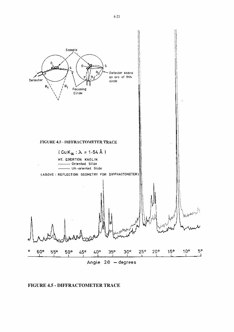
The most common identification technique involves the preparation of an oriented
sample, with detection of intensity of radiation made using a diffractometer - as shown in Fig.
4.5. Orientation of a specimen ensures that the basal plane lies parallel to the bed of the
mount - in this way, reflections from planes other than basal planes is suppressed. Fig. 4.5
shows traces for both an un-oriented and oriented sample. For the un-oriented sample
reflections from planes other than (0 0 l) are apparent.
To identify positively certain mineral groups, some pre-treatment is necessary. This
pre-treatment commonly includes heating to an elevated temperature and exposure to an
ethylene glycol atmosphere. Carroll (1970) recommends the preparation of three oriented
slides from the one soil suspension. Three traces can be obtained
* For a discussion on Crystal systems see, for example, Van Vlack, L.H., “Elements of Materials Science”, Addison Wesley.
Page 21
4-21
FIGURE 4.5 - DIFFRACTOMETER TRACE
Page 22
4-22
(a) normal,
(b) after glycolation (to detect any swelling tendency), and
(c) after heating (to determine changes in crystal structure).
If equation (1) is simplified to
λ = 2d sin θ
it can be seen that X-rays emitted from planes spaced d apart will be in phase. These
reflections are known as first-order basal reflections from the (001) plane. Note that for n = 2,
an apparent reflection from a plane d
2 is obtained. (The (002) plane). The intensity of
reflection from these planes, and their spacings can be used to characterise the clay mineral.
Table 4.4 summarises X-ray characteristics for certain clay minerals.
Having obtained a diffraction pattern (diffractogram), as shown in Fig. 4.5, the
diffractogram can be compared with a set of “in-house” standards, obtained from minerals
with a known composition or structure, or the d spacings obtained can be compared with d
spacings of standard clay minerals as recorded in the ASTM Power Diffraction File. In this
way, some indication can be gained of the minerals predominant in the unknown sample.
Example: Consider the trace for the oriented specimen (Fig. 4.5). The three most intense
peaks occur at
I1 : 2θ = 12.4˚
I2 : 2θ = 25.0˚
I3 : 2θ = 37.8˚
Converting these 2θ values to d spacings via
d = λ
2d sinθ =
1.54
2 sinθ ˚A
we have:
I1 : d = 7.13˚A
I2 : d = 3.56˚A
I3 : d = 2.38˚A
Page 23
4-23
Within experimental tolerances, these correspond to the 7.15˚A (001), 3.57˚A (002)
for Kaolinite (Carroll, 1970).
TABLE 4.4
X-Ray Identification of Selected Clay Minerals (2µµµµm) Oriented Mount
(After Carroll, 1970)
Mineral Basal Spacings (001) Glycolation Effect (1
hr, 60_C)
Heating Effect - 1 hr
Kaolinite 7.15˚A (001) : 3.57˚A
(002)
No change Becomes amorphous
550-600˚C
Kaolinite-
disordered
7.15˚A (001) Broad:
3.75˚A (002) Broad
No change As above - at lower
temperature
Halloysite 4H20
2H20
10˚A (001) Broad
7.2˚A (001) Broad
No change
No change
Dehydrates to 2H20
form at 110˚C
Dehydrates at 125-
150˚C
Illite 10˚A (002) Broad No change Amorphous 560-590˚C
(001) Enhanced on
heating
Smectite
(Montmorillonite)
15˚A (001) and
integral series of basal
spacings
(001) expands to
17˚A
At 300˚C (001)
Becomes 9A
Mg Chlorite 14˚A (001) and
integral series of basal
spacings
No change (001) increases in
intensity : < 800˚C
Mass Loss - No
Structural change
We are further justified in predicting Kaolinite because of the very intense (001) and
(002) reflections as compared with the (003) and (004). (004) at 2θ = 51.1˚)
Estimating the relative proportions of various clay minerals present in an unknown
soil sample using X-ray diffraction is extremely difficult. There can be differences in the
crystallinity of each component, varying degrees of hydration, variations in the distribution of
the components in the mix, and other factors which act against accurate assessment. Where
conditions are favourable, measurements of the area under the peaks at the principal spacing
of each component can be compared to standards and some estimation of the relative
Page 24
4-24
proportions made. Carroll (1970) discussed procedures adopted, and limitations, in some
detail.
X-ray diffraction is an extremely powerful, and most definitive method for
identifying clay minerals. However, a complete identification will usually require additional
testing. The range of testing is discussed in subsequent sections.
4.4.2 Thermal Analysis
(a) Differential Thermal Analysis
The application of Differential Thermal Analysis (DTA) to the identification of soils
used in engineering applications was reported extensively by Lambe (1952). The technique
has as its greatest advantage simplicity and rapidity. It is claimed that the order of accuracy
for the determination of constituent minerals is of the same order as X-ray diffraction i.e. 5-
10%. A schematic arrangement of the equipment involved is as shown in Fig. 4.6.
As a sample is heated, reactions will occur. If the heat absorbed or emitted during
these reactions is compared to characteristics displayed by an inert material (usually calcined
alumina) undergoing the same temperature change, a trace is obtained of differential thermal
response versus temperature. (see Fig. 4.7).
If the sample absorbs heat with respect to the standard, a trough occurs in the trace
(an endothermic reaction). Where the sample evolves heat compared to the standard, a peak
occurs (an exothermic reaction). A heating rate of 10˚C/min is usually adopted through a
range up to 1000˚C.
Important reactions include:
(a) Dehydration (Endothermic)
(i) adsorbed water (driven off between 100-300˚C)
(ii) crystal lattice water (the (OH) ions) - termed dehydroxylation.
Dehydroxylation causes a complete destruction of the mineral structure.
Page 25
4-25
Figure 4.6 Essential Features- D.T.A. Apparatus
RECORDING DEVICE
FURNACE RECORDER
FURNACE CONTROLLER
T(X-AXIS)
∆T(Y-AXIS)
DIFFERENTIAL THERMOCOUPLE
FURNACE
INERT MATERIAL
SAMPLE
Page 26
4-26
FIGURE 4.7 - THERMOGRAMS OF VARIOUS CLAY MINERALS
(AFTER LAMBE, 1952)
Page 27
4-27
(b) Exothermic Reactions
(i) Crystallisation: new crystals may form from amorphous materials, or
from old crystals destroyed at lower temperatures,
(ii) Oxidation: e.g. or organic matter between 250-450_C.
Lambe (1952) published a large variety of DTA traces performed on soils drawn
from many parts of the world.
MacKenzie (1957) includes detailed discussion on the interpretation of traces and the
quantitative estimation of proportions of components present in a sample.
Fig. 4.7 shows traces for four soils, taken from Lambe (1952). Note that the
Halloysite is distinguished from the Kaolinite principally by the relatively large endotherm
between 100-200˚C, corresponding to the loss of adsorbed water.
(b) Thermogravimetric Analysis
Thermogravimetric Analysis (TGA) involves a measurement of the change in mass
of a sample as it is heated.
Changes in mass of a sample can result from:
(i) Loss of adsorbed water (t < 200˚C)
(ii) Removal of lattice water (t < 800˚C)
(iii) Loss of C02 from carbonates
(iv) Removal of volatile components from non-clay mineral constituents in the
sample
(v) Oxidation, eg. Ferrous to Ferric Iron can produce an increase in mass of the
sample.
Where it is important to minimise the mass change caused by non-clay components,
pre-treatment of the sample is often performed, eg. removal of carbonates can be affected by
repeated treatment with hydrochloric acid.
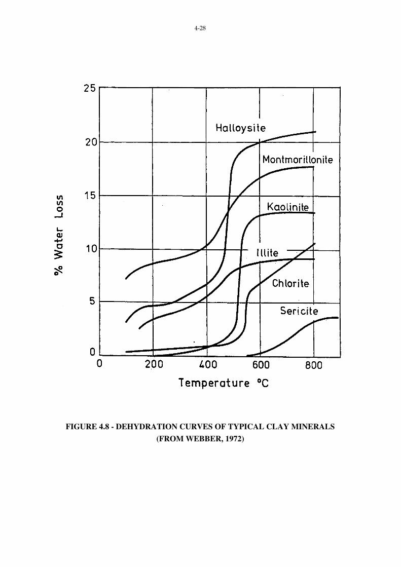
Typical dehydration curves for various clay minerals are shown in Fig. 4.8. An
extensive tabulation of dehydration data can be found in Mielenz et. al. (1954).
Page 28
4-28
FIGURE 4.8 - DEHYDRATION CURVES OF TYPICAL CLAY MINERALS
(FROM WEBBER, 1972)
Page 29
4-29
4.4.3 Specific Surface
The assumption underlying the determination of specific surface is that when
exposed to an environment of glycol, the clay layer will adsorb a monomoledular layer of the
glycol. Under some conditions this assumption is not true.
Clay layers will adsorb polar molecules from the liquid as well as the gaseous phase.
Either ethylene glycol or glycerol is used as the environment. The test procedure involves
determining the dry mass of sample, exposure in a glycol atmosphere and determination of
mass of sample plus glycol retailed.
Specific Surface (m2/g) = Mg
(Ms x 0.00031)
Mg = mass of glycol retained
Ms = mass of dried sample
0.00031 = mass of glycol (in grams) required to form a monomoledular layer on
a surface area of 1m2.
4.4.4 Cation Exchange Capacity
Cation exchange capacity (CEC) measures those ions bound loosely to the mineral
surface by charge deficiency in the particular crystal lattice. One procedure used to determine
CEC involves pre-heating the sample to remove soluble salts and organic matter, and then
saturating potential sites with CaC12. Sodium acetate is used to replace the Ca2+ which is
then determined in the washing solution by titration. For a more complete description see
Jackson (1958).
4.4.5 Chemical Analysis
Chemical analysis gives composition in terms of elements - generally expressed as
oxides on a percentage basis. As well as providing information on composition, a chemical
analysis can be used for predicting performance at high temperature, (for burned clay
products). Where K20 is present in a clay mineral sample, the proportion can be used to
determine the percentage illite present.
Table 4.5 gives typical values for glycol retention (specific surface), CEC, and K20
for selected clay minerals.
Page 30
4-30
MINERAL CLYCOL
RETENTION (mg/g)
CEC (meg/100g) K20 (%)
Kaolinite 16 3 0
Halloysite 4H20 60 12 0
Halloysite 2H20 35 12 0
Illite 60 25 8-10
Montmorillonite 300 85 0
Chlorite 30 40 0
TABLE 4.5 SELECTED CHARACTERISTICS OF CERTAIN CLAY MINERALS (from
Mitchell, J.K., “Fundamentals of Soil Behaviour” Wiley, 1976)
4.4.6 Electron Microscopy
An electron beam performs a similar function to a light beam, but because the
wavelength of the electron beam <<< the wavelength of visible light the potential resolving
power of an electron microscope is much greater than that for a light microscope.
Magnifications of 100 000+ can be achieved readily.
The transmission electron microscope (TEM), as its name implies relies on
transmitting an electron beam through the sample. Since the penetrating power of an electron
beam is low at the potential differences commonly employed, very thin specimens must be
used.
For TEM work a replica is often made of the specimen surface. A replica is a thin
film which is transparent to electrons. The replica, which can be used to great effect in
textural studies will produce a negative impression of the soil surface - to overcome this a
second replica is often taken, using the original as a base.
A scanning electron microscope (SEM) utilises a reflection geometry. An electron
beam is scanned over the soil surface and the secondary electrons emitted are collected and
displayed on a cathode ray tube. Whilst the resolution of the SEM is not as good as the TEM
a greater depth of field is obtained - particularly useful for morphological studies.
Sample preparation for the SEM is relatively simple (although special techniques
have to be used to dry the specimen and prepare a “clean” surface). Since a clay surface is
non-conducting a thin layer of gold or gold alloy is plated onto the surface prior to
examination.
Page 32
4-32
Electron microscopy has been used for textural and morphological studies of clay
minerals, examination of sample disturbance and examination of sheared zones. (See for
example “Proceedings of the International Symposium on Soil Structures”, Gothenburg,
1973, Morgenstern and Tchalenko (1967).
4.4.7 Field Identification
In some cases the presence of a soil type that may cause problems can be detected
during a field inspection. Depending on the magnitude of the project, a field identification
may provide an adequate categorisation of clay mineral type. Ingles and Metcalf (1972) have
produced a simple identification table (Table 1.6) which utilised features such as colour of
retained water, surface relief, rock type, erosion and soil profile as an aid to mineral
identification. Emerson (1967) has devised a simple field (or laboratory test) which can be
used to aid further the identification of predominant clay minerals.
4.5 APPLICATIONS TO ENGINEERING PRACTICE
An understanding of the mineralogy associated with clay soils can be useful as an aid
to the complete explanation of observed behaviour. The following section gives examples of
such behaviour.
4.5.1 Residential (Lightly Loaded) Slabs-on-ground
When a clay suffers a seasonal moisture change, movement associated with soil
swell and shrinkage will occur. This movement will vary with depth and climate. Factors
which influence seasonal movement of clay soils are:
(i) Clay mineralogy
(ii) Soil profile,
(iii) Site drainage,
(iv) Climate,
(v) Superimposed loading, and
(vi) Location and type of trees.
Page 33
4-33
TABLE 4.6 FIELD IDENTIFICATION OF SOIL MINERALOGY
(After Ingles & Metcalf (1972)
Turbid Water - Yellow Brown/Red Brown:
Montmorillonites Illites
Clear Water: Ca, Mg, Fe Rich soils, highly
acid soils
Clear Water with Bluish Cast: Non-Saline
Kaolinites
Erosion Gullies and/or field tunnelling:
Montmorillonites
(Mild gullying): Kaolinite
Landslips: Kaolinites, Chlorites
Country rock type - granitic: Kaolinites,
Mica
- poorly drained basaltic:
Montmorillonites
- well drained basaltic: Kaolinites
- Mudstones: Montmorillonites, Illite
Soil profile - Mottled
Red/orange/white: Kaolinite
- Yellow/orange/grey or Med.-Dark grey,
Black: Montmorillonites
- Brown and Red-brown clays: illite, some
Montmorillonite
- white and lt-grey clays: Kaolinites
Soil Profile
- Extensively cracked; wide, deep and
closely spaced (50-60mm): Ca Rich
Illites Montmorillonites
- open textured, appreciable clay:
carbonates or kaolin (Never
Montmorillonite seldom illite)
- “wormy” appearance on exposed
weathered profile: Montmorillonite + soil
salinity
- relatively thin strongly bleached horizon
near soil surface (up to 600mm from top)
above bleach: fine silt
below bleach: dispersive soil
Page 34
4-34
For engineering applications, the predominant clay mineral type is rarely determined
directly - mineralogy is inferred from other classification tests eg. Linear shrinkage and
plasticity index. Clays where kaolinite is present as the predominant mineral will yield low
values of Linear shrinkage and Atterberg Limits, whilst the expansive montmorillonite will
result in correspondingly much higher values.
Frequently physical characteristics will minimise any tendency for soil movement.
A layer of non-expansive soil over an expansive layer will minimise any swell. Excluding
climate, other factors which reduce swelling include the thickness of the expansive layer and
the drainage conditions of the site.
Extensive damage to lightly loaded structures has been caused by moisture loss in
the soil beneath foundations caused by trees taking water in through their root systems.
Providing that the moisture conditions beneath a lightly loaded structure are
maintained constant, no movement, swelling or shrinkage, of the soil will occur.
4.5.2 Dispersive Soils
It has been mentioned earlier that where forces of attraction between clay mineral
particles exceed repulsion forces, a flocculated structure exists. If any change of environment
occurs to change this relationship the clay mineral stacks can disintegrate and individual
particles will go into suspension. A soil which follows this behaviour is known as dispersive.
Where individual particles are very small, low seepage velocities will carry away particles in
suspension and a loss of material will ensue. Such a loss can lead to failure of earthern
structures eg. earthern channels or dams.
The mechanism which controls the deflocculation of a clay soil is associated with the
ionic equilibrium between the counter ions (cations) associated with the clay surface and the
concentration of ions in the bulk water phase. A disequilibrium can lead to structural failure.
Equilibrium can be upset when the ionic concentration of impounded water (as in the
case of a dam) is significantly different to that for the “natural” soil water. Since rain water
has a relatively low ionic concentration a soil prone to deflocculation can cause major
problems in earth dams.
It is not intended to discuss the failure mechanism in detail. For further information
on theory and applications see Ingles and Metcalf (1972).
Page 35
4-35
4.5.3 Aggregates
To assist in the interpretation of the long-term behaviour of basalt aggregates used in
concrete and road pavements, research projects have been conducted.
The basalt aggregate from some quarries includes material in which the primary rock
forming minerals have been altered by weathering. The resulting secondary minerals can
include expanding clay minerals.
To avoid any potential disruption to cured concrete or road bases a limit is set on the
proportion of secondary minerals in the aggregate: in the case of concrete aggregate, 25%,
whilst for road aggregate 20%.
Page 36
4-36
REFERENCES
Bohor, B.F. and Hughes, R.E., “Scanning Electron Microscopy of Clays and Clay Minerals”
Clays and Clay Minerals, Vol. 19, No. 1, 1971.
Brown, G. (Ed), The X-ray Identification and Crystal Structures of Clay Minerals”, The
mineralogical Society of London, 1961.
Carroll, D., “Clay Minerals: A Guide to Their X-ray Identification, The Geol. Soc. of
America, Special paper 126, 1970.
Cole, W.F. and Beresford, F.D., “Evaluation of Basalt ... as an Aggregate for Concrete”, Proc.
ARRB., Vol. B, Pt. 3, Perth 1976.
Cole, W.F., Lancucki, C.J., and Nickson, N.M., “Ceramic Clays and Shales from the
Melbourne Area” CSIRO, Div. Bldg. Research Tech. Paper no. 22. 1968.
Currey, D. “Extension course on Engineering Geology” Australian Geomechanics Society,
Vic. Group, Melb. 1968.
Emerson, W.W. “A Classification of Soil Aggregates Based on their Coherence in Water”.
Aust. Journal of Soil Research Vol. 5, 1967.
Gillot, J.E., “Clay in Engineering Geology, Elsevier, Amsterdam 296p, 1968.
Grant, K., Ingles, O.G., Lawrence, I.A. and Sommerville, P.J., “Protecting a Dispersive Soil
by Water Treatment”, ASTM, STP, 623, 1976.
Grim, R.E., “Clay Mineralogy”, 2nd Ed, McGraw Hill, NY, 596p 1968.
Holland, J.E., Washusen, J. and Cameron, D., “Ground Movement Information for Melbourne
Soils...”, Australian Geomechanics Society, Vic. Group, Symposium on Insitu Testing
Testing for Design Parameters, Melb. Nov. 1975.
Ingles, O.G. and Metcalf, J.B., “Soil stabilization”, Butterworths, Sydney, 366p, 1972.
Jackson, J.L., “Soil Chemical Analysis”, Prentice hall, Englewood Cliffs New Jersey. 498 pp.
1958.
Page 37
4-37
Kirkpatrick, W.M. and Rennie, I.A., “Clay Structure in Laboratory Prepared Samples”, Proc.
International Symposium on Soil Structure, pp. 103-112, Gothenburg, 1973.
Lambe, T.W., “Differential Thermal Analysis”, Proc. H.R.B. Vol. 31, pp. 620-641, 1952.
Lambe, T.W. and Whitman, R.V., “Soil Mechanics”, Wiley, New York, 553p, 1969.
Lee, I.K. (Ed) “Soil Mechanics - Selected Topics” (In particular Ch. 1) Butterworths, London,
1968.
McBride, M.B., “Origin and Position of Exchange Sites in Kaolinite”, Clays and Clay
Minerals, Vol. 24, No. 2, 1976.
MacKenzie, R.D. (Ed) “The Differential Thermal Investigation of Clays” Min. Soc., London,
456 pp. 1957.
Mielenz, R.C., Schieltz, N.C., and King, M.E., “Thermogravimetric Analysis of Clay and
Clay-Like Minerals. Proc. Nat. Conf. Clays and Clay Minerals, 1953.
Mitchell, J.K., “Fundamentals of Soil Behaviour”, Wiley, New York, 422p, 1976.
Morgenstern, N.R. and Tchalenko, J.S., “Microscopic Studies in kaolin Subjected to Direct
Shear”, geotechnique, Vol. 17, No. 4, 1967.
Neilson, J.L., “The Silvrian Rocks of the Melbourne Region...”, Australian Geomechanics
Society, Vic. Group, Workshop on Engineering Properties of Melbourne Mudstone, Melb.,
April 1977.
Webber, J.R., “A Comparison of the Results of the Washington Degradation Test...”, Country
Roads Board of Victoria Research Memorandum No. 16, 1972.


![aq s;Mbpur;,m - astrojyoti.com · v≤xœ ¨v;c Í,u„v;vihto r;j 'StSy tCz;pk;r,m (b[˜,o m;ns" p ]o n;rdo n;m yo mu uin" 9 b[˜lok É m uneStSy iv„, ulok É ivx eWt" sUyRlok](https://static.documents.pub/doc/80x56/5acf16447f8b9a56098c9ebb/aq-smbpurm-xoe-vc-uvvihto-rj-stsy-tczpkrm-bo-mns-p-o-nrdo.jpg)


![aq s;Mbpur;,m · v≤xœ ¨v;c Í,u„v;vihto r;j 'StSy tCz;pk;r,m (b[˜,o m;ns" p ]o n;rdo n;m yo mu uin" 9 b[˜lok É m uneStSy iv„, ulok É ivx eWt" sUyRlok É c stt ' ®{lok](https://static.documents.pub/doc/80x56/5e6bfa10701c741c420c1643/aq-smbpurm-vax-vc-uavvihto-rj-stsy-tczpkrm-boeo-mns.jpg)

