68
4" Submersible Pumps INSTALLATION, OPERATION AND MAINTENANCE MANUAL INSTRUCTION MANUAL IM096

4" Submersible PumpsINSTALLATION, OPERATION AND MAINTENANCE MANUAL
INSTRUCTION MANUALIM096

2
Table of Contents
SUBJECT PAGESafety Instructions ................... 3 & 4Pump Protection Devices .................4Installation Checklist .......................51.0 Typical Installations ...................62.0 Piping and Tank .........................73.0 Wire Sizing, Splicing and Power Supply ...............................94.0 Wiring the Controls and Switch .........................................95.0 Starting the Pump ....................126.0 Paperwork and IOM ...............12CentriPro 4" 1 Ph Motor Data ......13Single Phase Wire Sizing Charts ....14PumpSaver Schematics ..................14Three Phase Motor Data ...............15Three Phase Motor Electrical Data ...........................16Three Phase Motor Wire Chart ................................17Resistance and Generator Data .....18Wiring Diagrams ................. 19 & 20Three Phase Starters ......................21Troubleshooting .............................22Limited Warranty ..........................66
Owner’s Information
Pump Model #:
Pump Serial #:
Motor Model #:
Motor Serial #:
Dealer:
Dealer Telephone:
Purchase Date:
Installation Date:
Volts:
Amps:
Owner’s Information Table of Contents

3
All electrical work must be performed by a qualified technician. Always follow the National Electrical Code (NEC),
or the Canadian Electrical Code, as well as all local, state and provincial codes. Code questions should be directed to your local electrical inspector. Failure to follow electrical codes and OSHA safety standards may result in personal injury or equipment damage. Failure to follow manufacturer’s installation instructions may result in electrical shock, fire hazard, personal injury or death, damaged equipment, provide unsatisfactory performance, and may void manufacturer’s warranty.
Standard units are not designed for use in swimming pools, open bodies of water, hazardous liquids, or where flammable
gases exist. Well must be vented per local codes. See specific pump catalog bulletins or pump nameplate for all agency Listings.
Disconnect and lockout electrical power before installing or servicing any electrical equipment. Many pumps are equipped
with automatic thermal overload protection which may allow an overheated pump to restart unexpectedly.
Never over pressurize the tank, piping or system to a pressure higher than the tank's maximum pressure rating. This will
damage the tank, voids the warranty and may create a serious hazard.Protect tanks from excessive moisture and spray as it will cause the tank to rust and may create a hazard. See tank warning
labels and IOM for more information.
WARNING
WARNING
WARNING
Important notice: Read safety instructions before proceeding with any wiring
SAFETY INSTRUCTIONS
TO AVOID SERIOUS OR FATAL PERSONAL INJURY OR MAJOR PROPERTY DAMAGE, READ AND FOLLOW ALL SAFETY INSTRUCTIONS IN MANUAL AND ON PUMP.THIS MANUAL IS INTENDED TO ASSIST IN THE INSTALLATION AND OPERATION OF THIS UNIT AND MUST BE KEPT WITH THE PUMP.
This is a SAFETY ALERT SYMBOL. When you see this symbol on the pump or in the manual, look for one of the following signal words and be alert to the potential for personal injury or property damage.Warns of hazards that WILL cause serious personal injury, death or major property damage.Warns of hazards that CAN cause serious personal injury, death or major property damage.Warns of hazards that CAN cause personal injury or property damage.
NOTICE: INDICATES SPECIAL INSTRUCTIONS WHICH ARE VERY IMPORTANT AND MUST BE FOLLOWED.THOROUGHLY REVIEW ALL INSTRUCTIONS AND WARNINGS PRIOR TO PERFORMING ANY WORK ON THIS PUMP.MAINTAIN ALL SAFETY DECALS.
DANGER
CAUTION
WARNING
WARNING
WARNING

4
CAUTION
WARNING
WARNING
WARNING
WARNING
WARNING
WARNING
WARNING
DANGER
WARNING
CAUTION
SAFETY INSTRUCTIONS (continued)
Do not lift, carry or hang pump by the electrical cables. Damage to the electrical cables can cause shock, burns or death.Use only stranded copper wire to pump/motor and ground. The ground wire must be at least as large as the power supply wires. Wires should be color coded for ease of maintenance and troubleshooting.Install wire and ground according to the National Electrical Code (NEC), or the Canadian Electrical Code, as well as all local, state and provincial codes.Install an all leg disconnect switch where required by code.The electrical supply voltage and phase must match all equip-ment requirements. Incorrect voltage or phase can cause fire, motor and control damage, and voids the warranty.All splices must be waterproof. If using splice kits follow manufacturer’s instructions.Select the correct type and NEMA grade junction box for the application and location. The junction box must insure dry, safe wiring connections.All motors require a minimum 5' submergence for proper refill check valve operation.Failure to permanently ground the pump, motor and controls before connecting to power can cause shock, burns or death.All three phase (3Ø) controls for submersible pumps must provide Class 10, quick-trip, overload protection. 4" motors ≥ 2 HP require a minimum flow rate of .25 ft/sec. or 7.62 cm/sec. past the motor for proper motor cooling. The following are the minimum flows in GPM per well diameter required for cooling: 1.2 GPM/4", 7 GPM/5", 13 GPM/6", 20 GPM/7", 30 GPM/8" or 50 GPM in a 10" well. Pumps ≥ 2 HP installed in large tanks should be installed in a flow inducer sleeve to create the needed cooling flow or veloc-ity past the motor.This pump has been evaluated for use with Water Only.
CAUTION
CAUTION
PUMP PROTECTIONWe recommend using SymCom’s PumpSaver to protect the system from low water, rapid cycling, high/low voltage, dead heading/flow restriction and overcurrent.

5
INSTALLATION CHECK LIST• Enter the pump and motor information and other requested data on the front
of this manual.• Inspect all components for shipping damage, report damage to the distributor
immediately.• Verify that motor HP and pump HP match.• Match power supply voltage and phase to motor and control specifications.• Select a dry, shaded location in which to mount the controls.• Make all underwater and underground splices with waterproof splice
connections.• Hold the pump at the discharge head when installing threaded pipe or an
adapter fitting as most pumps have left hand threads which will be loosened if you hold the pump anyplace except the discharge head.
• Check all plumbing connections to insure they are tight and sealed with Teflon tape.
• Verify that the pipe pressure rating is higher than pump shut-off pressure.• Install a pressure relief valve on any system capable of creating over 75 PSI.
The system pressure cannot exceed the tank's maximum pressure rating.• Locating the tank and controls in an area protected from rain, spray and
other environmental factors may prolong their useful life. Especially in areas with acid rain and saline water.
• Locate the pressure switch within 4' of the pressure tank to prevent switch chatter.
• Adjust tank pre-charge to 2 PSI below the system cut-in pressure setting, ex. 28 on a 30/50 system.
• Set the pump 10' above the well bottom to keep above sediment and debris.• Insure that main power is disconnected, turned OFF, before wiring any com-
ponents.• Wiring should be performed only by qualified technicians.• Wiring and Grounding must be in compliance with national and local codes.• Restrict the flow with a ball or globe valve, 1/3 open, before starting pump
for first time.• Open a faucet or discharge valve on start-up to keep dirty water from enter-
ing the tank.• Turn main breaker or disconnect ON.• Run through several on/off cycles to verify proper switch operation.• Check amps and enter the data on the front of this manual.• Leave the manual with the owner or at the job site.
6
Figure 1
Figure 2
Protected Power SupplyDisconnect Switch
Control Box Pressure Gauge To House
Piping
Shut-off Valve
UnionDrain Tap
Pressure Relief Valve
Air Escape ControlPressure Switch
Line Check Valve with Snifter
Union
Pitless Adapter
Drain and Y FittingApproximate Drain Fitting Setting
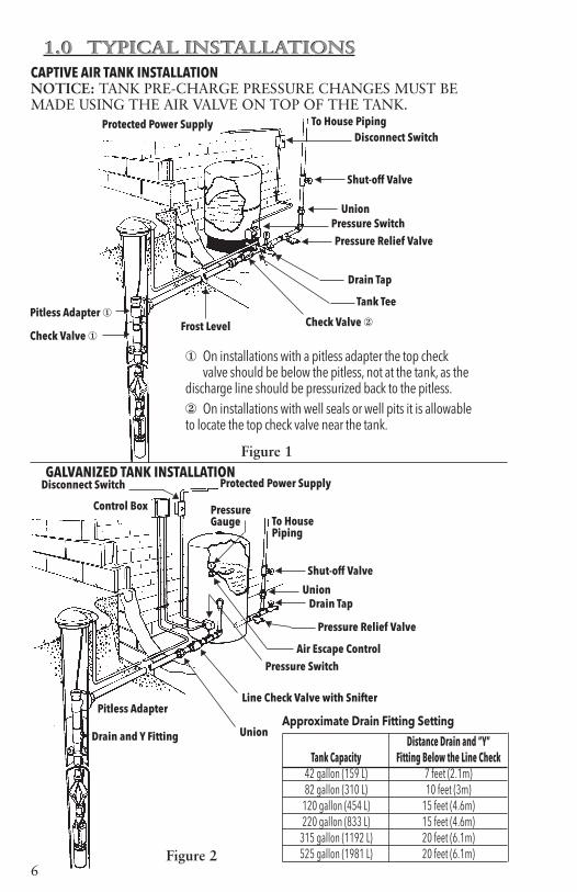
Distance Drain and “Y” Tank Capacity Fitting Below the Line Check 42 gallon (159 L) 7 feet (2.1m) 82 gallon (310 L) 10 feet (3m) 120 gallon (454 L) 15 feet (4.6m) 220 gallon (833 L) 15 feet (4.6m) 315 gallon (1192 L) 20 feet (6.1m) 525 gallon (1981 L) 20 feet (6.1m)
Protected Power Supply To House PipingDisconnect Switch
Shut-off Valve
Union
Pressure Relief Valve
Drain Tap
Tank Tee
Check Valve ②Frost Level
GALVANIZED TANK INSTALLATION
1.0 TYPICAL INSTALLATIONS 1.0 TYPICAL INSTALLATIONS
Check Valve ①
Pitless Adapter ①
Pressure Switch
① On installations with a pitless adapter the top check valve should be below the pitless, not at the tank, as the discharge line should be pressurized back to the pitless.② On installations with well seals or well pits it is allowable to locate the top check valve near the tank.
CAPTIVE AIR TANK INSTALLATIONNOTICE: TANK PRE-CHARGE PRESSURE CHANGES MUST BE MADE USING THE AIR VALVE ON TOP OF THE TANK.

7
2.0 PIPING
Notice: Most 4" submersibles have left-hand discharge head threads, hold the pump only at the “discharge head” when installing fittings or threaded pipe.
2.1 GeneralThe pump discharge piping should be sized for efficient pump operation. Use the Friction Loss Tables to calculate total
dynamic head using different pipe sizes. As a rule of thumb, use 1" for up to 10 gpm, 1¼" for up to 30 gpm, 1½" for up to 45 gpm, and 2" for up to 80 gpm. In the case of long pipe runs it is best to increase pipe size. Some pumps are capable of very high discharge pressures, please select pipe accordingly. Consult with your pipe supplier to determine the best type of pipe for each installation.
2.2 Pressure Tank, Pressure Switch and Pressure Relief ValveSelect a dry location in which the ambient temper-ature is always above 34º F (1º C) in which to install the tank, pressure switch,
and pressure relief valve. The tank should be located in an area where a leak will not damage property.The pressure switch should be located at the tank cross tee and never more than 4' from the tank. Locating the switch more than 4' from the tank will cause switch chatter.Do not install valves, filters, or high loss fittings between the switch and the tank(s) as switch chatter may result. As an example, a 1¼" spring check valve has friction loss equal to 12' of pipe, placing the valve between
the pressure switch and the pressure tank is the same as moving the pres-sure switch 12' away from the tank. It will create switch chatter.On multiple tank installations the switch should be as close to the cen-ter of the tanks as possible. Multiple tank installations should have a mani-fold pipe at least 1½ times the size of the supply pipe from the pump. This will reduce the Friction Head in the manifold and reduce the possibility of switch chatter. Pressure relief valves are required on any system that is capable of producing 100 psi or 230' TDH. If blow-off may damage property, connect a drain line to the pressure relief valve and run it to a suitable drain.
2.3 Adjusting Tank Pre-ChargeInsure that the tank is empty of water. Use a high quality pressure gauge to check the tank pre-charge pressure. The pressure should be 2 psi below the pump cut-in pressure. As an example, a 30-50 psi system would use a tank pre-charge of 28 psi.
2.4 Discharge Pipe Note: Most discharge heads are threaded into the casing with left-hand threads. Hold the pump only at the discharge head when installing fittings. Failure to hold the discharge head will loosen it and pump damage will result on start-up. If your pipe requires an adapter we strongly recommend using stain-less steel. Galvanized fittings or pipe should never be connected directly to a stainless steel discharge head as galvanic corrosion may occur. Plastic or brass pumps can use any material for this connection. Barb type connectors should always be double clamped.
Hazardous pressure cancause personal injury orproperty damage.
CAUTION
2.0 PIPING
Do not install tank whereit will be subjected tospray from irrigationsystems. Exposure to suchspray could result incorrosion of the tank,eventually leading to anexplosion which can causeproperty damage, seriouspersonal injury or death.
DANGER
8
The pump discharge head has a loop for attaching a safety cable. The use of a safety cable is recommended when using poly pipe as the pipe stretches when under pressure and filled with water.
2.5 Installing Pump in WellIf using a torque arrestor, install it per the manufacturer’s installation instructions. Consult the seller for information on torque arrestors and for installation instructions.Connect the discharge pipe to the discharge head or adapter. Barb style connectors should be double clamped. Install the pump into the well using a pitless adapter or similar device at the wellhead. Consult the fitting manufacturer or pitless supplier for specific installation instructions.
Using waterproof electrical tape, fasten the wires to the drop pipe at 10' intervals. Pump suppliers also sell clip-on style wire connectors that attach to the drop pipe.
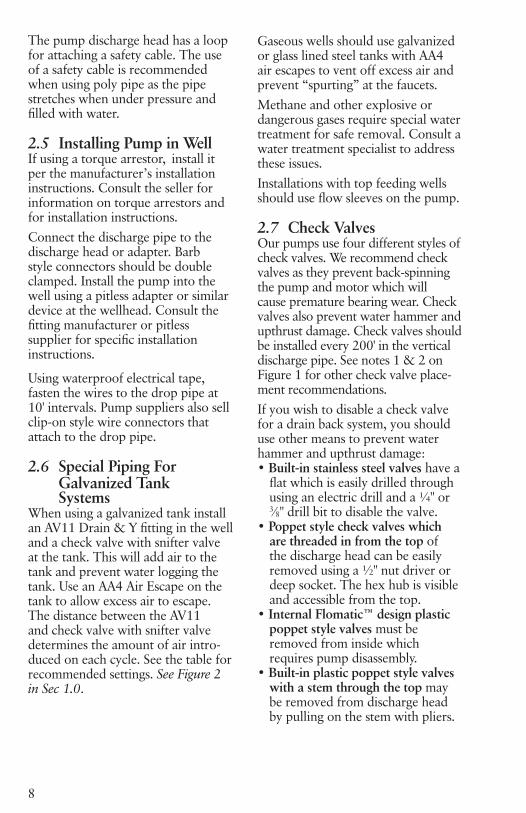
2.6 Special Piping For Galvanized Tank SystemsWhen using a galvanized tank install an AV11 Drain & Y fitting in the well and a check valve with snifter valve at the tank. This will add air to the tank and prevent water logging the tank. Use an AA4 Air Escape on the tank to allow excess air to escape. The distance between the AV11 and check valve with snifter valve determines the amount of air intro-duced on each cycle. See the table for recommended settings. See Figure 2 in Sec 1.0.
Gaseous wells should use galvanized or glass lined steel tanks with AA4 air escapes to vent off excess air and prevent “spurting” at the faucets. Methane and other explosive or dangerous gases require special water treatment for safe removal. Consult a water treatment specialist to address these issues. Installations with top feeding wells should use flow sleeves on the pump.
2.7 Check ValvesOur pumps use four different styles of check valves. We recommend check valves as they prevent back-spinning the pump and motor which will cause premature bearing wear. Check valves also prevent water hammer and upthrust damage. Check valves should be installed every 200' in the vertical discharge pipe. See notes 1 & 2 on Figure 1 for other check valve place-ment recommendations.If you wish to disable a check valve for a drain back system, you should use other means to prevent water hammer and upthrust damage:• Built-in stainless steel valves have a
flat which is easily drilled through using an electric drill and a ¼" or 3⁄8" drill bit to disable the valve.
• Poppet style check valves which are threaded in from the top of the discharge head can be easily removed using a ½" nut driver or deep socket. The hex hub is visible and accessible from the top.
• Internal Flomatic™ design plastic poppet style valves must be removed from inside which requires pump disassembly.
• Built-in plastic poppet style valves with a stem through the top may be removed from discharge head by pulling on the stem with pliers.

9
3.0 WIRE SIZING, SPLICING and POWER SUPPLY
Always follow the National Electric Code (N.E.C.), Canadian Electrical Code, and any state, provincial, or local codes.We suggest using only copper wire. Size wire from the charts found in the Technical Data section of this manual, MAID manual, or an N.E.C. (National Electric Code) code book. If discrepancies exist the N.E.C. book takes precedence over a manufacturer’s recommendations.
3.1 Splicing Wire to Motor LeadsWhen the drop cable must be spliced or connected to the motor lead, it is necessary that the splice be water-tight. The splice can be done with heat shrink kits or waterproof tape.
A. Heat Shrink Splice InstructionsTo use a typical heat shrink kit: strip ½" from the motor wires and drop cable wires; it is best to stagger the splices. Place the heat shrink tubes on the wires. Place the crimps on the wires and crimp the ends. Slide the heat shrink tubes over the crimps and heat from the center outward. The sealant and adhesive will ooze out the ends when the tube shrinks. The tube, crimps, sealant, and adhesive create a very strong, watertight seal.
B. Taped Splice InstructionsA) Strip individual conductor of insulation only as far as necessary to provide room for a stake type connector. Tubular
connectors of the staked type are preferred. If connector O.D. is not as large as cable insulation, build-up with rubber electrical tape.B) Tape individual joints with rubber electrical tape, using two layers; the first extending two inches beyond each end of the conductor insulation end, the second layer two inches beyond the ends of the first layer. Wrap tightly, eliminating air spaces as much as possible.C) Tape over the rubber electrical tape with #33 Scotch electrical tape, or equivalent, using two layers as in step "B" and making each layer overlap the end of the preceding layer by at least two inches.In the case of a cable with three conductors encased in a single outer sheath, tape individual conductors as described, staggering joints.Total thickness of tape should be no less than the thickness of the conduc-tor insulation.
4.0 WIRING THE CONTROLS and SWITCH
4.1 Mounting the Motor Control BoxSingle phase 3-wire control boxes meet U.L. requirements for Type 3R enclosures. They are suitable for vertical mounting in indoor and out-door locations. They will operate at temperatures between 14ºF (-10ºC) and 122ºF (50ºC). Select a shaded, dry place to mount the box. Insure that there is enough clearance for the cover to be removed.
WARNING
Hazardous voltagecan shock, burn orcause death.
4.0 WIRINGTHECONTROLS andSWITCH
WARNING
Hazardous voltagecan shock, burn orcause death.
3.0 WIRESIZING,SPLICING andPOWER SUPPLY

10
4.2 Verify Voltage and Turn Supply Power OffInsure that your motor voltage and power supply voltage are the same. Place the circuit breaker or discon-nect switch in the OFF position to prevent accidentally starting the pump before you are ready. Three-phase starter coils are very voltage sensitive; always verify actual supply voltage with a voltmeter. High or low voltage, greater than ±10%, will damage motors and controls and is not covered under warranty.
4.3 Connecting Motor Leads to Motor Control Box, Pressure Switch or Starter
Caution Do not power the unit or run the pump until all electrical and plumbing connections are completed. Verify that the disconnect or breaker is OFF before
connecting the pressure switch line leads to the power supply. Follow all local and national codes. Use a disconnect where required by code.A. Three-Wire Single Phase MotorConnect the color coded motor leads to the motor control box terminals - Y (yellow), R (red), and B (black); and the Green or bare wire to the green ground screw. Connect wires between the Load terminals on the pressure switch and control box terminals L1 and L2. Run a ground wire between the switch ground and the control box ground. See Figure 4 or 5.B. Two-Wire Single Phase MotorConnect the black motor leads to the Load terminals on the pressure switch and the green or bare ground wire to the green ground screw. CentriPro
2-wire motors will not work with Franklin Electric PumpTec. Use a PumpSaver. See Figure 3.C. Three phase motorsConnect the motor leads to T1, T2, and T3 on the 3 phase starter. Con-nect the ground wire to the ground screw in the starter box. Follow starter manufacturers instructions for connecting pressure switch or see Figure 6.
4.4 Connect To Power Supply
Complete the wiring by making the connection from the single phase pres-sure switch Line terminals to the circuit breaker panel or disconnect where used.
Three phase - make the connections between L1, L2, L3, and ground on the starter to the disconnect switch and then to the circuit breaker panel. Three phase installations must be checked for motor rotation and phase unbalance. To reverse motor rotation, switch (reverse) any two leads. See the instructions for check-ing three phase unbalance in section 4.6. Failure to check phase unbalance can cause premature motor failure and nuisance overload tripping. If using a generator, see Technical Data for generators.
4.5 Three Phase Overload ProtectionUse only Class 10, quick-trip over-load protection on three-phase submersible motors. See Definite Purpose Starters in this manual.Call the pump manufacturer’s Customer Service group for selection assistance.
WARNING
Hazardous voltagecan shock, burn orcause death.
WARNING
Hazardous voltagecan shock, burn orcause death.

11
4.6 Three Phase Power UnbalanceA full three phase supply consist-ing of three individual transformers or one three phase transformer is recommended. “Open” delta or wye connections using only two trans-formers can be used, but are more likely to cause poor performance, overload tripping or early motor failure due to current unbalance.Check the current in each of the three motor leads and calculate the current unbalance as explained below.If the current unbalance is 2% or less, leave the leads as connected.If the current unbalance is more than 2%, current readings should be checked on each leg using each of the three possible hook-ups. Roll the motor leads across the starter in the same direction to prevent motor reversal.
To calculate percent of current unbalance:
A. Add the three line amp values together.
B. Divide the sum by three, yield-ing average current.
C. Pick the amp value which is furthest from the average current (either high or low).
D. Determine the difference between this amp value (furthest from average) and the average.
E. Divide the difference by the average.Multiply the result by 100 to determine percent of unbalance.
Current unbalance should not exceed 5%. If the unbalance cannot be cor-rected by rolling leads, the source of the unbalance must be located and corrected. If, on the three possible hookups, the leg farthest from the average stays on the same power lead, most of the unbalance is coming from the power source.Contact your local power company to resolve the imbalance.
Hookup 1 Hookup 2 Hookup 3 Starter Terminals L1 L2 L3 L1 L2 L3 L1 L2 L3 Motor Leads R B Y Y R B B Y R T3 T1 T2 T2 T3 T1 T1 T2 T3Example: T3-R = 51 amps T2-Y = 50 amps T1-B = 50 amps T1-B = 46 amps T3-R = 48 amps T2-Y = 49 amps T2-Y = 53 amps T1-B = 52 amps T3-R = 51 amps Total = 150 amps Total = 150 amps Total = 150 amps ÷ 3 = 50 amps ÷ 3 = 50 amps ÷ 3 = 50 amps – 46 = 4 amps – 48 = 2 amps – 49 = 1 amps 4 ÷ 50 = .08 or 8% 2 ÷ 50 = .04 or 4% 1 ÷ 50 = .02 or 2%

12
5.0 STARTING THE PUMP
5.1 Install a Valve and Run the Pump To Clear the WaterOn a new well - Install a ball or globe valve on the pump discharge line and
with the valve 1⁄3 open, pump the well until the water begins to run clear. Open the valve slowly to check flow and when the water runs clear turn the pump Power Off.Remove the ball or globe valve and connect the pump discharge to the house plumbing, pressure tank and switch. Turn Power On. Run a few cycles through the tank to rinse it out and to verify proper pump and switch operation. Use this time to check all fittings for leaks.CAUTION: If the well has a high static level, please see next section for important pump protection information.
5.2 Throttling A High Static Level Well To Prevent UpthrustAny well with a high static water level may allow the
pump to operate off the curve to the right or outside the “Recommended Range” shown on the pump curve. We recommend using a “Dole” flow restrictor or throttling with a ball valve to prevent upthrust damage to
the pump and motor. The maximum flow must be restricted to be within the pumps recommended operating range. If you use a ball valve, set it, remove the handle, tape the handle to the pipe, and tag the valve with a note saying, “Do not open this valve or pump may be damaged”. The easiest way to “set” the flow is to fill a 5 gallon bucket and time how long it takes to produce 5 gallons. Calcu-late the flow in gpm based on this value. As the water level drops in the well the flow will be reduced due to increased head and the valve will not interfere with performance.
6.0 PAPERWORK and IOMPlease give this filled-in IOM and your business card to the owner. A sticker with your name and phone number on the tank or control box is a great sales tool for future business!We now provide an extra pump label which you can affix to the IOM, put on a 3-wire control box or locate near the tank and pressure switch for future pump identification.
Hazardous pressure cancause personal injury orproperty damage.
CAUTION
Hazardous pressure cancause personal injury orproperty damage.
CAUTION
6.0 PAPERWORK and IOM
5.0 STARTING THE PUMP

13
GENERATION II – 2-WIRE, 4" SINGLE PHASE ELECTRICAL DATA, 60 HERTZ, 3450 RPM
GENERATION II – 3-WIRE, 4" SINGLE PHASE ELECTRICAL DATA, 60 HERTZ, 3450 RPM
Full Load Service Factor Locked Rotor Amps
Winding Resis-tance
KVA CodeType CentriPro
Order No. HP KW Volts SF Amps Watts Amps Watts
2-Wire(PSC)
M05421 0.5 0.37 115 1.6 7.9 910 9.8 1120 28 1.4-2.0 H
M05422 0.5 0.37 230 1.6 4.0 845 4.7 1050 16 6.1-7.2 J
M07422 0.75 0.55 230 1.5 5.0 1130 6.2 1400 18 5.9-6.9 F
M10422 1.0 0.75 230 1.4 6.7 1500 8.1 1800 24 4.2-5.2 F
M15422 1.5 1.1 230 1.3 9.0 2000 10.4 2350 43 1.8-2.4 H
Full Load Service Factor Locked Rotor Amps
Winding Resistance Required
Control Box1
Type Order No. HP KW Volts SF Amps Watts Amps Watts Main
(B-Y)Start (R-Y)
3-Wire with Q.D.Cap.StartBox
M05411 0.5 0.37 115 1.6Y – 8.8B – 8.8 R – 0
675Y – 10.9B – 10.9R – 0
980 44 1.0-1.4
2.5-3.1 CB05411
M05412 0.5 0.37
230
1.6Y – 5.3 B – 5.3R – 0
740Y – 6.1B – 6.1 R – 0
1050 21 5.1-6.1
12.4-13.7 CB05412
M07412 0.75 0.55 1.5Y – 6.6B – 6.6 R – 0
970Y – 7.8B – 7.8R – 0
1350 32 2.6-3.3
10.4-11.7 CB07412
M10412 1.0 0.75 1.4Y – 8.1B – 8.1R – 0
1215Y – 9.4B – 9.4R – 0
1620 41 2.0-2.6
9.3-10.4 CB10412
3-Wire with CSCR(CR)or
Mag-netic
Contac-tor
(MC)Control
Box
M05412 0.5 0.37 1.6Y – 4.2B – 4.1R – 1.8
715Y – 4.8B – 4.3R – 1.8
960 21 1.0-1.4
2.5-3.1 CB05412CR
M07412 0.75 0.55 1.5Y – 4.8B – 4.4R – 2.5
940Y – 6.0B – 4.9R – 2.3
1270 32 5.1-6.1
12.4-13.7 CB07412CR
M10412 1.0 0.75 1.4Y – 6.1B – 5.2R – 2.7
1165Y – 7.3B – 5.8R – 2.6
1540 41 2.6-3.3
10.4-11.7 CB10412CR
M15412 1.5 1.1 1.3Y – 9.1B – 8.2R – 1.2
1660Y – 10.9B – 9.4R – 1.1
2130 49 2.0-2.6
9.3-10.4
CB15412CR or
CB15412MC
M20412 2 1.5 1.25Y – 9.9B – 9.1R – 2.6
2170Y – 12.2B – 11.7R – 2.6
2660 49 1.6-2.2
10.8-12.0
CB20412CR or
CB20412MC
M30412 3 2.2 1.15Y – 14.3B – 12.0R – 5.7
3170Y – 16.5B – 13.9R – 5.6
3620 76 1.1-1.4
2.0-2.5
CB30412CR or
CB30412MC
M50412 5 3.7 1.15Y – 24.0B – 19.1R – 10.2
5300Y – 27.0B – 22.0R – 10.0
6030 101 .62-.76
1.36-1.66
CB50412CR or
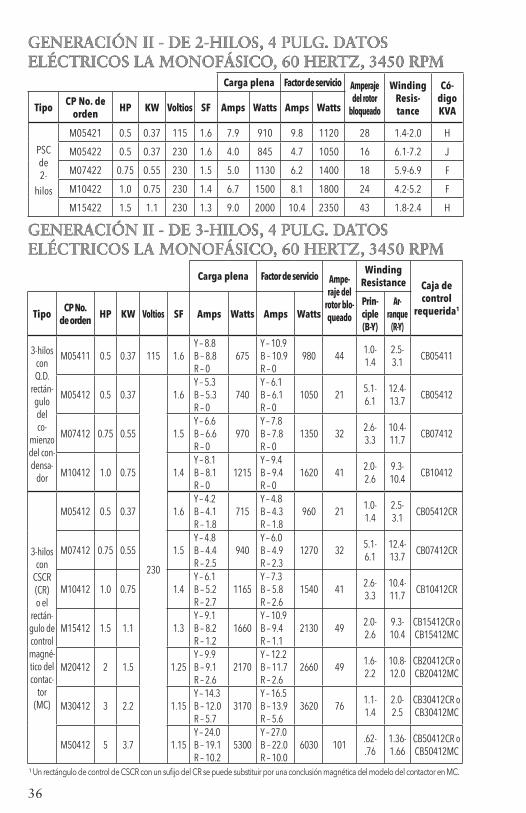
CB50412MC¹ A CSCR control box with a CR suffix can be replaced by a Magnetic Contactor model ending in MC.
14
PRESSURE SWITCHOR OTHER CONTROL
PUMPSAVER
111 / 233
L1IN
L1OUT
L2IN OUT
L2
FUSED DISCONNECTOR CIRCUIT BREAKER
GND L1 L2
PRESSURE SWITCHOR OTHER CONTROL
L1
L1
L1L1
L2
L2
L2L2
GND
GNDGND
PRESSURE SWITCH MAY BE INSTALLEDAHEAD OF THE PUMPSAVER WHENRAPID CYCLE PROTECTION IS NOT REQUIRED
GND
TO MOTOR OR CONTROL BOX
GND L2 L1
FUSED DISCONNECTOR CIRCUIT BREAKER
L1
L2
CT
L1SW L2 YEL BLK RED
DELUXE CONTROL BOX
PUMPMOTOR
TO PUMP
PUMP
PRESSURE SWITCHOR
OTHER CONTROL
L1 CT1 CT2 L2 IN L2 OUT
PUMPSAVER 235PUMPSAVER 235 PUMPSAVER 111 / 233PUMPSAVER 111 / 233
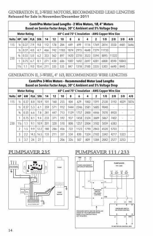
GENERATION II, 2-WIRE MOTORS, RECOMMENDED LEAD LENGTHSReleased for Sale in November/December 2011
GENERATION II, 3-WIRE, 4" 1Ø, RECOMMENDED WIRE LENGTHS
CentriPro Motor Lead Lengths - 2 Wire Motors, 1Ø, 4" Motors Based on Service Factor Amps, 30º C Ambient and 5% Voltage Drop
Motor Rating 60º C and 75º C Insulation - AWG Copper Wire Size
Volts HP kW FLA SFA 14 12 10 8 6 4 2 1/0 2/0 3/0 4/0
115 ½ 0.37 7.9 9.8 112 178 284 449 699 1114 1769 2814 3550 4481 5646
230
½ 0.37 4.0 4.7 466 742 1183 1874 2915 4648 7379 11733
¾ 0.55 5.0 6.2 353 562 897 1420 2210 3523 5594 8895 11222
1 0.75 6.7 8.1 271 430 686 1087 1692 2697 4281 6808 8590 10843
1½ 1.1 9.0 10.4 211 335 535 847 1318 2100 3335 5303 6690 8445
CentriPro 3-Wire Motors – Recommended Motor Lead Lengths Based on Service Factor Amps, 30º C Ambient and 5% Voltage Drop
Motor Rating 60º C and 75º C Insulation - AWG Copper Wire Size
Volts HP kW FLA SFA 14 12 10 8 6 4 2 1/0 2/0 3/0 4/0
115 ½ 0.37 8.8 10.9 101 160 255 404 629 1002 1591 2530 3192 4029 5076
230
½ 0.37 5.3 6.1 359 571 912 1444 2246 3581 5685 9040 - - -
¾ 0.55 6.6 7.8 281 447 713 1129 1757 2800 4446 7070 8920 - -
1 0.75 8.1 9.4 233 371 592 937 1458 2324 3689 5867 7402 - -
1½ 1.1 9.1 10.9 201 320 510 808 1257 2004 3182 5059 6383 - -
2 1.5 9.9 12.2 180 286 456 722 1123 1790 2843 4520 5703 - -
3 2.2 14.3 16.5 133 211 337 534 830 1324 2102 3342 4217 5323 -
5 3.7 24 27 - - 206 326 507 809 1284 2042 2577 3253 -

15
CENTRIPRO THREE PHASE, 4", MOTOR DATAEFFICIENCY, THRUST RATING, FUSE/CIRCUIT BREAKER, KVA CODES
Efficiency %Thrust
Rat-ing
KVA Code
Standard Fuse DE-TD Fuse Circuit
Breaker
Model # HP Volts F.L. S.F.
Meets NEC
based FLA
Max. Value based
SFA
Meets NEC
based FLA
Max. Value based
SFA
Meets NEC
based FLA
Max. Value based
SFAM05430 0.5
200
62 68
700 #
R 10 15 6 10 10 10
M07430 0.75 69 74 R 15 15 10 15 10 15
M10430 1 66 70 M 15 20 10 10 10 15
M15430 1.5 72 74 L 20 25 10 15 15 20
M20430 2 74 75900 #
K 25 30 15 20 20 25
M30430 3 77 77 K 35 40 20 25 30 35
M50430 5 76 761500 #
J 60 70 35 40 50 60
M75430 7.5 74 74 J 80 90 50 60 70 80
M05432 0.5
230
61 68
700 #
R 6 10 6 6 6 10
M07432 0.75 66 71 R 6 15 6 10 6 10
M10432 1 69 72 M 10 15 6 10 10 15
M15432 1.5 75 76 K 15 20 10 15 15 20
M20432 2 75 75900 #
K 15 25 15 15 20 20
M30432 3 77 77 J 25 35 15 20 25 30
M50432 5 76 761500 #
J 45 60 30 35 40 45
M75432 7.5 75 75 J 70 80 45 50 60 70
M05434 0.5
460
61 68
700 #
R 3 6 3 3 3 6
M07434 0.75 69 73 R 3 10 6 6 3 6
M10434 1 65 69 M 6 10 3 6 6 10
M15434 1.5 72 73 K 10 10 6 6 6 10
M20434 2 74 75900 #
L 15 15 6 10 10 10
M30434 3 76 77 J 15 20 10 10 15 15
M50434 5 77 77
1500 #
J 25 30 15 20 15 25
M75434 7.5 76 76 L 40 50 25 30 30 35
M100434 10 79 80 K 45 60 25 35 35 45
M15437 1.5
575
73 74 700 # J 6 10 3 6 6 10
M20437 2 78 78900 #
M 10 10 6 6 10 10
M30437 3 78 78 J 10 15 10 10 10 15
M50437 5 74 751500 #
M 20 25 15 15 20 20
M75437 7.5 77 77 J 25 35 20 20 25 30

16
THREE PHASE, 4" MOTOR DATA Electrical Data, 60 Hz, 3450 RPMTHREE PHASE 4" MOTOR DATA Electrical Data, 60 Hz, 3450 RPM
Full Load Service Factor Locked Line - Line Model # HP kW Volts SF Amps Watts Amps Watts Rotor Amps Resistance
M05430 0.5 0.37 1.6 2.9 600 3.4 870 22 4.1-5.2 M07430 0.75 0.55 1.5 3.8 812 4.5 1140 32 2.6-3.0 M10430 1 0.75 1.4 4.6 1150 5.5 1500 29 3.4-3.9 M15430 1.5 1.1
200 1.3 6.3 1560 7.2 1950 40 1.9-2.5
M20430 2 1.5 1.25 7.5 2015 8.8 2490 51 1.4-2.0 M30430 3 2.2 1.15 10.9 2890 12.0 3290 71 0.9-1.3 M50430 5 3.7 1.15 18.3 4850 20.2 5515 113 0.4-0.8 M75430 7.5 5.5 1.15 27.0 7600 30.0 8800 165 0.5-0.6 M05432 0.5 0.37 1.6 2.4 610 2.9 880 17.3 5.7-7.2 M07432 0.75 0.55 1.5 3.3 850 3.9 1185 27 3.3-4.3 M10432 1 0.75 1.4 4.0 1090 4.7 1450 26.1 4.1-5.1 M15432 1.5 1.1
230 1.3 5.2 1490 6.1 1930 32.4 2.8-3.4
M20432 2 1.5 1.25 6.5 1990 7.6 2450 44 1.8-2.4 M30432 3 2.2 1.15 9.2 2880 10.1 3280 58.9 1.3-1.7 M50432 5 3.7 1.15 15.7 4925 17.5 5650 93 .85-1.25 M75432 7.5 5.5 1.15 24 7480 26.4 8570 140 .55-.85 M05434 0.5 0.37 1.6 1.3 610 1.5 875 9 23.6-26.1 M07434 0.75 0.55 1.5 1.7 820 2.0 1140 14 14.4-16.2 M10434 1 0.75 1.4 2.2 1145 2.5 1505 13 17.8-18.8 M15434 1.5 1.1 1.3 2.8 1560 3.2 1980 16.3 12.3-13.1 M20434 2 1.5 460 1.25 3.3 2018 3.8 2470 23 8.0-8.67 M30434 3 2.2 1.15 4.8 2920 5.3 3320 30 5.9-6.5 M50434 5 3.7 1.15 7.6 4810 8.5 5530 48 3.58-4.00 M75434 7.5 5.5 1.15 12.2 7400 13.5 8560 87 1.9-2.3 M100434 10 7.5 1.15 15.6 9600 17.2 11000 110 1.8-2.2 M15437 1.5 1.1 1.3 2.0 1520 2.4 1950 11.5 19.8-20.6 M20437 2 1.5 1.25 2.7 1610 3.3 2400 21 9.4-9.7 M30437 3 2.2 575 1.15 3.7 2850 4.1 3240 21.1 9.4-9.7 M50437 5 3.7 1.15 7.0 5080 7.6 5750 55 3.6-4.2 M75437 7.5 5.5 1.15 9.1 7260 10.0 8310 55 3.6-4.2

17
Motor Lead Lengths – 3-Phase Motors – Based on Service Factor Amps, 30º C Ambient and 5% Voltage Drop
Motor Rating 60º C and 75º C Insulation - AWG Copper Wire Size
Volts HP kW FLA SFA 14 12 10 8 6 4 3 2 1 1/0 2/0 3/0 4/0 .5 .37 3.8 2.9 657 1045 1667 2641 4109 .75 .55 3.8 4.5 423 674 1074 1702 2648 1 .75 4.6 5.5 346 551 879 1392 2166 3454 4342
200 1.5 1.1 6.3 7.2 265 421 672 1064 1655 2638 3317
2 1.5 7.5 8.8 217 344 549 870 1354 2158 2714 3427 4317 5449 3 2.2 10.9 12.0 159 253 403 638 993 1583 1990 2513 3166 3996 5 3.7 18.3 20.2 94 150 239 379 590 940 1182 1493 1881 2374 2995 3781 4764 7.5 5.5 27.0 30.0 64 101 161 255 397 633 796 1005 1266 1598 2017 2546 3207 .5 .37 2.4 2.9 756 1202 1917 3037 4725 7532 9469 .75 .55 3.3 3.9 562 894 1426 2258 3513 5601 7041 8892 1 .75 4 4.7 466 742 1183 1874 2915 4648 5843 7379
230 1.5 1.1 5.2 6.1 359 571 912 1444 2246 3581 4502 5685 7162 9040
2 1.5 6.5 7.6 288 459 732 1159 1803 2874 3613 4563 5748 7256 9155 3 2.2 9.2 10.1 217 345 551 872 1357 2163 2719 3434 4326 5460 6889 8696 10956 5 3.7 15.7 17.5 318 503 783 1248 1569 1982 2496 3151 3976 5019 6323 7.5 5.5 24 26.4 334 519 827 1040 1314 1655 2089 2635 3327 4192 .5 .37 1.3 1.5 2922 4648 7414 .75 .55 1.7 2.0 2191 3486 5560 8806 1 .75 2.2 2.5 1753 2789 4448 7045 1.5 1.1 2.8 3.2 1370 2179 3475 5504 460 2 1.5 3.3 3.8 1153 1835 2926 4635 7212 3 2.2 4.8 5.3 827 1315 2098 3323 5171 5 3.7 7.6 8.5 516 820 1308 2072 3224 5140 7.5 5.5 12.2 13.5 325 516 824 1305 2030 3236 4068 5138 6472 10 7.5 1.5 1.1 2.0 2.4 2283 3631 5792 2 1.5 2.7 3.3 1660 2641 4212 6671 575 3 2.2 3.7 4.1 1336 2126 3390 5370 5 3.7 7.0 7.6 721 1147 1829 2897 4507 7.5 5.5 9.1 10.0 548 871 1390 2202 3426
THREE PHASE, 4" MOTOR WIRE CHARTTHREE PHASE 4" MOTOR WIRE CHART

18
Technical DataMOTOR INSULATION RESISTANCE READINGS
Normal Ohm/Megohm readings, ALL motors, between all leads and ground
Condition of Motor and Leads OHM Value Megohm Value New motor, without power cable 20,000,000 (or more) 20.0 Used motor, which can be reinstalled in well 10,000,000 (or more) 10.0
Motor in well – Readings are power cable plus motor New motor 2,000,000 (or more) 2.0 Motor in reasonably good condition 500,000 to 2,000,000 0.5 – 2.0 Motor which may be damaged or have damaged power cable 20,000 to 500,000 0.02 – 0.5 Do not pull motor for these reasons Motor definitely damaged or with damaged power cable 10,000 to 20,000 0.01 – 0.02 Pull motor and repair Failed motor or power cable Pull motor and repair Less than 10,000 0 – 0.01
To perform insulation resistance test, open breaker and disconnect all leads from QD control box or pressure switch.
Connect one ohmmeter lead to any motor lead and one to metal drop pipe or a good ground. R x 100K Scale
WARNING
Hazardous voltagecan shock, burn orcause death.
Generator OperationFAILURE TO USE A MANUAL OR AUTOMATIC TRANSFER SWITCH WHEN GENERATOR IS USED AS STANDBY OR BACKUP CAN CAUSE SHOCK, BURNS OR DEATH. FOLLOW THE GENERATOR MANUFACTURER’S INSTRUCTIONS CAREFULLY. TWO WIRE DATA IS ONLY FOR PSC TYPE MOTORS, SPLIT PHASE 2 WIRE SHOULD BE 50% LARGER THAN 3 WIRE GENERATOR RATING.
Generator Operation
Technical Data
CAUTION
Minimum Generator Rating Externally Regulated Internally Regulated Motor HP KW KVA KW KVA .5 2.5 3.1 1.8 2.2 .75 3.5 4.4 2.5 3.1 1 5 6.3 3.2 4 1.5 6 7.5 4 5 .5 2 2.5 1.5 1.9 .75 3 3.8 2 2.5 1 4 5 2.5 3.2 1.5 5 6.3 3 3.8 2 7.5 9.4 4 5 3 10 12.5 5 6.3 5 15 18.8 7.5 9.4 7.5 20 25 10 12.5 10 30 37.5 15 18.8
2 Wire1Ø
PSC Only
3 Wire1Ø or 3Ø

19
L1 L2
Disconnect Switch (2)
Pressure Switch (5)
Line
Load
Load
Line
NOTE: PumpSaver (6)
Pressure Switch (5)
Disconnect Switch (2)
Three WireControl Box (7)
L1 L2
Line
Load
Load
Line
1. Suministro de entrada de la caja de fusibles o del cortacircuitos
2. Interruptor de desconexión
3. Línea
4. Carga
5. Interruptor por caída de presión
6. NOTA: PumpSaver
7. Caja de control trifilar
8. Rojo
9. Amarillo
10. Negro
1. Courant d’entrée provenant de la boîte à fusibles ou du disjoncteur
2. Sectionneur
3. Ligne
4. Charge
5. Pressostat
6. Protection PumpSaver
7. Boîte de commande à trois fils
8. Rouge
9. Jaune
10. Noir
(3)
Two Wire – Direct Connected to Pressure Switch
Bifilar – conectado directamente al interruptor por caída de presión
Moteur à deux fils – connecté directement au pressostat
Figure (Figura) 3
Three Wire – Direct Connected to Pressure Switch
Trifilar – conectado directamente al interruptor por caída de presión
Moteur à trois fils – connecté directement au prossostat
Figure (Figura) 4
Incoming Supply from Fuse Box or Circuit Breaker (1)
NOTE: PumpSaver (6)
(4)
(3)
(4)
L1 L2
R Y Blk
Red
Yello
w
Black
(8)
(9) (10)
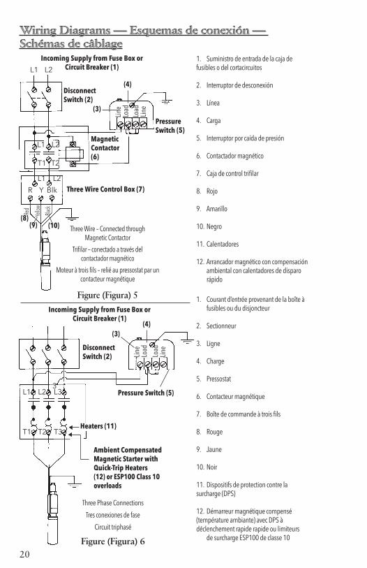
Wiring Diagrams — Esquemas de conexión — Schémas de câblageWiring Diagrams — Esquemas de conexión — Schémas de câblage
Incoming Supply from Fuse Box or Circuit Breaker (1)
20
Incoming Supply from Fuse Box or Circuit Breaker (1)L1 L2
Disconnect Switch (2)
Pressure Switch (5)
Line
Load
Load
Line
Magnetic Contactor (6)
Three Wire Control Box (7)
L1 L2
L1 L2
T1 T2
R Y Blk
Red
Yello
w
Black
Incoming Supply from Fuse Box or Circuit Breaker (1)
Disconnect Switch (2)
L1 L2 L3
T1 T2 T3Heaters (11)
Ambient CompensatedMagnetic Starter withQuick-Trip Heaters (12) or ESP100 Class 10 overloads
Pressure Switch (5)
Line
Load
Load
Line
Three Phase Connections
Tres conexiones de fase
Circuit triphasé
Figure (Figura) 6
1. Suministro de entrada de la caja de fusibles o del cortacircuitos
2. Interruptor de desconexión
3. Línea
4. Carga
5. Interruptor por caída de presión
6. Contactador magnético
7. Caja de control trifilar
8. Rojo
9. Amarillo
10. Negro
11. Calentadores
12. Arrancador magnético con compensación ambiental con calentadores de disparo rápido
1. Courant d’entrée provenant de la boîte à fusibles ou du disjoncteur
2. Sectionneur
3. Ligne
4. Charge
5. Pressostat
6. Contacteur magnétique
7. Boîte de commande à trois fils
8. Rouge
9. Jaune
10. Noir
11. Dispositifs de protection contre la surcharge (DPS)
12. Démarreur magnétique compensé (température ambiante) avec DPS à déclenchement rapide rapide ou limiteurs de surcharge ESP100 de classe 10
Three Wire – Connected through Magnetic Contactor
Trifilar – conectado a través del contactador magnético
Moteur à trois fils – relié au pressostat par un contacteur magnétique
Figure (Figura) 5
(8)(9) (10)
3
(3)
(4)
(3)(4)
Wiring Diagrams — Esquemas de conexión — Schémas de câblageWiring Diagrams — Esquemas de conexión — Schémas de câblage

21
DEFINITE PURPOSE THREE PHASE STARTERS WITH ADJUSTABLE OVERLOADS
CentriPro Order No.
Eaton ReferenceNumber
MaximumAmps
Supply Voltage
O.L. Relay
Overload Range
Maximum LRA
Typical HPRange
DP25D2 A27CGC25BA2P4
25 208-230
D 1.6-2.4
150 .5 - 5
DP25E2 A27CGC25BA004 E 2.4-4
DP25F2 A27CGC25BA006 F 4-6
DP25G2 A27CGC25BA010 G 6-10
DP25H2 A27CGC25BA016 H 10-16
DP25J2 A27CGC25BA024 J 16-24
DP25C4 A27CGC25CA1P6
25 460
C 1-1.6
125 .5 - 10
DP25D4 A27CGC25CA2P4 D 1.6-2.4
DP25E4 A27CGC25CA004 E 2.4-4
DP25F4 A27CGC25CA006 F 4-6
DP25G4 A27CGC25CA010 G 6-10
DP25H4 A27CGC25CA016 H 10-16
DP25J4 A27CGC25CA024 J 16-24
DP25E5 A27CGC25DA004
25 575
E 2.4-4
100 1.5 - 10DP25F5 A27CGC25DA006 F 4-6
DP25G5 A27CGC25DA010 G 6-10
DP25H5 A27CGC25DA016 H 10-16
DP30L2 A27CGE30BA010
30 208-230
L 6-10
180 1.5 - 7.5DP30M2 A27CGE30BA016 M 10-16
DP30N2 A27CGE30BA024 N 16-24
DP30P2 A27CGE30BA040 P 24-40
DP30L4 A27CGE30CA010
30 460
L 6-10
150 5 - 20DP30M4 A27CGE30CA016 M 10-16
DP30N4 A27CGE30CA024 N 16-24
DP30P4 A27CGE30CA040 P 24-40
DP30L5 A27CGE30DA010
30 575
L 6-10
120 5 - 15
DP30M5 A27CGE30DA016 M 10-16
DP30N5 A27CGE30DA024 N 16-24
DP30P5 A27CGE30DA040 P 24-40
DP30R5 A27CGE30DA057 R 40-57
DP40L2 A27CGE40BA010
40 208-230
L 6-10
240 1.5 - 10DP40M2 A27CGE40BA016 M 10-16
DP40N2 A27CGE40BA024 N 16-24
DP40P2 A27CGE40BA040 P 24-40
DP40L4 A27CGE40CA010
40 460
L 6-10
200 5 - 20DP40M4 A27CGE40CA016 M 10-16
DP40N4 A27CGE40CA024 N 16-24
DP40P4 A27CGE40CA040 P 24-40
DP40L5 A27CGE40DA010
40 575
L 6-10
160 5 - 20DP40M5 A27CGE40DA016 M 10-16
DP40N5 A27CGE40DA024 N 16-24
DP40P5 A27CGE40DA040 P 24-40

22
WARNING
Hazardous voltagecan shock, burn orcause death.
TroubleshootingDISCONNECT AND LOCKOUT ELECTRICAL POWER BE-FORE ATTEMPTING ANY SERVICE. FAILURE TO DO SO CAN CAUSE SHOCK, BURNS OR DEATH.
Symptom Probable Cause Recommended Action PUMP MOTOR NOT RUNNING
LITTLE OR NO LIQUID DELIVERED BY PUMP
1. Motor thermal protector tripped a. Incorrect control box b. Incorrect or faulty electrical connections c. Faulty thermal protector d. Low voltage e. Ambient temperature of control box/starter too high f. Pump bound by foreign matter g. Inadequate submergence
2. Open circuit breaker or blown fuse
3. Power source inadequate for load 4. Power cable insulation damage5. Faulty power cable splice
1. Allow motor to cool, thermal protector will automatically reset a – e. Have a qualified electrician inspect and repair, as required
f. Pull pump, clean, adjust set depth as required g. Confirm adequate unit submergence in pumpage
2. Have a qualified electrician inspect and repair, as required
3. Check supply or generator capacity4 – 5. Have a qualified electrician
inspect and repair, as required
1. Faulty or incorrectly installed check valve
2. Pump air bound
3. Lift too high for pump
4. Pump bound by foreign matter
5. Pump not fully submerged
6. Well contains excessive amounts of air or gases
7. Excessive pump wear
8. Incorrect motor rotation – three phase only.
1. Inspect check valve, repair as required
2. Successively start and stop pump until flow is delivered
3. Review unit performance, check with dealer
4. Pull pump, clean, adjust set depth as required
5. Check well recovery, lower pump if possible
6. If successive starts and stops does not remedy, well contains excessive air or gases
7. Pull pump and repair as required
8. Reverse any two motor electrical leads
Troubleshooting

23
Bomba sumergible de 4 pulg.INSTALACIÓN, OPERACIÓN Y MANUAL DEL MANTENIMIENTO
MANUAL DE INSTRUCCIÓNIM096

24
Información del propietario
Número de modelo de la bomba:
Número de serie de la bomba:
Número de modelo del motor:
Número de serie del motor:
Agente:
No. telefónico del agente:
Fecha de compra:
Fecha de instalación:
Voltios:
Amperios:
Información del propietario ÍndiceTEMA PÁGINA
Instrucciones de seguridad .........25-26Dispositivos de protección de la bomba ............................................. 28Lista de verificación de la instalación .......................... 28
1.0 Instalaciones típicas ................... 29
2.0 Tuberías y tanque ...................... 303.0 Tamaño y empalme de alambres y fuente de alimentación .............. 32
4.0 Cómo conectar los controles y el interruptor .............................. 33
5.0 Cómo arrancar la bomba .......... 36
6.0 Documentación y el manuel de instrucciones (IOM) .................... 36
Datos del motor monofásico CentriPro de 4"............................ 37Cuadros de tamaños de cable monofásico ................................. 37Diagrama del PumpSaver ................ 37Datos del motor trifásico ...........38-40Datos de resistencia y generador..... 41Diagramas de cableado ..............19-20Datos Técnicos ..............................41Arrancadores trifásicos ..................42Identificación y resolución de problemas .................................... 43
Garantía limitada ............................ 66
Índice

25
ADVERTENCIA
ADVERTENCIA
Todo el trabajo eléctrico debe ser realizado por un técnico calificado. Siempre siga el Código Eléctrico Nacional (NEC) o
el Código Eléctrico Canadiense, además de todos los códigos locales, estatales y provinciales. Las preguntas acerca del código deben ser dirigidas al inspector eléctrico local. Si se hace caso omiso a los códigos eléctricos y normas de se-guridad de OSHA, se pueden producir lesiones personales o daños al equipo. Si se hace caso omiso a las instrucciones de instalación del fabricante, se puede producir electrochoque, peligro de incendio, lesiones personales o incluso la muerte, daños al equipo, rendimiento insatisfactorio y podría anularse la garantía del fabricante.
Las unidades estándar no fueron diseñadas para su uso en piscinas, cuerpos abiertos de agua, líquidos peligrosos o donde
existan gases inflamables. El pozo debe contar con ventilación de acuerdo con los códigos locales. Vea los boletines de catálogos de bombas específicos o la placa de nombre de la bomba para todas las listas de agencias.
Desconecte y bloquee la corriente eléctrica antes de instalar o dar servicio a cualquier equipo eléctrico. Muchas bombas están equi-
padas con protección automática contra la sobrecarga térmica, la cual podría permitir que una bomba demasiado caliente rearranque inesperadamente.
Aviso importante: Lea las instrucciones de seguridad antes de proseguir con el cableado.
INSTRUCCIONES DE SEGURIDAD
PARA EVITAR LESIONES PERSONALES GRAVES O AÚN FATALES Y SERIOS DAÑOS MATERIALES, LEA Y SIGA TODAS LAS INSTRUCCIO-NES DE SEGURIDAD EN EL MANUAL Y EN LA BOMBA.ESTE MANUAL HA SIDO CREADO COMO UNA GUÍA PARA LA IN-STALACIÓN Y OPERACIÓN DE ESTA UNIDAD Y SE DEBE CONSER-VAR JUNTO A LA BOMBA.
Éste es un SÍMBOLO DE ALERTA DE SEGURIDAD. Cuando vea este símbolo en la bomba o en el manual, busque una de las siguientes palabras de señal y esté alerta a la probabilidad de lesiones personales o daños materiales.Advierte los peligros que CAUSARÁN graves lesiones personales, la muerte o daños materiales mayores.Advierte los peligros que PUEDEN causar graves lesiones personales, la muerte o daños materiales mayores.Advierte los peligros que PUEDEN causar lesiones personales o daños materiales.
AVISO: INDICA INSTRUCCIONES ESPECIALES QUE SON MUY IMPORTANTES Y QUE SE DEBEN SEGUIR DE RETROCESO DE DRENAJE; ESTOS SISTEMAS DEBEN UTILIZAR OTROS MEDIOS FRANKLIN ELECTRIC O EN UN MANUAL DEL CÓDIGO N.E.C. (CÓDIGO ELÉCTRICO NACIONAL DE LOS ESTADOS UNIDOS).EXAMINE BIEN TODAS LAS INSTRUCCIONES Y ADVERTENCIAS ANTES DE REALIZAR CUALQUIER TRABAJO EN ESTA BOMBA.MANTENGA TODAS LAS CALCOMANÍAS DE SEGURIDAD.
PELIGRO
ADVERTENCIA
PRECAUCIÓN
ADVERTENCIA
26
ADVERTENCIA
ADVERTENCIA
ADVERTENCIA
ADVERTENCIA
ADVERTENCIA
ADVERTENCIA
ADVERTENCIA
PELIGRO
ADVERTENCIA
PRECAUCIÓN
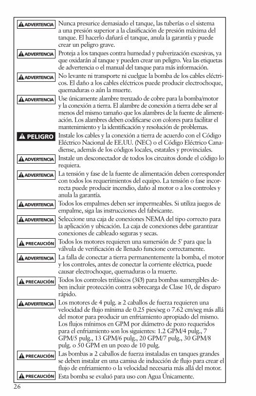
Nunca presurice demasiado el tanque, las tuberías o el sistema a una presión superior a la clasificación de presión máxima del tanque. El hacerlo dañará el tanque, anula la garantía y puede crear un peligro grave.Proteja a los tanques contra humedad y pulverización excesivas, ya que oxidarán al tanque y pueden crear un peligro. Vea las etiquetas de advertencia o el manual del tanque para más información. No levante ni transporte ni cuelgue la bomba de los cables eléctri-cos. El daño a los cables eléctricos puede producir electrochoque, quemaduras o aún la muerte.Use únicamente alambre trenzado de cobre para la bomba/motor y la conexión a tierra. El alambre de conexión a tierra debe ser al menos del mismo tamaño que los alambres de la fuente de aliment-ación. Los alambres deben codificarse con colores para facilitar el mantenimiento y la identificación y resolución de problemas.Instale los cables y la conexión a tierra de acuerdo con el Código Eléctrico Nacional de EE.UU. (NEC) o el Código Eléctrico Cana-diense, además de los códigos locales, estatales y provinciales.Instale un desconectador de todos los circuitos donde el código lo requiera.La tensión y fase de la fuente de alimentación deben corresponder con todos los requerimientos del equipo. La tensión o fase incor-recta puede producir incendio, daño al motor o a los controles y anula la garantía.Todos los empalmes deben ser impermeables. Si utiliza juegos de empalme, siga las instrucciones del fabricante.Seleccione una caja de conexiones NEMA del tipo correcto para la aplicación y ubicación. La caja de conexiones debe garantizar conexiones de cableado seguras y secas.Todos los motores requieren una sumersión de 5' para que la válvula de verificación de llenado funcione correctamente.La falla de conectar a tierra permanentemente la bomba, el motor y los controles, antes de conectar la corriente eléctrica, puede causar electrochoque, quemaduras o la muerte.Todos los controles trifásicos (3Ø) para bombas sumergibles de-ben incluir protección contra sobrecarga de Clase 10, de disparo rápido.Los motores de 4 pulg. ≥ 2 caballos de fuerza requieren una velocidad de flujo mínima de 0.25 pies/seg o 7.62 cm/seg más allá del motor para producir un enfriamiento apropiado del mismo. Los flujos mínimos en GPM por diámetro de pozo requeridos para el enfriamiento son los siguientes: 1.2 GPM/4 pulg., 7 GPM/5 pulg., 13 GPM/6 pulg., 20 GPM/7 pulg., 30 GPM/8 pulg. o 50 GPM en un pozo de 10 pulg. Las bombas ≥ 2 caballos de fuerza instaladas en tanques grandes se deben instalar en una camisa de inducción de flujo para crear el flujo de enfriamiento o la velocidad necesaria más allá del motor.Esta bomba se evaluó para uso con Agua Únicamente.
PRECAUCIÓN
PRECAUCIÓN
PRECAUCIÓN
ADVERTENCIA
ADVERTENCIA
27
LISTA DE VERIFICACIÓN DE LA INSTALACIÓN• Anote la información de la bomba y del motor y otros datos solicitados en la
portada de este manual.• Inspeccione todos los componentes para detectar daños de envío; notifique los
daños de inmediato al distribuidor.• Verifique la correspondencia de los caballos de fuerza del motor y de la bomba.• Haga corresponder la tensión y fase de la fuente de alimentación con las especifi-
caciones de control y del motor.• Seleccione un lugar sombreado y seco en el cual montar los controles.• Las conexiones de todos los empalmes sumergidos y subterráneos deben ser
impermeables.• Sujete la bomba en la cabeza de descarga cuando instale tubo roscado o un
accesorio adaptador, ya que la mayoría de las bombas tienen roscas de mano izquierda que se aflojarán si sujeta la bomba de cualquier otra parte.
• Revise todas las conexiones de plomería para verificar que estén ajustadas y sella-das con cinta de Teflon.
• Verifique que la clasificación de presión del tubo sea más alta que la presión de paro de la bomba.
• Instale una válvula de alivio de presión en todo sistema capaz de crear más de 75 PSI.
• Sitúe el interruptor por caída de presión a menos de 4 pies del tanque de presión para evitar el chasquido del interruptor.
• Ajuste la precarga del tanque 2 PSI por debajo de la presión de conexión del sistema, por ejemplo 28 en un sistema de 30/50.
• Instale la bomba 10 pies más arriba del fondo del pozo para mantenerla lejos de los sedimentos y residuos.
• Verifique que el suministro eléctrico principal esté desconectado y APAGADO antes de cablear los componentes.
• El cableado debe ser realizado por técnicos calificados únicamente.• El cableado y la puesta a tierra deben cumplir con los códigos nacionales y locales.• Restrinja el flujo con una válvula de bola o de globo, 1/3 abierta, antes de arrancar
la bomba por primera vez.• Abra un grifo o una válvula de descarga durante la puesta en marcha para evitar
que entre agua sucia al tanque.• ENCIENDA el cortacircuitos principal o el desconectador.• Active/desactive varias veces para verificar el funcionamiento correcto del inter-
ruptor.• Verifique los amperios y anote los datos en la portada de este manual.• Entregue el manual al propietario en el sitio de la obra.
PROTECCIÓN DE LA BOMBARecomendamos el uso del PumpSaver de SymCom para proteger al sistema contra bajo nivel de agua, ciclaje rápido, voltaje alto/bajo, funcionamiento de la bomba sin succión/restricción de flujo y sobretensión.

28
INSTALACIÓN DEL TANQUE CAPTIVE AIRAVISO: LOS CAMBIOS DE PRESIÓN DE PRECARGA DEL TANQUE DEBEN HACERSE CON LA VÁLVULA NEUMÁTICA EN EL EXTREMO SUPERIOR DEL TANQUE.
Figura 1
Figura 2
Fuente de alimentación protegidaInterruptor de desconexión
Caja de control Indicador de presión A la cañería de
la casa
Válvula de cierre
UniónDerivación de drenaje
Válvula de alivio de presión
Control de escape de aireInterruptor por caída de presión
Válvula de retención de línea con desahogo
UniónAdaptador sin cavidad
Accesorio de drenaje y en YPosición aproximada del accesorio de drenaje Distancia del accesorio de Capacidad del tanque drenaje y en “Y” por debajo de la válvula de retención de línea 159 L (42 galones) 7 pies (2.1m) 310 L (82 galones) 10 pies (3m) 454 L (120 galones) 15 pies (4.6m) 833 L (220 galones) 15 pies (4.6m) 1192 L (315 galones) 20 pies (6.1m) 1981 L (525 galones) 20 pies (6.1m)
INSTALACIÓN DE TANQUE GALVANIZADO
Fuente de alimentación protegida A la cañería de la casaInterruptor de desconexión
Válvula de cierre
Unión
Válvula de alivio de presión
Derivación de drenaje
T del tanqueNivel de helada Válvula de retención ②
Válvula de retención ①
Adaptador sin fosa ①
Interruptor por caída de presión
① En instalaciones con un adaptador sin fosa, la válvula de retención superior debe situarse debajo del área sin fosa y no en el tanque, ya que la línea de descarga se debe presurizar de regreso al área sin fosa.② En instalaciones con sellos de pozo o fosas de pozo, está permitido situar la válvula de retención superior cerca del tanque.
1.0 INSTALACIONES TÍPICAS 1.0 INSTALACIONES TÍPICAS

29
2.0 TUBERÍAAviso: La mayoría de las bombas sumergibles de 4 pulg. tienen roscas de mano izquierda en la cabeza de descarga; sujete la bomba sólo en la “cabeza de descarga” con una llave cuando instale accesorios o tubo roscado.
2.1 GeneralidadesLa tubería de descarga de la bomba debe dimensio-narse para producir un funcionamiento eficiente de la bomba. Utilice las
Tablas de pérdida por fricción para calcular la carga dinámica total em-pleando tubos de tamaños diferentes. Como regla práctica, utilice 1 pulg. para hasta 10 gpm, 1¼ pulg. para hasta 30 gpm, 1½ pulg. para hasta 45 gpm y 2 pulg. para hasta 80 gpm. En el caso de secciones largas de tubería es mejor aumentar el tamaño de la tubería.Algunas bombas son capaces de producir presiones de descarga muy altas; por lo tanto, seleccione el tubo que corresponda. Consulte con su proveedor de tubería para determinar el mejor tipo para cada instalación.
2.2 Tanque de presión, interruptor por caída de presión y válvula de alivio de presión
Elija una ubicación seca en la que la temperatura am-biente sea siempre superior
a 34º F (1º C) para instalar el tanque, el interruptor de presión y la válvula de alivio de presión. Se debe ubicar el tanque en un área en la que una pér-dida no causaría daños a la propiedad.El interruptor por caída de presión debe estar situado en la doble T del tanque y nunca a más de 4 pies del tanque. Si el interruptor se sitúa a
más de 4 pies del tanque, emitirá un chasquido. No instale válvulas, filtros o conexiones de alta absorción entre el interruptor y el/los tanque(s), ya que puede provocar el fallo del interrup-tor. Como ejemplo, una válvula de verificación de resorte de 1¼" tiene una pérdida de fricción equivalente a 12' de caño, colocar la válvula entre el interruptor de presión y el tanque de presión equivale a alejar al interruptor de presión 12' del tanque. Esto provocará un fallo en el interruptor.En instalaciones de varios tanques, el interruptor debe situarse lo más cerca posible del centro del tanque. Las instalaciones de varios tanques deben tener un tubo de distribución cuyo tamaño sea al menos 1½ veces el tamaño del tubo de suministro de la bomba. Esto reducirá la carga por fricción en el tubo de distribución y disminuirá la posibilidad de chasquido del interruptor.Se requieren válvulas de alivio de presión en cualquier sistema que sea capaz de producir 100 lbs./pulg. cuadrada o 230 pies de carga dinámica total. Si ésta es una área donde una purga o fuga de agua podría dañar la propiedad, conecte una línea de drenaje a la válvula de alivio de presión. Tiéndala a un drenaje adecuado o a un área donde el agua no dañará la propiedad.
2.3 Cómo ajustar la precarga del tanqueAsegúrese de que no haya nada de agua en el tanque. Utilice un indica-dor de presión de alta calidad para medir la presión de precarga del tanque. La presión debe ser 2 lbs./pulg. cuadrada menos que la presión de conexión de la bomba. Como ejemplo, un sistema de 30-50 lbs./pulg. cuadrada utilizaría una precarga del tanque de 28 lbs./pulg. cuadrada.
2.0 TUBERÍA
PRECAUCI N
Niveles de presi npeligrosos pueden causarlesiones personales oda os materiales.
No instale el tanque dondeesté sujeto a pulverizaciónde sistemas de irrigación.La exposición a dichapulverización podríacausar la corrosión deltanque y, a la larga, unaexplosión que puedecausar daños a la propie-dad, lesiones personalesgraves o muerte.
PELIGRO

30
2.4 Tubería de descarga y válvula de retenciónNota: La mayoría de las cabezas de descarga se atornillan en la carcasa con roscas de mano izquierda. Sólo sujete la bomba en la cabeza de des-carga cuando instale los accesorios. Si no se sujeta la cabeza de descarga, ésta se aflojará y se dañará la bomba al ponerla en marcha.Si la tubería necesita un adaptador, recomendamos enfáticamente utilizar acero inoxidable. Los accesorios o tuberías galvanizadas nunca deben conectarse directamente a una cabeza de descarga de acero inoxidable ya que podría producirse corrosión galvánica. Se puede utilizar cual-quier material para esta conexión en el caso de bombas de plástico o de latón. Los conectores tipo arpón siempre deben sujetarse con doble abrazadera.El cabezal de descarga de la bomba tiene un ojal para sujetar un cable de seguridad. Se recomienda el uso de un cable de seguridad al usar tuberías de poliuretano, ya que la tubería se estira cuando está bajo presión y llena de agua.
2.5 Cómo instalar la bomba en el pozoSi está utilizando un mecanismo antitorsión, instálelo de acuerdo con las instrucciones de instalación del fabricante. Solicite información al proveedor sobre mecanismos antitor-sión e instrucciones de instalación.Conecte la tubería de descarga a la cabeza de descarga o al adaptador que instaló previamente. Los conec-tores tipo arpón siempre deben sujetarse con doble abrazadera. Instale la bomba en el interior del pozo utilizando un adaptador sin fosa o dispositivo similar en el cabezal del pozo. Consulte con el fabricante
del accesorio o con el proveedor del adaptador con respecto a instruc-ciones específicas de instalación.Utilice cinta aislante impermeable para sujetar los alambres al tubo de bajada a intervalos de 10 pies. Asegúrese de que la cinta no se des-prenda ya que bloqueará la succión de la bomba si cae dentro del pozo. Los proveedores de bombas también venden conectores de alambre estilo presilla para sujetar el alambre al tubo de bajada.
2.6 Tubería especial para sistemas de tanques galvanizadosCuando utilice un tanque galvani-zado, debe instalar un accesorio de drenaje e “Y” AV11 en el pozo y una válvula de retención con vál-vula de desahogo en el tanque. Esto introducirá aire al tanque con cada arranque de la bomba y evitará el estancamiento del agua en el tanque. Utilice un escape de aire AA4 en el tanque para permitir el escape del ex-ceso de aire. La distancia entre AV11 y la válvula de desahogo determina la cantidad de aire que entra en cada ciclo. Consulte la tabla con respecto a los valores recomendados. Consulte la Fig. 2 en la Sección 1.0.En el caso de pozos de gas, deben utilizarse tanques galvanizados con escapes de aire AA4 para ventear el exceso de aire y evitar la “salida de agua por chorros” en las llaves. El metano y otros gases explosivos o peligrosos requieren un tratamiento especial del agua para extraerlos en forma segura. Consulte con un espe-cialista de tratamiento de agua para considerar estos asuntos.En las instalaciones con pozo de alimentación superior se deben usar camisas de flujo en la bomba.
31
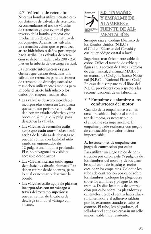
2.7 Válvulas de retenciónNuestras bombas utilizan cuatro esti-los distintos de válvulas de retención. Recomendamos el uso de válvulas de retención ya que evitan el giro inverso de la bomba y motor que producirá un desgaste prematuro de los cojinetes. Además, las válvulas de retención evitan que se produzca ariete hidráulico o daños por empuje hacia arriba. Las válvulas de reten-ción se deben instalar cada 200 - 250 pies en la tubería de descarga vertical.La siguiente información es para clientes que desean desactivar una válvula de retención para un sistema de retroceso de drenaje; estos siste-mas deben utilizar otros medios para impedir el ariete hidráulico o los daños por empuje hacia arriba:• Las válvulas de acero inoxidable
incorporadas tienen un área plana que se puede perforar con facili-dad con un taladro eléctrico y una broca de ¼ pulg. o 3⁄8 pulg. para desactivar la válvula.
• Las válvulas de retención estilo aguja que están atornilladas desde arriba de la cabeza de descarga se pueden retirar con facilidad utili-zando un entuercador de 12 pulg. o una boquilla profunda. El cubo hexagonal es visible y accesible desde arriba.
• Las válvulas internas estilo aguja de plástico de diseño Flomatic™ se deben retirar desde adentro, para lo cual es necesario desarmar la bomba.
• Las válvulas estilo aguja de plástico incorporadas con un vástago a través del extremo superior se pueden retirar de la cabeza de descarga tirando el vástago con alicates.
3.0 TAMAÑO Y EMPALME DE ALAMBRES y FUENTE DE ALI-MENTACIÓN
Siempre siga el Código Eléctrico de los Estados Unidos (N.E.C.) el Código Eléctrico del Canadá y cualquier código estatal o local.Sugerimos usar únicamente cable de cobre. Utilice el tamaño de cable que figura en la sección de Datos Técnicos de este manual, el manual MAID, o un manual de Código Eléctrico Nacio-nal (N.E.C. – National Electric Code). En caso de discrepancias, el libro del N.E.C. prevalecerá con respecto a las recomendaciones de un fabricante.
3.1 Empalme de alambre a los conductores del motorCuando deba empalmarse o conec-tarse un cable de bajada al conduc-tor del motor, es necesario que el empalme sea impermeable. El empalme puede realizarse con juegos de contracción por calor o cinta impermeable.
A. Instrucciones de empalme con juego de contracción por calorPara utilizar un juego típico de con-tracción por calor: pele ½ pulgada de los alambres del motor y de los alam-bres del cable de bajada; es mejor escalonar los empalmes. Coloque los tubos de contracción por calor sobre los alambres. Coloque los plegadores sobre los alambres y pliegue los ex-tremos. Deslice los tubos de contrac-ción por calor sobre los plegadores y caliéntelos desde el centro hacia afue-ra. El sellador y el adhesivo saldrán por los extremos cuando el tubo se contrae. El tubo, los plegadores, el sellador y el adhesivo crearán un sello impermeable muy resistente.
3.0 TAMAÑO Y EMPALME DE ALAMBRES y FUENTE DE ALI-MENTACIÓN
PELIGRO
La tensión peligrosapuede causar choques,quemaduras o la muerte.

32
B. Instrucciones de empalme con cintaA) Pele el aislamiento del conductor individual sólo lo necesario para dejar espacio para un conector tipo estaca. Se prefieren los conectores tubulares tipo estaca. Si el D.E. del conector no es tan grande como el aislamiento del cable, auméntelo con cinta aislante de caucho.B) Encinte las juntas individuales con cinta aislante de caucho, empleando dos capas; la primera extendiéndose dos pulgadas más allá de cada extremo de aislamiento del conductor, la segunda capa extendiéndose dos pulgadas más allá de la primera capa. Envuelva en forma apretada, eliminando los espacios de aire lo más posible.C) Aplique cinta aislante Scotch #33 o equivalente sobre la cinta aislante de caucho, empleando dos capas como en el paso “B” y haciendo que cada capa se superponga al menos dos pulgadas al extremo de la capa anterior.
En el caso de un cable con tres conductores recubiertos con un solo revestimiento exterior, encinte los conductores individuales en la forma descrita, alternando las juntas.El espesor total de la cinta no debe ser inferior al espesor del aislamiento del conductor.
4.0 CÓMO CONECTAR LOS CONTROLES y EL INTERRUPTOR
4.1 Cómo montar la caja de control del motorLas cajas de control monofásicas trifi-lares cumplen con los requerimientos de U.L. para las cubiertas tipo 3R. Son adecuadas para montaje verti-cal en lugares interiores y exteriores. Funcionarán a temperaturas entre 14ºF (-10ºC) y 122ºF (50ºC). Selec-cione un lugar sombreado y seco para montar la caja. Asegure que haya sufi-ciente espacio para quitar la tapa.
4.2 Verifique la tensión y apague la fuente de alimentaciónAsegure que la tensión del motor y la tensión de la fuente de aliment-ación sean iguales.Coloque el cortacircuitos o interrup-tor de desconexión en la posición OFF (de apagado) para evitar arran-car la bomba accidentalmente antes de que esté listo.Las bobinas de arrancadores trifásicos son muy sensibles a la tensión; siem-pre verifique la tensión de suministro real con un voltímetro.La alta o baja tensión, de más de ±10%, dañará los motores y con-troles y eso no está cubierto por la garantía.
PELIGRO
La tensión peligrosapuede causar choques,quemaduras o la muerte.
4.0 CÓMO CONECTAR LOS CONTROLES y EL INTERRUPTOR

33
4.3 Cómo conectar los conductores del motor a la caja de control del motor, interruptor por caída de presión o arrancador
Precaución No energice la unidad ni haga funcionar la bomba hasta que haya completado todas las conex-iones eléctricas y de tuberías. Verifique que el desconector
o cortacircuitos esté APAGADO antes de conectar los conductores de la línea del interruptor por caída de presión a la fuente de alimentación. Siga todos los códigos locales y nacionales. Utilice un desconector cuando el código así lo requiera.A. Motor monofásico trifilarConecte los conductores del motor codificados con colores a los termina-les de la caja de control del motor - Y (amarillo), R (rojo) y B (negro) y el alambre verde o desnudo al tornillo verde de puesta a tierra. Conecte los alambres entre los termi-nales de carga en el interruptor por caída de presión y los terminales L1 y L2 de la caja de control. Conecte un alambre de puesta a tierra entre la tierra del interruptor y la tierra de la caja de control. Consulte la Figura 4 ó 5B. Motor monofásico bifilarConecte los conductores negros del motor a los terminales de carga en el interruptor por caída de presión y el alambre verde o desnudo de puesta a tierra al tornillo verde de puesta a tierra. El motor CentriPro de dos hilos no funcionará con un PumpTec de Franklin Electric. Use un PumpSaver. Consulte la Figura 3C. Motores trifásicosConecte los conductores del motor a T1, T2 y T3 en el arrancador trifásico. Conecte el alambre de puesta a tierra al tornillo de puesta a tierra en la caja
del arrancador. Siga las instrucciones del fabricante del arrancador para conectar el interruptor por caída de presión o consulte la Figura 6.
4.4 Conexión a la fuente de alimentación
Complete el cableado haciendo la conexión desde los terminales de línea del interruptor por caída de presión monofásico hasta el panel de cortacircuitos o el
desconector en caso que se utilice.Instalaciones trifásicas – haga las conexiones entre L1, L2, L3 y tierra en el arrancador al desconector y luego al panel de cortacircuitos.Deben verificarse las instalaciones trifásicas con respecto a la rotación del motor y al desbalance de fase. Para invertir la rotación del motor, cambie (invierta) dos conductores cualquiera. Consulte las instrucciones para identificar el desbalance trifásico en la Sección Técnica de este manual. Si no se revisa el desbalance de fase, se puede producir una falla prematura del motor o un disparo por sobrecar-ga falso. Si está utilizando un genera-dor, consulte los Datos Técnicos para generadores.
4.5 Protección contra las sobrecargas en unidades trifásicasSólo use la protección de Clase 10, de disparo rápido contra las sobrecargas en los motores sumergibles trifásicos. Vea los arrancadores definidos del propósito en este manual.Llame al grupo de Servicio al Cliente del fabricante de la bomba para pedir asistencia para la selección.
PELIGRO
La tensión peligrosapuede causar choques,quemaduras o la muerte.
PELIGRO
La tensión peligrosapuede causar choques,quemaduras o la muerte.
34
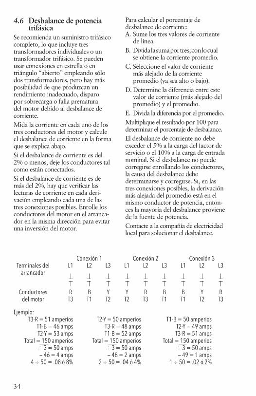
4.6 Desbalance de potencia trifásicaSe recomienda un suministro trifásico completo, lo que incluye tres transformadores individuales o un transformador trifásico. Se pueden usar conexiones en estrella o en triángulo “abierto” empleando sólo dos transformadores, pero hay más posibilidad de que produzcan un rendimiento inadecuado, disparo por sobrecarga o falla prematura del motor debido al desbalance de corriente. Mida la corriente en cada uno de los tres conductores del motor y calcule el desbalance de corriente en la forma que se explica abajo.Si el desbalance de corriente es del 2% o menos, deje los conductores tal como están conectados.Si el desbalance de corriente es de más del 2%, hay que verificar las lecturas de corriente en cada deri-vación empleando cada una de las tres conexiones posibles. Enrolle los conductores del motor en el arranca-dor en la misma dirección para evitar una inversión del motor.
Para calcular el porcentaje de desbalance de corriente:A. Sume los tres valores de corriente de línea.B. Divida la suma por tres, con lo cual se obtiene la corriente promedio.C. Seleccione el valor de corriente más alejado de la corriente promedio (ya sea alto o bajo).D. Determine la diferencia entre este valor de corriente (más alejado del promedio) y el promedio.E. Divida la diferencia por el promedio.Multiplique el resultado por 100 para determinar el porcentaje de desbalance.El desbalance de corriente no debe exceder el 5% a la carga del factor de servicio o el 10% a la carga de entrada nominal. Si el desbalance no puede corregirse enrollando los conductores, la causa del desbalance debe determinarse y corregirse. Si, en las tres conexiones posibles, la derivación más alejada del promedio está en el mismo conductor de potencia, enton-ces la mayoría del desbalance proviene de la fuente de potencia. Contacte a la compañía de electricidad local para solucionar el desbalance.
Conexión 1 Conexión 2 Conexión 3 Terminales del L1 L2 L3 L1 L2 L3 L1 L2 L3 arrancador
Conductores R B Y Y R B B Y R del motor T3 T1 T2 T2 T3 T1 T1 T2 T3
Ejemplo: T3-R = 51 amperios T2-Y = 50 amperios T1-B = 50 amperios T1-B = 46 amps T3-R = 48 amps T2-Y = 49 amps T2-Y = 53 amps T1-B = 52 amps T3-R = 51 amps Total = 150 amperios Total = 150 amperios Total = 150 amperios ÷ 3 = 50 amps ÷ 3 = 50 amps ÷ 3 = 50 amps — 46 = 4 amps — 48 = 2 amps — 49 = 1 amps 4 ÷ 50 = .08 ó 8% 2 ÷ 50 = .04 ó 4% 1 ÷ 50 = .02 ó 2%

35
5.0 CÓMO ARRANCAR LA BOMBA
5.1 Instale una válvula y haga funcionar la bomba para limpiar el aguaEn un pozo nuevo - Instale
una válvula esférica o de globo en la línea de descarga de la bomba y con la válvula 1⁄3 abierta, bombee el pozo hasta que el agua salga limpia. Abra la vál-vula lentamente para verificar el flujo y, cuando el agua salga limpia, apague la bomba.Retire la válvula esférica o de globo y conecte la descarga de la bomba a cañería de la casa, el tanque de presión y el interruptor. Encienda la bomba. Permita que la bomba funcione varios ciclos para que se enjuague y para verificar que la bomba y el interruptor funcionen correctamente. Aproveche este tiempo para fijarse si las conex-iones presentan pérdidas.CUIDADO: Si el pozo tiene un nivel estático alto, vea la próxima sección con información importante para la protección de la bomba.
5.2 Estrangulación de un pozo de alto nivel estático para evitar el empuje hacia arribaCualquier pozo con un
alto nivel estático de agua podría permitir que la bomba funcione fuera de la curva a la derecha o fuera del “intervalo recomendado” mostrado en la curva de la bomba. Recomenda-mos utilizar un restrictor de flujo “Dole” o estrangular con una válvula de bola para evitar el daño por em-puje hacia arriba a la bomba y al mo-tor. Debe restringirse el flujo máximo para que esté dentro del intervalo de funcionamiento recomendado de la bomba. Si utiliza una válvula de bola,
ajústela, quite la manija, encinte la manija al tubo y etiquete la válvula con una nota que diga “No abra esta válvula o podría dañarse la bomba”. La manera más fácil de “ajustar” el flujo es llenar un cubo de 5 galones y medir el tiempo que lleva producir 5 galones. Calcule el flujo en gpm de acuerdo con este valor. A medida que el nivel de agua disminuye en el pozo, se reducirá el flujo debido al aumento de la carga y la válvula no interferirá con el rendimiento.
6.0 DOCUMENTACIÓN y EL MANUAL DE INSTRUCCIONES (IOM)Entregue este manual de instruc-ciones y su tarjeta al propietario. ¡Una etiqueta con su nombre y número de teléfono en el tanque o en la caja de control es una buena herramienta de venta para los negocios futuros!Actualmente, proveemos una etiqueta adicional de bomba que usted puede fijar en el IOM, colocar en una caja de control de 3 hilos o ubicar cerca del tanque y del interruptor de presión para identificación futura de la bomba.
6.0 DOCUMENTACIÓN y EL MANUAL DE INSTRUCCIONES (IOM)
PRECAUCI N
Niveles de presi npeligrosos pueden causarlesiones personales oda os materiales.
5.0 CÓMO ARRANCAR LA BOMBA
PRECAUCI N
Niveles de presi npeligrosos pueden causarlesiones personales oda os materiales.
36
GENERACIÓN II - DE 2-HILOS, 4 PULG. DATOS ELÉCTRICOS LA MONOFÁSICO, 60 HERTZ, 3450 RPM
GENERACIÓN II - DE 3-HILOS, 4 PULG. DATOS ELÉCTRICOS LA MONOFÁSICO, 60 HERTZ, 3450 RPM
Carga plena Factor de servicio Amperaje del rotor
bloqueado
Winding Resis-tance
Có-digo KVATipo CP No. de
orden HP KW Voltios SF Amps Watts Amps Watts
PSC de 2-
hilos
M05421 0.5 0.37 115 1.6 7.9 910 9.8 1120 28 1.4-2.0 H
M05422 0.5 0.37 230 1.6 4.0 845 4.7 1050 16 6.1-7.2 J
M07422 0.75 0.55 230 1.5 5.0 1130 6.2 1400 18 5.9-6.9 F
M10422 1.0 0.75 230 1.4 6.7 1500 8.1 1800 24 4.2-5.2 F
M15422 1.5 1.1 230 1.3 9.0 2000 10.4 2350 43 1.8-2.4 H
Carga plena Factor de servicio Ampe-raje del
rotor blo-queado
Winding Resistance Caja de
control requerida1
Tipo CP No. de orden HP KW Voltios SF Amps Watts Amps Watts
Prin-ciple (B-Y)
Ar-ranque
(R-Y)
3-hilos con Q.D.
rectán-gulo del co-
mienzo del con-densa-
dor
M05411 0.5 0.37 115 1.6Y – 8.8B – 8.8 R – 0
675Y – 10.9B – 10.9R – 0
980 44 1.0-1.4
2.5-3.1 CB05411
M05412 0.5 0.37
230
1.6Y – 5.3 B – 5.3R – 0
740Y – 6.1B – 6.1 R – 0
1050 21 5.1-6.1
12.4-13.7 CB05412
M07412 0.75 0.55 1.5Y – 6.6B – 6.6 R – 0
970Y – 7.8B – 7.8R – 0
1350 32 2.6-3.3
10.4-11.7 CB07412
M10412 1.0 0.75 1.4Y – 8.1B – 8.1R – 0
1215Y – 9.4B – 9.4R – 0
1620 41 2.0-2.6
9.3-10.4 CB10412
3-hilos con
CSCR (CR) o el
rectán-gulo de control magné-tico del contac-
tor (MC)
M05412 0.5 0.37 1.6Y – 4.2B – 4.1R – 1.8
715Y – 4.8B – 4.3R – 1.8
960 21 1.0-1.4
2.5-3.1 CB05412CR
M07412 0.75 0.55 1.5Y – 4.8B – 4.4R – 2.5
940Y – 6.0B – 4.9R – 2.3
1270 32 5.1-6.1
12.4-13.7 CB07412CR
M10412 1.0 0.75 1.4Y – 6.1B – 5.2R – 2.7
1165Y – 7.3B – 5.8R – 2.6
1540 41 2.6-3.3
10.4-11.7 CB10412CR
M15412 1.5 1.1 1.3Y – 9.1B – 8.2R – 1.2
1660Y – 10.9B – 9.4R – 1.1
2130 49 2.0-2.6
9.3-10.4
CB15412CR o CB15412MC
M20412 2 1.5 1.25Y – 9.9B – 9.1R – 2.6
2170Y – 12.2B – 11.7R – 2.6
2660 49 1.6-2.2
10.8-12.0
CB20412CR o CB20412MC
M30412 3 2.2 1.15Y – 14.3B – 12.0R – 5.7
3170Y – 16.5B – 13.9R – 5.6
3620 76 1.1-1.4
2.0-2.5
CB30412CR o CB30412MC
M50412 5 3.7 1.15Y – 24.0B – 19.1R – 10.2
5300Y – 27.0B – 22.0R – 10.0
6030 101 .62-.76
1.36-1.66
CB50412CR o CB50412MC
¹ Un rectángulo de control de CSCR con un sufijo del CR se puede substituir por una conclusión magnética del modelo del contactor en MC.
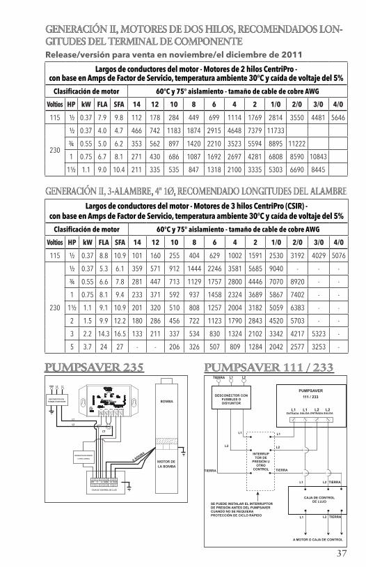
37
CAJA DE CONTROL DE LUJO
PUMPSAVER
111 / 233
L1ENTRADA
L1SALIDA
L2ENTRADASALIDA
L2
DESCONECTOR CON FUSIBLES O DISYUNTOR
TIERRA L1 L2
INTERRUPTOR DE
PRESIÓN U OTRO
CONTROL
L1
L1
L1L1
L2
L2
L2L2
TIERRA
TIERRATIERRA
SE PUEDE INSTALAR EL INTERRUPTOR DE PRESIÓN ANTES DEL PUMPSAVER CUANDO NO SE REQUIERA PROTECCIÓN DE CICLO RÁPIDO
TIERRA
A MOTOR O CAJA DE CONTROL
GND L2 L1
DESCONECTOR CON FUSIBLES O DISYUNTOR
L1
L2
CT
L1INT. L2 AMAR LK ROJO
CAJA DE CONTROL DE LUJO
MOTOR DE LA BOMBA
A BOMBA
BOMBA
INTERRUPTOR DE PRESIÓN
U OTRO CONTROL
L1 CT1 CT2 L2 IN L2 OUT
PUMPSAVER 235PUMPSAVER 235 PUMPSAVER 111 / 233PUMPSAVER 111 / 233
GENERACIÓN II, MOTORES DE DOS HILOS, RECOMENDADOS LON-GITUDES DEL TERMINAL DE COMPONENTERelease/versión para venta en noviembre/el diciembre de 2011
GENERACIÓN II, 3-ALAMBRE, 4" 1Ø, RECOMENDADO LONGITUDES DEL ALAMBRE
Largos de conductores del motor - Motores de 2 hilos CentriPro - con base en Amps de Factor de Servicio, temperatura ambiente 30°C y caída de voltaje del 5%
Clasificación de motor 60°C y 75° aislamiento - tamaño de cable de cobre AWG
Voltios HP kW FLA SFA 14 12 10 8 6 4 2 1/0 2/0 3/0 4/0
115 ½ 0.37 7.9 9.8 112 178 284 449 699 1114 1769 2814 3550 4481 5646
230
½ 0.37 4.0 4.7 466 742 1183 1874 2915 4648 7379 11733
¾ 0.55 5.0 6.2 353 562 897 1420 2210 3523 5594 8895 11222
1 0.75 6.7 8.1 271 430 686 1087 1692 2697 4281 6808 8590 10843
1½ 1.1 9.0 10.4 211 335 535 847 1318 2100 3335 5303 6690 8445
Largos de conductores del motor - Motores de 3 hilos CentriPro (CSIR) - con base en Amps de Factor de Servicio, temperatura ambiente 30°C y caída de voltaje del 5%
Clasificación de motor 60°C y 75° aislamiento - tamaño de cable de cobre AWG
Voltios HP kW FLA SFA 14 12 10 8 6 4 2 1/0 2/0 3/0 4/0
115 ½ 0.37 8.8 10.9 101 160 255 404 629 1002 1591 2530 3192 4029 5076
230
½ 0.37 5.3 6.1 359 571 912 1444 2246 3581 5685 9040 - - -
¾ 0.55 6.6 7.8 281 447 713 1129 1757 2800 4446 7070 8920 - -
1 0.75 8.1 9.4 233 371 592 937 1458 2324 3689 5867 7402 - -
1½ 1.1 9.1 10.9 201 320 510 808 1257 2004 3182 5059 6383 - -
2 1.5 9.9 12.2 180 286 456 722 1123 1790 2843 4520 5703 - -
3 2.2 14.3 16.5 133 211 337 534 830 1324 2102 3342 4217 5323 -
5 3.7 24 27 - - 206 326 507 809 1284 2042 2577 3253 -
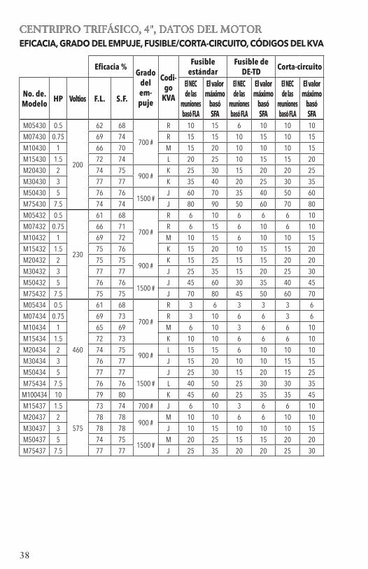
38
CENTRIPRO TRIFÁSICO, 4", DATOS DEL MOTOREFICACIA, GRADO DEL EMPUJE, FUSIBLE/CORTA-CIRCUITO, CÓDIGOS DEL KVA
Eficacia %Grado
del em-puje
Codi-go
KVA
Fusible estándar
Fusible de DE-TD Corta-circuito
No. de. Modelo HP Voltios F.L. S.F.
El NEC de las
reuniones basó FLA
El valor máximo
basó SFA
El NEC de las
reuniones basó FLA
El valor máximo
basó SFA
El NEC de las
reuniones basó FLA
El valor máximo
basó SFA
M05430 0.5
200
62 68
700 #
R 10 15 6 10 10 10
M07430 0.75 69 74 R 15 15 10 15 10 15
M10430 1 66 70 M 15 20 10 10 10 15
M15430 1.5 72 74 L 20 25 10 15 15 20
M20430 2 74 75900 #
K 25 30 15 20 20 25
M30430 3 77 77 K 35 40 20 25 30 35
M50430 5 76 761500 #
J 60 70 35 40 50 60
M75430 7.5 74 74 J 80 90 50 60 70 80
M05432 0.5
230
61 68
700 #
R 6 10 6 6 6 10
M07432 0.75 66 71 R 6 15 6 10 6 10
M10432 1 69 72 M 10 15 6 10 10 15
M15432 1.5 75 76 K 15 20 10 15 15 20
M20432 2 75 75900 #
K 15 25 15 15 20 20
M30432 3 77 77 J 25 35 15 20 25 30
M50432 5 76 761500 #
J 45 60 30 35 40 45
M75432 7.5 75 75 J 70 80 45 50 60 70
M05434 0.5
460
61 68
700 #
R 3 6 3 3 3 6
M07434 0.75 69 73 R 3 10 6 6 3 6
M10434 1 65 69 M 6 10 3 6 6 10
M15434 1.5 72 73 K 10 10 6 6 6 10
M20434 2 74 75900 #
L 15 15 6 10 10 10
M30434 3 76 77 J 15 20 10 10 15 15
M50434 5 77 77
1500 #
J 25 30 15 20 15 25
M75434 7.5 76 76 L 40 50 25 30 30 35
M100434 10 79 80 K 45 60 25 35 35 45
M15437 1.5
575
73 74 700 # J 6 10 3 6 6 10
M20437 2 78 78900 #
M 10 10 6 6 10 10
M30437 3 78 78 J 10 15 10 10 10 15
M50437 5 74 751500 #
M 20 25 15 15 20 20
M75437 7.5 77 77 J 25 35 20 20 25 30

39
DATOS DEL MOTOR DE 4" TRIFÁSICO DATOS ELÉCTRICOS, 60 HZ, 3450 RPM
Carga plena Factor de servicio Amperaje Línea – No. de
HP kW Voltios SF Amps Vatios Amps Vatios del Rotor Resistencia
Modelo bloqueado línea M05430 0.5 0.37 1.6 2.9 600 3.4 870 22 4.1 - 5.2 M07430 0.75 0.55 1.5 3.8 812 4.5 1140 32 2.6-3.0 M10430 1 0.75 1.4 4.6 1150 5.5 1500 29 3.4-3.9 M15430 1.5 1.1
200 1.3 6.3 1560 7.2 1950 40 1.9-2.5
M20430 2 1.5 1.25 7.5 2015 8.8 2490 51 1.4-2.0 M30430 3 2.2 1.15 10.9 2890 12.0 3290 71 0.9-1.3 M50430 5 3.7 1.15 18.3 4850 20.2 5515 113 0.4-0.8 M75430 7.5 5.5 1.15 27.0 7600 30.0 8800 165 0.5-0.6 M05432 0.5 0.37 1.6 2.4 610 2.9 880 17.3 5.7 - 7.2 M07432 0.75 0.55 1.5 3.3 850 3.9 1185 27 3.3 - 4.3 M10432 1 0.75 1.4 4.0 1090 4.7 1450 26.1 4.1-5.1 M15432 1.5 1.1
230 1.3 5.2 1490 6.1 1930 32.4 2.8-3.4
M20432 2 1.5 1.25 6.5 1990 7.6 2450 44 1.8-2.4 M30432 3 2.2 1.15 9.2 2880 10.1 3280 58.9 1.3-1.7 M50432 5 3.7 1.15 15.7 4925 17.5 5650 93 .85-1.25 M75432 7.5 5.5 1.15 24 7480 26.4 8570 140 .55-.85 M05434 0.5 0.37 1.6 1.3 610 1.5 875 9 23.6 - 26.1 M07434 0.75 0.55 1.5 1.7 820 2.0 1140 14 14.4 - 16.2 M10434 1 0.75 1.4 2.2 1145 2.5 1505 13 17.8 - 18.8 M15434 1.5 1.1
460 1.3 2.8 1560 3.2 1980 16.3 12.3 - 13.1
M20434 2 1.5 1.25 3.3 2018 3.8 2470 23 8.0 - 8.67 M30434 3 2.2 1.15 4.8 2920 5.3 3320 30 5.9-6.5 M50434 5 3.7 1.15 7.6 4810 8.5 5530 48 3.58-4.00 M75434 7.5 5.5 1.15 12.2 7400 13.5 8560 87 1.9-2.3 M100434 10 7.5 1.15 15.6 9600 17.2 11000 110 1.8-2.2 M15437 1.5 1.1 1.3 2.0 1520 2.4 1950 11.5 19.8-20.6 M20437 2 1.5 1.25 2.7 1610 3.3 2400 21 9.4-9.7 M30437 3 2.2 575 1.15 3.7 2850 4.1 3240 21.1 9.4-9.7 M50437 5 3.7 1.15 7.0 5080 7.6 5750 55 3.6-4.2 M75437 7.5 5.5 1.15 9.1 7260 10.0 8310 55 3.6-4.2
DATOS DEL MOTOR DE 4" TRIFÁSICO DATOS ELÉCTRICOS, 60 HZ, 3450 RPM

40
CUADRO DE CABLE DEL MOTOR DE 4” TRIFÁSICOCUADRO DE CABLE DEL MOTOR DE 4” TRIFÁSICO
Largos de conductores de motor – Motores trifásicos - Con base en amperes de factor de servicio, temperatura ambiente 30°C y caída de tensión del 5%
Clasificación de motor 60°C y 75°C aislamiento - tamaño de cable de cobre AWG
Voltios HP kW FLA SFA 14 12 10 8 6 4 3 2 1 1/0 2/0 3/0 4/0 .5 .37 3.8 2.9 657 1045 1667 2641 4109 .75 .55 3.8 4.5 423 674 1074 1702 2648 1 .75 4.6 5.5 346 551 879 1392 2166 3454 4342
200 1.5 1.1 6.3 7.2 265 421 672 1064 1655 2638 3317
2 1.5 7.5 8.8 217 344 549 870 1354 2158 2714 3427 4317 5449 3 2.2 10.9 12.0 159 253 403 638 993 1583 1990 2513 3166 3996 5 3.7 18.3 20.2 94 150 239 379 590 940 1182 1493 1881 2374 2995 3781 4764 7.5 5.5 27.0 30.0 64 101 161 255 397 633 796 1005 1266 1598 2017 2546 3207 .5 .37 2.4 2.9 756 1202 1917 3037 4725 7532 9469 .75 .55 3.3 3.9 562 894 1426 2258 3513 5601 7041 8892 1 .75 4 4.7 466 742 1183 1874 2915 4648 5843 7379
230 1.5 1.1 5.2 6.1 359 571 912 1444 2246 3581 4502 5685 7162 9040
2 1.5 6.5 7.6 288 459 732 1159 1803 2874 3613 4563 5748 7256 9155 3 2.2 9.2 10.1 217 345 551 872 1357 2163 2719 3434 4326 5460 6889 8696 10956 5 3.7 15.7 17.5 318 503 783 1248 1569 1982 2496 3151 3976 5019 6323 7.5 5.5 24 26.4 334 519 827 1040 1314 1655 2089 2635 3327 4192 .5 .37 1.3 1.5 2922 4648 7414 .75 .55 1.7 2.0 2191 3486 5560 8806 1 .75 2.2 2.5 1753 2789 4448 7045 1.5 1.1 2.8 3.2 1370 2179 3475 5504 460 2 1.5 3.3 3.8 1153 1835 2926 4635 7212 3 2.2 4.8 5.3 827 1315 2098 3323 5171 5 3.7 7.6 8.5 516 820 1308 2072 3224 5140 7.5 5.5 12.2 13.5 325 516 824 1305 2030 3236 4068 5138 6472 10 7.5 1.5 1.1 2.0 2.4 2283 3631 5792 2 1.5 2.7 3.3 1660 2641 4212 6671 575 3 2.2 3.7 4.1 1336 2126 3390 5370 5 3.7 7.0 7.6 721 1147 1829 2897 4507 7.5 5.5 9.1 10.0 548 871 1390 2202 3426

41
Datos técnicosLECTURAS DE RESISTENCIA DEL AISLAMIENTO DEL MOTORLecturas normales en ohmios/megaohmios, TODOS los motores, entre todos los conductores y tierra
Condición del motor y los conductores Valor en OHMIOS Valor en Megaohmios Motor nuevo, sin cable de alimentación 20,000,000 (o más) 20.0 Motor usado, el cual puede reinstalarse en el pozo 10,000,000 (o más) 10.0
Motor en el pozo – lecturas del cable de alimentación más el motor Motor nuevo 2,000,000 (o más) 2.0 El motor está en relativamente buenas condiciones de 500,000 a 2,000,000 0.5 – 2.0 El motor podría estar dañado o con cable de alimentación dañado de 20,000 a 500,000 0.02 – 0.5 No retire el motor por estas razones Motor definitivamente dañado o con cable de alimentación dañado de 10,000 a 20,000 0.01 – 0.02 Retire y repare el motor Falla del motor o del cable de alimentación Retire y repare el motor menos de 10,000 0 – 0.01
Para realizar la prueba de resistencia de aislamiento, abra el cortacircuitos y desconecte todos los conductores de la caja
de control QD o del interruptor por caída de presión. Conecte un conductor del ohmímetro a cualquier conductor del motor y otro a un tubo de bajada de metal o a una tierra adecuada. Escala R x 100K
PELIGRO
La tensión peligrosapuede causar choques,quemaduras o la muerte.
Operación del generadorSI NO SE USA UN INTERRUPTOR DE TRANSFERENCIA MANUAL O AUTOMÁTICO CUANDO EL GENERADOR SE UTILIZA COMO UNIDAD DE RESERVA, SE PUEDE PRODUCIR ELECTROCHOQUE, QUEMADURAS O LA MUERTE. LOS DATOS DE DOS HILOS SON SOLO PARA MOTORES DEL TIPO PSC; 2 CABLES CON FASE DIVIDIDA DEBEN SER UN 50% MÁS GRANDES QUE LA CLASIFICACIÓN DE GENERADOR DE 3 HILOS.
Datos técnicos
Operación del generador
PRECAUCIÓN
Clasificación mínima del generador Regulado externamente Regulado internamente Motor HP KW KVA KW KVA 0,5 2,5 3,1 1,8 2,2 0,75 3,5 4,4 2,5 3,1 1 5 6,3 3,2 4 1,5 6 7,5 4 5 0,5 2 2,5 1,5 1,9 0,75 3 3,8 2 2,5 1 4 5 2,5 3,2 1,5 5 6,3 3 3,8 2 7,5 9,4 4 5 3 10 12,5 5 6,3 5 15 18,8 7,5 9,4 7,5 20 25 10 12,5 10 30 37,5 15 18,8
2 hilos1Ø
Solo PSC
3 hilos1Ø o 3

42
ARRANCADORES TRIFÁSICOS DEL PROPÓSITO DEFINIDO CON SOBRECARGAS AJUSTABLES
Orden de CentriPro no.
Número de refer-encia de Eaton
Máximo amperios
Voltaje de fuente
O.L. Relevo
Rango de la sobrecarga
Máximo LRA
Rango típico de HP
DP25D2 A27CGC25BA2P4
25 208-230
D 1.6-2.4
150 .5 - 5
DP25E2 A27CGC25BA004 E 2.4-4
DP25F2 A27CGC25BA006 F 4-6
DP25G2 A27CGC25BA010 G 6-10
DP25H2 A27CGC25BA016 H 10-16
DP25J2 A27CGC25BA024 J 16-24
DP25C4 A27CGC25CA1P6
25 460
C 1-1.6
125 .5 - 10
DP25D4 A27CGC25CA2P4 D 1.6-2.4
DP25E4 A27CGC25CA004 E 2.4-4
DP25F4 A27CGC25CA006 F 4-6
DP25G4 A27CGC25CA010 G 6-10
DP25H4 A27CGC25CA016 H 10-16
DP25J4 A27CGC25CA024 J 16-24
DP25E5 A27CGC25DA004
25 575
E 2.4-4
100 1.5 - 10DP25F5 A27CGC25DA006 F 4-6
DP25G5 A27CGC25DA010 G 6-10
DP25H5 A27CGC25DA016 H 10-16
DP30L2 A27CGE30BA010
30 208-230
L 6-10
180 1.5 - 7.5DP30M2 A27CGE30BA016 M 10-16
DP30N2 A27CGE30BA024 N 16-24
DP30P2 A27CGE30BA040 P 24-40
DP30L4 A27CGE30CA010
30 460
L 6-10
150 5 - 20DP30M4 A27CGE30CA016 M 10-16
DP30N4 A27CGE30CA024 N 16-24
DP30P4 A27CGE30CA040 P 24-40
DP30L5 A27CGE30DA010
30 575
L 6-10
120 5 - 15
DP30M5 A27CGE30DA016 M 10-16
DP30N5 A27CGE30DA024 N 16-24
DP30P5 A27CGE30DA040 P 24-40
DP30R5 A27CGE30DA057 R 40-57
DP40L2 A27CGE40BA010
40 208-230
L 6-10
240 1.5 - 10DP40M2 A27CGE40BA016 M 10-16
DP40N2 A27CGE40BA024 N 16-24
DP40P2 A27CGE40BA040 P 24-40
DP40L4 A27CGE40CA010
40 460
L 6-10
200 5 - 20DP40M4 A27CGE40CA016 M 10-16
DP40N4 A27CGE40CA024 N 16-24
DP40P4 A27CGE40CA040 P 24-40
DP40L5 A27CGE40DA010
40 575
L 6-10
160 5 - 20DP40M5 A27CGE40DA016 M 10-16
DP40N5 A27CGE40DA024 N 16-24
DP40P5 A27CGE40DA040 P 24-40

43
LA BOMBA ENTREGA POCO O NADA DE LÍQUIDO
1. Válvula de retención defectuosa o instalada incorrectamente
2. La bomba está atascada con aire
3. Elevación demasiado alta para la bomba
4. La bomba está atascada con materias extrañas
5. La bomba no está completamente sumergida
6. El pozo contiene demasiado aire o gases
7. Desgaste excesivo de la bomba
8. Rotación incorrecta del motor – uni-dades trifásicas únicamente.
1. Inspeccione la válvula de retención, repárela según sea necesario
2. Arranque y detenga la bomba sucesiva-mente hasta que haya flujo
3. Verifique el rendimiento de la unidad, consulte con agente
4. Retire la bomba, límpiela ajústela, fije la profundidad según sea requerido
5. Verifique la recuperación del pozo, baje la bomba si es posible
6. Si los arranques y paradas sucesivos no solucionan el problema, el pozo contiene demasiado aire o gases
7. Retire y repare la bomba, según sea necesario
8. Invierta dos conductores eléctricos cualesquiera del motor
Identificación y resolución de problemasDESCONECTE Y BLOQUEE LA CORRIENTE ELÉCTRICA ANTES INTENTAR DAR SERVICIO. DE LO CONTRARIO, SE PUEDE PRODUCIR ELECTROCHOQUE, QUEMADURAS O LA MUERTE.
Síntoma Causa probable Acción recomendada EL MOTOR DE LA BOMBA NO ESTÁ FUNCIONADO
1. Se disparó el protector térmico del motor a. Caja de control incorrecta b. Conexiones eléctricas incorrectas o defectuosas c. Protector térmico defectuoso d. Baja tensión e. La temperatura ambiente de la caja de control/arrancador es demasiado alta f. La bomba está atascada con materias extrañas g. Sumersión inadecuada
2. Cortacircuitos abierto o fusible quemado
3. La fuente de energía es inadecuada para la carga
4. Daño del aislamiento del cable de alimentación
5. Empalme defectuoso del cable de alimentación
1. Deje que el motor se enfríe, el protector térmico se reposicionará automáticamente a – e. Solicite que un electricista calificado inspeccione y repare, según sea requerido. f. Retire la bomba, límpiela, ajústela, fije la profundidad según sea requerido g. Confirme la sumersión adecuada de la unidad en el agua bombeada
2. Solicite que un electricista calificado inspeccione y repare, según sea requerido.
3. Verifique el suministro o la capacidad del generador
4 – 5. Solicite que un electricista califi-cado inspeccione y repare, según sea requerido.
Identificación y resolución de problemasPELIGRO
La tensión peligrosapuede causar choques,quemaduras o la muerte.

44
Pompes submersibles de 4 poDIRECTIVES D’INSTALLATION, D’UTILISATION ET D’ENTRETIEN
MANUEL D'UTILISATIONIM096

45
Informations pour le propriétaire
Nº de modèle de la pompe :
Nº de série de la pompe :
Nº de modèle du moteur :
Nº de série du moteur :
Détaillant :
Nº de téléphone du détaillant :
Date d’achat :
Date d’installation :
Tension (V) :
Intensité (A) :
Table des matières
SUJET PAGEConsignes de sécurité ....................46Protection de la pome ....................47Préparatifs d’installation ................481. Installations types ......................492. Tuyauterie et réservoir ...............503. Alimentation électrique, câblage et jonction ...................524. Connexion de la boîte de commande et du pressostat .......535. Mise en service de la pompe ......566. Documentation et manuel .........56Données sur les moteurs CentriPro de 1 Ø, de 4 po ..........57Calibres de fil des moteurs CentriPro de 1 Ø, à 2 ou 3 fils ...58PumpSaver .....................................58Schémas de câblage ...................19-20Données sur les moteurs CentriPro de 3 Ø, 60 Hz .......................59-60Longueur maximale des câbles de moteur de 3 Ø .......................61Données techniques .......................62Valeurs de résistance d'isolement du moteur ..................................62Utilisation d'une génératrice ..........63Démarreurs triphasés .....................64Diagnostic de anomalies ................65Garantie limitée .............................67
Table des matièresInformations pour le propriétaire

46
AVERTISSEMENT
AVERTISSEMENT
AVERTISSEMENT
L’installation électrique doit être entièrement effectuée par un technicien qualifié. Il faut toujours suivre les prescriptions
du code provincial ou national de l’électricité pertinent et les règlements lo-caux. Adresser toute question relative au code à un inspecteur en électricité. Le non-respect du code et des politiques de santé et de sécurité au travail peut entraîner des blessures et des dommages matériels. L’inobservation des directives d’installation fournies par le fabricant peut se traduire par un choc électrique, un incendie, des blessures ou la mort, ainsi que par des dom-mages matériels, des performances non satisfaisantes et l’annulation de la garantie du fabricant.
Les pompes standard ne sont pas conçues pour les piscines, l'eau libre, les liquides dangereux ni les gaz inflammables.
Aérer le puits selon les codes locaux. La plaque signalétique de la pompe et les feuillets du catalogue de pompes listent les organismes de normalisation.
Verrouiller la source de courant en position hors circuit avant l’installation ou l’entretien des dispositifs électriques.
Le protecteur thermique de certains moteurs coupe le courant lorsqu'il y a surcharge thermique et le rétablit automatiquement, redémarrant ainsi la pompe inopinément.
Pour le système et le réservoir, ne jamais utiliser une pression excédant la pression nominale maximale de ce dernier, afin
de ne pas l'endommager, annuler la garantie ni constituer un grave danger.
Avis important : lire les consignes de sécurité avant de procéder au câblage.
CONSIGNES DE SÉCURITÉ
AFIN DE PRÉVENIR LES BLESSURES GRAVES OU MORTELLES ET LES DOMMAGES MATÉRIELS IMPORTANTS, SUIVRE CHAQUE CONSIGNE DE SÉCURITÉ FIGURANT DANS LE MANUEL ET SUR LA POMPE.LE PRÉSENT MANUEL A POUR BUT DE FACILITER L’INSTALLATION ET L’UTILISATION DE LA POMPE ET DOIT ÊTRE CONSERVÉ PRÈS DE CELLE-CI.
Le symbole ci-contre est un SYMBOLE DE SÉCURITÉ employé pour signaler les mots-indicateurs dont on trouvera la description ci-dessous. Sa présence sert à attirer l’attention afin d’éviter les blessures et les dommages matériels.Prévient des risques qui VONT causer des blessures graves, la mort ou des dommages matériels importants.Prévient des risques qui PEUVENT causer des blessures graves, la mort ou des dommages matériels importants.Prévient des risques qui PEUVENT causer des blessures ou des dommages matériels.
AVIS : SERT À ÉNONCER LES DIRECTIVES SPÉCIALES DE GRANDE IMPORTANCE QUE L’ON DOIT SUIVRE.LIRE SOIGNEUSEMENT CHAQUE DIRECTIVE ET AVERTISSEMENT AVANT D’EFFECTUER TOUT TRAVAIL SUR LA POMPE.N’ENLEVER AUCUNE DÉCALCOMANIE DE SÉCURITÉ.
DANGER
AVERTISSEMENT
ATTENTION
AVERTISSEMENT
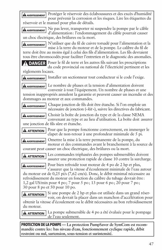
47
ATTENTION
AVERTISSEMENT
Protéger le réservoir des éclaboussures et des excès d'humidité pour prévenir la corrosion et les risques. Lire les étiquettes du
réservoir et le manuel pour plus de détails. Ne pas lever, transporter ni suspendre la pompe par le câble d’alimentation : l’endommagement du câble pourrait causer
un choc électrique, des brûlures ou la mort.N’utiliser que du fil de cuivre torsadé pour l’alimentation et la mise à la terre du moteur et de la pompe. Le calibre du fil de
terre doit être au moins égal à celui des fils d’alimentation. Les fils devraient tous être chromocodés pour faciliter l’entretien et le diagnostic des anomalies.
Poser le fil de terre et les autres fils suivant les prescriptions du code provincial ou national de l’électricité pertinent et les
règlements locaux.Installer un sectionneur tout conducteur si le code l’exige.
Le nombre de phases et la tension d’alimentation doivent convenir à tout l’équipement. Un nombre de phases et une
tension inappropriés annulent la garantie et peuvent causer un incendie et des dommages au moteur et aux commandes.
Chaque jonction de fils doit être étanche. Si l’on emploie un nécessaire de jonction (« kit »), suivre les directives du fabricant.Choisir la boîte de jonction du type et de la classe NEMA convenant au type et au lieu d’utilisation. La boîte doit assurer
une jonction de fils sûre et étanche.Pour que la pompe fonctionne correctement, en immerger le clapet de non-retour à une profondeur minimale de 5 pi.Omettre la mise à la terre permanente de la pompe, du moteur et des commandes avant le branchement à la source de
courant peut causer un choc électrique, des brûlures ou la mort.Les commandes triphasées des pompes submersibles doivent assurer une protection rapide de classe 10 contre la surcharge.Pour bien refroidir tout moteur de 4 po de 2 hp et plus, s’assurer que la vitesse d’écoulement minimale de l’eau autour
du moteur est de 0,25 pi/s (7,62 cm/s). Donc, le débit minimal nécessaire au refroidissement du moteur en fonction du calibre du tubage devrait être : 1,2 gal US/min pour 4 po ; 7 pour 5 po ; 13 pour 6 po ; 20 pour 7 po ; 30 pour 8 po et 50 pour 10 po.
Si une pompe de 2 hp et plus est utilisée dans un grand réser-voir, on devrait la placer dans un manchon d’accélération pour
obtenir la vitesse d’écoulement ou le débit nécessaires au bon refroidissement du moteur.
La pompe submersible de 4 po a été évaluée pour le pompage de l’eau seulement.
DANGER
ATTENTION
AVERTISSEMENT
AVERTISSEMENT
AVERTISSEMENT
AVERTISSEMENT
AVERTISSEMENT
AVERTISSEMENT
AVERTISSEMENT
ATTENTION
ATTENTION
AVERTISSEMENT
PROTECTION DE LA POMPE — La protection PumpSaver de SymCom est recom-mandée contre les : bas niveau d'eau, fonctionnement cyclique rapide, débit restreint ou nul, surtension, sous-tension et surintensité.
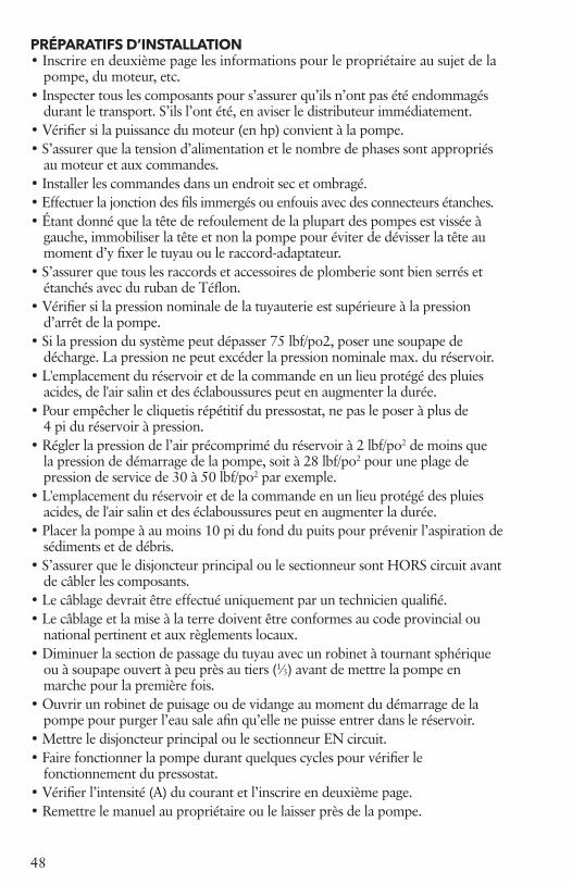
48
PRÉPARATIFS D’INSTALLATION• Inscrire en deuxième page les informations pour le propriétaire au sujet de la
pompe, du moteur, etc.• Inspecter tous les composants pour s’assurer qu’ils n’ont pas été endommagés
durant le transport. S’ils l’ont été, en aviser le distributeur immédiatement.• Vérifier si la puissance du moteur (en hp) convient à la pompe.• S’assurer que la tension d’alimentation et le nombre de phases sont appropriés
au moteur et aux commandes.• Installer les commandes dans un endroit sec et ombragé.• Effectuer la jonction des fils immergés ou enfouis avec des connecteurs étanches.• Étant donné que la tête de refoulement de la plupart des pompes est vissée à
gauche, immobiliser la tête et non la pompe pour éviter de dévisser la tête au moment d’y fixer le tuyau ou le raccord-adaptateur.
• S’assurer que tous les raccords et accessoires de plomberie sont bien serrés et étanchés avec du ruban de Téflon.
• Vérifier si la pression nominale de la tuyauterie est supérieure à la pression d’arrêt de la pompe.
• Si la pression du système peut dépasser 75 lbf/po2, poser une soupape de décharge. La pression ne peut excéder la pression nominale max. du réservoir.
• L'emplacement du réservoir et de la commande en un lieu protégé des pluies acides, de l'air salin et des éclaboussures peut en augmenter la durée.
• Pour empêcher le cliquetis répétitif du pressostat, ne pas le poser à plus de 4 pi du réservoir à pression.
• Régler la pression de l’air précomprimé du réservoir à 2 lbf/po2 de moins que la pression de démarrage de la pompe, soit à 28 lbf/po2 pour une plage de pression de service de 30 à 50 lbf/po2 par exemple.
• L'emplacement du réservoir et de la commande en un lieu protégé des pluies acides, de l'air salin et des éclaboussures peut en augmenter la durée.
• Placer la pompe à au moins 10 pi du fond du puits pour prévenir l’aspiration de sédiments et de débris.
• S’assurer que le disjoncteur principal ou le sectionneur sont HORS circuit avant de câbler les composants.
• Le câblage devrait être effectué uniquement par un technicien qualifié.• Le câblage et la mise à la terre doivent être conformes au code provincial ou
national pertinent et aux règlements locaux.• Diminuer la section de passage du tuyau avec un robinet à tournant sphérique
ou à soupape ouvert à peu près au tiers (1⁄3) avant de mettre la pompe en marche pour la première fois.
• Ouvrir un robinet de puisage ou de vidange au moment du démarrage de la pompe pour purger l’eau sale afin qu’elle ne puisse entrer dans le réservoir.
• Mettre le disjoncteur principal ou le sectionneur EN circuit.• Faire fonctionner la pompe durant quelques cycles pour vérifier le
fonctionnement du pressostat.• Vérifier l’intensité (A) du courant et l’inscrire en deuxième page.• Remettre le manuel au propriétaire ou le laisser près de la pompe.

49
1. INSTALLATIONS TYPESINSTALLATION À RÉSERVOIR À AIR CAPTIFAVIS : ON DOIT UTILISER LA VALVE À AIR COMPRIMÉ SITUÉE SUR LE DESSUS DU RÉSERVOIR POUR RÉGLER LA PRESSION D’AIR DE CELUI-CI.
Figure 1
Figure 2
Alimentation électrique protégéeSectionneur
Boîte de commande ManomètreVers la tuyauterie de la maison
Robinet de sectionnement
Raccord unionRobinet de vidange
Soupape de décharge
Commande d’échappement d’airPressostat (manostat)
Clapet de non-retour à reniflard
Raccordunion
Adaptateur de têtede puits
Raccord de vidangeen Y
Position approx. du raccord de vidange en Y Distance entre le raccord en Y
Volume total du réservoir et le clapet de non-retour
159 L (42 gal US) 2,1 m (7 pi) 310 L (82 gal US) 3 m (10 pi) 454 L (120 gal US) 4,6 m (15 pi) 833 L (220 gal US) 4,6 m (15 pi) 1 192 L (315 gal US) 6,1 m (20 pi) 1 987 L (525 gal US) 6,1 m (20 pi)
Alimentation électrique protégée Vers la tuyauterie de la maison
Sectionneur
Robinet de sectionnement
Raccord union
Soupape de décharge
Robinet de vidange
Té
Ligne de gel
INSTALLATION À RÉSERVOIR GALVANISÉ
Clapet de non-retour②Clapet de non-retour①
Adaptateur de tête de puits①
Pressostat (manostat)
① Dans les installations munies d’un adaptateur de tête de puits, le clapet de non-retour supérieur devrait être en amont de (avant) l’adaptateur et non près du réservoir, afin de maintenir l’adaptateur sous pression.
② Dans les installations à joint de puits ou à fosse d’aspiration, il est permis de poser le clapet de non-retour près du réservoir.
1. INSTALLATIONS TYPES

50
Les pressions dangereusespeuvent causer desblessures et desdommages matériels.
ATTENTION
2. Tuyauterie et réservoir
Avis : la tête de refoulement de la majorité des pompes submersibles de 4 po est vissée à gauche. Immobiliser la pompe uniquement par la « tête de refoulement » pour y fixer tout raccord ou tuyau fileté.
2.1. GénéralitésLe calibre de la tuyauterie de refoulement devrait être choisi pour permettre le rendement optimal de
la pompe. Calculer la hauteur manométrique totale en tenant compte des divers calibres de tuyau figurant dans les tables de perte de charge. En règle générale, on choisit le débit maximal selon le calibre : 10 gal US/min pour 1 po, 30 pour 1¼ po, 45 pour 1½ po et 80 pour 2 po. Si la tuyauterie est longue, il vaut mieux accroître le calibre.
Étant donné que certaines pompes produisent une pression de refoulement très élevée, choisir le tuyau en conséquence. Consulter un fournisseur de tuyaux pour déterminer le meilleur type de tuyau pour chaque installation.
2.2. Réservoir à pression, pressostat et soupape de déchargePour l'installation du réservoir, du pressostat et de la soupape de décharge,
choisir un endroit sec où la tempéra-ture dépassera toujours 1 °C (34 °F) et où aucune fuite ne pourra causer de dommages matériels.
Pour empêcher le cliquetis répétitif du pressostat, on devrait le poser près du té du réservoir, mais jamais à plus de 4 pi de celui-ci.
Ne poser entre le pressostat et le réservoir ni robinet, ni clapet de non-retour, ni filtre, ni raccord produisant une perte de charge (par frottement) élevée. Par exemple, la perte de charge d'un clapet à ressort de 1¼ po équivaut à une longueur de tuyau additionnelle de 12 pi. Donc, placer le clapet entre un réservoir et un pressostat reviendrait à les écarter de 12 pi de plus et à causer le clique-tis répétitif de ce dernier.
Dans les installations à réservoirs multiples, on devrait poser le presso-stat aussi près que possible du centre des réservoirs. Afin de réduire la hauteur équivalente de perte de charge (par frottement) dans le tuyau collecteur-répartiteur et d’empêcher le pressostat de cliqueter à répétition, on devrait employer un collecteur- répartiteur de calibre 1½ fois supé-rieur à celui du tuyau de refoulement de la pompe.
Une soupape de décharge est requise dans tout système ayant une pres-sion supérieure à 100 lbf/po2 ou une HMT supérieure à 230 pi. Si l'éjection de fluide par la soupape peut causer des dommages, en relier la sortie à un tuyau d'évacuation ap-proprié avec une conduite.
2. Tuyauterie et réservoir
Ne pas placer le réservoiren un lieu non protégédu jet d'un systèmed'irrigation, car il enrésulterait la corrosiondu réservoir et tôt outard l'explosion de celui-ci, pouvant causerdes dommagesmatériels, de gravesblessures, voire la mort.
DANGER

51
2.3. Réglage de la pression de l’air précomprimé du réservoir
S’assurer que le réservoir est vide. Utiliser un manomètre de haute qualité pour vérifier la pression de l’air précomprimé du réservoir. Celle-ci devrait être inférieure de 2 lbf/po2 à la pression de démarrage de la pompe. Par exemple, elle serait de 28 lbf/po2 dans un système dont la pression de service est de 30 à 50 lbf/po2.
2.4. Tuyau de refoulement et clapet de non-retour
Nota : la plupart des têtes de refoule-ment sont vissées à gauche. Pour fixer un raccord ou un tuyau sur la pompe, n'immobiliser celle-ci que par la tête de refoulement pour ne pas desserrer la pompe et risquer de l'abîmer au démarrage.
Si le tuyau de refoulement requiertun adaptateur, il est fortement recommandé d’en poser un en inox. Pour prévenir la corrosion galva-nique, on ne devrait jamais fixer de raccords, de tuyaux ni d’accessoires de tuyauterie galvanisés directement sur la tête de refoulement. À ce sujet, aucun matériau de fabrication n’est interdit pour les têtes de refoulement en plastique ou en laiton. Les rac-cords à barbillons devraient toujours être assujettis avec deux colliers de serrage.
La tête de refoulement possède un œil de fixation pour câble de sécurité. Le câble est recommandé quand on utilise un tuyau en polypropylène, qui s'allonge lorsqu'il est sous pres-sion ou plein d'eau.
2.5. Mise en place de la pompe
Si l’on emploie un dispositif antitorsion, le poser selon les directives du fabricant du dispositif. Pour plus de détails, consulter le vendeur du dispositif.
Raccorder le tuyau de refoulement à l’adaptateur ou à la tête de refoulement de la pompe. Les rac-cords à barbillons devraient toujours être assujettis avec deux colliers de serrage. Poser un adaptateur de tête de puits ou autre dispositif du même type pour y raccorder le tuyau de refoulement de la pompe. S’adresser au fabricant ou au vendeur de l’adaptateur ou du dispositif en question pour obtenir les directives d’installation pertinentes.
Avec du ruban isolant (chatterton) étanche, fixer les fils d’alimentation au tuyau de refoulement à tous les 10 pi. Les fournisseurs de pompes vendent des attaches encliquetables à cette fin.
2.6. Accessoires de tuyauterie spéciaux pour systèmes à réservoir galvanisé
Lorsque l’on utilise un réservoir galvanisé, on devrait poser un raccord de vidange en Y AV11 dans le puits et un clapet de non-retour à reniflard au réservoir. On permettra ainsi l’entrée d’air dans le réservoir pour empêcher le réservoir de trop s’emplir d’eau. Poser une commande d’échappement d’air AA4 sur le réservoir pour en laisser sortir l’excès d’air. La distance entre l'AV11 et le clapet de non-retour à reniflard détermine la quantité d’air admise à chaque démarrage. Voir la distance recommandée dans la figure 2.
52
Si le puits dégage du gaz, il est pré-férable de munir le réservoir en acier vitrifié ou galvanisé d’une commande d’échappement d’air AA4 pour évacuer le surplus d’air et en prévenir le « jaillissement » du robinet.
On doit soumettre l’eau contenant du méthane ou tout gaz explosif ou dan-gereux à un traitement spécial per-mettant d’éliminer le gaz en question sans danger. À cet effet, consulter un spécialiste du traitement de l’eau.
Quant aux puits alimentés par le haut, il faudrait poser un manchon d’accélération de l’écoulement de l’eau autour de la pompe.
2.7 Clapets de non-retourQuatre types de clapets de non- retour sont utilisés. Ces clapets sont recommandés pour empêcher le liquide de redescendre dans la pompe et de faire ainsi tourner le moteur et la pompe en sens inverse, ce qui en provoquerait l’usure prématurée des roulements et des coussinets. En outre, les clapets préviennent les dommages dus aux coups de bélier et aux poussées axiales. Un clapet de non-retour supplémentaire devrait être posé à tous les 200 pi sur le tron-çon vertical du tuyau de refoulement. Voir les textes 1 et 2 de la figure 1pour les autres positions recom-mandées.
Si l'on veut mettre un clapet de non-retour hors service pour vidanger le système, on devrait employer un autre moyen, et ce, afin de prévenir les dommages dus aux coups de bélier et aux poussées axiales :• Clapets de non-retour intégrés en
inox — ils possèdent une surface plane que l’on peut facilement perforer avec une perceuse électrique et un foret de ¼ ou de 3⁄8 po.
• Clapets de non-retour à ressort vissés sur la tête de refoulement — leur obturateur peut s’enlever facilement de son moyeu à l’aide d’une douille ou d’un tournevis à douille de ½ po, que l’on introduit par le haut.
• Clapets de non-retour internes en plastique du type FlomaticMC à ressort — ils doivent être enlevés et requièrent donc le démontage de la pompe.
• Clapets de non-retour intégrés en plastique à tige accessible par le haut de la tête de refoulement — on peut les enlever en tirant sur leur tige avec une pince.
3. ALIMENTATION ÉLECTRIQUE, CÂBLAGE ET JONCTION
On doit toujours suivre les prescrip-tions du code provincial ou national de l’électricité pertinent et les règle-ments locaux.
Il est suggéré de n'utiliser que du fil de cuivre. En choisir le calibre à l'aide des tables appropriées ci-dessous, du manuel MAID (Motor Application and Installation Data) ou du code provincial ou national de l'électricité. En cas de divergence, le code de l'électricité pertinent prévaut.
3.1. Jonction du câble d’alimentation aux fils de moteur
Il est nécessaire que la jonction des fils de moteur au câble d’alimentation soit étanche. Le joint peut être effectué avec une gaine isolante ther-morétrécissables ou du ruban isolant étanche.
DANGER
Les tensions dangereusespeuvent causer un chocélectrique, des brûlures oula mort.
3. ALIMENTATION ÉLECTRIQUE, CÂBLAGE ET JONCTION

53
A. Joints à gaine isolante thermorétrécissablePour employer le nécessaire de jonction type à gaines thermorétrécissables : dénuder les fils sur une longueur de ½ po (il vaut mieux échelonner les joints), y enfiler une gaine isolante (une par joint), joindre les fils de moteur aux fils de câble d’alimentation correspondants avec un raccord à sertir, sertir les extrémités de chaque raccord, puis recouvrir celui-ci avec la gaine et chauffer cette dernière à partir du centre. Les gaines contiennent un produit d’étanchéité et une colle dont l’excédent sortira par les extrémités de la gaine pendant son rétrécisse-ment. L’ensemble forme un joint étanche, très résistant.
B. Joints à ruban isolant étanchea) Dénuder les fils sur une longueur suffisante pour y poser un raccord tubulaire (type préférable). Si le raccord est trop mince, l’épaissir en y enroulant du chatterton en caoutchouc jusqu’à ce qu’il ait le même diamètre que la gaine du fil.b) Enrouler chaque joint de deux couches de chatterton en caoutchouc : enrouler le ruban de façon aussi serrée que possible pour empêcher la formation de bulles d’air, la première couche dépassant de deux pouces chaque extrémité de la gaine isolante, et la seconde, de deux pouces chaque extrémité de la première couche de chatterton.c) Enrouler deux couches — comme à l’étape b) précédente — de chatterton Scotch nº 33 ou l’équivalent sur le chatterton en caoutchouc, chaque couche dépassant la précédente d’au moins deux pouces.
S’il s’agit d’un câble d’alimentation trifilaire (à 3 fils) à gaine unique,
séparer chaque fil de façon à échelon-ner les joints, puis isoler ceux-ci avec du ruban de la manière précitée.
L’épaisseur totale du ruban isolant ne devrait pas être inférieure à celle de la gaine du fil.
4. CONNEXION DE LA BOÎTE DE COMMANDE ET DU PRESSOSTAT
4.1. Pose de la boîte de commandeLes boîtes de commande trifilaires monophasées satisfont aux exi-gences UL relatives aux boîtiers du type 3R. Elles peuvent être montées à la verticale, à l’intérieur comme à l’extérieur, et fonctionnent entre– 10 et 50 ºC (14 et 122 ºF). Choisir un endroit ombragé, sec et suf-fisamment dégagé pour permettre la dépose du couvercle.
4.2. Vérification de la tension et mise hors tension du systèmeS’assurer que la tension d’entrée du moteur et la tension d’alimentation sont identiques.
Mettre le disjoncteur ou le section-neur HORS circuit pour prévenir le démarrage accidentel de la pompe avant qu’elle soit prête à mettre en service.
Les bobines de démarreur triphasé sont très sensibles à la tension. On doit donc toujours vérifier la tension d’alimentation réelle avec un volt-mètre.
Une basse ou une haute tension de variation supérieure à ± 10 % endommagera le moteur et les commandes et n’est pas couverte par la garantie.
DANGER
Les tensions dangereusespeuvent causer un chocélectrique, des brûlures oula mort.
4. CONNEXION DE LA BOÎTE DE COMMANDE ET DU PRESSOSTAT

54
DANGER
Les tensions dangereusespeuvent causer un chocélectrique, des brûlures oula mort.
4.3. Connexion des fils de moteur à la boîte de commande, au pressostat ou au démarreur
Mise en garde : ne pas brancher l’appareil au secteur ni mettre la pompe en marche tant que les connexions électriques et hydrauliques n’ont pas
toutes été effectuées. S’assurer que le disjoncteur ou le sectionneur est HORS circuit avant de con-necter les fils du pressostat à la source d’alimentation électrique. Suivre toutes les prescriptions du code provincial ou national de l’électricité pertinent. Employer un sectionneur quand le code l’exige.
A. Moteurs monophasés à trois filsBrancher les fils de moteur chromocodés sur les bornes de la boîte de commande comme suit : le jaune sur Y, le rouge sur R, le noir sur B et le vert (ou le fil dénudé) sur la vis de terre (verte).
Connecter les fils reliant les bornes « Charge » du pressostat aux bornes L1 et L2 de la boîte de commande. Relier la borne de terre du pressostat à celle de la boîte de commande par un fil de terre. Voir la figure 4 ou 5.
B. Moteurs monophasés à deux filsConnecter les fils de moteur noirs aux bornes « Charge » et le vert (ou le fil dénudé) à la vis de terre (verte) du pressostat. La PumpTec (F.E.) ne peut servir avec les CentriPro à 2 fils. Uti-liser une PumpSaver. Voir la figure 3.
C. Moteurs triphasésBrancher les fils de moteur sur les bornes T1, T2 et T3 du démarreur triphasé. Connecter le fil de terre à la borne de terre (dans le démarreur).
Pour brancher le pressostat, suivre les directives du fabricant du démarreur ou voir la figure 6.
4.4. Connexion à la source d’alimentation électriqueS’il s’agit d’une alimenta-tion monophasée, finir le câblage en reliant les bornes « Ligne » du presso-stat à celles du panneau de
disjoncteurs ou du sectionneur, selon le cas.
Alimentation triphasée — relier les bornes L1, L2, L3 et de terre du démarreur à celles du sectionneur, puis au panneau de disjoncteurs.
Dans les installations à moteur triphasé, on doit vérifier si le moteur tourne dans le bon sens et s’il y a différence de phases. Pour inverser le sens de rotation, intervertir deux fils de moteur. Voir les directives de vé-rification du déséquilibre du courant triphasé à 4.6. La non-vérification de la différence de phases peut causer la défaillance prématurée du moteur et le déclenchement intempestif du limiteur de surcharge. Si l’on emploie une génératrice, voir les données techniques sur son utilisation.
4.5 Protection contre la surcharge en triphaséEmployer uniquement des protec-tions contre la surcharge rapides de classe 10 avec les moteurs submers-ibles triphasés. Voir les démarreurs définis de but en ce manuel.
Si l'on a besoin d'aide pour choisir la protection, s'adresser au fabricant de la pompe.
DANGER
Les tensions dangereusespeuvent causer un chocélectrique, des brûlures oula mort.

55
4.6. Déséquilibre du courant triphaséUn circuit d’alimentation électrique entièrement triphasé est recommandé. Il peut être constitué de trois transformateurs distincts ou d’un transformateur triphasé. On peut aussi utiliser deux transformateurs montés en étoile ou en triangle « ouverts », mais il est possible qu’un tel montage crée un déséquilibre de courant se traduisant par des performances mé-diocres, le déclenchement intempestif du limiteur de surcharge et la défaillance prématurée du moteur.Vérifier l’intensité du courant sur chacun des trois fils de moteur, puis calculer le déséquilibre du courant.Si le déséquilibre est de 2 % ou moins, ne pas changer la connexion des fils.S’il dépasse 2 %, on devrait vérifier l’intensité du courant sur chaque conducteur, dans les trois montages possibles ci-dessous. Afin de main-tenir le sens de rotation du moteur, suivre l’ordre numérique indiqué dans chaque montage pour la con-nexion des fils de moteur.
Pour calculer le pourcentage de déséquilibre du courant :
A. Faire l’addition des trois intensi-tés mesurées sur les conducteurs.
B. Diviser le total par 3 pour obtenir l’intensité moyenne.
C. Prendre l’écart d’intensité le plus grand par rapport à la moyenne.
D. Soustraire cet écart de la moyenne.
E. Diviser la différence par la moyenne, puis multiplier le résultat par 100 pour obtenir le pourcentage de déséquilibre.
Le déséquilibre de courant ne devrait pas excéder 5 %. Si le déséquilibre persiste en connectant les fils de moteur dans l’ordre numérique indiqué, on doit en trouver la cause et l’éliminer. Si, dans les trois mon-tages, l’écart d’intensité le plus grand par rapport à la moyenne est toujours mesuré sur le même conducteur, la cause du déséquilibre vient surtout de la source d’alimentation.
On s’adressera alors à la société d’électricité pour rectifier le déséquilibre de courant.
1er montage 2e montage 3e montage Bornes de démarreur L1 L2 L3 L1 L2 L3 L1 L2 L3
Fils de moteur R B Y Y R B B Y R T3 T1 T2 T2 T3 T1 T1 T2 T3Exemples : T3-R = 51 A T2-Y = 50 A T1-B = 50 A T1-B = 46 A T3-R = 48 A T2-Y = 49 A T2-Y = 53 A T1-B = 52 A T3-R = 51 A Total = 150 A Total = 150 A Total = 150 A ÷3 = 50 A ÷3 = 50 A ÷3 = 50 A – 46 A = 4 A – 48 A = 2 A – 49 A = 1 A 4 ÷50 = 0,08 ou 8 % 2 ÷50 = 0,04 ou 4 % 1 ÷50 = 0,02 ou 2 %

56
5. MISE EN SERVICE DE LA POMPE
5.1 Pose d'un robi-net et clarification de l'eauNouveau puits — Poser sur le tuyau de refoule-
ment un robinet à soupape ou à tournant sphérique, l'entrouvrir au tiers, pomper l'eau jusqu'à ce qu'elle devienne plus claire, ouvrir le robinet lentement pour vérifier le débit et, une fois l'eau devenue limpide, arrêter la pompe.Déposer le robinet et raccorder le tuyau de refoulement à la tuyauterie de la maison, au réservoir à pression et au pressostat. Faire fonctionner la pompe durant quelques cycles pour rincer l'intérieur du réservoir, vérifier le bon fonctionnement de la pompe et du pressostat et s'assurer que tous les joints de la tuyauterie sont étanches.MISE EN GARDE : si le niveau statique du puits est élevé, voir les informations sur la protection de la pompe à 5.2.
5.2. Étranglement prévenant les poussées axiales avec un niveau statique élevé
Tout puits ayant un niveau sta-tique élevé peut entraîner le fonc-tionnement de la pompe en dehors de la « plage de performances recommandée ». Il est donc sug-géré d’employer un réducteur de débit Dole ou un robinet à tournant sphérique pour étrangler la section de passage du tuyau de refoule-ment et empêcher les dommages à la pompe et au moteur dus aux poussées axiales. On doit maintenir le débit maximal dans la plage de
Les pressions dangereusespeuvent causer desblessures et desdommages matériels.
ATTENTION
fonctionnement recommandée de la pompe. Si l’on utilise un robinet à tournant sphérique, en régler l’ouverture, en enlever la poignée et l’attacher au tuyau avec du ruban adhésif, puis fixer au robinet une étiquette volante portant la mention : « Ne pas ouvrir ce robinet, car cela pourrait endommager la pompe. » La manière la plus simple de « régler » le débit est de remplir un conten-ant de 5 gallons US, de mesurer le temps nécessaire à son remplissage, puis de se baser sur ce temps pour calculer le débit (en gal US/min). À mesure que le niveau du puits baisse, la hauteur de charge augmente, réduisant le débit et neutralisant l’effet d’étranglement pouvant altérer les performances.
6. DOCUMENTATION ET MANUELRemplir la section « Informations pour le propriétaire » en deuxième page, puis remettre le présent manuel au propriétaire, ainsi qu’une carte d’affaires. La pose d’un autocol-lant portant le nom et le numéro de téléphone du détaillant sur le réservoir ou la boîte de commande est un excellent outil de promotion des affaires !
Une nouvelle étiquette fournit les informations sur la pompe. On peut l'apposer au manuel ou à une boîte de commande à 3 fils, ou bien la placer près du réservoir ou du pressostat.
Les pressions dangereusespeuvent causer desblessures et desdommages matériels.
ATTENTION
5. MISE EN SERVICE DE LA POMPE
6. DOCUMENTATION ET MANUEL

57
GÉNÉRATION II - À 2 FILS, 4 po DONNÉES ÉLECTRIQUES MONOPHASÉ, 60 HERTZ, 3450 T/MN
GÉNÉRATION II - À 3 FILS, 4 po DONNÉES ÉLECTRIQUES MONOPHASÉ, 60 HERTZ, 3450 T/MN
À pleine charge Avec FS* A avec rotor
bloqué
Résistance d'enroule-
ment
Code kV·AType No de
catalogue hp kW V FS A W A W
2-fils
(PSC)
M05421 0,5 0,37 115 1,6 7,9 910 9,8 1120 28 1,4-2,0 H
M05422 0,5 0,37 230 1,6 4,0 845 4,7 1050 16 6,1-7,2 J
M07422 0,75 0,55 230 1,5 5,0 1130 6,2 1400 18 5,9-6,9 F
M10422 1,0 0,75 230 1,4 6,7 1500 8,1 1800 24 4,2-5,2 F
M15422 1,5 1,1 230 1,3 9,0 2000 10,4 2350 43 1,8-2,4 H
À pleine charge Avec FS* A avec rotor blo-qué
Résistance d'-enroulement Boîte de
comm. requise1
Type No de catalogue hp kW V FS A W A W
Enroul. princ.
N-J (Ω)
Enroul.démarr., R-J (Ω)
3-fils avec le cadre rapide
de début
de con-densa-
teur
M05411 0,5 0,37 115 1,6J (8,8)N (8,8) R (0)
675J (10,9)N (10,9)R (0)
980 44 1,0-1,4
2,5-3,1 CB05411
M05412 0,5 0,37
230
1,6J (5,3) N (5,3)R (0)
740J (6,1)N (6,1)R (0)
1050 21 5,1-6,1
12,4-13,7 CB05412
M07412 0,75 0,55 1,5J (6,6)N (6,6 R (0)
970J (7,8)N (7,8)R (0)
1350 32 2,6-3,3
10,4-11,7 CB07412
M10412 1,0 0,75 1,4J (8,1)N (8,1)R ( 0)
1215J (9,4)N (9,4)R (0)
1620 41 2,0-2,6
9,3-10,4 CB10412
3-fils avec CSCR
(CR) ou boîte
de con-trôle mag-
nétique de
con-tacteur (MC)
M05412 0,5 0,37 1,6J (4,2)N (4,1)R (1,8)
715J (4,8)N (4,3)R (1,8)
960 21 1,0-1,4
2,5-3,1 CB05412CR
M07412 0,75 0,55 1,5J (4,8)N (4,4)R (2,5
940J (6,0)N (4,9)R (2,3)
1270 32 5,1-6,1
12,4-13,7 CB07412CR
M10412 1,0 0,75 1,4J (6,1)N (5,2)R (2,7)
1165J (7,3)N (5,8)R (2,6)
1540 41 2,6-3,3
10,4-11,7 CB10412CR
M15412 1,5 1,1 1,3J (9,1)N (8,2)R (1,2)
1660J (10,9)N (9,4)R (1,1)
2130 49 2,0-2,6
9,3-10,4
CB15412CR or
CB15412MC
M20412 2 1,5 1,25J (9,9)N (9,1)R (2,6)
2170J (12,2)N (11,7)R (2,6)
2660 49 1,6-2,2
10,8-12,0
CB20412CR or
CB20412MC
M30412 3 2,2 1,15J (14,3)N (12,0)R (5,7)
3170J (16,5)N (13,9)R (5,6)
3620 76 1,1-1,4
2,0-2,5
CB30412CR or
CB30412MC
M50412 5 3,7 1,15J (24,0)N (19,1)R (10,2)
5300J (27,0)N (22,0)R (10,0)
6030 101 ,62-,76
1,36-1,66
CB50412CR or
CB50412MC¹ Une boîte de contrôle de CSCR avec un suffixe de CR peut être remplacée par une fin magnétique de modèle de contacteur dans MC. J = fil jaune, N = fil noir, R = fil rouge

58
PRESSOSTAT OU AUTRE
COMMANDE
PUMPSAVER111 / 233
L1ENTRÉE
L1SORTIE
L2ENTRÉE
SORTIE L2
DISJONCTEUR OUSECTIONNEUR À
FUSIBLE(S)
TERRE L1 L2
PRESSOSTATOU AUTRE
COMMANDE
L1
L1
L1L1
L2
L2
L2L2
TERRE
TERRE
TERRE
PRESSOSTAT INSTALLABLE EN AMONTDE LA PUMPSAVER SI PROTECTION NON REQUISE CONTRE FONCTIONNEMENTCYCLIQUE RAPIDE
TERRE
VERS MOTEUR OU BOÎTE DE COMMANDE
TERRE L2 L1
DISJONCTEUR OUSECTIONNEUR À
FUSIBLE(S)
L1
L2
TC
PR.L1 L2 J N R
BOÎTE DE COM-MANDE DE LUXE
MOTEUR
VERS POMPE
POMPE
PRESSOSTATOU AUTRE
COMMANDE
L1 CT1 CT2 L2 IN L2 OUT
PUMPSAVER 235PUMPSAVER 235 PUMPSAVER 111 / 233PUMPSAVER 111 / 233
GÉNÉRATION II, MOTEURS À 2 FILS, RECOMMANDÉS LONGUEURS DE FIL DE SORTIELibéré pour vente en novembre/décembre 2011
GÉNÉRATION II, 3-FILE=S, 4" 1Ø, RECOMMANDÉ LONGUEURS DE FIL
Longueur des fils de moteur CentriPro CAP à 2 fils, fondée sur : A avec facteur de surcharge, chute de tension de 5 % et température ambiante de 30 °C
Moteur Calibre AWG, fils en cuivre, isolation pour 60 °C et 75 °C
V hp kW FLA AFS 14 12 10 8 6 4 2 1/0 2/0 3/0 4/0
115 ½ 0,37 7,9 9,8 112 178 284 449 699 1114 1769 2814 3550 4481 5646
230
½ 0,37 4,0 4,7 466 742 1183 1874 2915 4648 7379 11733
¾ 0,55 5,0 6,2 353 562 897 1420 2210 3523 5594 8895 11222
1 0,75 6,7 8,1 271 430 686 1087 1692 2697 4281 6808 8590 10843
1½ 1,1 9,0 10,4 211 335 535 847 1318 2100 3335 5303 6690 8445
Longueur des fils de moteur CentriPro ICD à 3 fils, fondée sur : A avec facteur de surcharge, chute de tension de 5 % et température ambiante de 30 °C
Moteur Calibre AWG, fils en cuivre, isolation pour 60 °C et 75 °C
V hp kW FLA AFS 14 12 10 8 6 4 2 1/0 2/0 3/0 4/0
115 ½ 0,37 8,8 10,9 101 160 255 404 629 1002 1591 2530 3192 4029 5076
230
½ 0,37 5,3 6,1 359 571 912 1444 2246 3581 5685 9040 - - -
¾ 0,55 6,6 7,8 281 447 713 1129 1757 2800 4446 7070 8920 - -
1 0,75 8,1 9,4 233 371 592 937 1458 2324 3689 5867 7402 - -
1½ 1,1 9,1 10,9 201 320 510 808 1257 2004 3182 5059 6383 - -
2 1,5 9,9 12,2 180 286 456 722 1123 1790 2843 4520 5703 - -
3 2,2 14,3 16,5 133 211 337 534 830 1324 2102 3342 4217 5323 -
5 3,7 24 27 - - 206 326 507 809 1284 2042 2577 3253 -
AFS = courant avec facteur de surcharge
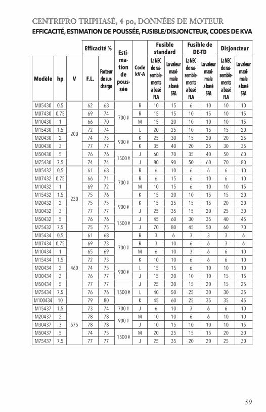
59
CENTRIPRO TRIPHASÉ, 4 po, DONNÉES DE MOTEUREFFICACITÉ, ESTIMATION DE POUSSÉE, FUSIBLE/DISJONCTEUR, CODES DE KVA
Efficacité %Esti-ma-tion de
pous-sée
Code kV·A
Fusible standard
Fusible de DE-TD Disjoncteur
Modèle hp V F.L.Facteur de sur-charge
La NEC de ras-
semble-ments a basé
FLA
La valeur maxi-male a basé
SFA
La NEC de ras-
semble-ments a basé
FLA
La valeur maxi-male a basé
SFA
La NEC de ras-
semble-ments a basé
FLA
La valeur maxi-male a basé
SFA
M05430 0,5
200
62 68
700 #
R 10 15 6 10 10 10
M07430 0,75 69 74 R 15 15 10 15 10 15
M10430 1 66 70 M 15 20 10 10 10 15
M15430 1,5 72 74 L 20 25 10 15 15 20
M20430 2 74 75900 #
K 25 30 15 20 20 25
M30430 3 77 77 K 35 40 20 25 30 35
M50430 5 76 761500 #
J 60 70 35 40 50 60
M75430 7,5 74 74 J 80 90 50 60 70 80
M05432 0,5
230
61 68
700 #
R 6 10 6 6 6 10
M07432 0,75 66 71 R 6 15 6 10 6 10
M10432 1 69 72 M 10 15 6 10 10 15
M15432 1,5 75 76 K 15 20 10 15 15 20
M20432 2 75 75900 #
K 15 25 15 15 20 20
M30432 3 77 77 J 25 35 15 20 25 30
M50432 5 76 761500 #
J 45 60 30 35 40 45
M75432 7,5 75 75 J 70 80 45 50 60 70
M05434 0,5
460
61 68
700 #
R 3 6 3 3 3 6
M07434 0,75 69 73 R 3 10 6 6 3 6
M10434 1 65 69 M 6 10 3 6 6 10
M15434 1,5 72 73 K 10 10 6 6 6 10
M20434 2 74 75900 #
L 15 15 6 10 10 10
M30434 3 76 77 J 15 20 10 10 15 15
M50434 5 77 77
1500 #
J 25 30 15 20 15 25
M75434 7,5 76 76 L 40 50 25 30 30 35
M100434 10 79 80 K 45 60 25 35 35 45
M15437 1,5
575
73 74 700 # J 6 10 3 6 6 10
M20437 2 78 78900 #
M 10 10 6 6 10 10
M30437 3 78 78 J 10 15 10 10 10 15
M50437 5 74 751500 #
M 20 25 15 15 20 20
M75437 7,5 77 77 J 25 35 20 20 25 30

60
MOTEURS TRIPHASÉS DE 4 po Données électriques — 60 Hz, 3 450 r/minMOTEURS TRIPHASÉS DE 4 po Données électriques — 60 Hz, 3 450 r/min
À pleine charge Avec FS* A avec rotor Ligne à Modèle hp kW V FS* A W A W bloqué ligne (Ω)
M05430 0,5 0,37 1,6 2,9 600 3,4 870 22 4,1 à 5,2 M07430 0,75 0,55 1,5 3,8 812 4,5 1 140 32 2,6 à 3,0 M10430 1 0,75 1,4 4,6 1 150 5,5 1 500 29 3,4 à 3,9 M15430 1,5 1,1
200 1,3 6,3 1 560 7,2 1 950 40 1,9 à 2,5
M20430 2 1,5 1,25 7,5 2 015 8,8 2 490 51 1,4 à 2,0 M30430 3 2,2 1,15 10,9 2 890 12,0 3 290 71 0,9 à 1,3 M50430 5 3,7 1,15 18,3 4 850 20,2 5 515 113 0,4 à 0,8 M75430 7,5 5,5 1,15 27 7 600 30,0 8 800 165 0,5 à 0,6 M05432 0,5 0,37 1,6 2,4 610 2,9 880 17,3 5,7 à 7,2 M07432 0,75 0,55 1,5 3,3 850 3,9 1 185 27 3,3 à 4,3 M10432 1 0,75 1,4 4,0 1 090 4,7 1 450 26,1 4,1 à 5,1 M15432 1,5 1,1
230 1,3 5,2 1 490 6,1 1 930 32,4 2,8 à 3,4
M20432 2 1,5 1,25 6,5 1 990 7,6 2 450 44 1,8 à 2,4 M30432 3 2,2 1,15 9,2 2 880 10,1 3 280 58,9 1,3 à 1,7 M50432 5 3,7 1,15 15,7 4 925 17,5 5 650 93 0,85 à 1,25 M75432 7,5 5,5 1,15 24 7 480 26,4 8 570 140 0,55 à 0,85 M05434 0,5 0,37 1,6 1,3 610 1,5 875 9 23,6 à 26,1 M07434 0,75 0,55 1,5 1,7 820 2,0 1 140 14 14,4 à 16,2 M10434 1 0,75 1,4 2,2 1 145 2,5 1 505 13 17,8 à 18,8 M15434 1,5 1,1
460 1,3 2,8 1 560 3,2 1 980 16,3 12,3 à 13,1
M20434 2 1,5 1,25 3,3 2 018 3,8 2 470 23 8,0 à 8,67 M30434 3 2,2 1,15 4,8 2 920 5,3 3 320 30 5,9 à 6,5 M50434 5 3,7 1,15 7,6 4 810 8,5 5 530 48 3,58 à 4,00 M75434 7,5 5,5 1,15 12,2 7 400 13,5 8 560 87 1,9 à 2,3 M100434 10 7,5 1,15 15,6 9600 17,2 11000 110 1,8-2,2 M15437 1,5 1,1 1,3 2,0 1 520 2,4 1 950 11,5 19,8 à 20,6 M20437 2 1,5 1,25 2,7 1 610 3,3 2 400 21 9,4 à 9,7 M30437 3 2,2 575 1,15 3,7 2 850 4,1 3 240 21,1 9,4 à 9,7 M50437 5 3,7 1,15 7,0 5 080 7,6 5 750 55 3,6 à 4,2 M75437 7,5 5,5 1,15 9,1 7 260 10,0 8 310 55 3,6 à 4,2
* FS = facteur de surcharge
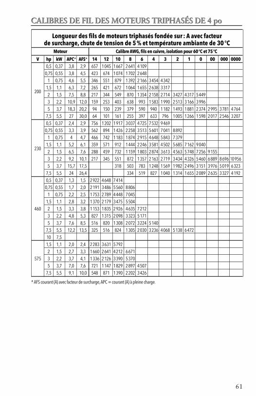
61
CALIBRES DE FIL DES MOTEURS TRIPHASÉS DE 4 poCALIBRES DE FIL DES MOTEURS TRIPHASÉS DE 4 po
Longueur des fils de moteurs triphasés fondée sur : A avec facteur de surcharge, chute de tension de 5 % et température ambiante de 30 °C
Moteur Calibre AWG, fils en cuivre, isolation pour 60 °C et 75 °C
V hp kW APC* AFS* 14 12 10 8 6 4 3 2 1 0 00 000 0000 0,5 0,37 3,8 2,9 657 1 045 1 667 2 641 4 109 0,75 0,55 3,8 4,5 423 674 1 074 1 702 2 648 1 0,75 4,6 5,5 346 551 879 1 392 2 166 3 454 4 342
200 1,5 1,1 6,3 7,2 265 421 672 1 064 1 655 2 638 3 317
2 1,5 7,5 8,8 217 344 549 870 1 354 2 158 2 714 3 427 4 317 5 449 3 2,2 10,9 12,0 159 253 403 638 993 1 583 1 990 2 513 3 166 3 996 5 3,7 18,3 20,2 94 150 239 379 590 940 1 182 1 493 1 881 2 374 2 995 3 781 4 764 7,5 5,5 27 30,0 64 101 161 255 397 633 796 1 005 1 266 1 598 2 017 2 546 3 207 0,5 0,37 2,4 2,9 756 1 202 1 917 3 037 4 725 7 532 9 469 0,75 0,55 3,3 3,9 562 894 1 426 2 258 3 513 5 601 7 041 8 892 1 0,75 4 4,7 466 742 1 183 1 874 2 915 4 648 5 843 7 379
230 1,5 1,1 5,2 6,1 359 571 912 1 444 2 246 3 581 4 502 5 685 7 162 9 040
2 1,5 6,5 7,6 288 459 732 1 159 1 803 2 874 3 613 4 563 5 748 7 256 9 155 3 2,2 9,2 10,1 217 345 551 872 1 357 2 163 2 719 3 434 4 326 5 460 6 889 8 696 10 956 5 3,7 15,7 17,5 318 503 783 1 248 1 569 1 982 2 496 3 151 3 976 5 019 6 323 7,5 5,5 24 26,4 334 519 827 1 040 1 314 1 655 2 089 2 635 3 327 4 192 0,5 0,37 1,3 1,5 2 922 4 648 7 414 0,75 0,55 1,7 2,0 2 191 3 486 5 560 8 806 1 0,75 2,2 2,5 1 753 2 789 4 448 7 045 1,5 1,1 2,8 3,2 1 370 2 179 3 475 5 504 460 2 1,5 3,3 3,8 1 153 1 835 2 926 4 635 7 212 3 2,2 4,8 5,3 827 1 315 2 098 3 323 5 171 5 3,7 7,6 8,5 516 820 1 308 2 072 3 224 5 140 7,5 5,5 12,2 13,5 325 516 824 1 305 2 030 3 236 4 068 5 138 6 472 10 7,5 1,5 1,1 2,0 2,4 2 283 3 631 5 792 2 1,5 2,7 3,3 1 660 2 641 4 212 6 671 575 3 2,2 3,7 4,1 1 336 2 126 3 390 5 370 5 3,7 7,0 7,6 721 1 147 1 829 2 897 4 507 7,5 5,5 9,1 10,0 548 871 1 390 2 202 3 426
* AFS courant (A) avec facteur de surcharge, APC = courant (A) à pleine charge.
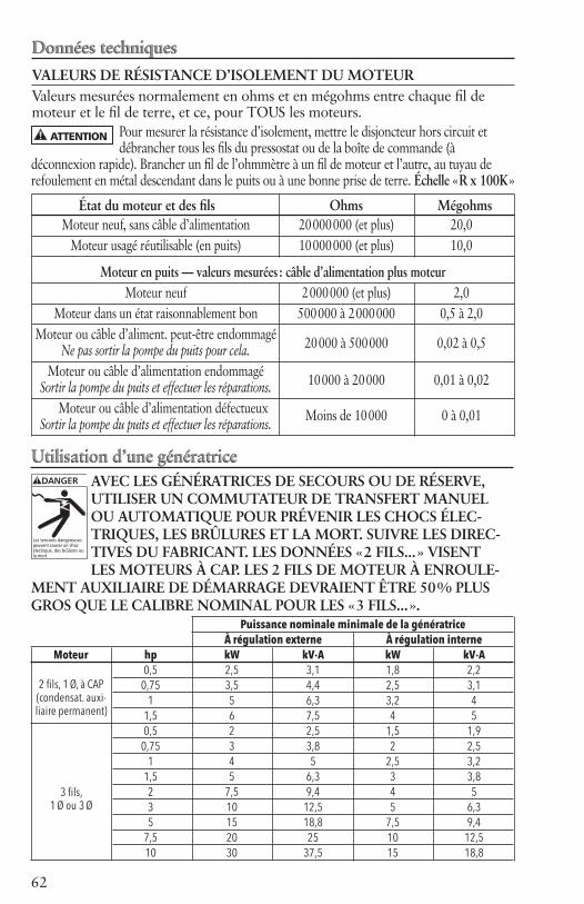
62
Données techniquesVALEURS DE RÉSISTANCE D’ISOLEMENT DU MOTEURValeurs mesurées normalement en ohms et en mégohms entre chaque fil de moteur et le fil de terre, et ce, pour TOUS les moteurs.
État du moteur et des fils Ohms Mégohms Moteur neuf, sans câble d’alimentation 20 000 000 (et plus) 20,0 Moteur usagé réutilisable (en puits) 10 000 000 (et plus) 10,0
Moteur en puits — valeurs mesurées : câble d’alimentation plus moteur Moteur neuf 2 000 000 (et plus) 2,0 Moteur dans un état raisonnablement bon 500 000 à 2 000 000 0,5 à 2,0 Moteur ou câble d’aliment. peut-être endommagé 20 000 à 500 000 0,02 à 0,5 Ne pas sortir la pompe du puits pour cela. Moteur ou câble d’alimentation endommagé 10 000 à 20 000 0,01 à 0,02 Sortir la pompe du puits et effectuer les réparations. Moteur ou câble d’alimentation défectueux Sortir la pompe du puits et effectuer les réparations. Moins de 10 000 0 à 0,01
Pour mesurer la résistance d’isolement, mettre le disjoncteur hors circuit et débrancher tous les fils du pressostat ou de la boîte de commande (à
déconnexion rapide). Brancher un fil de l’ohmmètre à un fil de moteur et l’autre, au tuyau de refoulement en métal descendant dans le puits ou à une bonne prise de terre. Échelle « R x 100K »
DANGER
Les tensions dangereusespeuvent causer un chocélectrique, des brûlures oula mort.
Utilisation d’une génératriceAVEC LES GÉNÉRATRICES DE SECOURS OU DE RÉSERVE,UTILISER UN COMMUTATEUR DE TRANSFERT MANUELOU AUTOMATIQUE POUR PRÉVENIR LES CHOCS ÉLEC-TRIQUES, LES BRÛLURES ET LA MORT. SUIVRE LES DIREC-TIVES DU FABRICANT. LES DONNÉES « 2 FILS... » VISENTLES MOTEURS À CAP. LES 2 FILS DE MOTEUR À ENROULE-
MENT AUXILIAIRE DE DÉMARRAGE DEVRAIENT ÊTRE 50 % PLUSGROS QUE LE CALIBRE NOMINAL POUR LES « 3 FILS... ».
Données techniques
Utilisation d’une génératrice
ATTENTION
Puissance nominale minimale de la génératrice À régulation externe À régulation interne Moteur hp kW kV·A kW kV·A 0,5 2,5 3,1 1,8 2,2 0,75 3,5 4,4 2,5 3,1 1 5 6,3 3,2 4 1,5 6 7,5 4 5 0,5 2 2,5 1,5 1,9 0,75 3 3,8 2 2,5 1 4 5 2,5 3,2 1,5 5 6,3 3 3,8 2 7,5 9,4 4 5 3 10 12,5 5 6,3 5 15 18,8 7,5 9,4 7,5 20 25 10 12,5 10 30 37,5 15 18,8
2 fils, 1 Ø, à CAP(condensat. auxi-liaire permanent)
3 fils, 1 Ø ou 3 Ø

63
DÉMARREURS TRIPHASÉS DE BUT DÉFINI AVEC DES SURCHARGES RÉGLABLES
Ordre de CentriPro Nº
Numéro de ré-férence d'Eaton
Maximum ampères
Tension d' alimentation
O.L. Relais
Chaîne de surcharge
Maximum LRA
Intervalle typique de HP
DP25D2 A27CGC25BA2P4
25 208-230
D 1.6-2.4
150 .5 - 5
DP25E2 A27CGC25BA004 E 2.4-4
DP25F2 A27CGC25BA006 F 4-6
DP25G2 A27CGC25BA010 G 6-10
DP25H2 A27CGC25BA016 H 10-16
DP25J2 A27CGC25BA024 J 16-24
DP25C4 A27CGC25CA1P6
25 460
C 1-1.6
125 .5 - 10
DP25D4 A27CGC25CA2P4 D 1.6-2.4
DP25E4 A27CGC25CA004 E 2.4-4
DP25F4 A27CGC25CA006 F 4-6
DP25G4 A27CGC25CA010 G 6-10
DP25H4 A27CGC25CA016 H 10-16
DP25J4 A27CGC25CA024 J 16-24
DP25E5 A27CGC25DA004
25 575
E 2.4-4
100 1.5 - 10DP25F5 A27CGC25DA006 F 4-6
DP25G5 A27CGC25DA010 G 6-10
DP25H5 A27CGC25DA016 H 10-16
DP30L2 A27CGE30BA010
30 208-230
L 6-10
180 1.5 - 7.5DP30M2 A27CGE30BA016 M 10-16
DP30N2 A27CGE30BA024 N 16-24
DP30P2 A27CGE30BA040 P 24-40
DP30L4 A27CGE30CA010
30 460
L 6-10
150 5 - 20DP30M4 A27CGE30CA016 M 10-16
DP30N4 A27CGE30CA024 N 16-24
DP30P4 A27CGE30CA040 P 24-40
DP30L5 A27CGE30DA010
30 575
L 6-10
120 5 - 15
DP30M5 A27CGE30DA016 M 10-16
DP30N5 A27CGE30DA024 N 16-24
DP30P5 A27CGE30DA040 P 24-40
DP30R5 A27CGE30DA057 R 40-57
DP40L2 A27CGE40BA010
40 208-230
L 6-10
240 1.5 - 10DP40M2 A27CGE40BA016 M 10-16
DP40N2 A27CGE40BA024 N 16-24
DP40P2 A27CGE40BA040 P 24-40
DP40L4 A27CGE40CA010
40 460
L 6-10
200 5 - 20DP40M4 A27CGE40CA016 M 10-16
DP40N4 A27CGE40CA024 N 16-24
DP40P4 A27CGE40CA040 P 24-40
DP40L5 A27CGE40DA010
40 575
L 6-10
160 5 - 20DP40M5 A27CGE40DA016 M 10-16
DP40N5 A27CGE40DA024 N 16-24
DP40P5 A27CGE40DA040 P 24-40
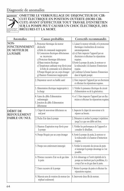
64
DANGER
Les tensions dangereusespeuvent causer un chocélectrique, des brûlures oula mort.
Diagnostic de anomaliesOMETTRE LE VERROUILLAGE DU DISJONCTEUR DU CIR-CUIT ÉLECTRIQUE EN POSITION OUVERTE (HORS CIR-CUIT) AVANT D’EFFECTUER TOUT TRAVAIL D’ENTRETIEN SUR LA POMPE PEUT CAUSER UN CHOC ÉLECTRIQUE, DES BRÛLURES ET LA MORT.
Anomalies Causes probables Correctifs recommandésNON-FONCTIONNEMENT DU MOTEUR DE LA POMPE
DÉBIT DE REFOULEMENT FAIBLE OU NUL
1. Protecteur thermique du moteur déclenché
a) Boîte de commande inappropriée b) Connexions électriques défectueuses
ou incorrectes c) Protecteur thermique défectueux d) Basse tension électrique
e) Température ambiante trop élevée pour la boîte de commande ou le démarreur f) Pompe bloquée par un corps étranger g) Hauteur d’immersion inappropriée
2. Disjonsteur ouvert ou fusible sauté
3. Alimentation électrique inappropriée à la charge
4. Gaine du câble d’alimentation endommagée
5. Jonction du câble d’alimentation défectueuse
1. Laisser le moteur refroidir, et le protecteur thermique s’enclenchera de nouveau automatiquement.
a) à e) Faire inspecter l’appareil par un électricien et effecttuer les réparations requises.
f) Sortir la pompe du puits, la nottoyer et la redescendre à la hauteur d’immersion requise.
g) Confirmer la bonne hauteur d’immersion dans le liquide pompé.
2. Faire inspecter l’appareil par un électricien et effectuer les réparations requises.
3. Vérifier la puissance électrique du circuit d’alimentation ou de la génératrice.
4. et 5. Faire inspecter l’appareil par un élec-tricien et effectuer les répararions requises.
1. Clapet de non-retour défectueux ou mal posé
2. Poche d’air dans la pompe
3. Hauteur d’aspiration trop élevée pour la pompe
4. Pompe bloquée par un corps étranger
5. Pompe non entièrement immergée
6. Présence excessive d’air ou de gaz dans le puits
7. Usure excessive de la pompe
8. Mauvais sens de rotation du moteur (en triphasé seulement)
1. Inspecter le clapet de non-retour et le réparer au besoin.
2. Démarrer et arrêter la pompe à répétition jusqu’à ce que son débit soit bon.
3. Vérifier les performances de l’appareil et consulter le détaillant.
4. Sortir la pompe du puits, la nettoyer et la redescendre à la hauteur d’immersion requise.
5. Vérifier la remontée du niveau du puits et immerger la pompe davantage si c’est possible.
6. Si le démarrage et l’arrêt répétitifs de la pompe ne résolvent pas le problème, il y a trop d’air ou de gaz dans le puits.
7. Retirer la pompe du puits et effectuer les réparations requises.
8. Intervertir deux fils du moteur.
Diagnostic de anomalies

65

66
GOULDS WATER TECHNOLOGY LIMITED WARRANTYThe warranty period for Goulds standard construction submersible pumps used with CentriPro motors and controls shall be thirty-six (36) months from date of installation or forty-two (42) months from date of manufacture, whichever period is shorter.Any part or parts found to be defective within the warranty period shall be replaced at no charge to the dealer during the warranty period. The warranty period for Goulds GS-CBM (aka GS Xtreme) pumps used with CentriPro motors and controls shall be thirty (30) days from date of installation or six (6) months from date of manufacture, whichever period is shorter.A dealer who believes that a warranty claim exists must contact the authorized Goulds Water Technology distributor from whom the pump was purchased and furnish complete details regarding the claim. The dis-tributor is authorized to adjust any warranty claims utilizing the Goulds Water Technology Customer Service Department.The warranty excludes:(a) Labor, transportation and related costs incurred by the dealer;(b) Reinstallation costs of repaired equipment;(c) Reinstallation costs of replacement equipment;(d) Consequential damages of any kind; and,(e) Reimbursement for loss caused by interruption of service.For purposes of this warranty, the following terms have these definitions:(1) “Distributor” means any individual, partnership, corporation, association, or other legal relationship that
stands between Goulds Water Technology and the dealer in purchases, consignments or contracts for sale of the subject pumps.
(2) “Dealer” means any individual, partnership, corporation, association, or other legal relationship which engages in the business of selling or leasing pumps to customers.
(3) “Customer” means any entity who buys or leases the subject pumps from a dealer. The “customer” may mean an individual, partnership, corporation, limited liability company, association or other legal entity which may engage in any type of business.
THIS WARRANTY EXTENDS TO THE DEALER ONLY.
GARANTÍA LIMITADA DE GOULDS WATER TECHNOLOGYEl periodo de garantía para las bombas sumergibles de construcción estándar Goulds utilizadas con motores y controles CentriPro será de treinta y seis (36) meses a partir de la fecha de instalación o cuarenta y dos (42) meses a partir de la fecha de fabricación, de los anteriores, el periodo que sea más corto.Toda parte o partes que resulten defectuosas dentro del período de garantía serán reemplazadas sin cargo para el comerciante durante dicho período de garantía. El periodo de garantía para las bombas Goulds GS-CBM (alias GS Xtreme) utilizadas con motores y controles CentriPro será de treinta (30) días a partir de la fecha de instalación o seis (6) meses a partir de la fecha de fabricación, de los anteriores, el periodo que sea más corto.Todo comerciante que considere que existe lugar a un reclamo de garantía deberá ponerse en contacto con el distribuidor autorizado de Goulds Water Technology del cual adquiriera la bomba, y ofrecer información detallada con respecto al reclamo. El distribuidor está autorizado a liquidar todos los reclamos por garantía a través del Departamento de Servicios a Clientes de Goulds Water Technology.La presente garantía excluye:(a) La mano de obra, el transporte y los costos relacionados en los que incurra el comerciante;(b) los costos de reinstalación del equipo reparado;(c) los costos de reinstalación del equipo reemplazado;(d) daños emergentes de cualquier naturaleza; y(e) el reembolso de cualquier pérdida causada por la interrupción del servicio.A los fines de esta garantía, los términos “Distribuidor”, “Comerciante” y “Cliente” se definen como sigue:(1) “Distribuidor” es aquel individuo, sociedad, corporación, asociación u otra entidad jurídica que opera
entre Goulds Water Technology y el comerciante para la compra, consignación o contratos de venta de las bombas en cuestión.
(2) “Comerciante” es todo individuo, sociedad, corporación, asociación u otra entidad jurídica que realiza negocios de venta o alquiler-venta (leasing) de bombas a clientes.
(3) “Cliente” es toda entidad que compra o que adquiere bajo la modalidad de leasing las bombas en cuestión de un comerciante. El término “cliente” puede significar un individuo, una sociedad, una corporación, una sociedad de responsabilidad limitada, una asociación o cualquier otra entidad jurídica con activida-des en cualquier tipo de negocios.
LA PRESENTE GARANTÍA SE EXTIENDE AL COMERCIANTE ÚNICAMENTE

67
GARANTIE LIMITÉE DE GOULDS WATER TECHNOLOGYLes pompes submersibles standard de Goulds munies d’un moteur et d’une commande CentriPro seront ga-ranties selon la période suivante expirant la première : trente-six (36) mois à compter de la date d’installation ou quarante-deux (42) mois à partir de la date de fabrication.
Toute pièce se révélant défectueuse sera remplacée sans frais pour le détaillant durant la période de garantie pertinente. Pour les pompes Goulds GS-CBM (les GS « Xtreme ») dotées d’un moteur et d’une commande CentriPro, cette période sera de (30) jours à partir de la date d’installation ou de six (6) mois à compter de la date de fabrication.
Le détaillant qui, aux termes de la présente garantie, désire effectuer une demande de règlement doit s’adresser au distributeur Goulds Water Technology agréé chez lequel la pompe a été achetée et fournir tous les détails à l’appui de sa demande. Le distributeur est autorisé à régler toute demande par le biais du service à la clientèle de Goulds Water Technology.
La garantie ne couvre pas :
a) les frais de main-d’œuvre ou de transport ni les frais connexes encourus par le détaillant ;
b) les frais de réinstallation de l’équipement réparé ;
c) les frais de réinstallation de l’équipement de remplacement ;
d) les dommages indirects de quelque nature que ce soit ;
e) ni les pertes découlant de la panne.
Aux fins de la garantie, les termes ci-dessous sont définis comme suit :
1) « Distributeur » signifie une personne, une société de personnes, une société de capitaux, une association ou autre entité juridique servant d’intermédiaire entre Goulds Water Technology et le détaillant pour les achats, les consignations ou les contrats de vente des pompes en question.
2) « Détaillant » veut dire une personne, une société de personnes, une société de capitaux, une association ou autre entité juridique dont les activités commerciales sont la vente ou la location de pompes à des clients.
3) « Client » signifie une entité qui achète ou loue les pompes en question chez un détaillant. Le « client » peut être une personne, une société de personnes, une société de capitaux, une société à responsabilité limitée, une association ou autre entité juridique se livrant à quelque activité que ce soit.
LA PRÉSENTE GARANTIE SE RAPPORTE AU DÉTAILLANT SEULEMENT.

Goulds is a registered trademark of Goulds Pumps, Inc. and is used under license. Goulds es una marca registrada de Goulds Pumps, Inc. y se utiliza bajo licencia. Goulds est une marque déposée de Goulds Pumps, Inc. et est utilisé sous le permis.© 2012 Xylem Inc. IM096 Revision Number 7 July (Julio/Julliet) 2012
Xylem, Inc.2881 East Bayard Street Ext., Suite ASeneca Falls, NY 13148Phone (Teléfono/Téléphone): (866) 325-4210 Fax (Télécopie): (888) 322-5877www.xyleminc.com/brands/gouldswatertechnology


