23
40YEARSOFCONTINUOUSINNOVATION

40 YEARS OF CONTINUOUS INNOVATION

www. garniga. com
1% INFORMAZIONI TECNICHEW TECHNICAL INTRODUCTIONi/ INFORMACIONES TECNICASI/ TECHNISCHE INFORMATIONEN
TECNICA COSTRUTTIVA DEGLI UTENSILI DI FRESATURAWoodworking tools manufacturing engineering Tecnica constructiva del utensilio para fresadoKontruktionstechnik der Fraswerkzeuge
SISTEMI DI FISSAGGIO Knives fixing system Sistema de fijacion Fixiersysteme
RAGGIATORI - SETTORI - INCISORI Radiusing inserts - Toothed Sectors - SpursRadios - Sectores - Incisores Radien - Zahnsegmente - Vorschneider
NORMATIVE DI SICUREZZA MAN & MEC Safety norms Man & MecNormativa de seguridad Man & Mec Sicherheitsvorschriften Man and Mec
INFORMAZIONI UTILI PER LA LAVORAZIONE DEL LEGNOUseful information woodworking processInformacion util para la elaboracion de la maderaNutziiche einsatzbedingugen for die holzbearbeitung
GRADO DI FINITURA E VELOCITA' DI AVANZAMENTO Finish quality and feed ratesGran acabado y velocidad de avance Oberflachengute and vorschubgeschwindigkeit
Z
pag.003
pag.005
pag.007
pag.011
pag.013
pag.015
DIAGRAMMA PER LA SCELTA DELLA VELOCITA DI AVANZAMENTO Diagram for choosing thefeeding speed Diagrama para la eleccion de la velociada de avance Diagramm for diebestimmung des vorschubgeschwinddigkeit
pag.019
DIAGRAMMA PER LA SCELTA DEL NUMERO DI GIRT Diagram for choosing the number ofrevolutions Diagrama para la eleccion de numero de giros Diagramm for die bestim-mung der drehzahl
pag.020
ROTAZIONE Rotation Rotation Drehrichtungpag.021
ra vV y
•
•S
~C.2
F F
CIOW v=C.2 =u. WW ~F CIO•
W
N vC Q
C CO•O
W
•
S
002

ra 5e 22= =W WF H
MW C~7Z -.i vu. WW ~H N- WO ON C7C CC CO OLL. LL.
003
TECNICA COSTRUTTIVA DEGLI UTENSILI DI FRESATURAWoodworking tools manufacturing engineeringTecnica constructiva del utensilio para fresadoKontruktionstechnik der Fraswerkzeuge
UTENSILI PER AVANZAMENTO MANUALEManual feedin toolsUtensilio para avance de la manoHandvorschub-Werkzeuge
manuale
GRUPPO DI UTENSILI REGOLABILIAdjustable set of toolsGrupo de utensilio regulableVerstellbare Werkzeugsatze
GRUPPO DI UTENSILI SPINATI
Set of tools locked together by pinsGrupo de utensilio con PINS de arrastreGestifteter Werkzeugsatz
UTENSILI PER AVANZAMENTO AUTOMATICOMechanical feeding toolsUtensilio para avance automaticoMechanischer Vorschub-Werkzeuge
GRUPPO DI UTENSILI SU CANOTTO A FLANGIABLOCCATA PER MEZZO DI GHIERASet of tools mounted on a sleeve with lock nutsGrupo de utensilio Montado sobre canuto y Bloqueadopor medio de tuercas
Werkzeugsatz auf HUlse mit Nutmutter Blockierflansch
GRUPPO DI UTENSILI NON SPINATI
Set of Tools not locked by pinGrupo de utensilio sin PINS de arrastreUngestifteter Werkzeugsatz
Nw/ (ARNICA

COLTELLI A 35° E 45°Carbide inserts with 35° and 45°Cuchillas con 35° y 45°Hw-Wendeschneiden 35° and 45°
Per migliorare it rendimento degli utensili, in determinate situazioni, Garniga utilizza coltelli Eurosystem the possonoavere un angolo di spoglia di 35 0 o 45° . L'utensile nasce con caratteristiche costruttive diverse a seconda the debbaospitare coltelli a 35° o 45°. E' quindi importante the I'utilizzatore conosca it coltello montato sul suo utensile perevitare di sostituire i coltelli con tipologie differenti da quelle per le quali a stato progettato .Per riconoscere se it coltello ha 35° o 45° di spoglia a sufficiente guardare le misure come indicato nel disegno
To improve tool efficiency according to necessity, Garniga uses carbide inserts with 35° or 45° cutting angle . This requires differentconstruction geometry of the tool . It is therefore very important that the user knows which inserts are used . Please see details ondrawing below
Para mejorar el rendimiento del utensilio, en determinadas elaboraciones, Garniga, utiliza cuchillas Eurosystem, que posiciona conun angulo de corte de 350 o de 45 0 . El utensilio, creado con caracteristicas constructivas diversas segun deba montar cuchilla de350 o 450 . Esto es importante que el usuario conozca la cuchilla montada sobre su utensilio para evitar el sustituir la cuchilla contipologia diferente de acuerdo a aquello que esta proyectado . Para reconocer la cuchilla de 35a o 45 0 es suficiente mirar la medidacomo esta indicada en el diseno
Um die Effizienz der Werkzeuge je nach Anwendung zu verbessern, verwendet Garniga HW-Wendeschneiden mit 35° oder 45°Schnittwinkel. Dies bedingt einen konstruktivenUnterschied beim Werkzeug . Es ist deshalb wichtig, daB der Anwender dieverwendeten HW-Wendeschneiden erkennt and korrekt ersetzt .Details entnehmen Sie bitte aus der nachfolgenden Zeichnung
7
1 .5
19
2.2
G)7
1.5
~/ G°"CA
Wz 0z~HC CW ~•
zz Wxa vv vsz zxxV CW W•
I -
caW RC.7xw_ zz Cu. WW ~•
NWz z
C C~ L
004

ZWZ Z•
oC•a
e ca•
• L1x -~_ WV yZ Z
e lI- I-
yW vSv ZZ vu. WW ~F NWZ ZN v•
• 0
005
SISTEMI DI FISSAGGIOLa migliore macchina puo rendere tanto quanto rende it tagliente col quale a realizzata . Infatti a proprio it tagliente a svolgereit lavoro sul legno . I taglienti possono essere collegati in modo insolubile con it corpo rotante oppure possono essere montatisul corpo mediante elementi di fissaggio staccabili .Nel primo caso ogni singolo utensile puo essere impiegato soltanto per itsingolo profilo : ogni altra forma di profilo richiede un suo utensile . E dovendo lavorare tipologie di legno particolarmentediversificate, per le quali sono richieste taglienti composti da diversi materiali, per to stesso profilo deve essere ordinata unafresa supplementare . Inoltre, volendo riaffilare i taglienti, dato it necessario angolo di spoglia sul dorso dell' utensile, vienealterato it profilo stesso .Nel secondo caso invece, i taglienti possono essere cambiati in ogni momento, con I'indiscusso vantaggio the con to stessocorpo portante dell' utensile a possibile eseguire molteplici profili su differenti tipologie di legno .Garniga a stata la prima ditta ad introdurre questa importante innovazione, delta fissaggio meccanico e piu in particolare intutti questi anni di ricerca ed innovazione ha approntato una variety di sistemi di fissaggio dei taglienti the consentono lemigliori prestazioni in relazione al tipo di coltello utilizzato e alla lavorazione da eseguire
KNIVES FIXING SYSTEMSThe quality of the manufacturing process with even the best machines available to the market, is always strictly connected to thequality of the knives used on it . As a matter of fact it is the knife that cuts the wood . Knives can be brazed to the tool or can be fixedby using detachable fixing systems . Using the first method each tool can be used for only one single profile : this means, to obtaindifferent profiles it would be necessary to use different tools, a tool for each type of profile . Furthermore, machining different solidwoods or man made board requires knives that are made of different materials to achieve optimum finishes and longevity .Consequently the user will have to order an additional tools according to the type of materials to be machined just to make the sameprofile . Last but not least, if he wants to regrind the knives, You have to consider that to maintain the tooth angle (hook) on the tool,the profile will change .By using a detachable fixing system, not only it is possible to change knives whenever it is required but you have the advantage toobtain many different profiles on various kinds of wood only using the same tool body .Garniga was the first company to introduce such an important innovation, by using a mechanical fixing system, and as a result of acontinuous research we have developed a variety of different fixing systems that enables us to always obtain the best performanceaccording to the type of application and knife used
SISTEMA DE FIJACIONLa mejor maquina puede rendir todo to que debe de rendir el diente que es el cual to realiza . En cuanto al propio cortante es el quetrabaja sobre la madera . El diente puede ser montado de modo soldable con el cuerpo rotante o tambien puede ser montado el cuerposobre un elemento de fijacion desmontable . En el primer caso el utensilio, al estar soldado tiene un simple perfil : En contra de la otraforma el perfil reside en el utensilio . Y depende de la tipologia de madera a trabajar se monta cualquier tipo diverso de material de lacuchilla, por to tanto debe de ordenar una fresa suplementaria . En cambio, este elemento debe ser reafilado dando angulo necesariode corte sobre el cuerpo del utensilio, por este caso, se alteraria el angulo .En es segundo caso, el diente pasa a ser intercambiable en todo momento, con incluso ventaja con el otro que el cuerpo cortante delutensilio es posible de conseguir multiplicar los perfiles y los diferentes tipos de madera .Garniga es la primera firma en introducir esta importante innovacion, de fijar mecanicamente y mas en particular en todos estos anosde experiencia e innovacion ha aportado una variedad de sistema de fijacion del diente que en consecuencia ha mejorado lasprestaciones en la realizacion del tipo de cuchilla utilizada dependiendo de la elaboracion a conseguir
FIXIERSYSTEMEDie Arbeitsleistung der besten Holzbearbeitungsmaschinen ist abhanig von der Qualitat der eingesetzten Schneiden, die eigentilich dieSchneidarbeit leisten .Die Schneiden konnen entweder ungelost vom Tragkorper sein oder auf dem Tragkorker mittels abnehmbaren Fixierelemente befestigtwerden. Im ersten Fall kann das Werkzeug nur fur einen einzelnen Profil verwendet werden : jede verschiedene Profilanderung verlangteinen spezifischen Werkzeug .Da verschiedene Holzarten verarbeitet werden, mussen fur denselben Profil Schneiden aus verschiedenen Materialien eingesetztwerden and folglich fur denselben Profil muB ein zusatzliches Wekzeug bestellt werden . Weiterhin bei der Scharfung der Schneidenwird das Profil, auf Grund des Seitenspanwinkels, verandert .Im zweiten Fall konnen die Schneiden im jeden Moment ausgetauscht werden mit dem unbestrittenen Vorteil, daB mit demselbenWerkzeugkorper verschiedene Profile, fur die verschiedensten Holzarten, montiert werden .Garniga hat als erstes Unternehmen dieses wichtige Erneuerungssytem eingesetzt, das auch unter dem Begriff mechanischesFixiersystem weit bekannt ist . Vor allem in diesen Jahren, Dank der kontinuierlichen Forschung and Erneuerung hat Garnigaverschiedene Schneide-Fixiersysteme bereitgestellt um, mit Bezug auf die eingesetzten Messer and Holzverarbeitung,hochleistungsgsfahige Ergebinisse zu erreichen
~/ G°"CA

I PRINCIPALI SISTEMI DI FISSAGGIO ATTUALMENTE IN USO IN FUNZIONE DEL TAGLIENTE DA UTILIZZAREThe main fixing systems we use in relation to the type of knives usedPrincipales sistemas de fijacion actuales en funcion del use de la cuchilla a utilizarWichtige Fixiersysteme and zugehorige Schneiden
MATERIALE
TIPOLOGIA
Type
Tipologia
TO
SPESSORE mm .BULLDOZER-N
G-LOCKLIMITER
LIMITER PIATTABANDAPIALLE TRADIZIONALI-N
TRADIZIONALETRADIZIONALE CON
CONTROFERRO
TRADIZIONALESAGOMATO
ULTIMATE FIXUNIFIX PROUNIFIX TS
ZIGRO
HM
EUROSYSTEM
Eurosystem
Eurosystem
Eurosystem
1,5 a 2,2
HM
SAGOMATI
Profiled
Perfiladas
Profilmesser
2,0/3,0
HMSAGOMATICON CAVA
Profiled withrear groove
Perfiladas conranura
Profilmessermit Hinternut
5,0
HM/HSSBULLDOZERCON CAVA
Bulldozer withrear groove
Bulldozer
Bulldozer mitHinternut
HSSSAGOMATICON CAVA
Profiled withrear groove
Perfiladas conranura
Profilmessermit Hinternut
5,0
HSS
ZIGRINATI
Serrated
Ranugada
RiickenverzahnteMesser
8,0/10,0
HSS/H M
PER PIALLE
For planningheads
Para cabezal
Fur Obelkopfe
3,0
~/ G°"CA
WZ =H
LLL
Z Wr SC V52 MZ ZS•
WOW W
F F
MW .S R..7.7•
Zs C7u. WW ~H NWZ =O O•
VC CC C•
OL16 L16
006

WZ =•
0C•a
•
• ~•
6LL•
Wr Ea VV yZ Z•
Sl lW WF I-
CIOW vS•
== Vu. WF~ WZ ZN Z;C QC C•
•
OW
007
RAGGIATORI - SETTORI - INCISORII componenti Garniga sono progettati per finire, raggiare, smussare .Gli inserti eliminano gli spigoli vivi dai corpi lavorati, garantendo migliore quality estetica e migliore riuscita deltaverniciatura. Possono essere montati su sede fissa o regolabile, consentendo, in questo caso, di ottenere battute di altezzadiversa .Analogamente, anche i settori dentati, utilizzati per realizzare sedi di altezza ridotta, possono essere montati su sede fissae mobile . Disponibili nella versione "Saldobrasati" o "Con limitatore", si distinguono in tipo lungo e corto .Per quanto riguarda gli incisori Garniga, questi consentono una finitura perfetta e senza rigature, garantita dall' ampiagamma di scelta di elementi, in cui ciascuno a progettato per soddisfare le piu diverse esigenze
RADIUSING INSERTS - TOOTHED SECTORS - SPURSGarniga knives are designed to finish, radius and bevel .Radiusing inserts eliminate the sharp edges and guarantee a better aesthetic quality and result when painting . They can beplaced on a fixed or adjustable position, the last permitting to obtain rebates of different heights .Similarly the toothed sectors, used to make grooves of a small width, can be placed either by a fixed or adjustable position .Available as a "brazed type" or as a version "with limiters", they are distinguished between short and long type .With regards to Garniga spurs, they make a perfect finish without splintering the material and a variety of spurs are availablethat satisfies the most difficult needs of the application
RADIOS - SECTORES - INCISORESLos componentes Garniga estan disenados para la terminacion, radios, biseles . Con los insertos montados sobre el cuerpode trabajo, garantiza tanto la calidad estetica y mejora el poder de trabajo . Pueden ser montados en sedes fijas o regulables,consintiendo que en este caso obtener trabajos en diversos gruesos . Analogicamente, antes, los sectores dentados serealizaban en la sede con altura predispuesta, hemos pasado a montar esta sede fija a movil .Disponible en la version (Con limitador) y distinguido el tipo corto o largo .Por cuanto depende del incisor Garniga, este consigue una terminacion perfecta sin astillado que garantiza nuestra ampliagama de elementos y con ello podremos sofisticar los proyectos mas diversas exigencias
RADIEN - ZAHNSEGMENTE - VORSCHNEIDERDie Garniga Bestandteile sind fir Finishing, Radien and Abfasen entwickelt .Die Einsatze dienen zur Entfernung von Scharfkanten and garantieren damit bessere asthetische Qualitat and bessereLackierung . Die Einsatze konnen auf Fest- bzw . verstellbare Sitze montiert werden, in diesem Fall sind Anschlageverschiedener Hbhe erreichbar.Folglich auch die Zahnsegmente konnen auf Fest- bzw . verstellbare Sitze montiert werden . Es existieren zwei Versionen :besti ckt oder mit Spanbegrenzer and these unterscheiden sich hauptsachlich in die Lange and werden als ,kurz-" oder„fang-Version" benannt .Die Vorschneider ermoglichen eine perfekte and rillenlose Oberflachengute, garantiert durch die weite Auswal derangebotenen Elemente, wobei jedes Vorschneider fur die Erfullung der verschiedensten Forderungen entwickelt wird .
www.garniga.comR
Nw/ GARNICA
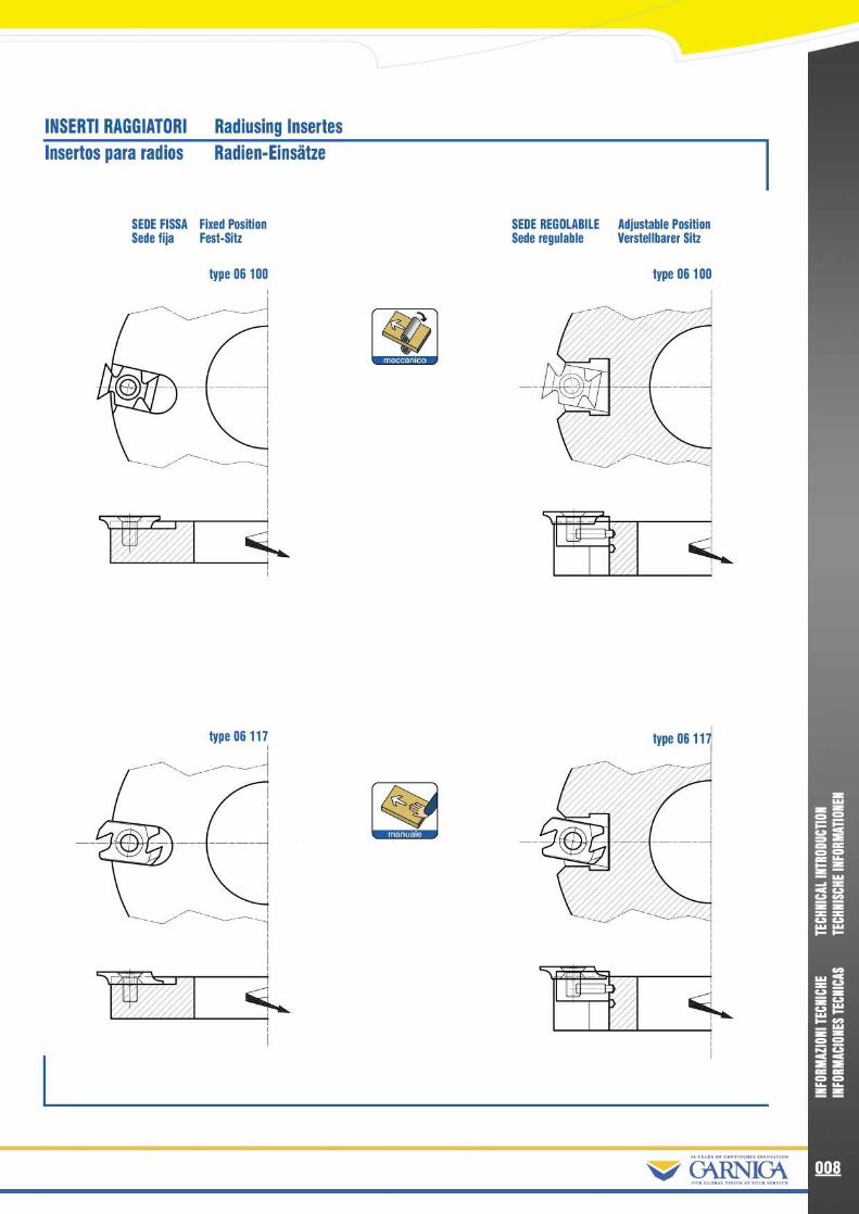
INSERTI RAGGIATORI
Radiusing InsertesInsertos para radios
Radien-Einsatze
SEDE FISSA Fixed PositionSede fija
Fest-Sitz
type 06 117
Z R manuals
SEDE REGOLABILE
Adjustable PositionSede regulable
Verstellbarer Sitz
type 06100
No/ GARNICA
ZWsoO O
F ZWr SC VV MZ ZS S• C lW WF F
MW RZ.7S•
ZZ Ou. WF~ WZ ZO O•
VC CC C•
OZ Z
008

WZ =•
O
e• =•
• 0z W1 mC Vv yr
m•m
W•W
F f-
caW MCSv =u. WW ~H NW
Z =O O• VC C
C CO O
009
SETTORI DENTATI Toothed Sector Sectores dentados Zahn-Segment
SALDOBRASATI Brazed TypeElectrosoldado Bestuckt
type 06 107,
TIPO CORTO - SEDE FISSAShort Type on a Fixed Position
Tipo corto - Sede fijaKurz-Version auf festem Sitz
TIPO LUNGO - SEDE FISSALong Type on a Fixed Position
Tipo Largo - Sede fijaLang-Version auf festem Sitz
TIPO CORTO - SEDE REGOLABILEShort Type on an Adjustable Position
Tipo corto- Sede regulableKurz-Version auf verstellbarem Sitz
CON LIMITATORE With LimiterCon limitador
Mit Spanbegrenzer
res
Ev:
~-waiii
type 06 118
~/ (ARNICA

COLTELLI SOTTILI Thin Knives Coltelli Sottili Diinne Messer
INCISORI Spurs Incisores Vorschneider
QUADRATI SOTTILI Thin squareCuadrado fino
Dunne Vierkant-Vorschneider
14X14X1,2
TRIANGOLARI TriangularTriangular
Dreikant-Vorschneider
22x19x2
RAGGIATI RadiusRadios
Radius-Vorschneider
QUADRATI SquareCuadrado Vierkant-Vorschneider
RAGGIATI RadiusRadios
Radius-Vorschneider
type 06100
type 06100
~/ GARNICA
ZWsoZ~HZ•
CWF• ZZ Wr S
s zxx•
asW WH F
MW RZ.7S•
ZZ Ou. WW ~H NWZ ZO O•
CDC CC CO OZ Z
010

WZ =•
OF• CCC C•
Oa.-• W- 5V yZ ZllW WI- I-
yW vu. WW ~~ WZ ZN v•
• O
01 1
NORMATIVE DI SICUREZZA MAN & MECA causa dell' alto numero di giri e dei taglienti molto affilati, gli utensili per la lavorazione del legno possono presentaredei rischi d' utilizzo soprattutto se vengono costruiti in modo non conforme a/o utilizzati in modo improprio .In tema di sicurezza la Garniga opera secondo le direttive della normativa Europea EN 847/1 . Tale normativa identifica tuttii pericoli the derivano da un'errata progettazione ed uno scorretto use degli utensili . Essa descrive inoltre i metodi per laloro riduzione ed eliminazione mediante un accurato studio in fase di progettazione .Per questo motivo Garniga, da sempre attenta e consapevole sostenitrice dell' importanza del terra della sicurezza nelmondo del lavoro :•
Contrassegna tutti i propri utensili in modo indelebile con it proprio logo e la massima rotazione al minuto ammessa, laquale non deve essere mai superata .
•
Marchia in maniera indelebile su tutti i propri utensili it logo "MAN" o "MEC" the identifica I' appartenenza alle seguenticategorie :
manuale
meccanico
manuale
meccanico
It is highly recommended to read the operating instructions carefully, before using the tools
Indica the l'utensile puO essere utilizzato per lavorazioni con avanzamenti manuali . Infatti, tale utensilesoddisfa le seguenti caratteristiche :- Spessore truciolo limitato al massimo a 1,1 mm- Possibilmente forma circolare- Apertura per truciolo limitataComunque non a vietato inserire tali utensili anche su macchine ad avanzamento meccanico, peril datoto spessore del truciolo limitato, viene necessariamente limitata anche la velocity di avanzamento .
Indica the l'utensile puo essere utilizzato solo per lavorazioni con avanzamenti meccanici . In questocaso non a richiesta limitazione dello spessore del truciolo e la forma di costruzione puo essere inesecuzione aperta . Dato it pericolo di contraccolpo, gli utensili previsti per ('avanzamento meccanicosono vietati per I'uso con altri tipi di avanzamento .
Prima di procedere alla lavorazione, a comunque consigliato osservare le norme prescritte dalle istruzioni d'uso fornite
SAFETY NORMS MAN & MECBecause of the high rotation and very sharp edges of the cutting knives, the woodworking tools can be dangerous if usedimproperly or produced not in compliance with the safety norms .In terms of safety Garniga manufactures according to the EN 847/1 European Norm . This Norm identifies all risks causedby a wrong design and improper tools' use . It also describes how to reduce and avoid these risks by means of a detailedand accurate study during the design process .For this reason Garniga that has always been aware of the importance of the safety norms :•
Mark all tools in an indelible way with the company logotype and with the maximum tool's rotation speed per minuteallowed that should never be exceeded .
•
Mark all tools in an indelible way with the "MAN" or "MEC" logotype, which identifies to which category each tool belongsto :
That means the tool can be used on manual feed operation .It also has the following features :- Limited chips thickness to a maximum of 1,1 mm- If possible it has a circular shape- Limited cutter projection- Two forms of fixing "ie wedge and a pin"Please note that these tools can also be used on mechanical feed operations but it is necessary to limitthe feed speed because of the limited chips' thickness .
That means the tool can be used exclusively on mechanical feed operation . Consequently a limit to thechips' thickness is not needed and it could have a non round form (without a chip limitation) .Due to the high risk of kicks, it is forbidden to use mechanical feeding tools on different kinds of feeding .
~/ GARNICA

NORMATIVA DE SEGURIDAD MAN & MECA causa del alto numero de vueltas y de los dientes muy afilados, el utensilio para la elaboracion de la madera, pasa apresentar sobre el pedido de utilizacibn sobre todo, en beneficio del modo de construir no conforme y no utilizar el modoimpropio .Dentro del tema de seguridad, la Garniga opera segGn las directivas de la Normativa Europea
EN847/1 . Tal normativa,identifica todos los pedidos que se derivan de una proyeccibn cerrada y de un mal use del utensilio .Esto describe en nuestro metodo para la reducciOn y la eliminacibn mediante un minucioso estudio en base al proyecto .Por este motivo, Garniga, esta siempre atenta y consecuente sosteniendo la importancia del tema de la seguridad en elmundo del trabajo :•
Estampando a todos los utensilios de modo legible con el propio logo de la maxima rotaciOn al minuto la cual no debesuperar.
•
Marcado de manera que todos los utensilios con el logo "MAC b MEC" que identifica que es de la siguiente categoria :
manuale
41meccanico
Antes de proceder a trabajar observar la norma prescrita en las instrucciones de use por el fabricante
SICHERHEITSVORSCHRIFTEN MAN & MECWerkzeuge fir Holz- und Kunststoffbearbeitungen arbeiten oft mit hohen Schnittgeschwindigkeiten und, je nachDurchmesser, in hohen Drehzahlbereichen, entsprechend grog sind daher die Anforderungen an ihre Konstruktion undfir ihr geignetes Gebrauch . Die Garniga-Werkzeuge entsprechen der Sicherheitsnorm EN 847/1 . Diese Norm ermitteltalle Gefahren die von einem mangelnde Werkzeugentwurfes bzw . mangelndem Werkzeugeinsatz verursacht werden undbeschreibt die Methoden um diese Gefahren zu vermindern und lurch eine sorgfaltige Arbeit in der Entwicklungsphasedes Werkzeuges zu vermeiden . Die Sicherheit der Werkzeuge bei der Holzbearbeitung ist fir Garniga ihr oberstes Gebotund daher markiert Garniga die eigenen Werkzeuge mit :•
Unausloslichem Garniga Logo und mit Angabe des max . zugelassenen Drehzahlbereiches pro Minute, der niemalsi berschnitten werden muB .
•
Unausloslichem Logo MAN oder MEC wodurch die Zugehbrigkeit der Werkzeuge an folgende Werkzeuggruppenkennzeichnet :
Cmanuale
meccanico
Indica que este utensilio puede ser utilizado para trabajos con avance manual . Significa que talutensilio tiene las siguientes caracteristicas :- Espesor de corte limitado al maximo de 1 .1 mm- Posibilidad de forma circular- Apertura de corte limitadaAunque no esta prohibido montar este utensilio en su maquina de avance mecanico, pero dado elespesor de trabajo limitado, viene necesariamente limitada la velocidad de avance .
Indica que este utensilio puede ser utilizado solo para elaboraciones con avance mecanico . En estecaso, no necesita limitador de espesor de corte y la forma de construir puede ser en ejecuciOnabierta . Dado el peligro de contrastillar, el utensilio esta previsto para avance mecanico, estaprohibido para el use de otro tipo de avance .
Das Werkzeug kann fir Bearbeitungen mit Handvorschub verwendet werden und erfi llt folgendeMerkmale :Spandickenbegrenzung auf hochstens 1,1 mmWeitgehend kreisrunde FormBegrenzte Spanli ckenweite
Es ist nicht verboten diese Werkzeuge auf Maschinen mit mechanischem Vorschub einzusetzen, aberauf Grund der Spandickenbegrenzung muB folglich auch die Vorschubgeschwindikteit begrenzt werden .
Das Werkzeug kann nur fur Verarbeitungen mit mechanischem Vorschub eingesetzt werden .In diesem Fall wird die Spandickenbegrenzung nicht verlangt und die Form kann offen sein . AufGrund der Ri ckschlaggefahr ist der Einsatz von Werkzeugen mit mechanischem Vorschub fi randere Vorschubarten verboten .
Vor dem Einsatz wird die Einhaltung der Vorschriften der beigefi gten Anwendungsangaben empfohlen
yW vSV =•
Vu. WW ~~•W
N v
•
• 0_ _
01 2(ARNICA

- 5V•y
W• WI- I-
yW• v•
vu. WW ~F CIO•
W
N vC Q
W••U
01 3
INFORMAZIONI UTILI PER LALAVORAZIONE DEL LEGNO
LAVORAZIONE CONCORDE 0 CONTRARIA ALLAVANZAMENTO1 .CONTRARIA ALL AVANZAMENTOE' it sistema piu usato dove l'utensile ruota controI'avanzamento del legno e si ottiene un truciolo lungocon spessore crescente .
VANTAGGI Lunga durata dei taglienti grazie allafavorevole condizione di lavoro .SVANTAGGI Nelle lavorazioni contro venatura possonoverificarsi scheggiature .NB : a it solo sistema possibile con I'avanzamentomanuale .
2.CONCORDE ALL AVANZAMENTOL utensile ruota in concordanza con I' avanzamento dellegno e presenta un truciolo corto con sezionedecrescente .
VANTAGGI Buona finitura anche in condizioni sfavore-voli alla disposizione delle fibre . Avanzamento conminore sforzo .Possibility di maggiore avanzamento a parity di finitura .SVANTAGGI Minore durata dei taglienti a causa delmaggiore tempo di contatto del tagliente col legno .Nota: lavorazione possibile solo con I'avanzamentomeccanico .
DIREZIONE DI TAGLIO NELLA LAVORAZIONE DELLEGNO1 . TAGLIO LUNGO VENAA . CON LA VENATURA Lavorazione facile - Buonaquality della superficie ; possibile I'avanzamento veloce .B. CONTRO LA VENATURA Lavorazione difficoltosa acausa di scheggiature . Questa direzione di taglioandrebbe possibilmente evitata cambiando la lavora-zione, invertendo per esempio it senso di lavorazione
2. TAGLIO ATTRAVERSO VENALavorazione leggera, tuttavia superficie leggermenteruvida
3. TAGLIO DI TESTA (FRONTALE)Le fibre vengono tagliate verticalmente . Elevata forza ditaglio . Lavorazione difficile . Superficie relativamenteruvida a causa della rottura delle fibre . E' possibile soloun avanzamento lento .
\/ USEFUL INFORMATION ONWOODWORKING PROCESS
CUTTING AGAINST OR IN DIRECTION OF FEED1 . AGAINST DIRECTION OF FEEDThis is the most common method of cutting, whichproduces a long chip with a rising thickness .
ADVANTAGES Long performance and knives' durabilitybecause the geometrical angle is favourable and powerrequirements are at minimum .DISADVANTAGES When cutting in the opposite way of thegrain it is possible to obtain a rough surface finish andsplinters .Please note : This woodworking process is only possibleby a manual type feed .
2. IN DIRECTION OF FEEDThe tools' sense of rotation is in the same direction of thefeed and this produces a short chip with a decreasingthickness .
ADVANTAGES Good surface finish even when the positionof the grains is not favourable . Less feeding thrust . Fasterfeed speed .DISADVANTAGES Reduced knives' life duration due to alonger contact with the wood .Please note : This woodworking process is only possibleby a mechanical type feed . As there are inherent dangerswith this method .
CUTTING DIRECTION IN THE WOODWORKING PROCESS1 . ALONG THE GRAINA. IN THE GRAIN'S DIRECTION Easy working . Goodsurface finish ; it is possible a fast feeding speed .B. OPPOSITE TO THE GRAIN'S DIRECTION Difficultworking due to splinters . This cutting direction could beavoided by simply changing the working direction .
2. ACROSS THE GRAIN Easy working but a slight roughsurface finish .
3. END GRAIN (FRONTAL) Fibres are cut vertically . Highshearing force . Difficult working . Slight rough surfacefinish caused by the fibres breaking . It is possible only aslow feeding .
~/ G°"CA

7INFORMACIUN UTIL PARA LAELABORACION DE LA MADERA
TRABAJOS A FAVOR 0 EN CONTRA DEL AVANCE1 .CONTRARIO AL AVANCEEs el sistema mas usado donde el utensilio rueda contra elavance de la madera y se obtiene un corte largo conespesor creciente .
VENTAJAS: larga duracion del corte gracias a lasfavorables condiciones de trabajo .DESVENTAJAS: En la elaboracion contraveta, pudieramosverificar el repelo de la superficie .NB: Este sistema solo es posible con avance manual
2 . A FAVOR DEL AVANCEEl utensilio rueda en concordancia con el avance de lamadera y presenta una viruta corta y seccionada .
VENTAJAS : Buen acabado aunque las condicionesdesfavorables al dispositivo de la fibra avanza con elmenor esfuerzo. Posibilidad de mejorar el avancepartiendo de la terminacion .DESVENTAJAS: Menor durabilidad del diente a causa deaumentar el tipo de contacto del diente con la madera .Nota: Elaboracion posible solo con avanzamiento meca-nico .
DIRECCION DEL CORTE EN LA DIRECCION DE LAMADERA1 . CORTE A LO LARGO DE LA VETAA. A FAVOR DE LA VETA Elaboracion facil- Buena calidadde la superficie : Posibilidad de avance rapido .B. CONTRA LA VETA Trabajo dificultoso a causa de laviruta. Esta direccion de corte evita la posibilidad de itcambiando la elaboracion, intentando por ejemplo elesfuerzo de trabajo .
2. CORTE ATRAVESANDO LA VETA . Trabajo ligero todala superficie ligeramente rayada .
3. CORTE DE TESTA (FRONTAL) La fibra siendo cortadaverticalmente, eleva la fuerza del corte, elaboracion dificil,superficie relativamente rayada a causa de la fibra .Es posible solo con un avance lento .
\% NUTZLICHE EINSATZBEDINGUGENFUR DIE HOLZBEARBEITUNG
GLEICHLAUF- BZW. GEGENLAUFSPANUNG1 .GEGENLAUFSPANUNGEs ist die haufgste Anwendungsart . Bei dieser Methodesind die Schnittbewegung des Werkzeuges and die relativeVorschubbewegung des Werksti ckes einander entgegen-gesetzt . Dabei entsteht ein langgestreckter Span, der einezunehmende Dicke aufweist .
VORTEILE Langere Standzeit der Schneiden auf Grund dergunstigen Verarbeitungsbedingungen .NACHTEILE Bei ungunstigem Faserverlauf schlechteOberflache and AusriBgefahr durch Vorspaltung .Zu Beachten: Fir Handvorschub nur Gegenlaufspanung
2 .GLEICHLAUFSPANUNGDie Schnittbewegung des Werkzeuges and die relativeVorschubbewegung des Werksti ckes stimmen i berein .Man erhalt einen kurzen Span mit abnehmende Dicke .
VORTEILE Saubare Schnittflache auch bei ungunstigemFaserlauf. Geringere Vorschubkraft . Moglichkeit hohereVorschi be zu fahren .NACHTEILE Ki rzere Standzeiten der Schneiden, da dieSchneiden langer mit dem Holz in Beruhrung kommen .Zu Beachten: Nur fir mechanischem Vorschub geeignet .
SCHNITTRICHTUNG1 .LANGSSCHNITTA.MIT DER FASER Leichte Berarbeitung, glatte Ober-flache . Moglichkeit Vorschubgeschwingdikeit zu steigern .B. GEGEN DER FASER Schwierige Bearbeitbarkeit wegenVorspaltung . Man sollte these Schnittrichtung vermieden indem man die Bearbeitung, z .B. die Bearbeitungsrichtungumstellt .
2 .QUERSCHNITTBearbeitbarkeit einfach, jedoch leicht rauhe Oberflache .
3 .HIRNSCHNITT (STIRNSEITIG)Die Faser werden senkrecht geschnitten .Erhohter Schnittkraftbedarf. Schwer bearbeitbar.Leichtrauhe Oberflache . Langsamerer Vorschub .
yW vu. WW ~F•W
N v
•
• OM R!
014G^"CA

GRADO DI FINITURA E VELOCITA DI AVANZAMENTO
II grado di finitura di una superficie lavorata dipende, a parita di condizioni di lavoro, da :-Precisione dell' utensile (minime tolleranze tra taglienti)-Accoppiamento albero - foro-Qualita della macchinaInfatti, a causa delle necessarie tolleranze associate a tali fattori , si verifica the un tagliente risultera piu sporgente degli altri,trovandosi cosi a lavorare, almeno in un primo periodo, sotto condizioni piu gravose .
Oltre a questi fattori, occorre considerare the durante la lavorazione, con l'utensile rotante sulla superficie del corpo legno,si crea un disegno ondulato .La distanza fra le ondulazioni corrisponde alla distanza fra ('entrata ed uscita dei singoli taglienti . Questa distanza, da notindicata con la dicitura "ST', viene chiamata passo dei coltello . Essa viene nominata anche "avanzamento per tagliente" o"grado di finitura" .All'aumentare di "ST', la superficie diventa sempre piu "ondulata" . Al contrario, al diminuire di "ST', piu fine e liscia a lasuperficie del pezzo lavorato .La lunghezza di passo del coltello (SZ) dipende dalla velocita di avanzamento (U) con la quale viene lavorato, dalla rotazione(n) degli alberi e dal numero dei taglienti (z) inseriti nel corpo portante dell'utensile .II tipo di "passo di coltello" da adottare dipende dalle esigenze the riguardano la qualita della superficie ed it tipo di legnoconsiderato .Nel caso non venga richiesta una superficie particolarmente liscia - per esempio per I'edilizia - allora it passo del coltello deveessere lungo . Al contrario, nella produzione di parti per mobili, ed a questo it nostro caso, viene richiesta una superficieparticolarmente buona e allora it passo del coltello deve essere molto corto . In generale, possiamo dire the diminuire it passosignifica migliorare la qualita della superficie, cioe abbreviare la distanza di taglio, ovvero it lasso di tempo fra due affilaturee pertanto diminuire la durata della vita del tagliente .
Un' altra caratteristica per la determinazione della qualita di superficie a la profondita di entrata, da not indicata con la dicitura"t" . Con cio si intende la profondita di entrata del tagliente nel legno . Piu piccola a la profondita di entrata tanto migliore risultala superficie del pezzo .La profondita di entrata (t) dipende dalla lunghezza di passo del coltello (SZ), dal diametro e rispettivamente dal campo diazione dell' utensile (D) .Analogamente alla determinazione del passo, anche la scelta della profondita di entrata viene determinata dal prodotto finale .
Piu precisamente, possiamo scrivere che :
SZ=1000 x UnxZ
W
t= SZ2oSO
4 x D
•
•Ca v=7rxDxn
- Wr-C EVV•y
W• WF P --
CIOW u,•
• -u. WW ~F CIOW
Z Z
N v
W••U
01 5
1000 x 60
Dove :v: telocita di taglio (m/s)U: velocita di avanzamento (m/min)SZ: avanzamento unitario per dente (mm.)Z: numero di taglientin: numero di giri al minutot: profondita di entrata (mm.)D: diametro di taglio (mm .)
Risulta pertanto utile la tabella the descrive i valori di "ST' consigliati, ed i successivi diagrammi .II primo mette in relazione i parametri n, SZ, U, Z : per esempio, se volessimo ottenere un grado di finitura medio (SZ=1) conU=20m/s e n=6000 RPM, avremmo bisogno di un numero di taglienti pari a tre .II secondo invece mette in relazione n,D,v : per esempio, avendo una fresa di diametro D=160mm e volendo lavorare convelocita di taglio pari a 76 m/s, dovremmo porre n=9000 giri/min .
~/ GARNICA

~/ FINISH QUALITY AND FEED RATES
The finishing quality of a worked surface mostly depends on :- The precision of the tool (minimum tolerances between the knives)- The tolerances between spindle and tool bore- The machine quality
Apart from the above factors, it is important to take into consideration the fact that a tool rotating on the wooden surface during theworking process creates a wave pattern .The distance between the cutter (pitch) marks corresponds to the distance of the entrance and exit point of the knives on the surface .This distance, reported as "SZ", is called cutter (pitch) marks or also "finish quality" .By increasing "SZ", the wooden surface becomes more waved (rough finish) . On the contrary, by decreasing "SZ" it becomessmoother (good finish) .The cutter (pitch) mark length (SZ) depends from the feeding speed (U), the spindles rotation (n) and the number of knives (z) on thetool .The choice on the type of cutter (pitch) mark depends from the type of wood used and the quality degree of the surface needed .According to that, a long cutter (pitch) mark will be used to obtain a smooth surface, to be used for example for building . On the otherhand, when producing parts for furniture it is necessary to obtain a good surface and for this reason the cutter (pitch) mark should beshort .We could say in general that diminishing the cutter (pitch) mark, shorten the cutting distance and consequently diminishing the knives'life durability, means obtaining a better surface quality .
In addition another way to define the surface quality is the cutting depth (t) . Smaller is the cutting depth and better is the workingsurface .The cutting depth (t) depends from the cutter (pitch) mark length (SZ) and the tool's diameter (D) .
Precisely we could say that :
SZ=1000 x UnxZ
t= SZ 24 x D
v=7txDxn1000 x 60
Where :v : cutting speed (m/sec)U: feeding speed (m/min)SZ: cutter (pitch) marks (mm.)Z: number of teethn: number of revolutions per mint: cutting depth (mm .)D: diameter of the cut (mm .)
Therefore it is very useful the table that details the "SZ" recommended values, and the following diagrams .The first diagram shows the connection between the n, SZ, U, Z parameters : if we want to obtain for example a medium finishingdegree (SZ=1) with U=20m/sec and n=6000 RPM, we would need a Z3 that means n .3 knives .The second one shows the connection between n, D, v : if we have a tool diameter of 160mm (D=160mm) and want to work with acutting speed of 76m/sec, we would use a 9000 number of revolutions per min (n=9000 rev . per min .)
CIOW vSV =•
LLlCD WW ~~ WZ =
N v
W••U
016(ARNICA

GRAN ACABADO Y VELOCIDAD DE AVANCE
W•
• 0
e•
• Ca1000 x 60
-• Wr SV yZ Z
llI- I-
yW vWLL I ~F y-
•W
N vC Q•
• 0
01 7
El grado de acabado de una superficie acabada depende, a parte de las condiciones de trabajo, de :- Precision del utensilio (minima tolerancia en el diente)- Acoplamiento del eje- Calidad de la maquinaEntonces, a causa de la necesaria tolerancia, asociada a los factores de corte, se verifica que un diente resulta mas eficaz que otro,dependiendo de que va a trabajar al menos en un primer periodo, bajo condiciones mas graves .
Otros factores a cuestionar, ocurren durante el trabajo, con el utensilio rotando sobre la superficie del cuerpo de madera, y se creauna superficie ondulada .La distancia de ondulacion corresponde a la distancia de la entrada y salida de la punta del diente . Esta distancia, que nosotros laindicamos con las siglas "SZ", viene a ser Ilamada paso de corte . Esta viene nominada asi "Avance por diente" o "grado de acabado" .El aumento de "SZ", la superficie presenta siempre mas "Ondulacion " . Al contrario, al disminuir la "SZ", mas fina y lisa sera lasuperficie elaborada o trabajada .
El ancho de paso de la cuchilla "ST' depende de la velocidad de avance "U" con la cual se esta trabajando dada la rotacion (n) del ejey del numero de dientes "Z" insertos en el cuerpo porta-utensilio. El tipo de "paso de cuchilla " es dotado dependiendo de la exigenciay del grado de calidad de la superficie de madera y del tipo de la madera considerada .En el caso de no requerir una superficie particularmente lisa - por ejemplo para construccion - ahora el paso del diente debe serlargo . Al contrario, en la produccion de partes de muebles y que este es nuestro caso viene requerido una superficie particularmentebuena y ahora el paso del diente debe ser muy corto . En general, podriamos decir que disminuir el paso significa mejorar la calidadde la superficie, con abreviar la distancia de corte, fuera del espacio de tiempo para el afilado o por tanto disminuir la durabilidad deldiente .
Una otra caracteristica para la determinacion de la calidad de superficie y la profundidad de entrada, nos es indicada con la sigla "t" .Conociendo y se entiende la profundidad de entrada en la madera, cuanta mas pequena es la profundidad de entrada tanto mejora lasuperficie de la pieza .La profundidad de entrada "t" depende de la longitud del paso del diente "ST' del diametro y respectivamente del campo de acciondel utensilio "d" .Analogicamente a la determinacion del paso, aunque la profundidad de entrada determina el producto final .
Mas precisamente, podriamos escribir que :
SZ=1000 x UnxZ
t= SZ 24 x D
v=7txDxn
v = velocidad de corte (m/s)U = velocidad de avance (m /min)SZ = avance unitario por diente (mm)Z = numero de dientesn = numero de giros al minutot = profundidad de entrada (mm)d = diametro del corte (mm)
Resulta por tanto util la tabla que describe el valor de "ST' consiguiendo el sucesivo diagrama .Primero el entrar en relacion y parametros n, SZ, U, Z : Por ejemplo, si quisieramos obtener un grado de terminacion media (SZ=1)con U= 20 m/s y n= 6 .000 rpm, podriamos elegir un numero de dientes a partir de 3 .El segundo de entrar en relacion n, D, v : por ejemplo, teniendo una fresa de diametro D=160mm y pudiendo trabajar con velocidadde corte de 76m/s, deberemos poner n= 9 .000rpm
~/ G°"CA

~~OBERFLACHENGUTE UND VORSCHUBGESCHWINDIGKEIT
Die Oberflachengute, bei gleichen Bearbeitungsbedingungen, ist abhangig von :-Genauigkeit des Werkzeuges (minimale Tolleranz der Schneiden)-Spindel-Bohrungspassungen-Qualiat der MaschnineAuf Grund der Tolleranzen der verschiedenen Faktoren, kann eine Schneideuberragung stattfinden and folglich in erster Zeit ungi nstigeBearbeitungsbedingungen .
Weiterhin muB man bedenken , daB bei der Bearbeitung auf die Holzoberflache sich Welligkeiten bilden . Der Wellenabstand entspricht demEingritf der einzelnen Schneiden auf die Holzoberflache . SZ wird als Zahnhnvorschub oder auch „Grad der Oberflachengute" benannt .
Mit SZ- Erhohung bilden sich auf die Holzoberflache immer mehr Wellen, mit SZ- Verminderung hingegen erhalt man eine glattereWerksti ck-Oberflache .Die Oberflachengute (SZ) wird wesentlich von der Zahnvorschub-Geschwindigkeit (U), dem Flugkreisdurch-messer (n) , Anzahl der Schneiden (z) and der Muldenhbhe bestimmt .Im Falle daB, keine glatte Oberflache verlangt wird, wie z .B . im Bauwesen, dann hat man einen langen Zahnvorschub .Hingegen fir Mbbelteile, and dies ist usner Fall, muB der Zahnvorschub sehr kurz sein um eine sehr glatte Oberflache zu erhalten .Generell darf man zusammenfassen daB, mit der Absenkung des Zahnvorschubes eine bessere Oberflachenqualitat erzielt wird andgleichzeitig eine verlangerte Zeitdauer zwischen zwei Nachschliffe .Eine weitere Eigenschaft fir die Bestimmung der Oberflachengi to ist die Muldenhbhe auch „t" benannt, darunter versteht man denEingriff der Schneide auf die Holzoberflache . Je kleiner die Muldenhbhe desto besser resultiert die Oberflachengi te .Die Muldenhbhe (t) hangt vom Zahnvorschub (SZ), vom Flugkreisdurchmesser des Werkzeuges (D) ab .
Dieser Zusammenhang dri ck sich in folgenden Formeln aus :
Sz= 1000 x UnxZ
t= SZ 24 x D
v=7rxDxn1000 x 60
Wobei :v: Schnittgeschwingdigkeit (m/s)U: Vorschubgeschwindigkeit (m/min)SZ: Einzelner Zahnvorschub (mm.)Z: Schneidenzahln: Drehzahl Minutet : Muldenhbhe (mm .)D: Flugkreisgeschwindigkeit (mm .)
Siehe dazu die anliegende Tabelle deremphohlenenZahnvorschubwerte and die nachstehendeDiagramme .
Das erste Diagramm zeigt den Zusammenhang zwischen den Parametern Drehzahl/Minute, Zahnvorschub, Vorschubgeschwindigkeit,Schneidezahl . Z .B. wenn man einen mittleren Grad der Oberflachengi to (SZ=1) erhalten mbchte mit U=20m/Sek . and n= 6000 dannist die Schneidezahl 3 .
Das zweite Diagramm zeigt den Zusammenhang zwischen Drehzahl/Minute, Flugkreisdurchmesser, Schnittgeschwindigkeit . Z .B . beieinem Fraser mit Durchmesser D=160 mm and einer Scnittgeschwindigkeit von 76/m/s dann sollte n= 9000 Drehungen/Minuteeingestellt werden
CIOW vSV =u. W~ W
N vC QC CO O
018(ARNICA

WZ =•
0
as•=s
cooW• V•
:u. WW ~~ WZ =0 0•
Va a•
eee ez
019
DIAGRAM MA PER LA SCELTA DELLA VELOCITA DI AVANZAMENTODIAGRAM FOR CHOOSING THE FEEDING SPEEDDIAGRAMA PARA LA ELECCION DE LA VELOCIDAD DE AVANCEDIAGRAMM FOR DIE BESTIMMUNG DES VORSCHUBGESCHWINDIGKEIT
Valori dell'avanzamento unitario per dente "SZ" consigliatiRecommended value for unitary tooth feed rate "SZ"Valor del avance unitario por diente "SZ"Emphohlene Zahnvorschubswerte "SZ"
Legno finitura fineFine finished woodMadera acabado finoHolz feine Oberflachengute
7
01
0 08
0 06
0 04
003
0 02
N
1
90
70
50
40
30
20
16
1210
8
Leg no finitura mediaAverage finished woodMadera acabado medioHolz mittlere Oberflachengute
CompensatiPlywoodCompensadoSpanplatten
CompressiCompr. Lam. woodCompresorDichtplatten
LaminatiPlast .coat. woodLaminadoVerbundplatten
MasonitiMasonitesAglomeradoSpanplatten
Legno lungo venaCutting lengthwiseMadera veta al largoHolz Lan . sschnitt
Legno trasversaleCutting crosswiseMadera veta transversalHolz Querschnitt
Legno duroHard woodMadera duraHaltholz
CompensatiPlywoodCompensadoSpanplatten
CompressiCompr. Lam. woodCompresorDichtplatten
LaminatiPlast .coat. woodLaminadVerbundplatten
MasonitiMasonitesAglomeradoSpanplatten
FRESETOOLSFRESASFRASER
0,3-0,8
0,8-2,5
0,3-0,5
0,1-0,3
0,1 -0,25
0,1-0,3
LAMEBLADESLAMAS
SAGEBLATTER0,2-0,8
0,1 -0,2
0,05-0,15
0,05-0,11
0,1 -0,25
0,02-0,06
0,03-0,06
Nw/ G°"CA

DIAGRAMMA PER LA SCELTA DEL NUMERO DI GIRTDIAGRAM FOR CHOOSING THE NUMBER OF REVOLUTIONSDIAGRAM PARA LA ELECCION DEL NUMERO DE GIROSDIAGRAMM FUR DIE BESTIMMUNG DER DREHZAHL
-71EE
•
.•
ccw
WI FAAFIFA F4AIpmIIApi
-
VA .TVU I11/r'A---mr•uuu-•rA
//WIMENEENNI N/u Pr∎~-_.~~
~-~. ~ ∎∎∎
4
EFAAFENA1111,1001AIMPAF°
°°~°
00
o°
doo°
00
300
250
450
350
20
30
40
50
60
70 80 90 100
VELOCITA DI TAGLIO - V (m/s)
CUTTING SPEED - V (m/s)VELOCIDAD DE CORTE - V (m/s) SCHNITTGESCHWINDIGKEIT - V (m/s)
The perfect partnership, the true sign of quality Stretta alleanza net segno dells quality globate
~/ G°"CA
Wsoe o
•
eee• LL.Z•
Wr SC VV MZ ZZ SCDW WC lF F
MW RZ.7S•
ZZ Ou. WW ~F NWZ ZO O•
VC CC C•
OLL. LL.Z Z
020
ac w200
I- _w U 180Q0 0 160
140E E
1200 0
88
w w 10022Q 1Q0 0
80
70
60
50
Wz z•
eFO•
6eLz Wa axaV yz zs x•
asFW WH
40W R~.7x•
zz OWLL I I-~ Wz z0 0•
Va a•
ewee eW Wz
021
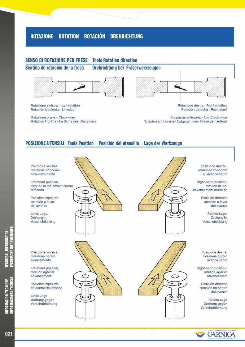
ROTAZIONE ROTATION ROTACION DREHRICHTUNG
SENSO DI ROTAZIONE PER FRESE Tools Rotation direction
Sentido de rotacion de la fresa
Drehrichtung bei Fraserwerkzeugen
I
Rotazione sinistra - Left rotationRotacion izquierda - Linkslauf
Rotazione oraria - Clock wiseRotacion Horaria - Im Sinne des Uhrzeigers
Posizione sinistra,rotazione concordeall'avanzamento
Left-hand position,rotation in the advancementdirection
Posicion izquierdarotacion a favordel avance
Links-Lage,Drehung inVorschubrichtung
Posizione sinistra,rotazione controavanzamento
Left-hand position,rotation againstadvancement
Posicion izquierdaen contra del avance
Links-LageDrehung gegenVorschubrichtung
POSIZIONE UTENSILI Tools Position Posicion del utensilio Lage der Werkzeuge
Rotazione destra - Right rotationRotacion derecha - Rechtslauf
Rotazione antioraria - Anti Clock wiseRotacion antihoraria - Entgegen dem Uhrzeiger laufend
Posizione destra,rotazione concorde
all'avanzamento
Right-hand position,rotation in the
advancement direction
Posicion derecharotacion a favor
delavance
Rechts-Lage,Drehung in
Vorschubrichtung
Posizione destra,rotazione contro
avanzamento
Right-hand position,rotation againstadvancement
Posicion derecharotacion en contra
delavance
Rechts-LageDrehung gegen
Vorschubrichtung
~/ G°"CA

SENSO DI ROTAZIONE PER PANTOGRAFI Router Cutter Rotation DirectionSentido de rotacion para pantografo
Drehrichtung bei Schaftwerkzeugen
Rotazione sinistraLeft rotationRotacion izquierdaLinke Drehrichtung
Rotazione sinistraelica spingente
Left hand rotationDown cut
Rotacion izquierdaHelice contraria
Linke DrehrichtungSpanauswurf nach unten
Rotazione sinistraelica traente
Left hand rotationUp cut
Rotacion izquierdaHelice a favor
Linke DrehrichtungSpanauswurf nach oben
Rotazione destraRight rotation
Rotacion derechaRechte Drehrichtung
Rotazione destraelica traente
Right hand rotationUp cut
Rotacion derechaHelice a favor
Rechte DrehrichtungSpanauswurf nach oben
Rotazione destraelica spingente
Right hand rotationDown cut
Rotacion derechaHelice contraria
Rechte DrehrichtungSpanauswurf nach unten
8%/ (ARNICA
zWsoe oa•
• xe Wzz -- Wr SC VV Mz z•
SW lW WH F
caW R..7SC.2 zM asu. WW ~~ Wz z0 0N VC C•
ee•
0LL. LL.E z
022


