75
4000 Series Panels for Eclipse Installation Guide Rev 5 June 2009

4000 Series Panelsfor
EclipseInstallation Guide
Rev 5June 2009


4000 Series Panels for Eclipse
Thank you for purchasing this product; we hope it will provide many years of reliable and rewarding service.
We would be pleased to hear from you if you have any difficulties, comments or suggestions related to this product, the user documentation or the support service which we offer. Please feel free to contact
us by e-mail, postal mail or telephone.
Please also visit our website whic is continually being enhanced to offer increased levels of information. You can find us at http://www.clearcom.com/
Vitec Group Communications Limited7400 Beach Drive
IQ CambridgeCambridgeshireUnited Kingdom
CB25 9TP
Vitec Group Communications, LLC.850 Marina Village Parkway
AlamedaCA 94501
USA
The Vitec Group plcBeijing Representative Office
Room 706, Tower B Derun Building, YongAn Dongli A No.3
Jianwai Ave., Chaoyang DistrictBeijing, P.R.China 100022
4000 Series Panels for Eclipse Rev 5 Installation GuideSTA0530Z Page i

Installation Guide Rev 5 4000 Series Panels for EclipsePage ii STA0530Z

Policy StatementVitec Group Communications has a policy of continuous improvement of both products anddocumentation and reserves the right modify product specifications and characteristics without notice,at any time.
Vitec Group Communications has endeavoured to ensure that information, details and descriptions setout in this document are correct at the time of publication. Where alterations have been made to theproduct, we will endeavour to produce appropriate additional information such as supplementarydocuments, changes to the website or re-issued copies of a CDROM.
Vitec Group Communications is, however, unable to guarantee that no changes have taken place to thespecification or characteristics of this product after the publication of this document. Vitec GroupCommunications shall not be liable for any loss or damage whatsoever arising from the use of anyinformation, errors or omissions in this document or any use of the product.
Vitec Group Communications declares that the electronic equipment has been manufactured inconformity with the following standards:
Trademarks
MS-DOS and Windows are registered trademarks of Microsoft Corporation.
Ethernet is a registered trademark of Xerox Corporation.
® Clear-Com, CellCom/FreeSpeak and the Clear-Com Communication Systems logo are registeredtrademarks of The Vitec Group plc.
© 2007, 2009 All rights reserved. Neither the whole, nor any part of the information contained herein,nor in the products described in this guide, may be adapted or reproduced in any material form exceptwith the prior written approval of Vitec Group Communications.
European Union Declaration of Conformity
BS EN 50081-1:1992 Electromagnetic compatibility. Generic emission standard.Residential, commercial and light industry.
BS EN 50082-1:1998 Electromagnetic compatibility. Generic immunity standard.Residential, commercial and light industry.
BS EN 60950:1992 Safety of information technology equipment.
4000 Series Panels for Eclipse Rev 5 Installation GuideSTA0530Z Page iii

Installation Guide Rev 5 4000 Series Panels for EclipsePage iv STA0530Z

Revision History
Issue Date Notes
1.0 November 2005 Initial draft issue
1.1 June 2006 Revised and updated
1.2 May 2007 Updated with 4203 and 4206 for ECS 4.1
1.3 May 2008 Add PDE4536 digital interface card for PD4222E
Rev 5 June 2009 Update PDE4537 interface card information
4000 Series Panels for Eclipse Rev 5 Installation GuideSTA0530Z Page v

Installation Guide Rev 5 4000 Series Panels for EclipsePage vi STA0530Z

Warnings and Cautions
Where appropriate, warnings and cautions appear in the text with the following meanings:
WARNING. Given where carrying out an instruction can cause risk of injury or death.
CAUTION. Given where carrying out an instruction can cause risk of damage to the equipment.
WARNING - EARTHING OF EQUIPMENTThis equipment must be properly earthed.
The mains plug must be connected in accordance with the following code:
• BLUE - Neutral (N)• BROWN - Live (L)• GREEN/YELLOW - Earth (E)
As the colours of the wires in the mains lead of this equipment may not correspond with the colouredmarkings identifying the terminals in your plug, proceed as follows:
• The wire which is coloured BLUE must be connected to the terminal which is marked with the let-ter N or is BLACK.• The write which is coloured BROWN must be connected to the terminal which is marked with the letter L or is RED.• The wire which is coloured GREEN and YELLOW must be connected to the terminal which is marked with the letter E or the symbol
CAUTION - ELECTROSTATIC PROTECTION
When carrying out any maintenance or repair taks on this equipment all personnel should ensure thatappropriate grounding equipment is used and checked before commencing work on the equipment.Electrostatic sensitive devices are marked with the symbol
GENERAL WARNINGElectrical shock can cause severe personal injury or death. All major units ofthis equipment are powered by mains voltage. Unless specifically advisedotherwise, DISCONNECT mains supply before carrying out any maintenanceor repair tasks.
This equipment contains electrostatic sensitive devices. Observeprecautions for handling electrostatic sensitive devices when carrying outany maintenance or repair tasks.
4000 Series Panels for Eclipse Rev 5 Installation GuideSTA0530Z Page vii

Installation Guide Rev 5 4000 Series Panels for EclipsePage viii STA0530Z

Glossary of TermsADC Analogue to Digital Converter
ADM Assignment, Diagnostics and Monitoring
BNC Standard co-axial video connector
CAT5 Cable standard for high speed data communica-tions (e.g. 100Base-TX)
CODEC Coder/Decoder
CSU Central Switching Unit
DAC Digital to Analogue Converter
DAK Direct Access Key
dB Decibel
DPDT Double-Pole-Double-Throw
ECS Eclipse Configuration System
EPROM Erasable Programmable Read-Only Memory
FLASH RAM Low voltage electrically erasable and program-mable read-only memory.
GPI General Purpose Interface
GPSF General Purpose Special Function
Howlround Distorted audio - due to feedback of original sig-nal in close proximity.
I/O Input / Output
I/P Input
IFB Interruptible Foldback
Local Programming Modifying the DAK assignments via the Intelli-gent Control Panel SOFT Mode
LCD Liquid Crystal Display
LED Light Emitting Diode
Listen Route An audio route to the Control Panel from a source. The audio is normally heard on the Con-trol Panel's Loudspeaker or Headset.
LS Loudspeaker
Mb Megabyte
MHz Megahertz
N/C Normally Closed
N/O Normally Open
4000 Series Panels for Eclipse Rev 5 Installation GuideSTA0530Z Page ix

NID Non Intrusive Download
NVRAM Non-Volatile Random Access Memory
O/P Output
PCB Printed Circuit Board
Pot. Potentiometer
PSU Power Supply Unit
RAM Random Access Memory
RCU Rear Connector Unit
RJ45 Standard connector for data communications (used with CAT5 cabling for comms. between the matrix and control panels)
RMS Root Mean Square
RU Standard Rack Unit (19 inches wide x 1.75 inches high or 482.6mm x 44.45mm)
Side Tone Side tone is the audio, which is heard in the Headset's earpiece, which is generated by the headset microphone. This allows the operators to hear themselves when using headsets.
SPDT Single-Pole-Double-Throw (switch / relay action)
SPST Single-Pole-Single-Throw (switch / relay action)
TA Terminal Adaptor
Talkback A Broadcast term referring to intercom systems in which 4-wire comms. are used.
Talk Route An audio route from the Control Panel to another destination. The audio is normally generated from the Control Panel's main microphone or Headset microphone.
TBU Telephone Balance Unit
VOX Voice Operated Switch
XLR Audio industry standard connector
Installation Guide Rev 5 4000 Series Panels for EclipsePage x STA0530Z

Consult the named Vitec Group Communications document for further details.
Contact Vitec Group Communications for suitable options.
Tips given.
4000 Series Panels for Eclipse Rev 5 Installation GuideSTA0530Z Page xi

Contents
1 CONTROL PANEL DESCRIPTION .....................................................................11.1 Overview .................................................................................................................. 11.2 Standard Control Panels .......................................................................................... 1
1.2.1 4215E - 16 Key Control Panel (1RU) ............................................................................. 11.2.1.1 4215E (revised) Front View .................................................................................... 21.2.1.2 4215E Front View ................................................................................................... 21.2.1.3 4215E Rear View.................................................................................................... 3
1.2.2 4212E LCD Key and Rotary Encoder Panel .................................................................. 41.2.2.1 4212E (revised) Front View .................................................................................... 41.2.2.2 4212E Front View ................................................................................................... 51.2.2.3 4212E Rear View.................................................................................................... 5
1.2.3 4224E - Intelligent Control Panel (2RU) ........................................................................ 61.2.3.1 4224E (revised) Front View .................................................................................... 61.2.3.2 4224E Front View ................................................................................................... 71.2.3.3 4224E Rear View.................................................................................................... 8
1.2.4 4226E - 32 Key Control Panel (2RU) ........................................................................... 101.2.4.1 4226E Front View ................................................................................................. 101.2.4.2 4226E Rear View.................................................................................................. 11
1.2.5 4222E - LCD Key and Rotary Encoder Panel (2RU) ................................................... 121.2.5.1 4222E Front View ................................................................................................. 121.2.5.2 4222E Rear View.................................................................................................. 13
1.2.6 4222SE - Supervisor Panel ......................................................................................... 141.2.6.1 4222SE Front View............................................................................................... 14
1.2.7 4222SE Rear View ...................................................................................................... 151.2.8 4294E - Desktop Control Panel ................................................................................... 16
1.2.8.1 4294E Front View ................................................................................................. 161.2.8.2 4294E Rear View.................................................................................................. 17
2 Extension Panels ...............................................................................................182.1 4230E Half Width LCD Extension Panel (1RU) ..................................................... 182.2 PD4203E - Level Control Panel (1RU) .................................................................. 20
2.2.1 PD4203E Front View ................................................................................................... 202.2.2 PD4203E Rear View .................................................................................................... 212.2.3 Programming/Configuration ......................................................................................... 21
2.3 PD4206E - 16 Key Extension Panel (1RU) ............................................................ 222.3.1 PD4206E Front View ................................................................................................... 222.3.2 PD4206E Rear View .................................................................................................... 222.3.3 Programming/Configuration ......................................................................................... 23
3 CUSTOM CONTROL PANELS ..........................................................................243.1 4216E - Custom Panel Interface (1RU) ................................................................. 24
3.1.1 4216E Front View ........................................................................................................ 243.1.2 4216E Rear View ......................................................................................................... 243.1.3 Operation ..................................................................................................................... 243.1.4 Installation Information ................................................................................................. 25
3.2 Fitting the Eclipse Isolation Card ........................................................................... 263.3 PDE4536B Digital Options Card ............................................................................ 27
3.3.1 Extension Connector ................................................................................................... 313.4 PDE4537 Options Card ......................................................................................... 31
3.4.1 Control Panel Adjustments .......................................................................................... 323.4.2 PDE4537 Control Interface .......................................................................................... 32
Installation Guide Rev 5 4000 Series Panels for EclipsePage i STA0530Z

3.4.3 PDE4537 Audio Interface ............................................................................................ 333.4.4 I2C Serial Interface Connector .................................................................................... 343.4.5 DC Power Adaptor Connector ..................................................................................... 353.4.6 DC Power Adaptor Ratings .......................................................................................... 35
4 COMMISSIONING .............................................................................................364.1 Control Panels ....................................................................................................... 36
4.1.1 Mains Supply ............................................................................................................... 364.1.2 Applying Power ............................................................................................................ 36
4.2 Normal Operation ................................................................................................... 384.2.1 Functional Checks ....................................................................................................... 384.2.2 Hardware Configuration ............................................................................................... 38
5 SYSTEM PROGRAMMING ...............................................................................396 CABLING ...........................................................................................................40
6.1 Mains Wiring .......................................................................................................... 406.2 Control Panel Wiring .............................................................................................. 40
6.2.1 Solid conductor Co-ax cable ........................................................................................ 406.2.2 RJ45-Terminated Cabling ............................................................................................ 41
6.2.2.1 One-to-One (No Crossover) ................................................................................. 417 Eclipse Manuals ...................................................................................................5
7.1 Software Manuals .................................................................................................... 57.2 Hardware Manuals ................................................................................................... 5
8 TECHNICAL SUPPORT POLICY ........................................................................ v9 RETURN MATERIAL AUTHORIZATION POLICY ............................................. vi10 REPAIR POLICY .............................................................................................viii
4000 Series Panels for Eclipse Rev 5 Installation GuideSTA0530Z Page ii

Installation Guide Rev 5 4000 Series Panels for EclipsePage i STA0530Z
Table of Figures
Figure 1 - 4215E (revised) Front View .................................................................................... 2Figure 2 - 4215E Front View ................................................................................................... 2Figure 3 - 4215E Rear View .................................................................................................... 3Figure 4 - 4212E (revised) Front View .................................................................................... 4Figure 5 - 4212E Front View ................................................................................................... 5Figure 6 - 4212E Rear View .................................................................................................... 5Figure 7 - 4224E (revised) Front View .................................................................................... 6Figure 8 - 4224E Front View ................................................................................................... 7Figure 9 - 4224E Rear View .................................................................................................... 8Figure 10 - 4226E Front View ............................................................................................... 10Figure 11 - 4226E Rear View ................................................................................................ 11Figure 12 4222E Front View .................................................................................................. 12Figure 13 4222E Rear View .................................................................................................. 13Figure 14 4222SE Front View ............................................................................................... 14Figure 15 4222SE Rear View ................................................................................................ 15Figure 16 4294E Front View .................................................................................................. 16Figure 17 4294E Rear View .................................................................................................. 17Figure 18 4230E Front View .................................................................................................. 18Figure 19 4230E Rear View .................................................................................................. 18Figure 20 4230E/4230VE PCB .............................................................................................. 19Figure 21 PD4203E Front View ............................................................................................. 20Figure 22 PD4203E Rear View ............................................................................................. 21Figure 23 PD4203E CConfiguration Switches ...................................................................... 21Figure 24 PD4206E Front View ............................................................................................. 22Figure 25 PD4206E Rear View ............................................................................................. 23Figure 26 PD4206E Configuration Switches ......................................................................... 23Figure 27 4216E Front View .................................................................................................. 24Figure 28 4216E Rear View .................................................................................................. 24Figure 29 Step 1 IC Removal ................................................................................................ 26Figure 30 Step 2 - IC Removed ............................................................................................. 26Figure 31 Top View of Isolation Card .................................................................................... 27Figure 32 View of the Connection to IC Socket ..................................................................... 27Figure 33 PDE4536B Card Without Stereo Jumper .............................................................. 28Figure 34 PDE4536B Card With Stereo Jumper ................................................................... 28Figure 35 PD4222E Before Removing Jumpers ................................................................... 29Figure 36 PD4222E After Removing Jumpers ...................................................................... 29Figure 37 PD4222E with PDE4536B Fitted ........................................................................... 30Figure 38 PD4537 Extension Connector ............................................................................... 31Figure 39 PDE4537 Option Card Fitted to 4000E Panel ....................................................... 32Figure 40 PDE4537 Control Interface Connector .................................................................. 32Figure 41 PDE4537 Audio Interface Connector .................................................................... 33Figure 42 PDE4537 Serial Interface Connector (4216E Custom panel only) ....................... 34Figure 43 PD4537 Power Connector .................................................................................... 35Figure 44 - Panel Installation ................................................................................................. 37Figure 45 - Matrix Startup ...................................................................................................... 38Figure 46 - Coaxial Cable Wiring .......................................................................................... 40

4000 Series Panels for Eclipse Rev 5 Installation GuideSTA0530Z Page i
List of TablesTable 1: ................................................................................................................................ 17Table 2: 4230 Rear Connectors ............................................................................................ 19Table 3: 4230E DIP Switch Settings ..................................................................................... 19Table 4: ................................................................................................................................ 21Table 5: 4203E DAK Mapping............................................................................................... 21Table 6: ................................................................................................................................ 22Table 7: PD4206E DAK Mapping.......................................................................................... 23Table 8: ................................................................................................................................ 24Table 9: ................................................................................................................................ 30Table 9: ................................................................................................................................ 30Table 9: Pin Number ............................................................................................................. 30Table 9: Wire Color ............................................................................................................... 30Table 9: Function................................................................................................................... 30Table 10: RJ-45 Cable Pinout ............................................................................................... 30Table 11: PDE4536 BNC Cable Pinout................................................................................. 31Table 12: PDE4537 Control I/O Pins..................................................................................... 32Table 13: PDE4537 Audio Interface Pins.............................................................................. 34Table 14: .............................................................................................................................. 35Table 15: Co-axial Cable Types............................................................................................ 41Table 16: CAT5 One-to-one Pin-Outs ................................................................................... 41

1 CONTROL PANEL DESCRIPTION
1.1 OverviewThe 4000 Series Control Panels for Eclipse comprise of a range of 1RU and 2RU by 19 inch rack mountunits and a desktop panel.
The standard connection of these panels is via CAT5 (RJ45) cabling to connect analogue audio andRS422 data from the Control Panel to the Matrix.
Other connection methods are possible using twisted pair cable or a bi-directional digital link using75ohm coaxial cable.
When 4000 Series panels are used with Eclipse matrices they must be fitted with a 710684Zisolation unit (19 inch rack panels) or a 710685Z isolation unit (PD4294 desktop panels).Note: The 710684Z isolation unit was previously called a PD45103.There are also Extension Panels that are used to increase the number of buttons per panel or to addlevel control facilities. These Extension Panels connect to the main Control Panel via screened ribboncable. A Custom Panel Interface is also available to remotely connect keys and displays from the mainControl Panel, so that a custom panel can be made to fit various size and shape constraints.
Note: If at any time a panel is removed from the system with its keys still active, the relevantmatrix crosspoints will remain in force until the panel is reconnected. Because of this fact, apanel should only be removed after all of its keys have been de-selected.Panels are DC powered by the 150/UNI and 151/UNI DIN 4 universal 110-240V mains adaptors.
1.2 Standard Control Panels
1.2.1 4215E - 16 Key Control Panel (1RU)The PD4215E - 16 Key Control Panel Level Control Panel has the following features:
• 16 centrally programmed pushbuttons, including reply
• Programmable pushbuttons for talk, listen, talk & listen, talk & forced listen and dual talk & listen functions
• Connection for 20 Key Extension and Level Control Panels including power
• Separate audio signals to Main and Aux level controls
• DC powered
• Audio and control interface options card including GPI's
• Full signalisation of send and receive routes
• Plug-in microphone or headset operation
• Microphone gain, headset gain and side-tone are software configurable
• Headset connector with pushbutton select
Installation Guide Rev 5 4000 Series Panels for EclipsePage 1 STA0530Z

1.2.1.1 4215E (revised) Front View
Figure 1 - 4215E (revised) Front View
1.2.1.2 4215E Front View
Figure 2 - 4215E Front View
1 Microphone Socket 7 Direct Access Key (DAK)2 Microphone Mute Pushbutton and LED 8 DAK Indicator LED3 Designation Strip 9 Headset Select Pushbutton and LED4 Loudspeaker Aperture 10 Headset Socket5 Auxiliary Volume Control and LED 11 Reply Key6 Volume Control and LED
1 Microphone Socket 7 Direct Access Key (DAK)
4000 Series Panels for Eclipse Rev 5 Installation GuideSTA0530Z Page 2

1.2.1.3 4215E Rear View
Figure 3 - 4215E Rear View
2 Microphone Mute Pushbutton and LED 8 DAK Indicator LED3 Designation Strip 9 Headset Select Pushbutton and LED4 Loudspeaker Aperture 10 Headset Socket5 Auxiliary Volume Control and LED 11 Reply Key6 Volume Control and LED
1 Earth Connection 5 Eclipse Matrix Comms Connector (RJ45)2 DC Power Connector (DIN) 6 Extension Panel Connector3 Control I/O (Optional) 7 Matrix Comms Connector (not used)4 Audio I/O (Optional)
2 3 4 5 6 71
Installation Guide Rev 5 4000 Series Panels for EclipsePage 3 STA0530Z
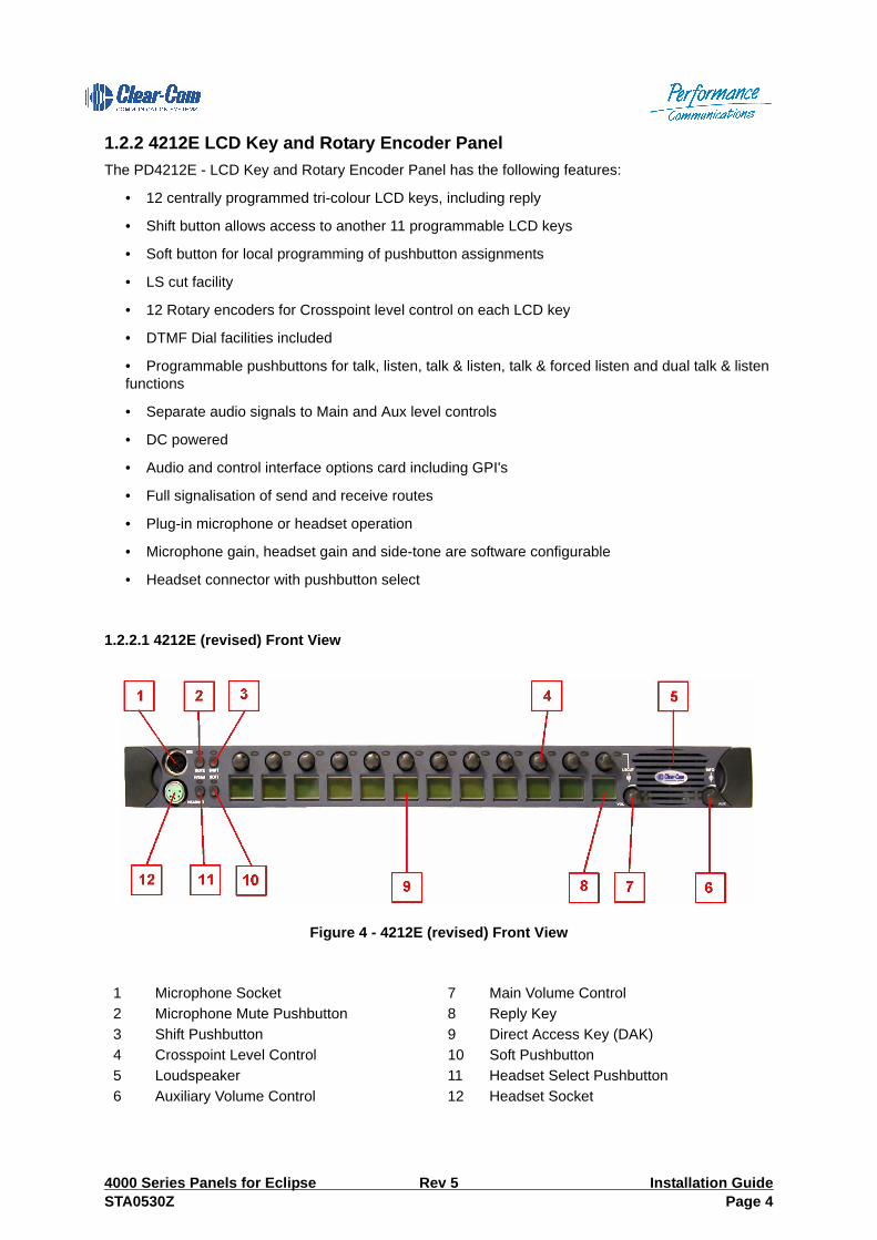
1.2.2 4212E LCD Key and Rotary Encoder PanelThe PD4212E - LCD Key and Rotary Encoder Panel has the following features:
• 12 centrally programmed tri-colour LCD keys, including reply
• Shift button allows access to another 11 programmable LCD keys
• Soft button for local programming of pushbutton assignments
• LS cut facility
• 12 Rotary encoders for Crosspoint level control on each LCD key
• DTMF Dial facilities included
• Programmable pushbuttons for talk, listen, talk & listen, talk & forced listen and dual talk & listen functions
• Separate audio signals to Main and Aux level controls
• DC powered
• Audio and control interface options card including GPI's
• Full signalisation of send and receive routes
• Plug-in microphone or headset operation
• Microphone gain, headset gain and side-tone are software configurable
• Headset connector with pushbutton select
1.2.2.1 4212E (revised) Front View
Figure 4 - 4212E (revised) Front View
1 Microphone Socket 7 Main Volume Control2 Microphone Mute Pushbutton 8 Reply Key3 Shift Pushbutton 9 Direct Access Key (DAK)4 Crosspoint Level Control 10 Soft Pushbutton5 Loudspeaker 11 Headset Select Pushbutton6 Auxiliary Volume Control 12 Headset Socket
4000 Series Panels for Eclipse Rev 5 Installation GuideSTA0530Z Page 4

1.2.2.2 4212E Front View
Figure 5 - 4212E Front View
NOTE: Microphone is shown here for illustrative purposes only. Contact Vitec Group Communicationsfor details of suitable products.
1.2.2.3 4212E Rear View
Figure 6 - 4212E Rear View
1 Microphone Socket 7 Main Volume Control2 Microphone Mute Pushbutton 8 Reply Key3 Shift Pushbutton 9 Direct Access Key (DAK)4 Crosspoint Level Control 10 Soft Pushbutton5 Loudspeaker 11 Headset Select Pushbutton6 Auxiliary Volume Control 12 Headset Socket
1 Earth Connection 5 Eclipse Matrix Comms Connector (RJ45)2 DC Power Connector (DIN) 6 Extension Panel Connector3 Control I/O (Optional) 7 Matrix Comms Connector (not used)4 Audio I/O (Optional)
2 3 4 5 6 71
Installation Guide Rev 5 4000 Series Panels for EclipsePage 5 STA0530Z

1.2.3 4224E - Intelligent Control Panel (2RU)The PD4224E - Intelligent Control Panel has the following features :
• 32 programmable pushbuttons, including reply, locally and centrally programmable • Dual row alphanumeric displays (4 or 8 character choice)• Shift button allows access to another 32 programmable pushbuttons• Soft button for local programming of pushbutton assignments• LS cut facility• Rotary encoder for crosspoint level control • DTMF Dial facilities with electronic dial-pad included• Programmable pushbuttons for talk, listen, talk & listen, talk & forced listen and dual talk & listen functions• Connection for 20 Key Extension and Level Control Panels including power• Separate audio signals to Main and Aux level controls• DC powered• Audio and control interface options card including GPI's• Full signalisation of send and receive routes• Plug-in microphone or headset operation• Microphone gain, headset gain and side-tone are software configurable• Headset connector with pushbutton select
1.2.3.1 4224E (revised) Front View
Figure 7 - 4224E (revised) Front View
1 Microphone Socket 11 Main Volume Control and Associated LED2 Direct Access Key (DAK) 12 Reply Key3 Indicator LED 13 Call Reject Pushbutton and Associated
LED4 Shift Pushbutton and Associated LED 14 Soft Pushbutton and Associated LED5 Info Pushbuttonand Associated LED 15 Vacuum Fluorescent Display (VFD)
4000 Series Panels for Eclipse Rev 5 Installation GuideSTA0530Z Page 6

NOTE: Microphone is shown here for illustrative purposes only.
1.2.3.2 4224E Front View
Figure 8 - 4224E Front View
NOTE: Microphone is shown here for illustrative purposes only. Contact Vitec Group Communicationsfor details of suitable products.
6 Loudspeaker Aperture 16 Headset Socket7 Crosspoint Level Control 17 Headset Select Pushbutton and Associ-
ated LED8 Rack Mounting Screws (with cover
removed)18 Cover Over Rack Mounting Points
9 Auxiliary Volume Control and Associated LED
19 Microphone Mute and Associated LED
10 Loudspeaker Cut Pushbutton and Associ-ated LED
1 Microphone Socket 11 Main Volume Control and Associated LED2 Direct Access Key (DAK) 12 Reply Key3 Indicator LED 13 Call Reject Pushbutton and Associated
LED4 Shift Pushbutton and Associated LED 14 Soft Pushbutton and Associated LED5 Info Pushbuttonand Associated LED 15 Vacuum Fluorescent Display (VFD)6 Loudspeaker Aperture 16 Headset Socket7 Crosspoint Level Control 17 Headset Select Pushbutton and Associ-
ated LED8 Rack Mounting Screws (cover removed) 18 Cover Over Rack Mounting Points9 Auxiliary Volume Control and Associated
LED19 Microphone Mute and Associated LED
10 Loudspeaker Cut Pushbutton and Associ-ated LED
Installation Guide Rev 5 4000 Series Panels for EclipsePage 7 STA0530Z

1.2.3.3 4224E Rear View
Figure 9 - 4224E Rear View
1 Earth Connection 5 Eclipse Matrix Comms Connector (RJ45)2 DC Power Connector (DIN) 6 Extension Panel Connector3 Control I/O (Optional) 7 Matrix Comms Connector (not used)4 Audio I/O (Optional)
2 3 4 5 6 71
4000 Series Panels for Eclipse Rev 5 Installation GuideSTA0530Z Page 8

Installation Guide Rev 5 4000 Series Panels for EclipsePage 9 STA0530Z

1.2.4 4226E - 32 Key Control Panel (2RU)The PD4226E -Control Panel has the following features:
• 32 programmable pushbuttons, including reply, locally and centrally programmable
• LS cut facility
• Programmable pushbuttons for talk, listen, talk & listen, talk & forced listen and dual talk & listen functions
• Connection for 20 Key Extension and Level Control Panels including power
• Separate audio signals to Main and Aux level controls
• DC powered
• Audio and control interface options card including GPI's
• Full signalisation of send and receive routes
• Plug-in microphone or headset operation
• Microphone gain, headset gain and side-tone are software configurable
• Headset connector with pushbutton select
1.2.4.1 4226E Front View
Figure 10 - 4226E Front View
1 Microphone Socket 7 Loudspeaker Cut Pushbutton2 Indicator LED 8 Main Volume Control and Associated LED3 Direct Access Key (DAK) 9 Reply Key4 Designation Strips 10 Headset Socket5 Loudspeaker Aperture 11 Headset Select Button and Associated
LED6 Auxiliary Volume Control and LED 12 Microphone Mute and Associated LED
4000 Series Panels for Eclipse Rev 5 Installation GuideSTA0530Z Page 10
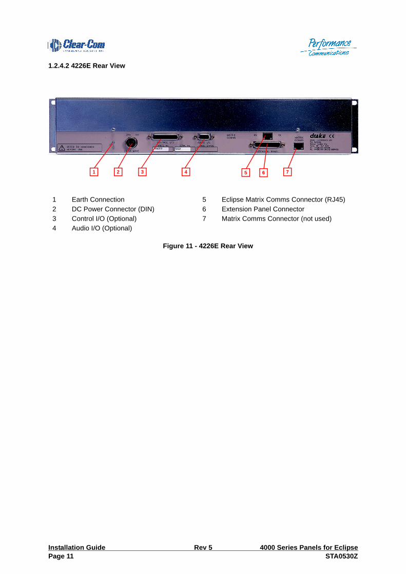
1.2.4.2 4226E Rear View
Figure 11 - 4226E Rear View
1 Earth Connection 5 Eclipse Matrix Comms Connector (RJ45)2 DC Power Connector (DIN) 6 Extension Panel Connector3 Control I/O (Optional) 7 Matrix Comms Connector (not used)4 Audio I/O (Optional)
2 3 4 5 6 71
Installation Guide Rev 5 4000 Series Panels for EclipsePage 11 STA0530Z

1.2.5 4222E - LCD Key and Rotary Encoder Panel (2RU)The PD4222E - LCD Key Panel and Rotary Encoder Panel has the following features:
• 24 centrally programmed tri-colour LCD keys, including reply
• Shift button allows access to another 23 programmable LCD keys
• Soft button for local programming of pushbutton assignments
• LS cut facility
• 24 rotary encoders for Crosspoint level control of each LCD key
• DTMF Dial facilities included
• Programmable pushbuttons for talk, listen, talk & listen, talk & forced listen and dual talk & listen functions
• Separate audio signals to Main and Aux level controls
• DC powered
• Audio and control interface options card including GPI's
• Full signalisation of send and receive routes
• Plug-in microphone or headset operation
• Microphone gain, headset gain and side-tone are software configurable
• Headset connector with pushbutton select
1.2.5.1 4222E Front View
Figure 12 4222E Front View
1 Microphone Socket 8 Main Volume Control2 Microphone Mute Pushbutton 9 Reply Key3 Shift Pushbutton 10 Direct Access Key (DAK)4 Crosspoint Level Control 11 Soft Pushbutton5 Loudspeaker 12 Headset Select Pushbutton6 Auxiliary Volume Control 13 Headset Socket7 Loudspeaker Cut Pushbutton
4000 Series Panels for Eclipse Rev 5 Installation GuideSTA0530Z Page 12

Note:•Microphone is shown here for illustrative purposes only. Contact Vitec GroupCommunications for details of suitable products.
1.2.5.2 4222E Rear View
Figure 13 4222E Rear View
1 Earth Connection 5 Eclipse Matrix Comms Connector (RJ45)2 DC Power Connector (DIN) 6 Extension Panel Connector3 Control I/O (Optional) 7 Matrix Comms Connector (not used)4 Audio I/O (Optional)
2 3 4 5 6 71
Installation Guide Rev 5 4000 Series Panels for EclipsePage 13 STA0530Z

1.2.6 4222SE - Supervisor PanelThe 4222SE Supervisor Panel has the same features as a standard 4222 LCD Key Panel, plus thefollowing additions:
• Mimics and controls any target panel in the local system (including crosspoint levels and configu-ration data)
• Target panels must be 4222E and 4212E LCD Key Panels
• Up to 8 Supervisor Panels supported in a system
1.2.6.1 4222SE Front View
Figure 14 4222SE Front View
1 Microphone Socket 8 Main Volume Control2 Microphone Mute Pushbutton 9 Reply Key3 Shift Pushbutton 10 Direct Access Key (DAK)4 Level Control 11 Soft Pushbutton5 Loudspeaker 12 Headset Select Pushbutton6 Auxiliary Volume Control 13 Headset Socket7 Loudspeaker Cut Pushbutton
4000 Series Panels for Eclipse Rev 5 Installation GuideSTA0530Z Page 14

1.2.7 4222SE Rear View
Figure 15 4222SE Rear View
1 Earth Connection 5 Eclipse Matrix Comms Connector (RJ45)2 DC Power Connector (DIN) 6 Extension Panel Connector3 Control I/O (Optional) 7 Matrix Comms Connector (not used)4 Audio I/O (Optional)
2 3 4 5 6 71
Installation Guide Rev 5 4000 Series Panels for EclipsePage 15 STA0530Z

1.2.8 4294E - Desktop Control PanelThe PD4294E - Desktop Control Panel has the following features:
• 16 programmable pushbuttons, including reply, locally and centrally programmable
• Dual row alphanumeric displays (4 or 8 character choice)
• Shift button allows access to another 16 programmable pushbuttons
• Soft button for local programming of pushbutton assignments
• LS cut facility
• Rotary encoder for crosspoint level control
• Programmable pushbuttons for talk, listen, talk & listen, talk & forced listen and dual talk & listen functions
• Loudspeaker output jack
• Separate audio signals to Main and Aux level controls
• DC mains powered (by supplied AC Power Adapter)
• Audio and control interface options card including GPI's
• Full signalisation of send and receive routes
• Plug-in microphone or headset operation
• Microphone gain, headset gain and side-tone adjustment at rear
• Headset connector with pushbutton select
1.2.8.1 4294E Front View
Figure 16 4294E Front View
1 Microphone Socket 11 Loudspeaker 2 Headset Socket 12 Shift Pushbutton3 Direct Access Key (DAK) 13 Info Pushbutton4 Talk Tally LED 14 Soft Pushbutton
4000 Series Panels for Eclipse Rev 5 Installation GuideSTA0530Z Page 16

1.2.8.2 4294E Rear View
Figure 17 4294E Rear View
5 Listen Tally LED 15 Call Reject Pushbutton6 Alphanumeric LCD Display 16 Reply Key7 Headset Select Pushbutton 17 Level Control Pushbutton8 Microphone Mute Pushbutton 18 Loudspeaker Cut Pushbutton9 Main Volume Control 19 Rotary Level Control10 Auxiliary Volume Control 20 Contrast Control
Table 1:
1 DC Connector 3 Matrix Comms Connector (not used)
2 Eclipse Matrix Comms Connector (RJ45)
2 31
Installation Guide Rev 5 4000 Series Panels for EclipsePage 17 STA0530Z

2 Extension Panels
2.1 4230E Half Width LCD Extension Panel (1RU)
Figure 18 4230E Front View
The 4230E panel is available in versions for horizontal and vertical mounting.
Figure 19 4230E Rear View
1 Shift mode LED 5 Reply Key2 Crosspoint Level Control 6 Direct Access Key (DAK)3 Talk Tally LED 7 Shift Pushbutton4 Listen Tally LED
4000 Series Panels for Eclipse Rev 5 Installation GuideSTA0530Z Page 18

The 4230E contains an internal DIP switch which is used to determine the panel mode.
Figure 20 4230E/4230VE PCBThe DIP switch settings are given in the table below.
Table 2: 4230 Rear Connectors
1 Connection for further 4230E Extension panel
2 Connection to control panel or 4230E extension panel
3 DC power connector (DIN)
Table 3: 4230E DIP Switch Settings
SW 1 SW 2 SW 3 SW 4 Function
OFF OFF OFF OFF Legacy mode
ON OFF OFF OFF Self Test
OFF ON OFF OFF Dumb Panel Mode
OFF ON OFF ON Vertical Mode
Installation Guide Rev 5 4000 Series Panels for EclipsePage 19 STA0530Z

2.2 PD4203E - Level Control Panel (1RU)The 4203 - Level Control Panel has the following features:
• 20 programmable crosspoint, group, IFB or conference level controls• Connection to 4000 Series II 16 and 32 key control panels• Calibrated levels• Internal adjustments for gain (+18dB to -65dB)• Designation strips for use with non-display panels
The Extension panel is plugged via a 25-way D-type connector to the EXTENSION PANEL connector atthe rear of the associated Control Panel. Switch off the power before connecting or disconnecting thepanel.
The maximum cable length between a 4000 Series II Control Panel and the Level Control Panel is 1.5metres.
Note: The 4203E Extension Panel cannot be connected to any the range of LCD key panels or thePD4217 control panel.
2.2.1 PD4203E Front View
Figure 21 PD4203E Front View
1 Level Adjustment Control 2 Designation Strip
4000 Series Panels for Eclipse Rev 5 Installation GuideSTA0530Z Page 20

2.2.2 PD4203E Rear View
Figure 22 PD4203E Rear View
2.2.3 Programming/ConfigurationA hexadecimal-encoded rotary switch determines the function of each Level Control Panel. This switchgives 16 unique address ranges. Two trimmers VR21 and VR22 adjust the top and bottom values of thegain range as shown below.
Figure 23 PD4203E CConfiguration SwitchesNote: The first and last two level controls are disabled when the Level Control Panel maps to thetop or bottom row 16 DAKs of either the Main or Shift Page of the control panel.
Table 4:
1 Extension Connector
Table 5: 4203E DAK Mapping
SW1 Position Level Control Panel to DAK Mapping
0 Main Page Top row 16 DAKs
1 Main Page bottom row 16 DAKs
2 Extension Panel 1 DAKs or Shift Page Top row 16 DAKs
3 Extension Panel 2 DAKs or Shift Page Bottom row 16 DAKs
4 Extension Panel 3 DAKs
5 Extension Panel 4 DAKs
Installation Guide Rev 5 4000 Series Panels for EclipsePage 21 STA0530Z

2.3 PD4206E - 16 Key Extension Panel (1RU)The 4206 - 16 Key Extension Panel has the following features:
• 16 centrally programmable DAK pushbuttons.• Individual LED signalisation for each key• Connection to 4000 Series II 16 and 32 key Control Panel range• Designation strip for key identification
The Extension panel is plugged via a 25-way D-type connector to the EXTENSION PANEL connector atthe rear of the associated Control Panel. Switch off the power before connecting or disconnecting thepanel.
The maximum cable length between the 4206 and a 4000 Series II Control Panels is 1.5 metres.
Note: The 4206 Extension Panel cannot be connected to any the range of LCD key panels or thePD4217 control panel.
2.3.1 PD4206E Front View
Figure 24 PD4206E Front View
2.3.2 PD4206E Rear View
1 Indicator LED 3 Designation Strip2 Direct Access Key (DAK)
Table 6:
1 Extension Connector
4000 Series Panels for Eclipse Rev 5 Installation GuideSTA0530Z Page 22

Figure 25 PD4206E Rear View
2.3.3 Programming/ConfigurationA hexadecimal-encoded rotary switch on the Extension Panel card sets the panel address for the benefitof the main control panel. The default position for the extension panel when fitted with standard softwareis at position 0.
Figure 26 PD4206E Configuration Switches
Table 7: PD4206E DAK Mapping
Rotary Switch Position Extension DAK Numbers
0 33 to 52
1 53 to 72
2 73 to 92
3 93 to 112
Rotary Switch
Installation Guide Rev 5 4000 Series Panels for EclipsePage 23 STA0530Z

3 CUSTOM CONTROL PANELS
3.1 4216E - Custom Panel Interface (1RU)The 4216E - Custom Panel Interface has the following features:
• Audio facilities include microphone output, level control• Control signals sent to the custom panel through a serial interface• Auxiliary audio and control outputs can be fitted to the interface with the addition of a PDE4537 options card
3.1.1 4216E Front View
Figure 27 4216E Front View
3.1.2 4216E Rear View
Figure 28 4216E Rear View
3.1.3 OperationAt the Custom Panel interface, audio and control signals are separated. Audio facilities such as Micinput, Level control, LS output and Headset input are wired to the Audio (B) Input / Output Connector.Control signals are relayed to the custom control panel through a serial interface from the I2C SerialInterface Connector. DC power is supplied via this link, giving 30VA of lamp drive (e.g. 48 x 28V lamps/LEDs).
Table 8:
1 Extension Connector 4 Eclipse Matrix Comms Connector (RJ45)
2 Control I/O (Optional) 5 Matrix Comms Connector (not used))
3 Power Supply Connector 6 Audio (B) Input/Output Connector
4000 Series Panels for Eclipse Rev 5 Installation GuideSTA0530Z Page 24

The remote custom control panel utilises a number of cascaded PDE3531/P/SL/D cards to make up theports for the required number of switches/lamps/displays.
3.1.4 Installation InformationThe microphone/s and volume pot/s should be wired with good quality 7/0.2 screened cable over amaximum distance of 25m.The control interface can be connected to the remote panel with a cable run of up to 20m using 15-wayscreened cable or 15-way screened ribbon cable.Connection to the matrix is made with coaxial cable, or CAT5 for RS422 serial operation.
Installation Guide Rev 5 4000 Series Panels for EclipsePage 25 STA0530Z

3.2 Fitting the Eclipse Isolation CardAll 4000 series panels (except the PD4203E and PD4206E) used with Eclipse systems should normallybe fitted with an isolation card providing a separate RJ45 socket for connection to the Eclipse matrix.The original matrix connector is no longer used. For 1RU and 2RU rack mount panels the isolation cardpart number is 710684Z while the PD4294 desktop panel used part number 710685Z.The steps required to install an isolation card are shown below.Note:•The isolation cards should only be installed by authorized Vitec Group Communicationsengineers.
1. Remove the cover from the panel.2. Remove the small 8 pin IC from the main board (see below)
Figure 29 Step 1 IC Removal
Figure 30 Step 2 - IC Removed3. Fit the 710684Z isolation card (see below). Note the 4 pin connector on the 710684Z card fits onto
the empty IC socket.
Remove this IC
IC removed
4000 Series Panels for Eclipse Rev 5 Installation GuideSTA0530Z Page 26

Figure 31 Top View of Isolation Card
Figure 32 View of the Connection to IC Socket
4. The rear metalwork may have to be modified for the new RJ45 connector.
5. Replace panel cover.
5.1 PDE4536B Digital Options CardDigital connection via CAT5 or coaxial with a 4000 Series 2 PD4222E panel is made possible by fittingthe PDE4536B options card.
A standard female BNC type connector or RJ-45 connector is used to connect 4000 series II panels toan Eclipse matrix via a Digital interface such as an AES-6 or DIG-2.
In order to enable stereo on the PD4222E panel a jumper must be fitted to the PDE4536B card and twojumpers must be removed on the main PD4222E panel.
Installation Guide Rev 5 4000 Series Panels for EclipsePage 27 STA0530Z
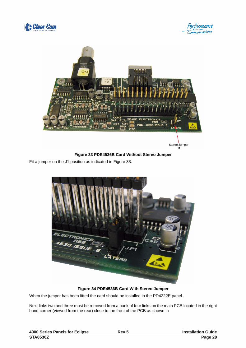
Figure 33 PDE4536B Card Without Stereo JumperFit a jumper on the J1 position as indicated in Figure 33.
Figure 34 PDE4536B Card With Stereo JumperWhen the jumper has been fitted the card should be installed in the PD4222E panel.
Next links two and three must be removed from a bank of four links on the main PCB located in the righthand corner (viewed from the rear) close to the front of the PCB as shown in
4000 Series Panels for Eclipse Rev 5 Installation GuideSTA0530Z Page 28

Figure 35 PD4222E Before Removing JumpersRemove the two middle jumpers (links 2 and 3) as shown in Figure 36.
Figure 36 PD4222E After Removing JumpersThe PDE4536B card should be installed in the panel so that the BNC and RJ-45 connectors line up withthe cutouts and pressed down to ensure the pins at the rear of the PDE4536B card are properly seatedin the connector on the main PCB. The spring contact on the end of the BNC must be inside the rear ofthe panel so that it is in contact with the metal (Figure 37).
Installation Guide Rev 5 4000 Series Panels for EclipsePage 29 STA0530Z

Figure 37 PD4222E with PDE4536B FittedTable 9:
Table 10: RJ-45 Cable Pinout
PIN NUMBER WIRE COLOR FUNCTION
1 White/Orange not used
2 Orange not used
3 White/Green Tx (+)
4 Blue Rx (+)
5 White/Blue Rx (-)
6 Green Tx (-)
7 White/Brown not used
8 Brown not used
4000 Series Panels for Eclipse Rev 5 Installation GuideSTA0530Z Page 30

5.1.1 Extension ConnectorThis 25 way D-Type connector allows connection to a 4203E or 4206E panel.
Figure 38 PD4537 Extension ConnectorNote:•Maximum total cable length between a 4000 Series II Control Panel and 4203E or 4206EExtension Panels is 1.5 metres.The Connector on the 4203E and 4206E Level Control and Extension Panels are equipped with a plugrather than a socket.
5.2 PDE4537 Options CardThe Panel Options Card, which can be fitted to any standard 4000 Series Control Panel, providesadditional control and audio interfaces. These allow the panel to be locally customised. The card alsoallows a serial interface to be fitted to the 4216E Custom Interface panel.An example of a PDE4537 options card fitted to a 4000 Series panel is shown in Figure 39.
Table 11: PDE4536 BNC Cable Pinout
Description Pin Reference
Signal Core
Return Screen
Description Pin numberExtack / 1Write / 2Intkey / 3D0 4D2 5D4 6D6 7A0 8A2 9A4 10+5 Volts 11- 12- 13Select / 14Gnd 15Gnd 16D1 17D3 18D5 19D7 20A1 21A3 22A5 23A6 24- 25
Installation Guide Rev 5 4000 Series Panels for EclipsePage 31 STA0530Z

Figure 39 PDE4537 Option Card Fitted to 4000E Panel
5.2.1 Control Panel AdjustmentsMicrophone gain, headset microphone gain and side tone adjustment are software configurable.
5.2.2 PDE4537 Control InterfaceExternal Control Interfaces provide up to four opto-isolated control inputs and two double-polechangeover relays. The first two control inputs are user-defined via the ECS Panel Configuration programming. Theremaining two control inputs (3 and 4) are allocated to specific functions:Input 3: Reply Input. This acts in parallel with the Reply key on the control panels.Input 4: Custom Applications. This input is reserved for custom applications In the case of the 4222SEsupervisor panel input 4 is used to terminate a supervisor (mimic/control) session.A 25-way D-type socket is provided for control inputs and outputs.
Figure 40 PDE4537 Control Interface Connector
Table 12: PDE4537 Control I/O Pins
Description Pin Description Pin
Control I/P 1 +ve 1 Control I/P 1 -ve 14
Control I/P 2 +ve 2 Control I/P 2 -ve 15
Control I/P 3 +ve 3 Control I/P 3 -ve 16
Control I/P 4 +ve 4 Control I/P 4 -ve 17
4000 Series Panels for Eclipse Rev 5 Installation GuideSTA0530Z Page 32

The relay 1 and 2 input/outputs on the PDE4537 control interface connector are referred to in ECS Controls as “Panel AUX relays” and “Panel mute relays”. The relay naming between ECS and the control interface pinout is:
Relay 1 - Panel mute relay
Relay 2 - Panel AUX relay
5.2.3 PDE4537 Audio InterfaceThe audio interface provides two balanced audio inputs and two balanced audio outputs.A 9-way D-type socket is used.
Figure 41 PDE4537 Audio Interface Connector
Relay 1 Common A 6 Relay 1 Common B 19
Relay 1 Normally Closed A 7 Relay 1 Normally Closed B 20
Relay 1 Normally Open A 8 Relay 1 Normally Open B 21
Relay 2 Common A 9 Relay 2 Common B 22
Relay 2 Normally Closed A 10 Relay 2 Normally Closed B 23
Relay 2 Normally Open A 11 Relay 2 Normally Open B 24
+V (unregulated) 12 -V (unregulated) 25
0V 5
0V 18
0V 13
Table 12: PDE4537 Control I/O Pins
Description Pin Description Pin
Installation Guide Rev 5 4000 Series Panels for EclipsePage 33 STA0530Z

Input 1 (MMI, Mix Mix In) is mixed directly into the microphone audio path to the matrix.
Input 2 (AUX, Aux Mix In) is mixed onto the loudspeaker path via the AUX volume control on the controlpanel.
Output 1 (MMS, Mix Mix Send) provides a balanced output of the microphone audio mix.
Output 2 (LSMS, Loudspeaker Mix Send) provides a balanced output of the loudspeaker mix.
5.2.4 I2C Serial Interface ConnectorThis 15-way D-Type connector is only supported on the 4216E Custom Panel Interface and is notsupported on 4000 Series control panels. The connector provides the I2C Serial Interface for connectingto the PDE3531 Custom Panel Cards, for custom applications.
Figure 42 PDE4537 Serial Interface Connector (4216E Custom panel only)
Table 13: PDE4537 Audio Interface Pins
Description Pin
Mic Mix In +ve 1
Mic Mix In -ve 6
Aux In +ve 2
Aux In -ve 7
Mic Mix Out +ve 3
Mic Mix Out -ve 8
Loudspeaker Mix Out +ve 4
Loudspeaker Mix Out -ve 9
0V 5
4000 Series Panels for Eclipse Rev 5 Installation GuideSTA0530Z Page 34

5.2.5 DC Power Adaptor ConnectorThis 4-pin DIN connector is used to connect the Vitec Group Communications-supplied 150/UNI and151/UNI DC Power Adaptors.The pin-out of the 4-pin DIN Power connector is as follows:
Figure 43 PD4537 Power Connector
5.2.6 DC Power Adaptor RatingsThe 150/UNI and 151/UNI DIN power adaptors are supplied for DC panel applications. The followingspecifications apply:150/UNI - 24V, 1.5A151/UNI - 24V, 4.5ANOTE: The 151/UNI adaptor is supplied for the router panel, where a typical application may supportmore than two extension panels.
Table 14:
Contact Vitec Group Communications Sales for details of suitable AC Power Supplies
USE ONLY VITEC GROUP COMMUNICATIONS APPROVED POWER SUP-PLIES.
Installation Guide Rev 5 4000 Series Panels for EclipsePage 35 STA0530Z

6 COMMISSIONING
6.1 Control Panels
6.1.1 Mains SupplySome 4000 Series II control panels have an un-switched IEC inlet located at the rear of each unit. Beforeapplying power, check that the voltage selector is set to the correct supply voltage and that the fusesfitted are of the correct rating for that voltage. See section on fuse details.
6.1.2 Applying PowerOn connection of AC power, with panel-to-matrix cable connected, control panels with LCD display fittedshould show the message sequence shown overleaf.
Following this sequence, the panel display will revert to normal, displaying key assignments asprogrammed in ECS.
Operating system software download is indicated by the count-up display shown.
NOTE: This process can take a few minutes, depending on system size and software version.
Should a download be interrupted while in progress, the panel will wait for 45 seconds before requestinga new download.
During a 'bootstrap' download (e.g. a blue, red and black reset), all panel keys and functions arerendered inoperative.
If the control panel is connected to a different matrix port, the panel is re-configured by the matrix, inorder to update its key allocations and panel location.
In this case, following the last message, a further message will appear, as shown. After a period of a fewseconds the panel will revert to normal operation with its new configuration in place.
WARNINGDo not apply AC power until all installation operations are
complete. Check earth connections before applying power.
4000 Series Panels for Eclipse Rev 5 Installation GuideSTA0530Z Page 36

Figure 44 - Panel Installation
YES
YES
NO
NO
Installation Guide Rev 5 4000 Series Panels for EclipsePage 37 STA0530Z

6.2 Normal OperationAt the end of its self-check routine, each control panel will revert to the normal operating mode, anddisplays and key functions will be restored.
The following messages are displayed when a panel is powered up with no communications to a matrixand if communications are lost once a matrix configuration has been loaded. In addition to this, a"SYSTEM INACTIVE" message appears when the Matrix Processor Card is removed, provided thatcommunications to the matrix were normal prior to removal of the card.
When the processor card is re-inserted, the matrix resets, and the panel will return to its normal DAKdisplay.
Figure 45 - Matrix Startup
6.2.1 Functional ChecksHaving established correct data communications between all control panels and the matrix (indicated bythe illumination of the relevant yellow LEDs on the PDE4606B PCC cards in the matrix frame), simplefunctional checks can now be carried out.
Using Direct Access Keys (DAKs) or the dial-up keypad, make a call to your panel. Check that audio ispresent at your panel. Try another panel and verify the reverse path using the remote panels Reply Key.This will check each panel's audio and control functions.
Check the operation of the headset connection with a test headset.
6.2.2 Hardware ConfigurationOther than software configuration, there are a limited number of user-adjustable controls on the Eclipse4000 Series system. Most rack and panel cards have optional link settings.
Contact Vitec Group Communications Sales Department for further information.
4000 Series Panels for Eclipse Rev 5 Installation GuideSTA0530Z Page 38

7 SYSTEM PROGRAMMINGThis configuration may be edited 'off-line' using the ECS software package supplied with the system. Anew configuration may be downloaded to the Eclipse Series matrix via an RS232 or Ethernet Link (if anEthernet card has been fitted), and will be loaded into the matrix and control panel memories when thesystem is 'reset'.
A non-intrusive download (NID) facility is also available, making it possible in most circumstances todownload a configuration without the need to reset the system. During this process the system will bepartially inoperable for 1-3 seconds, depending on system usage and size.
NOTE: During a non-intrusive download the current audio routing is unaffected; only new pushbuttonoperations are inhibited during this period.
ECS may be used for rapid updates to a system's configuration, and for hardware and software statusmonitoring.
NOTE: If at any time a panel is removed from the system with its keys still active, the relevant matrixcrosspoints will remain in force until the panel is reconnected. Because of this fact, a panel should onlybe removed after all of its keys have been de-selected.
Installation Guide Rev 5 4000 Series Panels for EclipsePage 39 STA0530Z

8 CABLING
8.1 Mains WiringThe cable for mains power should have a minimum of 240V 5A AC carrying capacity and must beterminated in a standard IEC female connector.
8.2 Control Panel Wiring
8.2.1 Solid conductor Co-ax cableEach control panel requires a single cable connection to the Eclipse 4000 Series Matrix using 75 Ohmco-axial cable (see above for details). Lay in these cables as required and terminate both ends in maleBNC connectors as shown.
Note: It is advisable to provide sufficient cable length within the Eclipse 4000 Series equipmentbay to allow connection of cables to any of the panel connectors. This will allow panels to be re-connected in alternative positions if necessary.Each panel cable should be identical with panel 'port' number at both ends. The recommendedtermination procedure is shown.
Figure 46 - Coaxial Cable Wiring
Note: Cable stripping requirements may vary depending on connector manufacturer.Co-axial connecting cable for digital control panels should have an outside diameter suitable for theintended BNC connectors.
Maximum cable length from the Matrix to the Control Panel is 500m (1600 feet) using the following cabletype:
4000 Series Panels for Eclipse Rev 5 Installation GuideSTA0530Z Page 40

:
CAUTION: High capacitance or lower specification cable may adversely effect systemperformance and reliability and should not be used.NOTE: Matrix to panel connection by co-axial cabling requires any Series 2 panel to be fitted with aPDE4536 Coax/Fibre Optic options card.
8.2.2 RJ45-Terminated CablingCAT5 cabling has a variety of uses and configurations with Vitec Group Communications equipment.Pin-out information is given in the following tables. Each cable length should not exceed 1000m.
8.2.2.1 One-to-One (No Crossover)Usage
• matrix direct to control panel• .
Table 15: Co-axial Cable Types
Nominal impedance: 75Ω
Insulation: solid polythene
Screen: double braided copper
Capacitance: 68pF/m or better
Equivalents: BBC PSF 1/3MBICC TM 3304Brand Rex GT 851
Table 16: CAT5 One-to-one Pin-Outs
Pin Number (bothconnectors)
Wire Colour
1 W/O
2 O
3 W/G
4 Blu
5 W/Blu
6 G
7 W/Bn
8 Bn
Installation Guide Rev 5 4000 Series Panels for EclipsePage 41 STA0530Z

INDEX
Numerics4203E DAK Mapping 214212E (revised) Front View 44212E Front View 54212E LCD Key and Rotary Encoder Panel 44212E Rear View 54215E - 16 Key Control Panel (1RU) 14215E (revised) Front View 24215E Front View 24215E Rear View 34216E - Custom Panel Interface (1RU) 244216E Front View 244216E Rear View 244222E - LCD Key and Rotary Encoder Panel (2RU) 124222E Front View 124222E Rear View 134222SE - Supervisor Panel 144222SE Front View 144222SE Rear View 154224E - Intelligent Control Panel (2RU) 64224E (revised) Front View 64224E Front View 74224E Rear View 84226E - 32 Key Control Panel (2RU) 104226E Front View 104226E Rear View 114230 Rear Connectors 194230E DIP Switch Settings 194230E Front View 184230E Half Width LCD Extension Panel 184230E Rear View 184230E/4230VE PCB 194294E - Desktop Control Panel 164294E Front View 164294E Rear View 17
AApplying Power 36Auxiliary Volume Control and Associated LED 7
CCabling 40Call Reject Pushbutton and Associated LED 6, 7
CAT5 Cabling 41Co-ax Wiring 40Coaxial Cable Wiring 40Commissioning 36Control Panel Adjustments 32CONTROL PANEL DESCRIPTION 1Control Panel Overview 1Control Panel Wiring 40Control Panels 36Cover Over Rack Mounting Points 7Crosspoint Level Control 7Custom Control Panels 24Custom Panel Installation 25
DDC Power Adaptor Connector 35DC Power Adaptor Ratings 35Direct Access Key 6, 7
EExtension Connector 31
FFunctional Checks 38
HHardware Configuration 38Headset Select Pushbutton and Associated LED 7Headset Socket 7
II2C Serial Interface Connector 34Indicator LED 6, 7Info Pushbuttonand Associated LED 6, 7
LLCD Extension Panels 18Loudspeaker Aperture 7Loudspeaker Cut Pushbutton and Associated LED 7
MMain Volume Control and Associated LED 6, 7Mains Power Cable 40Mains Supply 36
4000 Series Panels for Eclipse Rev 5 Installation GuideSTA0530Z Page i

Mains Wiring 40Matrix Startup 38Microphone Mute and Associated LED 7Microphone Socket 6, 7
NNormal Operation 38
OOne-to-One (No Crossover) 41Operation 24
PPanel Installation 37PD4203E 21PD4203E Front View 20PD4203E- Level Control Panel (1RU) 20PD4203E Rear View 21PD4206E - 20 Key Extension Panel (1RU) 22PD4206E Configuration Switches 23PD4206E DAK Mapping 23PD4206E Rear View 23PD4206R Front View 22PD4206R/PD4206 Rear View 22PDE4536 BNC Cable Pinout 31PDE4536 Fibre Optic/Coax Options Card 27PDE4537 Audio Interface 33PDE4537 Control Interface 32PDE4537 Options Card 31Programming Configuration 21Programming/Configuration 23
RRack Mounting Screws 7Reply Key 6, 7RJ45 Wiring 41RJ45-Terminated Cabling 41
SShift Pushbutton and Associated LED 6, 7Soft Pushbutton and Associated LED 6, 7Solid conductor Co-ax cable 40Standard Control Panels 1System Programming 39
VVacuum Fluorescent Display (VFD) 6, 7
Installation Guide Rev 5 4000 Series Panels for EclipsePage ii STA0530Z

GLOSSARY
Clear-Com Communication SystemsEclipse Glossary
2 - 1
Analog Port Any of the Eclipse matrix’s analog input/output RJ-45 connectors that are used to connect cable from the matrix to panels and interfaces. Each “port” connects to a separate audio channel in the matrix intercom system.
Bus A bus is the channel or path between the components in the matrix along which electrical signals flow to carry information from one component to the next. In the Eclipse matrix the bus is located in the etched surface of the midplane.
Call Signal A call signal is an electronic signal sent from one panel or interface to another. A call signal can be audible and/or visual. Typically a call signal is sent to get the attention of a panel operator who may have turned down their intercom speaker’s volume or removed their headset. It can also be sent to activate an electronic relay.
Category-5 cable EIA/TIA 568 category specification relating to network cabling. Shielded category-5 cabling is required for Eclipse matrix wiring.
CellCom Digital wireless communications product. Sold under the CellCom name in USA and as FreeSpeak in Europe and Asia.
Central Matrix The term “central matrix” is used to differentiate the central hardware and software of the intercom system from the connected audio devices. The central matrix consists of:1. The metal housing for the circuit cards and power supplies.2. The circuit cards.3. The power supplies.4. The rear panel connectors which connect the matrix’s hardware to
panels and interfaces.Destination A device such as an intercom panel, beltpack, or interface to which audio signals are sent. The device from which audio signals are sent is called a “source”.
Duplex All real-time communication between individuals talking face to face is full duplex, meaning that they can both talk and listen simultaneously. The Eclipse Omega matrix provides full-duplex audio.
ECS Eclipse Configuration System. Software program that guides the operation of the central matrix circuit cards and connected panels.
EMS Element Management System. Software program that is used to manage the Concert server system resources.
Ethernet International standard which describes how information is transmitted across a network. Provides for the efficient organization of network components.
2

Fiber-optic Cable A fiber-optic cable consists of a glass core covered with a reflective material called “cladding” and several layers of buffer coating to protect the cable from the environment. A laser sends light
Clear-Com Communication SystemsEclipse Glossary
2 - 2
pulses through the glass core to the other end of the cable.
FreeSpeak Digital wireless communications product. Sold under the FreeSpeak name in Europe and Asia and CellCom in USA.
Full Duplex Refers to transmission of signals in two directions simultaneously.
IFB “Interruptible Foldback”. The term “foldback” refers to sending “program” audio, or some other audio mix, back to announcers while they are on the air. Doing so allows announcers to monitor themselves, other announcers, videotapes of commercials, or some mix of sources, while they on the air. This is typically found in television news and live broadcast events.
Announcers typically wear a small ear piece so they can hear the selected foldback audio mix. When a director wants to give directions to an announcer on air, or to announce changes in the program, the director must “interrupt” the foldback. To do this, the director uses a channel specifically set up to interrupt the foldback audio.
Interface Module A piece of electronic hardware designed to convert the 4-wire signals of a central matrix port to some other form of communication, such as 2-wire party line, telephone, etc. The interface module is connected to a central matrix port. The external non-4-wire device is then connected to the interface module.
ISO The ISO function, short for “panel ISOlation”, allows a panel operator to call a destination and interrupt all of that destination’s other audio paths and establish a private conversation. When the call is completed the destination’s audio pathways are restored to their original state before the interruption.
IV-R Instant Voice Router. Software that routes digital audio data between Concert users and between Concert users and Eclipse systems.
Label A label is an alphanumeric name of up to five characters that identifies a source, destination, or control function accessed by an intercom panel. Labels appear in the displays of the intercom panel. Labels can identify panels, ports interfaced to other external equipment, fixed groups, party lines, and special control functions.
Mode A term used to describe a light path through a fiber as in multimode or single mode.
Multimode Fiber-optic Cable The glass core of a multimode fiber is larger than the core of a single mode fiber, which causes the transmitted light beam to disperse as it travels through the core. Single mode fiber, with its smaller core, concentrates the light beam so that it carries signals further. Multimode fiber was the first type of fiber offered

by manufacturers. Single-mode fiber evolved as production methods improved.
Multiplexing The process by which two or more signals are
Clear-Com Communication SystemsEclipse Glossary
2 - 3
transmitted over a single communications channel. Examples include time division and wavelength division multiplexing.
Nanometer (nm) Common unit of measure for wavelength. One billionth of a meter.
Non-volatile Memory Data stored in the CPU’s firmware (ROM) that is not lost when the power is turned off.
Optical Signal A laser at one end of a fiber-optic cable pulses on or off to send a light signal through the glass core of the cable to the other end of the cable. Because the light signals are binary (on or off), the signal is digital.
Panel Also referred to as “station” in some cases (usually older manuals). Any intelligent intercom device connected to the rear-panel analog ports of the central matrix. This term does not refer to devices connected through interface modules.
Port Any of the input/output connections (RJ-45 connectors) on the back panel of the central matrix. These connectors and the attached cables connect the central matrix to remote intercom devices. The term “port” emphasizes that the connection is a “portal” between the central matrix and the remote intercom devices.
Program Any separate audio source that is fed into the intercom channels. In television applications, for example, “program” audio is the audio that is broadcast on air.
Rack Unit or RU Standardized unit of mounting space on a rack panel. Each rack unit is 1.75 inches (44.45 mm) of vertical mounting space. Therefore 1 RU is 1.75 inches (44.45 mm) of vertical mounting space, 2 RU is 3.5 inches (88.9 mm), 3 RU is 5.25 inches (133.35 mm), and so on.
Remote Panel Any intelligent intercom device connected to the back-panel ports of the central matrix. This term does not refer to devices connected through interfaces.
Sidetone The sound of the panel operator’s own voice heard in their own earphone as they speak.
Single-mode Fiber-optic Cable The glass core of a single-mode fiber is smaller in diameter than the core of a multimode fiber, so that the light signal transmitted over the core is more concentrated than with multimode fiber, which allows the signal to travel further. Single-mode fiber evolved from multimode fiber as production methods improved. Source In this manual, the term “source” refers to a device—such as an intercom panel, interface, or beltpack —that sends audio into the matrix. The device to which audio is sent is called a “destination”.

VOX In the Eclipse system, when audio at a panel exceeds a threshold, a light switches on at the panel’s port card to visually cue the operator. The threshold level is set in the Eclipse Configuration
Clear-Com Communication SystemsEclipse Glossary
2 - 4
Software.
V-Series Communications panels used with Eclipse systems providing advanced facilities. Available in rack mount and desktop formats.
Wavelength-division Multiplexing (WDM) A method of multiplexing optical signals developed for use on fiber-optic cable. Each signal is assigned a particular wavelength on the light spectrum and therefore many signals can be transmitted simultaneously without interfering with each other.

ECLIPSE MANUALSThe following manuals are available covering Eclipse products and
Clear-Com Communication SystemsEclipse Manuals
2 - 5
accessories.
SOFTWARE MANUALSEclipse Configuration System (ECS) Instruction Manual - 810299Z
Eclipse Logic Maestro Instruction Manual - 810414Z
Eclipse Production Maestro Quick Start Guide - 810409Z
Eclipse Production Maestro Installation and User Guide - 810410Z
Eclipse DECTSync Manual - 810412Z
Eclipse Host Computer Interface (HCI) Manual - 810413Z
HARDWARE MANUALSEclipse Omega Matrix Instruction Manual - 810290Z
Eclipse Median Matrix Instruction Manual - 810347Z
Eclipse PiCo Matrix Instruction Manual - 810348Z
Eclipse-32 Matrix Instruction Manual - 810315Z
Eclipse Matrix Installation Manual - 810298Z
Eclipse Upgrade Reference Manual - 810377Z
Eclipse V-Series Panels User Manual - 810365Z
Eclipse FOR-22 4-Wire Interface Instruction Manual - 810306Z
Eclipse CCI-22 Party Line Interface Instruction Manual - 810307Z
Eclipse TEL-14 Telephone Interface Instruction Manual - 810308Z
Eclipse GPI-6 General Purpose Inputs Instruction Manual - 810309Z
Eclipse RLY-6 General Purpose Outputs Instruction Manual - 810310Z
DIG-2 Digital Interface Instruction Manual - 810311Z
IMF-3, IMF-102, DIF-102 Interface Module Frame Instruction Manual - 810313Z
Eclipse AES-6 Digital Interface Instruction Manual - 810383Z
Eclipse BAL-8 Isolation Interface Instruction Manual - 810403Z
Eclipse V-Series AES-3 Option Card Installation Instructions - 810388Z
Eclipse V-Series XLR-7M Upgrade Instructions - 810405Z
Eclipse V-Series T-Adapter Installation Instructions - 810406Z
Eclipse FIM-202D Fiber Interface Instruction Manual - 810385Z

Eclipse FIM-102 Fiber Interface Instruction Manual - 810319Z
Eclipse FIM-108 Fiber Interface Instruction Manual - 810291Z
Clear-Com Communication SystemsEclipse Manuals
2 - 6
Eclipse 4000 Series II Panels Installation Guide - STA0530Z
Eclipse 4000 Series II Panels User Guide - STA0531Z
Eclipse ICS 1008E/1016E Panels Instruction Manual - 810404Z
Eclipse ICS 102/62 Panels Instruction Manual - 810302Z
Eclipse ICS 2003 Panel Instruction Manual 810303Z
Eclipse ICS 92/52 Panels Instruction Manual - 810301Z
Eclipse i-Station Instruction Manual - 810305Z
Eclipse ICS-21 Speaker Panel Instruction Manual - 810263Z
Eclipse ICS-22 Speaker Panel Instruction Manual - 810264Z
Eclipse ICS-24 Headset Panel Instruction Manual - 810265Z
Eclipse Digital Wireless Beltpack Instruction Manual - 810376Z

LIMITED WARRANTYThis document details the Clear-Com Standard Limited Warranty for all new products for sale within all
Clear-Com Communication SystemsStandard Limited Warranty
i
regions with the exception of Military, Aerospace, and Government (MAG).
EXCEPT AS SET FORTH HEREIN ("LIMITED WARRANTY"), CLEAR-COM MAKES NO OTHER WARRANTIES, EXPRESS, IMPLIED OR STATUTORY, INCLUDING WITHOUT LIMITATION ANY WARRANTIES OF MERCHANTABILITY, NONINFRINGEMENT OF THIRD PARTY RIGHTS, OR FITNESS FOR A PARTICULAR PURPOSE, ALL OF WHICH ARE EXPRESSLY DISCLAIMED.
1. Standard Limited Warranty. Clear-Com Communication Systems ("Clear-Com") warrants its products, including supplied accessories, against defects in material or workmanship for the time periods as set forth below provided it was purchased from an authorized Clear-Com dealer or distributor.
a) Pursuant to this Limited Warranty, Clear-Com will, at its option:
i) repair the product using new or refurbished parts, or;
ii) replace the product with a new or refurbished product.
b) Remedies: In the event of a defect, the rights detailed in 1 (a) are your exclusive remedies. For purposes of this Limited Warranty, "refurbished" means a product or part that has been returned to its original specifications.
c) Standard Warranty Period (by Product):
i) All Clear-Com brand systems and products, including belt packs, have a Limited Warranty of two years, with the exception of;
(1) Cables, accessories, components & consumable items have a Limited Warranty of 90 days.
(2) Any Clear-Com product that has been classified as obsolete at the time of sale has a Limited Warranty of 90 days from sales and will be replaced with the same product or a sales credit will be issued, at the sole discretion of Clear-Com.
(3) Headsets, handsets, microphones, and associated spare parts, as well as UHF wireless IFB products, have a Limited Warranty of one year.
(4) UHF WBS Analog wireless intercom systems have a Limited Warranty of three years.

(5) All software products, including Concert (Client and Server), ECS, Production Maestro and Logic Maestro are warranted for one year and shall substantially conform to
Clear-Com Communication SystemsStandard Limited Warranty
i i
published specifications. The media on which the Software is furnished is warranted to be free of defects in material and workmanship (under normal use) for a period of one year.
(6) Any Clear-Com products that are listed within the last time buy period have the same Limited Warranty for their type 1.i 1 - 1.i.5 as above.
d) Any Clear-Com product that is repaired or supplied as a replacement under the terms of this Limited Warranty shall inherit the remaining warranty period from the original product.
e) Standard Warranty Period Start Date
i) Dealer / Distributor Sales: In view of Dealer or Distributor stocking practices, the Standard Warranty Period for products sold through Dealers or Distributors will commence from the Clear-Com invoice date and will include an automatic extension of three months. Any valid warranty claim within the Standard Warranty Period as determined by the Clear-Com invoice date will be covered without further supporting evidence. All warranty claims after this date must be supported by the Customer's proof of purchase that demonstrates the product is still within the Standard Warranty Period (as detailed in Section 1.c.i above, plus the automatic three month extension) from their purchase date.
ii) Direct Sales: The Standard Warranty Period will commence from the date the product was shipped from Clear-Com to the Customer. The Standard Warranty Period start date for contracts that include commissioning will be the date of the Site Acceptance Test (SAT) or one month from conclusion of the commissioning project, whichever is earlier.
f) Invalidation of Warranty
i) This Limited Warranty shall be invalidated if the product's outer case has been opened and internal modifications have been made or damage has occurred, or upon the occurrence of other damage or failure not attributable to normal wear and tear. Authorized modifications with Clear-Com's express written permission will not invalidate the warranty.
g) Software Updates
i) Software Updates are released periodically to correct discovered program bugs. During the Warranty Period, software updates are available to Customers free of charge.

h) Software Upgrades
Clear-Com Communication SystemsStandard Limited Warranty
i i i
i) Software Upgrades include new Features and/or Functional Enhancements and are not included as part of the Standard Warranty but may be purchased at the published rates.
ii) Note: In the absence of a Software Update containing a program correction and no available workaround to mitigate the problem, at the discretion of Service, Sales, Engineering, or Product Management, the Customer may be provided a Software Upgrade under warranty.
2. Exclusions. Services do not cover damage or failure caused by any occurrence beyond Clear-Com's reasonable control, including without limitation acts of God, fire, flooding, earthquake, lightning, failure of electric power or air conditioning, neglect, misuse, improper operation, war, government regulations, supply shortages, riots, sabotage, terrorism, unauthorized modifications or repair, strikes, labor disputes or any product failure that Clear-Com determines is not a result of failure in the Services provided by Clear-Com. Further Services excluded from this Agreement include: services required due to errors or omissions in Customer purchase orders; installation or maintenance of wiring, circuits, electrical conduits or devices external to the products; replacement or reconditioning of products which, in Clear-Com's opinion cannot be reliably maintained or properly serviced due to excessive wear or deterioration; Customer's failure to maintain the installation site in accordance with the environmental specifications of the products; or service on products removed from the location originally specified by Customer and/or reinstalled without the prior written approval of Clear-Com. Customer will pay Clear-Com's then current published charges to restore such Covered Products to a condition eligible for further service under this Agreement. Clear-Com shall be excused from and shall not be liable for any failure or delay in performance under this Agreement due to the foregoing or any causes beyond its reasonable control.
3. Limitation of Liability. IN NO EVENT WILL CLEAR-COM BE LIABLE UNDER THIS AGREEMENT FOR ANY INDIRECT, SPECIAL, INCIDENTAL OR CONSEQUENTIAL DAMAGES (INCLUDING WITHOUT LIMITATION LOST PROFITS), REGARDLESS OF THE FORM OF ACTION, EVEN IF ADVISED IN ADVANCE OF THE POSSIBILITY OF SUCH DAMAGES.
4. Assignment. Neither party may assign this Agreement or any portion thereof without the prior written consent of the other, except in the event of a merger, sale of all or substantially all of the assets or other corporate reorganization.
5. Ownership of replaced parts or product. All replaced parts or products become the property of Clear-Com.
6. Entire Agreement. This Agreement constitutes the entire agreement between the parties with respect to the subject matter hereof, and supersedes all prior or contemporaneous proposals, oral or written, and all other communications between them relating to the subject matter of this Agreement.

Clear-Com Communication SystemsStandard Limited Warranty
i v

TECHNICAL SUPPORT & REPAIR POLICY
Clear-Com Communication SystemsTechnical Support & Repair Policy
v
NOVEMBER 1, 2008In order to ensure that your experience with Clear-Com and our World Class products is as beneficial, effective and efficient as possible, we would like to define the policies and share some "best practices" that can accelerate any problem solving processes which we may find necessary and to enhance your customer service experience. Our Technical Support, Return Material Authorization, and Repair Policies are set forth below. These Policies are subject to revision and constantly evolve in order to address our Customers' and the Market's needs. Accordingly these are provided by way of guidance and for information only and may be changed at anytime with or without Notice.
TECHNICAL SUPPORT POLICY
a) Telephone, online, and e-mail technical support will be provided by the Customer Service Center free of charge during the Warranty Period.
b) Technical support will be provided free of charge for all software products under the following conditions:
i) The application, operating, and embedded software is installed on a product covered by Clear-Com's Limited Warranty, and:
(1) The software is at the current release level; or,
(2) The software is one (1) version removed from current.
ii) Older versions of software will receive "best-effort" support, but will not be updated to correct reported bugs or add requested functionality.
c) For Technical Support:
i) North and South America, (inc. Canada, Mexico, and the Caribbean) & US Military:Hours: 0800 - 1700 Pacific TimeDays: Monday - FridayTel: +1 510 337 6600Email: [email protected]
ii) Europe, the Middle East and Africa:Hours: 0800 - midnight Central European Time

Days: Monday - FridayTel: +49 40 853 999 700Email: [email protected]
Clear-Com Communication SystemsTechnical Support & Repair Policy
v i
iii) Asia-Pacific:Hours: 0800 - 1700 Pacific TimeDays: Monday - FridayTel: +1 510 337 6600Email: [email protected]
d) Email Technical Support is available for all Clear-Com branded products free of charge for the life of the product, or two years after a product has been classified as obsolete, whichever comes first.
e) Support for Distributor and Dealer Sales
i) Distributors and Dealers may utilize the Customer Service Centers once a system has been installed and commissioned. Clear-Com Systems and Applications Engineers will provide support to the Distributor from the pre-sales stage through to satisfactory installation for new system purchases. Customers will be encouraged to contact their Dealer or Distributor with their installation and technical support enquires rather than using the Customer Service Centers directly.
f) Support for Direct Sales
i) Customers may utilize the Customer Service Centers once a system has been installed and commissioned by Clear-Com Systems and Applications Engineers, or in the case of project installations, once the Project Team has completed the hand-over to the Support Centers.
RETURN MATERIAL AUTHORIZATION POLICY
a) Authorizations: All products returned to Clear-Com or a Clear-Com Authorized Service Partner must be identified by a Return Material Authorization (RMA) number.
b) The Customer will be provided with an RMA number upon contacting Clear-Com Sales Support as instructed below.
c) The RMA number must be obtained from Clear-Com via phone or email prior to returning product
to the Service Center. Product received by the Service Center without a proper RMA number is subject to return to the Customer at the Customer's expense.

d) Damaged equipment will be repaired at the Customer's expense.
Clear-Com Communication SystemsTechnical Support & Repair Policy
v i i
e) Returns are subject to a 15% restocking fee.
f) Advance Warranty Replacements (AWRs);
i) During the first 30 days of the Standard Warranty Period: Once the equipment fault has been verified by Clear-Com or its authorized representative, Clear-Com will ship a new replacement product. The Customer will be provided with an RMA number and be required to return the faulty equipment within 14 days of receipt of the replacement or will be invoiced for the list price of a new product.
ii) During days 31-90 of the Standard Warranty Period: Once the equipment fault has been verified by Clear-Com or its authorized representative, Clear-Com will ship a like-new, fully refurbished replacement product. The Customer will be provided with an RMA number and be required to return the faulty equipment within 14 days of receipt of the replacement or will be invoiced for the list price of a new product.
iii) To obtain an RMA number or request an AWR:
(1) North and South America, Asia-Pacific, and US Military:Hours: 0800 - 1700 Pacific TimeDays: Monday - FridayTel: +1 510 337 6600Email: [email protected]
(2) Europe, the Middle East and Africa:Hours: 0800 - 1700 GMT + 1Days: Monday - FridayTel: + 44 1223 815000Email: [email protected]
iv) Note: AWRs are not available for UHF WBS Analog wireless intercom systems. UHF WBS Analog wireless intercom systems out-of-box failures must be returned to Alameda for repair.
v) Note: Out-of-box failures returned after 90 days will be repaired and not replaced unless approved by Clear-Com Management.
vi) Note: AWRs are not available after 90 days of receipt of product unless an AWR Warranty Extension is purchased at the time of product purchase.

vii) Note: Shipping charges, including duties, taxes, and insurance (optional), to Clear-Com's factory is the responsibility of the Customer. Shipping AWRs from Clear-Com is at
Clear-Com Communication SystemsTechnical Support & Repair Policy
v i i i
Clear-Com's expense (normal ground or international economy delivery). Requests for expedited shipping (E.g. "Next-Day Air") and insurance are the responsibility of the Customer.
REPAIR POLICYa) Repair Authorizations: All products sent to Clear-Com or a Clear-Com Authorized Service Partner
for repair must be identified by a Repair Authorization (RA) number (see above).
b) The Customer will be provided with an RA number upon contacting Clear-Com Customer Services as instructed below.
c) The RA number must be obtained from Clear-Com via phone or email prior to returning product to the Service Center. Product received by the Service Center without a proper RA number is subject to return to the Customer at the Customer's expense.
d) Return for Repair
i) Customers are required to ship equipment at their own cost (including transportation, packing, transit, insurance, taxes and duties) to Clear-Com's designated location for repair.
(1) Clear-Com will pay for the equipment to be returned to the Customer when it is repaired under warranty.
(2) Shipping from Clear-Com is normal ground delivery or international economy. Requests for expedited shipping (E.g. "Next-Day Air") and insurance are the responsibility of the Customer.
ii) Clear-Com does not provide temporary replacement equipment ("loaner") during the period the product is at the factory for repair. Customers should consider a potential prolonged outage during the repair cycle, and if required for continuous operations purchase minimum spare equipment required or purchase an AWR Warranty Extension.
iii) No individual parts or subassemblies will be provided under warranty, and warranty repairs will be completed only by Clear-Com or its Authorized Service Partners.
iv) Customers requesting a non-warranty repair will be provided an estimate of the total repair cost prior to the return of the equipment. In the event that Clear-Com is unable to estimate

the cost of repair, the Customer may elect to return the product to the factory for an estimate. The Customer is responsible for shipping costs both to and from the factory in the event they choose not to accept the estimate.
Clear-Com Communication SystemsTechnical Support & Repair Policy
i x
v) The Customer must provide either a purchase order for the repair work, or will be required to make an advance payment (as a debit against the Dealer's line of credit, or credit card) prior to the repaired product being returned to the Customer.
vi) For requesting a Repair Authorization number:
(1) North and South America, Asia-Pacific, and US Military:Hours: 0800 - 1700 Pacific TimeDays: Monday - FridayTel: +1 510 337 6600Email: [email protected]
(2) Europe, the Middle East and Africa:Hours: 0800 - midnight Central European TimeDays: Monday - FridayTel: +49 40 853 999 700Email: [email protected]
vii) Note: Clear-Com's Limited Warranty does not cover normal wear and tear. The Customer will be charged the full cost of the repair if their equipment has been tampered with by non-approved personnel, or has been subject to damage through electrical failure, liquid damage or mishandling. The Customer Service Center will provide the Customer with a cost estimate for any such repairs prior to undertaking the work.


