Page 1
8/13/2019 4016_RevFA_catalog2004
http://slidepdf.com/reader/full/4016revfacatalog2004 1/56
Product Data Sheet00813-0201-4016, Rev FA
Catalog 2004 Rosemount 1199
www.rosemount.com
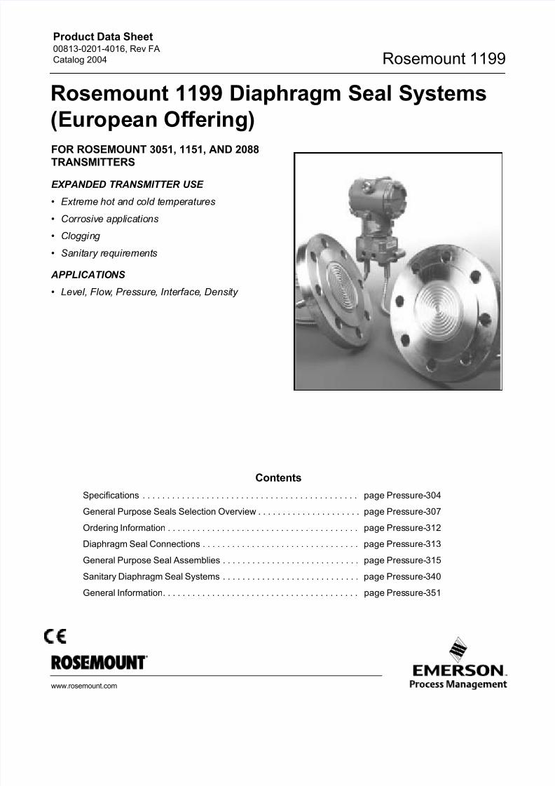
FOR ROSEMOUNT 3051, 1151, AND 2088TRANSMITTERS
EXPANDED TRANSMITTER USE
• Extreme hot and cold temperatures
• Corrosive applications
• Clogging
• Sanitary requirements
APPLICATIONS
• Level, Flow, Pressure, Interface, Density
Contents
Specifications . . . . . . . . . . . . . . . . . . . . . . . . . . . . . . . . . . . . . . . . . . . . page Pressure-304
General Purpose Seals Selection Overview . . . . . . . . . . . . . . . . . . . . . page Pressure-307
Ordering Information . . . . . . . . . . . . . . . . . . . . . . . . . . . . . . . . . . . . . . . page Pressure-312
Diaphragm Seal Connections . . . . . . . . . . . . . . . . . . . . . . . . . . . . . . . . page Pressure-313
General Purpose Seal Assemblies . . . . . . . . . . . . . . . . . . . . . . . . . . . . page Pressure-315
Sanitary Diaphragm Seal Systems . . . . . . . . . . . . . . . . . . . . . . . . . . . . page Pressure-340
General Information. . . . . . . . . . . . . . . . . . . . . . . . . . . . . . . . . . . . . . . . page Pressure-351
Rosemount 1199 Diaphragm Seal Systems
(European Offering)
Page 2
8/13/2019 4016_RevFA_catalog2004
http://slidepdf.com/reader/full/4016revfacatalog2004 2/56
Page 3
8/13/2019 4016_RevFA_catalog2004
http://slidepdf.com/reader/full/4016revfacatalog2004 3/56
Product Data Sheet00813-0201-4016, Rev FA
Catalog 2004
Pressure-305
Rosemount 1199
GASKET SPECIFICATIONSTable 5 refers to the gaskets supplied with the diaphragm seal.
TRANSMITTER SPECIFICATIONS
Functional Specifications
For complete functional, performance, and physical specifications
for the Rosemount 3051S, 3051C, Rosemount 3051T, Rosemount
1151, and Rosemount 2088 transmitters, refer to the respective
product data sheets listed in this section.
The transmitter pressure ranges and ordering codes for use with
diaphragm seals are located in Section 4 of this document.
Hazardous Locations Certifications
Adding seals to the transmitter does not change the approval
ratings of the individual transmitters. For complete approval
listings, see the respective product data sheet for the pressure
transmitter.
Maximum Working Pressure of
Transmitter–Seal System
The maximum working pressure (MWP) of the transmitter–sealsystem is a function of the MWP of the transmitter and the remote
seal. To determine the MWP of the transmitter–seal system,
simply select the lesser value of the two. For safe operation, the
MWP of the transmitter–seal system must not be exceeded.
DIN 2526 Form C, D or E Raised face
DIN 2696 Form L 'Linsen” gasket face
ANSI /ASME B16.5 Raised face ANSI /ASME B16.5 Ring type joint
TABLE 3. Available Industry Standards for General Purpose Diaphragm Seals
Standard Description
TABLE 4. Available for Sanitary Diaphragm Seals Industry Standards(1)
Standard Description
SMS: Swedish Milk Standard Female or male thread
IDF: International Dairy Federation Female or male thread
RJT: Ring Joint Type Female or male thread
DIN 11851 Female or male thread
Tri-Clamp® Sanitary
Tuchenhagen Varivent ® Sanitary
Homogenizer Clamping Flange Sanitary
(1) Other standards are available upon request.
TABLE 5. Gasket Specifications
Gasket Temperature Limit (°C)
PTFE(1)
(1) Temperature limits are in standard circumstances.
–160 to 230 °C
98% Graphite(1) –200 to 500 °C
Viton®(2)
(2) Temperature limit in oxidizing atmosphere.
–20 to 200 °C
Ethylene Propylene –55 to 150 °C
TABLE 6. Transmitter Temperature Limits Summary.
Rosemount
3051S,
3051C, 3051T
Rosemount
1151
Rosemount
2088
Ambient –40 to 85 °C S Electronics
–40 to 85 °C
–40 to 85 °C
E,G Electronics
–30 to 95 °C
Storage –45 to 110 °C S Electronics
–50 to 85 °C
–45 to 85 °C
E,G Electronics
–50 to 120 °C
Process
Silicone
Sensor
–40 to 120 °C –40 to 105 °C –40 to 120 °C
Page 4
8/13/2019 4016_RevFA_catalog2004
http://slidepdf.com/reader/full/4016revfacatalog2004 4/56
Product Data Sheet00813-0201-4016, Rev FA
Catalog 2004Rosemount 1199
Pressure-306
NACE Standard
NACE (National Association of Corrosion Engineers) standard
MR–01–75 defines metallic material requirements for resistance to
sulfide stress cracking when exposed to sour environments.
Contact your Rosemount representative to aid
in selecting the proper materials in order for Rosemountdiaphragm seals to meet the
NACE standard.
Zero Elevation and Suppression
Zero elevation and suppression must be such that the lower range
value is greater than or equal to the (–URL) and the upper range
value is less than or equal to the (+URL). The calibrated span
must be greater than or equal to the minimum span.
PHYSICAL SPECIFICATIONS
Materials of Construction
Isolating Diaphragm
Rosemount 3051S/C: 316L SST
Rosemount 3051T: 316L SST
Rosemount 1151: 316L SST
Rosemount 2088: 316L SST
Process Flange or Connector
Rosemount 3051S/C: 316 SST
Rosemount 3051T: 316L SST
Rosemount 1151: CF-8M (Cast Version of 316 SST, material per
ASTM-A743)
Rosemount 2088: 316L SST
O-ring
Rosemount 3051S/C: Glass-filled TFE
Rosemount 3051T: NoneRosemount 1151: Viton or Buna N
Rosemount 2088: None
Sensor Module Fill Fluid
Silicone Oil
Bolts (Rosemount 3051S/C and 1151 only)
Plated Carbon Steel or 316 SST
Electronics Housing
Low-copper aluminum or CF-8M (cast version of 316 SST,
material per ASTM-A743), NEMA 4X, IP66
Paint
Polyurethane
Cover O-rings
Buna-N
Electrical Connection
Rosemount 3051S, 3051C, 3051T, and Rosemount 20881/2–14 NPT, PG 13.5, G1/2 Female (PF1/2 Female, or M20 3
1.5 Female (CM20) conduit entry
Rosemount 1151
• 1/2–14 NPT conduit with screw terminals and integral test
jacks compatible with miniature banana plugs (Pomona 2944,
3690, or equivalent)
Rosemount 3051S, 3051C, 3051T, and Rosemount 1151 Smart
• The HART-based communicator connections are fixed to the
terminal block.
Transmitter Weight
The transmitter/seal system weight depends on the type of
capillary and seal:
Rosemount 3051S_C
3,3 kg without options
Rosemount 3051C
2,5 kg without options
Rosemount 3051T
1,4 kg without options
Rosemount 1151
5,5 kg without options
Rosemount 2088
1,0 kg without options
Tagging
The pressure transmitter will be tagged, at no charge, in
accordance with customer requirements. All tags are stainless
steel. The standard tag is wired to the transmitter. Tag is 0,5 mm
thick with 3,2 mm high letters. A permanently attached tag is
available upon request. The remote seal model number is
identified on the transmitter nameplate
Calibration
Transmitters are factory calibrated to customer’s specified range.
If calibration is not specified, then the transmitters are calibrated at
maximum range. Calibration is performed at ambient temperature
and pressure. Four and 20 mA points must be the same unit of
measure. Available units of measure:
Custom Configurations
Rosemount 3051S/3051C (Option Code C1)
If code C1 is ordered, the customer may specify the following
data in addition to the standard configuration parameters.
Refer to Configuration Data Sheet 00806-0100-4001.
Rosemount 1151 (Option Code C9)
If Options Code C9 is ordered, the customer may specify the
following data in addition to the standard configuration
parameters. Refer to Configuration Data Sheet
00806-0100-4593.Descriptor: 16 alphanumeric characters
Message: 32 alphanumeric characters
Date: Day, month, year
Damping: Sec.
• inH2O
• mmH2O
• ftH2O
• bar
• mbar
• Pa
• kg/cm2
• g/cm2
• torr
• atm
• psi
• mmHg
• kPa
• inHg
Page 5
8/13/2019 4016_RevFA_catalog2004
http://slidepdf.com/reader/full/4016revfacatalog2004 5/56
Product Data Sheet00813-0201-4016, Rev FA
Catalog 2004
Pressure-307
Rosemount 1199
General Purpose Seals Selection Overview
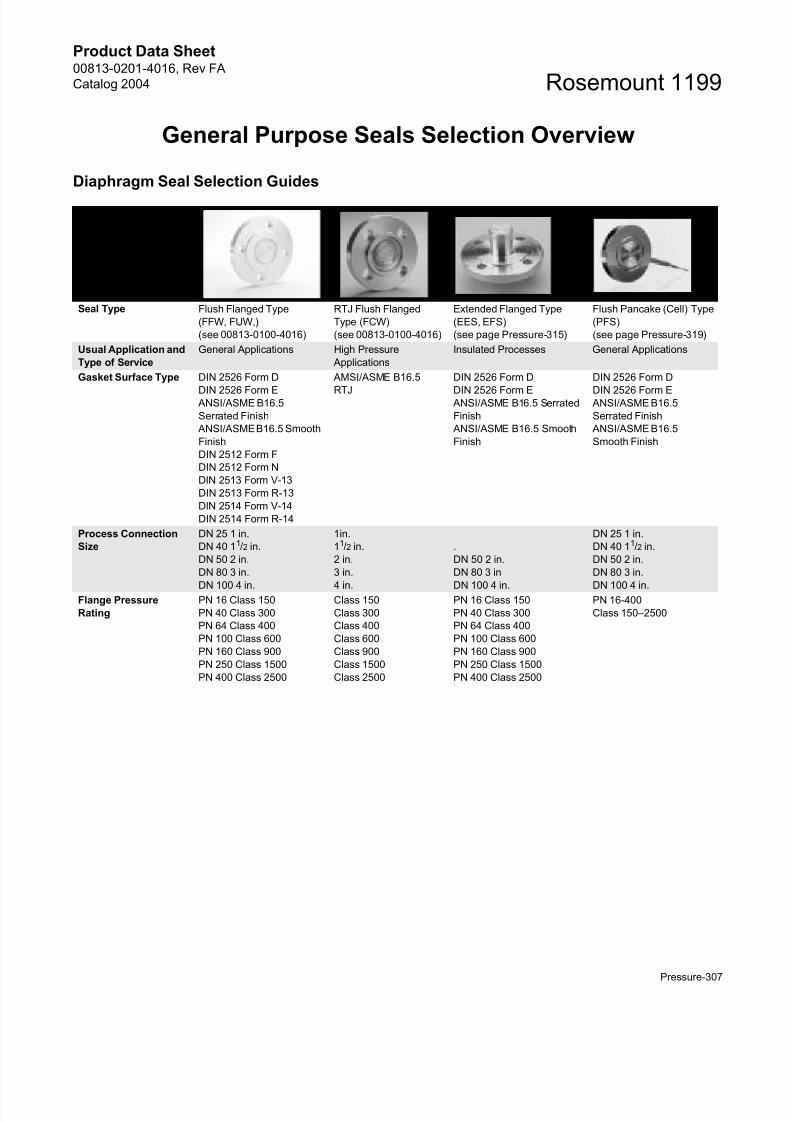
Diaphragm Seal Selection Guides
Diaphragm SealSelection Guide
Seal Type Flush Flanged Type
(FFW, FUW,)
(see 00813-0100-4016)
RTJ Flush Flanged
Type (FCW)
(see 00813-0100-4016)
Extended Flanged Type
(EES, EFS)
(see page Pressure-315)
Flush Pancake (Cell) Type
(PFS)
(see page Pressure-319)
Usual Application and
Type of Service
General Applications High Pressure
Applications
Insulated Processes General Applications
Gasket Surface Type DIN 2526 Form D
DIN 2526 Form E ANSI/ASME B16.5
Serrated Finish
ANSI/ASME B16.5 Smooth
Finish
DIN 2512 Form F
DIN 2512 Form N
DIN 2513 Form V-13
DIN 2513 Form R-13
DIN 2514 Form V-14
DIN 2514 Form R-14
AMSI/ASME B16.5
RTJ
DIN 2526 Form D
DIN 2526 Form E ANSI/ASME B16.5 Serrated
Finish
ANSI/ASME B16.5 Smooth
Finish
DIN 2526 Form D
DIN 2526 Form E ANSI/ASME B16.5
Serrated Finish
ANSI/ASME B16.5
Smooth Finish
Process Connection
Size
DN 25 1 in.
DN 40 11/2 in.
DN 50 2 in.
DN 80 3 in.
DN 100 4 in.
1in.
11/2 in.
2 in.
3 in.
4 in.
.
DN 50 2 in.
DN 80 3 in
DN 100 4 in.
DN 25 1 in.
DN 40 11/2 in.
DN 50 2 in.
DN 80 3 in.
DN 100 4 in.Flange Pressure
Rating
PN 16 Class 150
PN 40 Class 300
PN 64 Class 400
PN 100 Class 600
PN 160 Class 900
PN 250 Class 1500
PN 400 Class 2500
Class 150
Class 300
Class 400
Class 600
Class 900
Class 1500
Class 2500
PN 16 Class 150
PN 40 Class 300
PN 64 Class 400
PN 100 Class 600
PN 160 Class 900
PN 250 Class 1500
PN 400 Class 2500
PN 16-400
Class 150–2500
Page 6
8/13/2019 4016_RevFA_catalog2004
http://slidepdf.com/reader/full/4016revfacatalog2004 6/56
Product Data Sheet00813-0201-4016, Rev FA
Catalog 2004Rosemount 1199
Pressure-308
Diaphragm and
Wetted Parts Material/
Upper Housing
Material
316LSST
Monel 400®
316Ti SST (WNr 1.4571)
Titanium Gr2
Hastelloy
C-276®,B®,C-22®
Zirconium
Inconel 600®
Tantalum
Nickel 201
316LSST
316Ti SST (WNr
1.4571)Hastelloy C-276
Duplex 1.4462
316LSST
Nickel 201
316Ti SST (WNr 1.4571)
Monel 400
Hastelloy C-22, C-276, B
Inconel 600
Tantalum
Titanium Gr2
316LSST
Nickel 201
316Ti SST (WNr 1.4571)
Titanium Gr2
Hastelloy C-276, B, C-22
Monel 400
Zirconium
Tantalum
Inconel 600
Flushing Ring Material 316L SST
316Ti SST (WNr 1.4571)
Hastelloy C-276
Duplex 1.4462
316L SST
316Ti SST (WNr
1.4571)
Hastelloy C-276
Duplex 1.4462
Not Applicable 316L SST
316Ti SST (WNr 1.4571)
Hastelloy C-276
Duplex 1.4462
Options Direct Mount Connection
Material Traceability
Gold-coated 5 m
Teflon®-coated Diaphragm
Cold Temperature Fill
50 m Diaphragm
Thickness
150 m Diaphragm
Thickness
Direct Mount
Connection
Material Traceability
Teflon-coated
Diaphragm
Cold Temperature Fill
50 m Diaphragm
Thickness
150 m Diaphragm
Thickness
Direct Mount Connection
Material Traceability
Custom Extension Lengths
Cold Temperature Fill
50 m Diaphragm
Thickness
150m Diaphragm
Thickness
Material Traceability
Cold Temperature Fill
Gold-coated 5 m
Teflon-coated Diaphragm
50 m Diaphragm
Thickness
150m Diaphragm
Thickness
Diaphragm SealSelection Guide
Diaphragm SealSelection Guide
Seal Type Extended Pancake (Cell) Type
(DES, DFS)
(see page Pressure-322)
Internal Flanged Type
(RFS)
(see page Pressure-325)
Internal Threaded Type
(RTS)
(see page Pressure-328)
Usual Application and
Type of Service
Insulated Processes Small Process Connections Small Process Connections
High Pressures
Gasket Surface Type DIN 2526 Form D
DIN 2526 Form E
ANSI/ASME B16.5 Serrated Finish
ANSI/ASME B16.5 Smooth Finish
DIN 2512 Form N
DIN 2512 Form F
DIN 2513 Form V-13
DI 2513 Form R-13
DIN 2514 Form V-14
DIN 2514 Form R-14
DIN 2526 Form D
DIN 2526 Form E
ANSI/ASME B16.5 Serrated Finish
ANSI/ASME B16.5 Smooth Finish
Not Applicable
Process ConnectionSize
DN 50 2 in.
DN 80 3 in.
DN 100 4 in.
DN 125 5 in.
DN 20 1/2 in.
DN 25 3/4 in.
DN 32 11/4 in.
DN 40 11/2 in.
Parallel Thread: G1/2 A DIN 16288
Tapered Thread: R1/2 A per ISO 7/11/2 –14 NPT
1–11.5 NPT
Page 7
8/13/2019 4016_RevFA_catalog2004
http://slidepdf.com/reader/full/4016revfacatalog2004 7/56
Product Data Sheet00813-0201-4016, Rev FA
Catalog 2004
Pressure-309
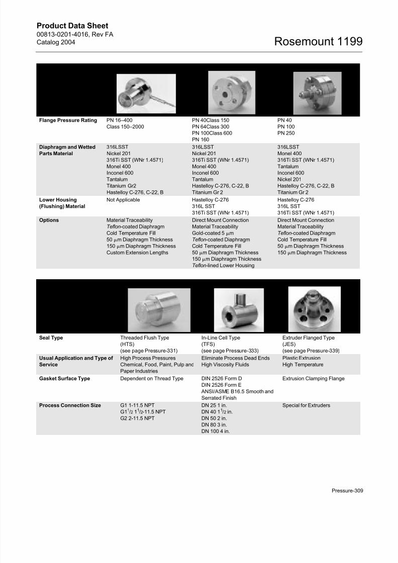
Rosemount 1199
Flange Pressure Rating PN 16–400
Class 150–2000
PN 40Class 150
PN 64Class 300
PN 100Class 600
PN 160
PN 40
PN 100
PN 250
Diaphragm and Wetted
Parts Material
316LSST
Nickel 201
316Ti SST (WNr 1.4571)
Monel 400
Inconel 600
Tantalum
Titanium Gr2
Hastelloy C-276, C-22, B
316LSST
Nickel 201
316Ti SST (WNr 1.4571)
Monel 400
Inconel 600
Tantalum
Hastelloy C-276, C-22, B
Titanium Gr 2
316LSST
Monel 400
316Ti SST (WNr 1.4571)
Tantalum
Inconel 600
Nickel 201
Hastelloy C-276, C-22, B
Titanium Gr 2
Lower Housing
(Flushing) Material
Not Applicable Hastelloy C-276
316L SST
316Ti SST (WNr 1.4571)
Hastelloy C-276
316L SST
316Ti SST (WNr 1.4571)
Options Material Traceability
Teflon-coated Diaphragm
Cold Temperature Fill
50 m Diaphragm Thickness
150 m Diaphragm Thickness
Custom Extension Lengths
Direct Mount Connection
Material Traceability
Gold-coated 5 m
Teflon-coated Diaphragm
Cold Temperature Fill
50 m Diaphragm Thickness
150 m Diaphragm Thickness
Teflon-lined Lower Housing
Direct Mount Connection
Material Traceability
Teflon-coated Diaphragm
Cold Temperature Fill
50 m Diaphragm Thickness
150 m Diaphragm Thickness
Diaphragm SealSelection Guide
Diaphragm SealSelection Guide
Seal Type Threaded Flush Type
(HTS)
(see page Pressure-331)
In-Line Cell Type
(TFS)
(see page Pressure-333)
Extruder Flanged Type
(JES)
(see page Pressure-339)
Usual Application and Type of
Service
High Process Pressures
Chemical, Food, Paint, Pulp and
Paper Industries
Eliminate Process Dead Ends
High Viscosity Fluids
Plastic Extrusion
High Temperature
Gasket Surface Type Dependent on Thread Type DIN 2526 Form D
DIN 2526 Form E
ANSI/ASME B16.5 Smooth and
Serrated Finish
Extrusion Clamping Flange
Process Connection Size G1 1-11.5 NPT
G11/2 11/2-11.5 NPT
G2 2-11.5 NPT
DN 25 1 in.
DN 40 11/2 in.
DN 50 2 in.
DN 80 3 in.
DN 100 4 in.
Special for Extruders
Page 8
8/13/2019 4016_RevFA_catalog2004
http://slidepdf.com/reader/full/4016revfacatalog2004 8/56
Product Data Sheet00813-0201-4016, Rev FA
Catalog 2004Rosemount 1199
Pressure-310
Sanitary Seal Selection Overview
Pressure Rating 600 Bar PN 16-400
Class 150-2500
400 bar
Diaphragm and Wetted Parts
Material/ Upper Housing
Material
316L SST
316Ti SST (WNr 1.4571)
316L SST
316Ti SST (WNr 1.4571)
316L SST
316Ti SST (WNr 1.4571)
Options Material Traceability
Cold Temperature Fill
50 m Diaphragm Thickness
150 m Diaphragm Thickness
Direct Mount
Material Traceability
Integral Flange Construction
Direct Mount to Rosemount
3051T or Rosemount 2088
Material Traceability
150 m Diaphragm Thickness
Custom Extension Lengths
Jock Screws
Direct Mount
Diaphragm SealSelection Guide
Sanitary SealSelection Guide
Seal Type In-Line Sanitary Type
(VLS, VMS)
(see page Pressure-340)
Dairy Type
(SLS, SMS, SFS, SRS)
(see page Pressure-342)
Dairy Type
(MLS,MMS, MFS, MRS)
(see page Pressure-344)
In-Line Sanitary Tri-Clamp
(VCS)
(see page Pressure-346)
Usual Application and
Type of Service
Food and Pharmaceutical
Industries
High Viscosity Fluids
Eliminate Process Dead
Ends
Sanitary and Food
Industry
Sanitary and Food
Industry
Food and Pharmaceutical
Industries
High Viscosity Fluids
Eliminate Process Dead
Ends
Connection Type DIN 11851 Male
SMS Male
DIN 11851 Female
SMS Female
IDF Female
RJT Female
DIN 11851 Male
SMS Male
IDF Male
RJT Male
Tri-Clamp
Process Connection
Size
DN 25 1 in.
DN 40 11/2 in.
DN 50 2 in.
DN 80 3 in.
DN 100 4 in.
DN 25 DN 65
DN 32 DN 80
DN 40 DN 100
DN 50
DN 25 DN 65
DN 32 DN 80
DN 40 DN 100
DN 50
DN 25 1 in.
DN 40 11/2 in.
DN 50 2 in.
DN 80 3 in.
DN 100 4 in.
Pressure Rating 40 bar 40 Bar 40 Bar 40 Bar
Diaphragm Material 316L SST
316Ti SST (WNr 1.4571)
316L SST
316Ti SST (WNr 1.4571)
316L SST
316Ti SST (WNr 1.4571)
316L SST
316Ti SST (WNr 1.4571)Options Electro-polished
Diaphragm
Material Traceability
Electro-polished
Diaphragm
Material Traceability
Electro-polished
Diaphragm
Material Traceability
Material Traceability
Electro-polished
Diaphragm
Page 9
8/13/2019 4016_RevFA_catalog2004
http://slidepdf.com/reader/full/4016revfacatalog2004 9/56
Product Data Sheet00813-0201-4016, Rev FA
Catalog 2004
Pressure-311
Rosemount 1199
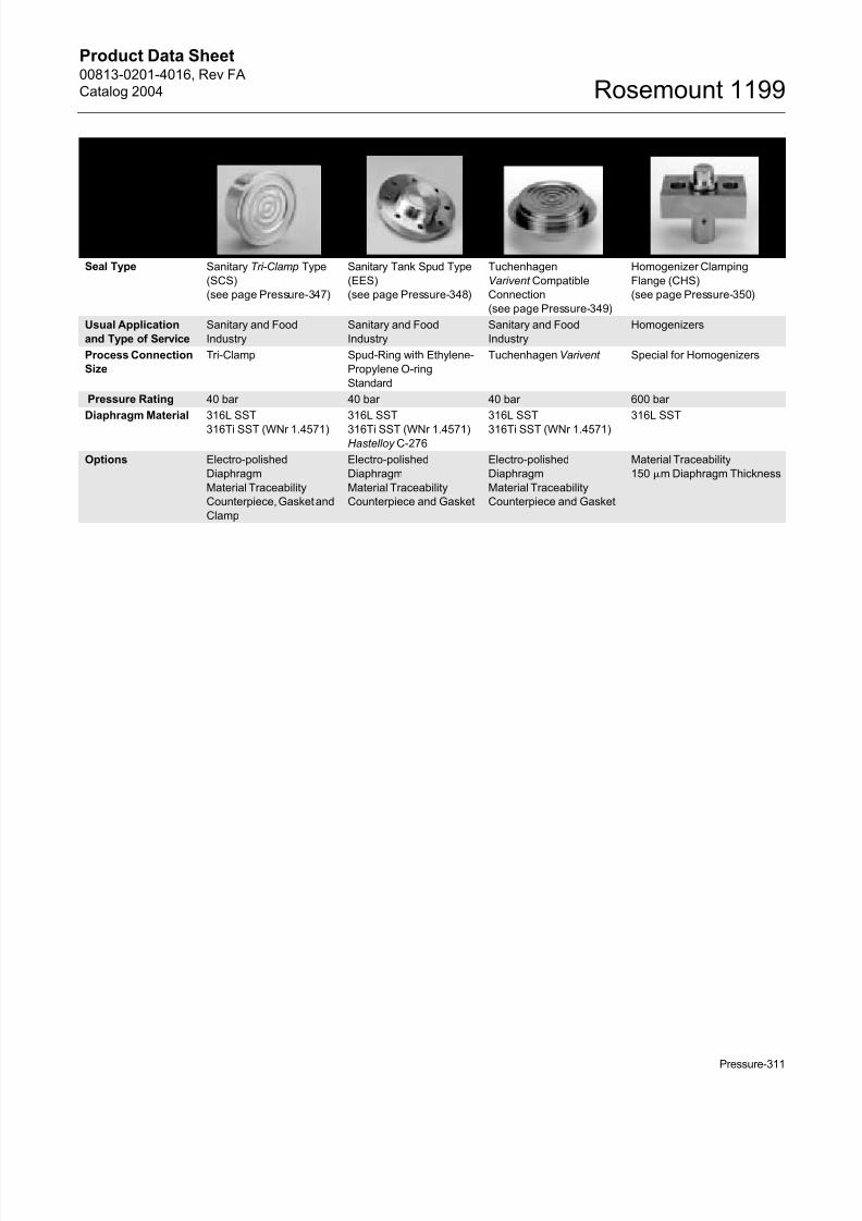
Sanitary SealSelectionGuide
Seal Type Sanitary Tri-Clamp Type
(SCS)
(see page Pressure-347)
Sanitary Tank Spud Type
(EES)
(see page Pressure-348)
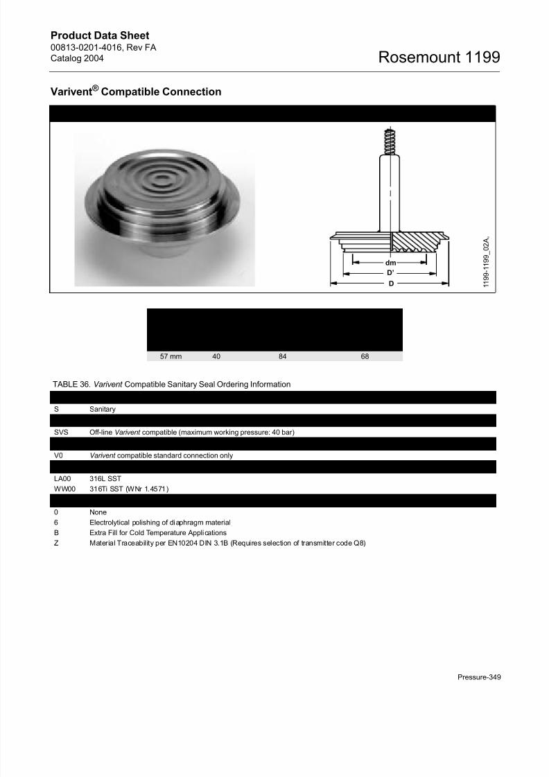
Tuchenhagen
Varivent Compatible
Connection
(see page Pressure-349)
Homogenizer Clamping
Flange (CHS)
(see page Pressure-350)
Usual Application
and Type of Service
Sanitary and Food
Industry
Sanitary and Food
Industry
Sanitary and Food
Industry
Homogenizers
Process Connection
Size
Tri-Clamp Spud-Ring with Ethylene-
Propylene O-ring
Standard
Tuchenhagen Varivent Special for Homogenizers
Pressure Rating 40 bar 40 bar 40 bar 600 bar
Diaphragm Material 316L SST
316Ti SST (WNr 1.4571)
316L SST
316Ti SST (WNr 1.4571)Hastelloy C-276
316L SST
316Ti SST (WNr 1.4571)
316L SST
Options Electro-polished
Diaphragm
Material Traceability
Counterpiece, Gasket and
Clamp
Electro-polished
Diaphragm
Material Traceability
Counterpiece and Gasket
Electro-polished
Diaphragm
Material Traceability
Counterpiece and Gasket
Material Traceability
150 m Diaphragm Thickness
Page 10
8/13/2019 4016_RevFA_catalog2004
http://slidepdf.com/reader/full/4016revfacatalog2004 10/56
Product Data Sheet00813-0201-4016, Rev FA
Catalog 2004Rosemount 1199
Pressure-312
Ordering InformationRosemount1199 Diaphragm SealSys tems (EuropeanOffering) OrderingTables
HOW TO ORDER A ROSEMOUNT
SEAL/TRANSMITTER SYSTEMThe following steps outline the transmitter/seal
system ordering process. Please review the entire
procedure before specifying a transmitter/seal
system model number.
Step 1. Select a Pressure Transmitter Model
Number
Refer to the Pressure Transmitters product data
sheets below to select a transmitter model number.
For additional transmitter information, see the
following product data sheets:
• Rosemount 3051S Series:(document number 00813-0100-4801)
• Rosemount 3051C and 3051T(document number 00813-0100-4001)
• Rosemount 2088(document number 00813-0100-4690)
• Rosemount 1151(document number 00813-0100-4360)
Step 2. Select a Seal Assembly Model Number
1. Use Table 7 on page 313 or Table 8 on
page 314 to specify a Capillary or Direct MountFill Fluid code (nine characters).
• Include a code from each section of the table.
Example: Using: “1199MD256...” is typical of the first half of
a seal assembly model number.
2. Use the Seal tables beginning on
page Pressure-313 to specify the Diaphragm Seal
Configuration.
3. Include a code from each section of the table.
• Include as many options as desired from theOptions (Multiple Selections) section.
Example: The customer wants the one piece design and a
150mm diaphragm thickness to add a vacuum resistant tothe model. The model string becomes DFFWJG0A00EC.
4. Combine the two sets of model numbers to
create one model number string. This completes
a valid seal assembly model number.
Example: Combine the model strings in steps A and B
above for a complete seal assembly model number string:
“1199MD256 DFFWJG0A00EC.”
NOTE FOR SPECIAL CONFIGURATIONS
It is possible to order two different seal assembliesfor one transmitter. Use the seal location code to
specify the attachment location for both the high and
low side seals.
For example, suppose a direct mount seal is required
on the high pressure side of the Rosemount 3051
All-Welded System and a seal with a 3 m capillary is
required for the low pressure side. In this example,
the order may look like the following:
CAUTION
While it is possible to combine different types of
seals, fill fluid and capillary lengths, be aware that
performance may be more affected by some
combinations than others. Consult with your local
Rosemount representative for assistance in seal
selection.
Quantity Model Number
1 3051CD4A22A1AS9 (From Step 1)1 1199WDAD6 DFFWJGDA00 (From Step 2)
1 1199MD356 DFFWJGDA00 (From Step 2)
Page 11
8/13/2019 4016_RevFA_catalog2004
http://slidepdf.com/reader/full/4016revfacatalog2004 11/56
Product Data Sheet00813-0201-4016, Rev FA
Catalog 2004
Pressure-313
Rosemount 1199
Diaphragm Seal ConnectionsUse Table 7 to order Capillary type connections. use Table 8 to order Direct Mount type connections.
Capillary/Fill Fluid
TABLE 7. Capillary/Fill Fluid Ordering Information(1)
Model Type
1199 Diaphragm Seal
Code Seal Location Capillary Connections
P Seal on High Pressure Side of Transmitter All welded
system
Rosemount 3051T, 2088, and
3051S2T
R Seal on High Pressure Side of Transmitter All welded
system
Rosemount 3051S2C
(option code B11)
S Seal on Low Pressure Side of Transmitter
(use with Rosemount 1199T)
All welded
system
Rosemount 3051S2C
(option code B12)
T Seal on High Pressure Side of Transmitter
(requires Rosemount 1199S on low side)
All welded
system
Rosemount 3051S2C
(option code B12)
D
W
M
Same Seal on Both High and Low Pressure Sides of Transmitter
Seal on High Pressure Side of Transmitter
Seal on Low Pressure Side of Transmitter
Welded
Welded
Welded
Code Fill Fluid
Temperature Limits(2)
Pabs < 1 bara Pabs > 1 bara Specific Gravity
D
C
A
H
N
4
D.C.200 Silicone
D.C. 704 Silicone
Syltherm XLT Silicone
Inert (Halocarbon)
Neobee M–20
Vegetable, Sanitary Oil
–45 to 100 °C
0 to 200 °C
N/A
–45 to 80 °C
–15 to 120 °C
–10 to 120 °C
–45 to 205 °C
0 to 315 °C
–75 to 150 °C
–45 to 160 °C
–15 to 225 °C
–10 to 250 °C
0,93
1,07
0,85
1,85
0,90
0,91
Code Capillary Inside Diameter (mm) Material
2 1 mm SST Armored Sleeving and Support Tubes
3 2 mm SST Armored Sleeving and Support Tubes
5 1 mm SST Armored Polyethylene Sleeving and Support Tubes
6 2 mm SST Armored Polyethylene Sleeving and Support Tubes
Code Capillary Connection Length Code Capillary Connection Length
51 0,5 m 68 14,0 m
52 1,0 m 69 15,0 m
53 1,5 m 70(3) 16 m
54 2,0 m 71(3) 17 m
55 2,5 m 72(3) 18 m
56 3,0 m 73(3) 19 m
57 3,5 m 74(3) 20 m
58 4,0 m 75(3) 21 m
59 5,0 m 76(3) 22 m
60 6,0 m 77(3) 23 m
61 7,0 m 78(3) 24 m
62 8,0 m 79(3) 25 m
63 9,0 m 80(3) 26 m
64 10,0 m 81(3) 27 m
65 11,0 m 82(3) 28 m
66 12,0 m 83(3) 29 m
67 13,0 m 84(3) 30 m
(1) Shaded Areas indicate special orders. Consult your Rosemount representative for configuration availability, performance effect, and lead time.
(2) Contact your Rosemount representative for temperature limits above 315°C.
(3) Consult your Rosemount representative to perform performance effect calculation.
Page 12
8/13/2019 4016_RevFA_catalog2004
http://slidepdf.com/reader/full/4016revfacatalog2004 12/56
Product Data Sheet00813-0201-4016, Rev FA
Catalog 2004Rosemount 1199
Pressure-314
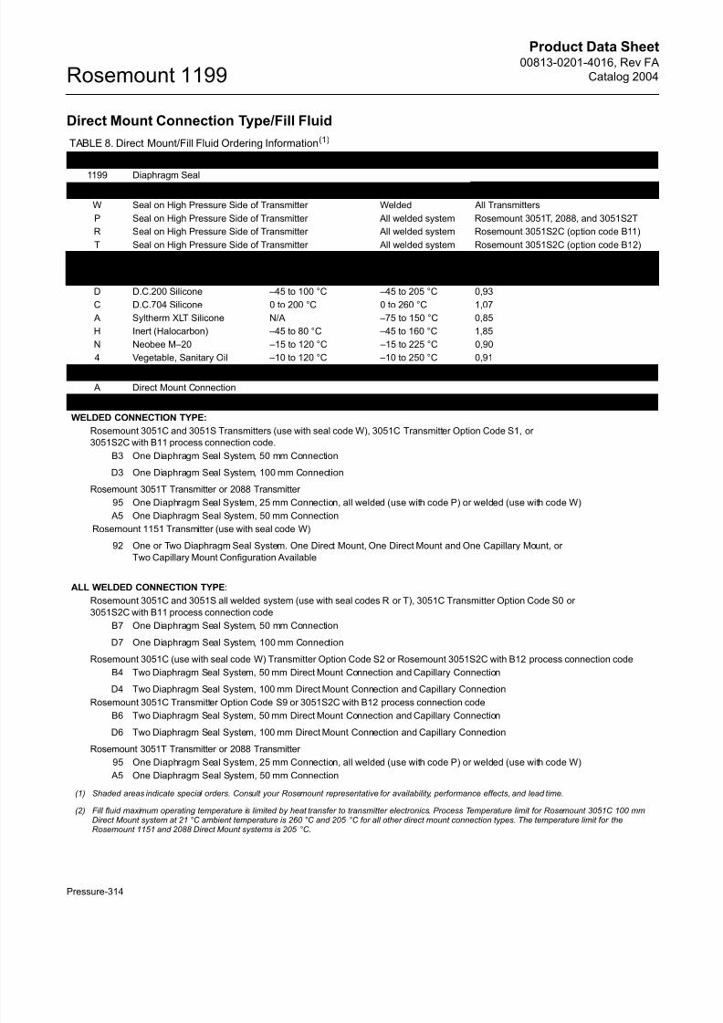
Direct Mount Connection Type/Fill Fluid
TABLE 8. Direct Mount/Fill Fluid Ordering Information(1)
Model Type
1199 Diaphragm SealCode Seal Location Connection Type Transmitter Type
W Seal on High Pressure Side of Transmitter Welded All Transmitters
P Seal on High Pressure Side of Transmitter All welded system Rosemount 3051T, 2088, and 3051S2T
R Seal on High Pressure Side of Transmitter All welded system Rosemount 3051S2C (option code B11)
T Seal on High Pressure Side of Transmitter All welded system Rosemount 3051S2C (option code B12)
Code Fill Fluid
Temperature Limits(2)
Pabs < 1 bara Pabs > 1 bara Specific Gravity
D D.C.200 Silicone –45 to 100 °C –45 to 205 °C 0,93
C D.C.704 Silicone 0 to 200 °C 0 to 260 °C 1,07
A Syltherm XLT Silicone N/A –75 to 150 °C 0,85
H Inert (Halocarbon) –45 to 80 °C –45 to 160 °C 1,85
N Neobee M–20 –15 to 120 °C –15 to 225 °C 0,90
4 Vegetable, Sanitary Oil –10 to 120 °C –10 to 250 °C 0,91Code Connection Type
A Direct Mount Connection
Code Direct Mount Connection Type
WELDED CONNECTION TYPE:
Rosemount 3051C and 3051S Transmitters (use with seal code W), 3051C Transmitter Option Code S1, or
3051S2C with B11 process connection code.
B3 One Diaphragm Seal System, 50 mm Connection
D3 One Diaphragm Seal System, 100 mm Connection
Rosemount 3051T Transmitter or 2088 Transmitter
95 One Diaphragm Seal System, 25 mm Connection, all welded (use with code P) or welded (use with code W)
A5 One Diaphragm Seal System, 50 mm Connection
Rosemount 1151 Transmitter (use with seal code W)
92 One or Two Diaphragm Seal System. One Direct Mount, One Direct Mount and One Capillary Mount, or
Two Capillary Mount Configuration Available
ALL WELDED CONNECTION TYPE:
Rosemount 3051C and 3051S all welded system (use with seal codes R or T), 3051C Transmitter Option Code S0 or
3051S2C with B11 process connection code
B7 One Diaphragm Seal System, 50 mm Connection
D7 One Diaphragm Seal System, 100 mm Connection
Rosemount 3051C (use with seal code W) Transmitter Option Code S2 or Rosemount 3051S2C with B12 process connection code
B4 Two Diaphragm Seal System, 50 mm Direct Mount Connection and Capillary Connection
D4 Two Diaphragm Seal System, 100 mm Direct Mount Connection and Capillary Connection
Rosemount 3051C Transmitter Option Code S9 or 3051S2C with B12 process connection code
B6 Two Diaphragm Seal System, 50 mm Direct Mount Connection and Capillary Connection
D6 Two Diaphragm Seal System, 100 mm Direct Mount Connection and Capillary Connection
Rosemount 3051T Transmitter or 2088 Transmitter
95 One Diaphragm Seal System, 25 mm Connection, all welded (use with code P) or welded (use with code W)
A5 One Diaphragm Seal System, 50 mm Connection
(1) Shaded areas indicate special orders. Consult your Rosemount representative for availability, performance effects, and lead time.
(2) Fill fluid maximum operating temperature is limited by heat transfer to transmitter electronics. Process Temperature limit for Rosemount 3051C 100 mmDirect Mount system at 21 °C ambient temperature is 260 °C and 205 °C for all other direct mount connection types. The temperature limit for theRosemount 1151 and 2088 Direct Mount systems is 205 °C.
Page 13
8/13/2019 4016_RevFA_catalog2004
http://slidepdf.com/reader/full/4016revfacatalog2004 13/56
Product Data Sheet00813-0201-4016, Rev FA
Catalog 2004
Pressure-315
Rosemount 1199
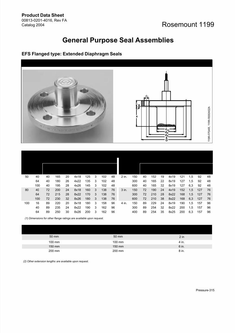
General Purpose Seal Assemblies
EFS Flanged type: Extended Diaphragm Seals
Dimensional Drawing for EFS Flanged Type: Extended Diaphragm Seal
EFS Process Connection Dimensions
DIN 2501 ANSI/ASME B16.5
DN PN(1)
Dimensions (mm)
DN CL(1)
Dimensions (mm)
dm D b d2 k f d4 d5 dm D b d2 k f d4 d5
50 40 40 165 20 4x18 125 3 102 48 2 in. 150 40 152 19 4x19 121 1,5 92 48
64 40 180 26 4x22 135 3 102 48 300 40 165 22 8x19 127 1,5 92 48
100 40 195 28 4x26 145 3 102 48 600 40 165 32 8x19 127 6,3 92 48
80 40 72 200 24 8x18 160 3 138 76 3 in. 150 72 190 24 4x19 152 1,5 127 76
64 72 215 28 8x22 170 3 138 76 300 72 210 28 8x22 168 1,5 127 76
100 72 230 32 8x26 180 3 138 76 600 72 210 38 8x22 168 6,3 127 76
100 16 89 220 20 8x18 180 3 158 96 4 in. 150 89 229 24 8x19 190 1,5 157 96
40 89 235 24 8x22 190 3 162 96 300 89 254 32 8x22 200 1,5 157 96
64 89 250 30 8x26 200 3 162 96 400 89 254 35 8x25 200 6,3 157 96
(1) Dimensions for other flange ratings are available upon request.
(2) Other extension lengths are available upon request.
b
d2
f
dmd5d4kD 1
1 9 9 - 0 7 0 A B , 1 1 9 9 - 0 0 0 0 A 0 2 A
x
Standard Extension
Lengths x (2)DIN Standard Extension
Lengths x(2)ANSI/ASME Standard
Extension Lengths x (2)
50 mm 50 mm 2 in
100 mm 100 mm 4 in.
150 mm 150 mm 6 in.
200 mm 200 mm 8 in.
Page 14
8/13/2019 4016_RevFA_catalog2004
http://slidepdf.com/reader/full/4016revfacatalog2004 14/56
Product Data Sheet00813-0201-4016, Rev FA
Catalog 2004Rosemount 1199
Pressure-316
TABLE 9. EES and EFS Flanged Type: Extended Diaphragm Seal – DIN Ordering Information(1)
Code Industry Standard
D DIN 2501 (Deutsches Institut für Normung)
Code Process Connection Style
E Flanged Type: Extended Diaphragm SealCode Gasket Surface Type
FS DIN 2526 Form D
ES DIN 2526 Form E (2)
Code Process Connection Size
G DN 50
J DN 80
K DN 100
Code Flange Pressure Rating
G PN 40
E PN 16 (DN 100 only)
H PN 64
J PN 100
K PN 160
Code Diaphragm Material(3)
Extension/Gasket Surface Material Flange/ Upper Housing MaterialLA 316L SST 316L SST 316 SST
WW 316Ti SST (WNr 1.4571) 316Ti SST (WNr 1.4571) 316 SST (WNr 1.4571)
LB Hastelloy C-276 Hastelloy C-276 316 SST
LM Hastelloy C-276 316L SST 316 SST
LC Tantalum Tantalum 316 SST
LD Tantalum 316L SST 316 SST
LR Titanium GR.2 Titanium GR.2 316 SST
LJ Hastelloy B Hastelloy B 316 SST
LP Nickel 201 Nickel 201 316 SST
L4 Hastelloy C-22 Hastelloy C-22 316 SST
LV Monel 400 Monel 400 316 SST
LE Inconel 600 Inconel 600 316 SST
Code Extension Length (4)
2 50 mm
4 100 mm6 150 mm
8 200 mm
0 0 mm
1 25 mm
3 75 mm
5 125 mm
7 175 mm
9 225 mm
Code Extension Length (Amount to Add) (4)
0 Add 0 mm
1 Add 2,5 mm
2 Add 5 mm
3 Add 7,5 mm
4 Add 10 mm
5 Add 12,5 mm
6 Add 15 mm
7 Add 17,5 mm
9 Add 22,5 mm
Code Options (Multiple Selections)
0 None
6 Add 250 mm Extension Length
7 Add 500 mm Extension Length
V Teflon Coated Diaphragm for non-stick purposes only (available with 316L SST and Hastelloy C–276 diaphragm only)
Z Material Traceability per EN10204 DIN 3.1B (Requires Selection of Transmitter Code Q8)
Page 15
8/13/2019 4016_RevFA_catalog2004
http://slidepdf.com/reader/full/4016revfacatalog2004 15/56
Product Data Sheet00813-0201-4016, Rev FA
Catalog 2004
Pressure-317
Rosemount 1199
2 Radial Capillary Connection - Available with 316L SST or 316Ti SST (WNr 1.4571) Diaphragm Material only
5 50 !m Diaphragm Thickness (available in 316L SST or Hastelloy )
8 150 !m Diaphragm Thickness - 316L SST or Hastelloy C-276 Diaphragm Material only
B Extra Fill for Cold Temperature Applications
T NACE MR–01–75
(1) Shaded areas indicate special orders. Consult your Rosemount representative for availability, performance effects, and lead time
(2) Select for Tantalum and Titanium wetted parts only.
(3) When ordering special diaphragm materials, the standard housing material is 316L SST unless noted otherwise. Consult your Rosemount representativefor use with spiral wound gaskets.
(4) DIN extension lengths are specified in millimeters as offered. Additional lengths are available as special orders. Consult factory.
TABLE 10. EES and EFS Flanged Type: Extended Diaphragm Seal –ANSI Ordering Information(1)
Code Industry Standard
A ANSI/ASME B16.5 (American National Standards Institute/American Society of Mechanical Engineers)
Code Process Connection Style
E Flanged Type: Extended Diaphragm Seal
Code Gasket Surface Type
FS Serrated Finish
ES Smooth Finish (2)
Code Process Connection Size
G 2 in.
7 3 in.
9 4 in.
Code Flange Pressure Rating
1 Class 150
2 Class 300
3 Class 400
4 Class 600
5 Class 900
6 Class 1500
7 Class 2500
Code Diaphragm Material(3) Extension/Gasket Surface Material Flange/Upper Housing Material
LA 316L SST 316L SST 316 SST
LB Hastelloy C-276 Hastelloy C-276 316 SST
LM Hastelloy C-276 316L SST 316 SST
LC Tantalum Tantalum 316 SST
LD Tantalum 316L SST 316 SST
LR Titanium GR.2 Titanium GR.2 316 SST
LJ Hastelloy B Hastelloy B 316 SST
LP Nickel 201 Nickel 201 316 SST
L4 Hastelloy C-22 Hastelloy C-22 316 SST
LV Monel 400 Monel 400 316 SST
LE Inconel 600 Inconel 600 316 SST
Code Extension Length(4)
2 2 in.
4 4 in.
6 6 in.
8 8 in.
0 0 in.
1 1 in.
3 3 in.
5 5 in.
7 7 in.
9 9 in.
TABLE 9. EES and EFS Flanged Type: Extended Diaphragm Seal – DIN Ordering Information(1)
Page 16
8/13/2019 4016_RevFA_catalog2004
http://slidepdf.com/reader/full/4016revfacatalog2004 16/56
Product Data Sheet00813-0201-4016, Rev FA
Catalog 2004Rosemount 1199
Pressure-318
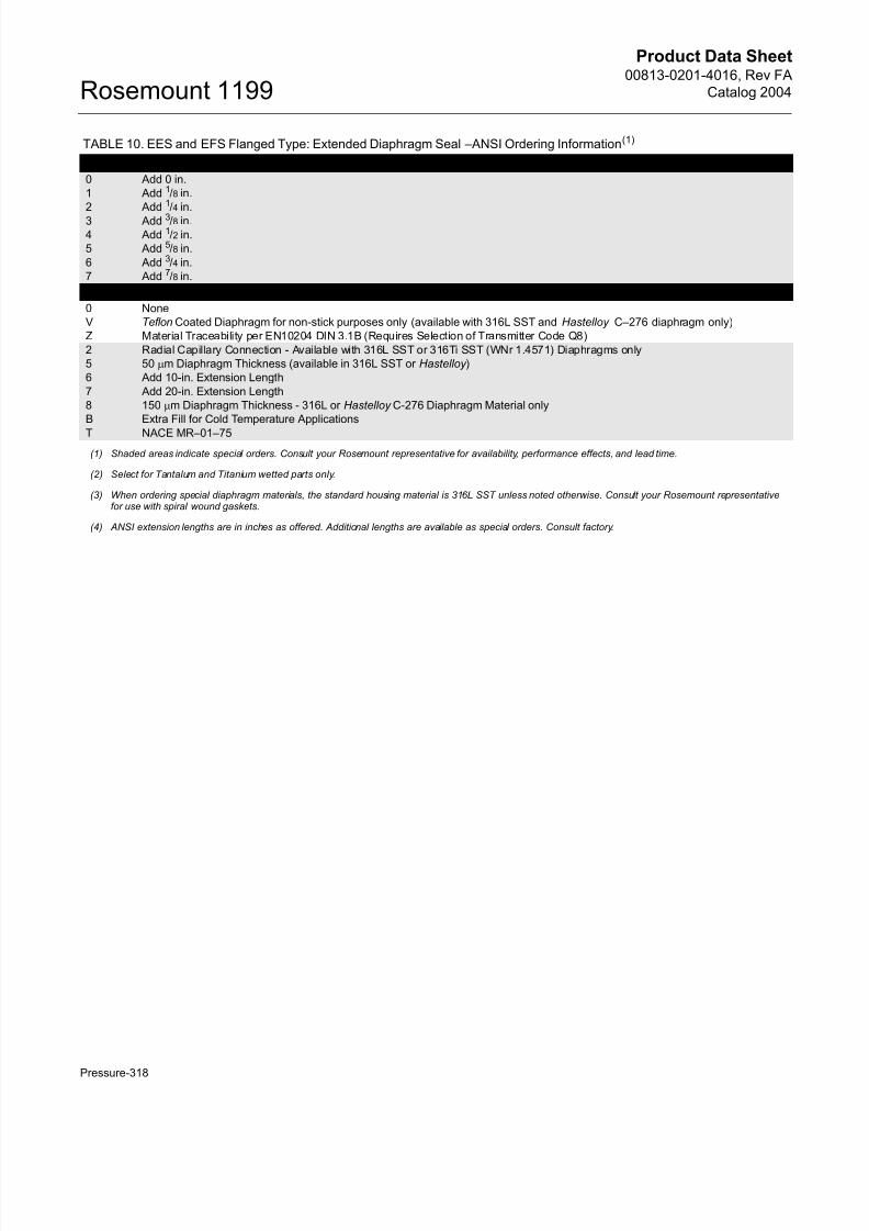
Code Extension Length (Amount to Add)
0 Add 0 in.
1 Add 1/8 in.
2 Add 1/4 in.
3 Add 3/8 in.
4 Add 1/2 in.
5 Add 5/8 in.
6 Add 3/4 in.
7 Add 7/8 in.
Code Options (Multiple Selections)
0 None
V Teflon Coated Diaphragm for non-stick purposes only (available with 316L SST and Hastelloy C–276 diaphragm only)
Z Material Traceability per EN10204 DIN 3.1B (Requires Selection of Transmitter Code Q8)
2 Radial Capillary Connection - Available with 316L SST or 316Ti SST (WNr 1.4571) Diaphragms only
5 50 !m Diaphragm Thickness (available in 316L SST or Hastelloy )
6 Add 10-in. Extension Length
7 Add 20-in. Extension Length
8 150 !m Diaphragm Thickness - 316L or Hastelloy C-276 Diaphragm Material only
B Extra Fill for Cold Temperature Applications
T NACE MR–01–75
(1) Shaded areas indicate special orders. Consult your Rosemount representative for availability, performance effects, and lead time.
(2) Select for Tantalum and Titanium wetted parts only.
(3) When ordering special diaphragm materials, the standard housing material is 316L SST unless noted otherwise. Consult your Rosemount representativefor use with spiral wound gaskets.
(4) ANSI extension lengths are in inches as offered. Additional lengths are available as special orders. Consult factory.
TABLE 10. EES and EFS Flanged Type: Extended Diaphragm Seal –ANSI Ordering Information(1)
Page 17
8/13/2019 4016_RevFA_catalog2004
http://slidepdf.com/reader/full/4016revfacatalog2004 17/56
Product Data Sheet00813-0201-4016, Rev FA
Catalog 2004
Pressure-319
Rosemount 1199
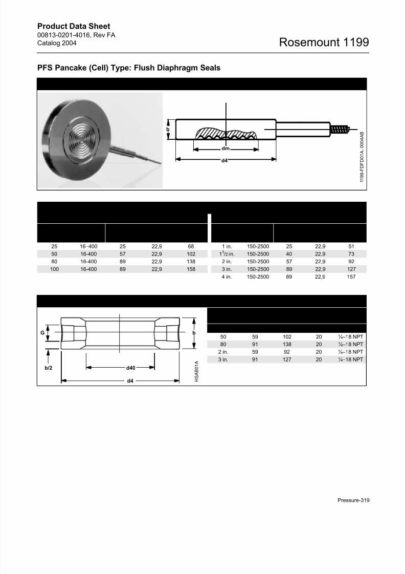
PFS Pancake (Cell) Type: Flush Diaphragm Seals
Dimensional Drawing for PFS Pancake (Cell) Type: Flush Diaphragm Seal
1 1 9 9 - F D F D 0 1 A , 0 0 0 4 A B
d4
b
dm
PFS Process Connection Dimensions
DIN 2501 ANSI/ASME B16.5
DN PN
Dimensions (mm)
DN PN
Dimensions (mm)
dm b d4 dm b d4
25 16–400 25 22,9 68 1 in. 150-2500 25 22,9 51
50 16-400 57 22,9 102 11/2 in. 150-2500 40 22,9 73
80 16-400 89 22,9 138 2 in. 150-2500 57 22,9 92
100 16-400 89 22,9 158 3 in. 150-2500 89 22,9 127
4 in. 150-2500 89 22,9 157
Dimensional Drawing for PFS Flushing Connection Ring Flushing Ring
Dimensions (mm)
DN d40 d4 b G
50 59 102 20 ¼–18 NPT
80 91 138 20 ¼–18 NPT
2 in. 59 92 20 ¼–18 NPT
3 in. 91 127 20 ¼–18 NPT
d4
d40
b
H S A B 0 1 A
b/2
G
Page 18
8/13/2019 4016_RevFA_catalog2004
http://slidepdf.com/reader/full/4016revfacatalog2004 18/56
Product Data Sheet00813-0201-4016, Rev FA
Catalog 2004Rosemount 1199
Pressure-320
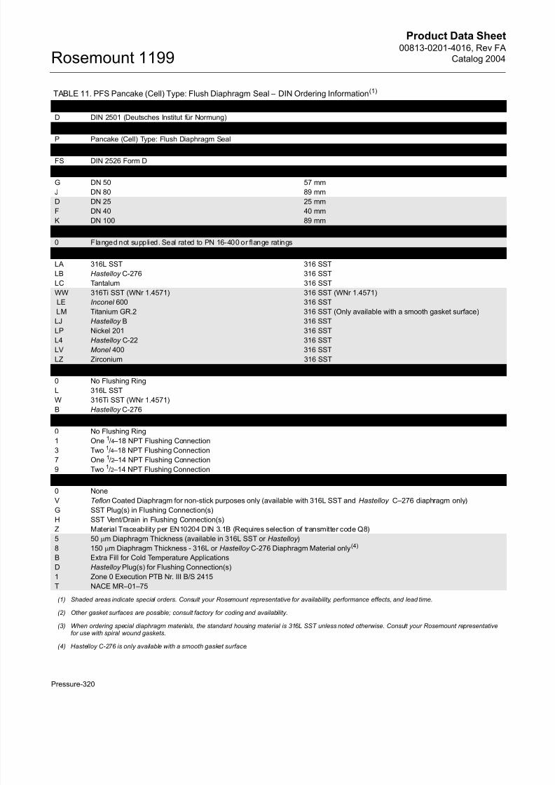
TABLE 11. PFS Pancake (Cell) Type: Flush Diaphragm Seal – DIN Ordering Information(1)
Code Industry Standard
D DIN 2501 (Deutsches Institut für Normung)
Code Process Connection Style
P Pancake (Cell) Type: Flush Diaphragm Seal
Code Gasket Surface Type(2)
FS DIN 2526 Form D
Code Process Connection Size Diaphragm Diameter
G DN 50 57 mm
J DN 80 89 mm
D DN 25 25 mm
F DN 40 40 mm
K DN 100 89 mm
Code Pressure Rating
0 Flanged not supplied. Seal rated to PN 16-400 or flange rat ings
Code Diaphragm and Wetted Parts Material(3) Upper Housing Material
LA 316L SST 316 SST
LB Hastelloy C-276 316 SSTLC Tantalum 316 SST
WW 316Ti SST (WNr 1.4571) 316 SST (WNr 1.4571)
LE Inconel 600 316 SST
LM Titanium GR.2 316 SST (Only available with a smooth gasket surface)
LJ Hastelloy B 316 SST
LP Nickel 201 316 SST
L4 Hastelloy C-22 316 SST
LV Monel 400 316 SST
LZ Zirconium 316 SST
Code Flushing Ring Material
0 No Flushing Ring
L 316L SST
W 316Ti SST (WNr 1.4571)
B Hastelloy C-276Code Flushing Options
0 No Flushing Ring
1 One 1/4 –18 NPT Flushing Connection
3 Two 1/4 –18 NPT Flushing Connection
7 One 1/2 –14 NPT Flushing Connection
9 Two 1/2 –14 NPT Flushing Connection
Code Options (Multiple Selections)
0 None
V Teflon Coated Diaphragm for non-stick purposes only (available with 316L SST and Hastelloy C–276 diaphragm only)
G SST Plug(s) in Flushing Connection(s)
H SST Vent/Drain in Flushing Connection(s)
Z Material Traceability per EN10204 DIN 3.1B (Requires selection of transmitter code Q8)
5 50 !m Diaphragm Thickness (available in 316L SST or Hastelloy )
8 150 !m Diaphragm Thickness - 316L or Hastelloy C-276 Diaphragm Material only(4)
B Extra Fill for Cold Temperature Applications
D Hastelloy Plug(s) for Flushing Connection(s)
1 Zone 0 Execution PTB Nr. III B/S 2415
T NACE MR–01–75
(1) Shaded areas indicate special orders. Consult your Rosemount representative for availability, performance effects, and lead time.
(2) Other gasket surfaces are possible; consult factory for coding and availability.
(3) When ordering special diaphragm materials, the standard housing material is 316L SST unless noted otherwise. Consult your Rosemount representativefor use with spiral wound gaskets.
(4) Hastelloy C-276 is only available with a smooth gasket surface.
Page 19
8/13/2019 4016_RevFA_catalog2004
http://slidepdf.com/reader/full/4016revfacatalog2004 19/56
Product Data Sheet00813-0201-4016, Rev FA
Catalog 2004
Pressure-321
Rosemount 1199
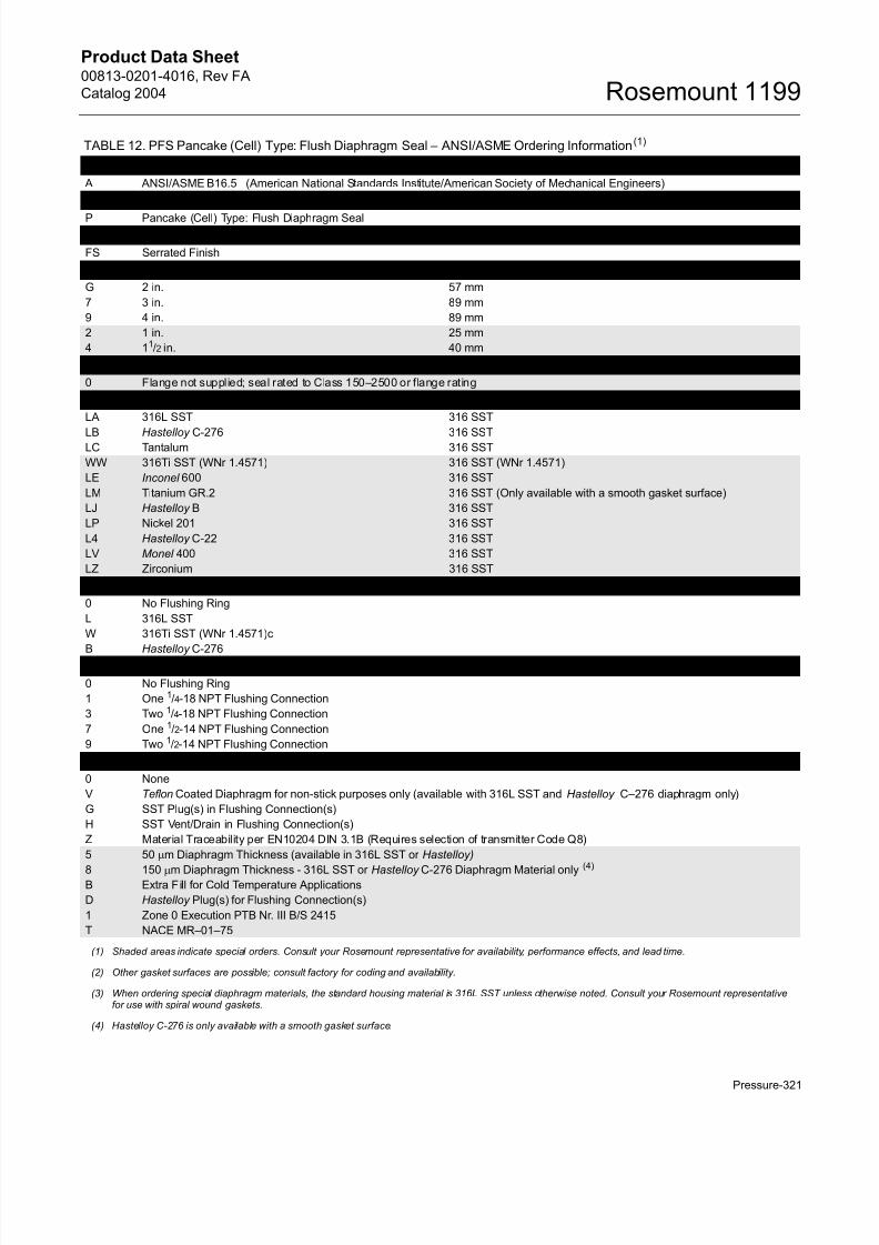
TABLE 12. PFS Pancake (Cell) Type: Flush Diaphragm Seal – ANSI/ASME Ordering Information(1)
Code Industry Standard
A ANSI/ASME B16.5 (American National Standards Institute/American Society of Mechanical Engineers)
Code Process Connection Style
P Pancake (Cell) Type: Flush Diaphragm SealCode Gasket Surface Type(2)
FS Serrated Finish
Code Process Connection Size Diaphragm Diameter
G 2 in. 57 mm
7 3 in. 89 mm
9 4 in. 89 mm
2 1 in. 25 mm
4 11/2 in. 40 mm
Code Flange Pressure Rating
0 Flange not supplied; seal rated to Class 150–2500 or flange rating
Code Diaphragm and Wetted Parts Material(3) Upper Housing Material
LA 316L SST 316 SST
LB Hastelloy C-276 316 SSTLC Tantalum 316 SST
WW 316Ti SST (WNr 1.4571) 316 SST (WNr 1.4571)
LE Inconel 600 316 SST
LM Titanium GR.2 316 SST (Only available with a smooth gasket surface)
LJ Hastelloy B 316 SST
LP Nickel 201 316 SST
L4 Hastelloy C-22 316 SST
LV Monel 400 316 SST
LZ Zirconium 316 SST
Code Flushing Ring Material
0 No Flushing Ring
L 316L SST
W 316Ti SST (WNr 1.4571)c
B Hastelloy C-276Code Flushing Options
0 No Flushing Ring
1 One 1/4-18 NPT Flushing Connection
3 Two 1/4-18 NPT Flushing Connection
7 One 1/2-14 NPT Flushing Connection
9 Two 1/2-14 NPT Flushing Connection
Code Options (Multiple Selections)
0 None
V Teflon Coated Diaphragm for non-stick purposes only (available with 316L SST and Hastelloy C–276 diaphragm only)
G SST Plug(s) in Flushing Connection(s)
H SST Vent/Drain in Flushing Connection(s)
Z Material Traceability per EN10204 DIN 3.1B (Requires selection of transmitter Code Q8)
5 50 !m Diaphragm Thickness (available in 316L SST or Hastelloy)
8 150 !m Diaphragm Thickness - 316L SST or Hastelloy C-276 Diaphragm Material only(4)
B Extra Fill for Cold Temperature Applications
D Hastelloy Plug(s) for Flushing Connection(s)
1 Zone 0 Execution PTB Nr. III B/S 2415
T NACE MR–01–75
(1) Shaded areas indicate special orders. Consult your Rosemount representative for availability, performance effects, and lead time.
(2) Other gasket surfaces are possible; consult factory for coding and availability.
(3) When ordering special diaphragm materials, the standard housing material is 316L SST unless otherwise noted. Consult your Rosemount representativefor use with spiral wound gaskets.
(4) Hastelloy C-276 is only available with a smooth gasket surface.
Page 20
8/13/2019 4016_RevFA_catalog2004
http://slidepdf.com/reader/full/4016revfacatalog2004 20/56
Product Data Sheet00813-0201-4016, Rev FA
Catalog 2004Rosemount 1199
Pressure-322
DES and DFS Pancake (Cell) Type: Extended Diaphragm Seals
Dimensional Drawing for DES and DFS Pancake Type: Extended Diaphragm Seals
1 1 9 9 - 0 0 0 6 A B
DIN Standard
Extension
Lengths x(1)
ANSI/ASME
Standard Extension
Lengths x (1)
(1) Other extension lengths are availableupon request.
50 mm 2 in
100 mm 4 in.
150 mm 6 in.
200 mm 8 in.
b
dm
d5
d4 1
1 9 9 - E D B 0 1 A
x
DES and DFS Pancake (Cell) Process Connection Dimensions
DIN 2501 ANSI/ASME B16.5
DN PN
Dimensions (mm)
DN CL
Dimensions (mm)
dm b d4 d5 dm b d4 d5
50 16-400 40 20 102 48 2 in. 150-2500 40 20 92 48
80 16-400 72 20 138 76 3 in. 150-2500 72 20 127 76
100 16-400 89 20 162 96 4 in. 150-2500 89 20 157 96
Page 21
8/13/2019 4016_RevFA_catalog2004
http://slidepdf.com/reader/full/4016revfacatalog2004 21/56
Product Data Sheet00813-0201-4016, Rev FA
Catalog 2004
Pressure-323
Rosemount 1199
TABLE 13. DES and DFS Pancake (Cell) Type: Extended Diaphragm Seal – DIN Ordering Information(1)
Code Industry Standard
D DIN 2501 (Deutsches Institut für Normung)
Code Process Connection Style
D Pancake (Cell) Type: Extended Diaphragm SealCode Gasket Surface Type
FS DIN 2526 Form D
ES DIN 2526 Form E (2)
Code Process Connection Size
G DN 50
J DN 80
K DN 100
Code Pressure Rating
0 Flange not supplied; seal rated to PN 16-400 or f lange rating
Code Diaphragm Material(3)Extension/Gasket
Surface Material
LA 316L SST 316L SST
WW 316Ti SST (WNr 1.4571) 316Ti SST (WNr 1.4571)
LB Hastelloy C-276 Hastelloy C-276LC Tantalum Tantalum
LE Inconel 600 Inconel 600
LR Titanium GR.2 Titanium GR.2
LJ Hastelloy B Hastelloy B
LP Nickel 201 Nickel 201
L4 Hastelloy C-22 Hastelloy C-22
LV Monel 400 Monel 400
LD Tantalum 316L SST
LM Hastelloy C-276 316L SST
Code Extension Length(4) Code Extension Length
2 50 mm 0 0 mm
4 100 mm 1 25 mm
6 150 mm 3 75 mm
8 200 mm 5 125 mm
7 175 mm
9 225 mm
Code Extension Length (Amount to Add)(4) Code Extension Length (Amount to Add)(4)
0 Add 0 mm 5 Add 12,5 mm
1 Add 2,5 mm 6 Add 15 mm
2 Add 5 mm 7 Add 17,5 mm
3 Add 7,5 mm 8 Add 20 mm
4 Add 10 mm 9 Add 22,5 mm
Code Options (Multiple Selections)
0 None
V Teflon Coated Diaphragm for non-stick purposes only (available with 316L SST and Hastelloy C–276 diaphragm only)
Z Material Traceability per EN10204 DIN 3.1B (Requires selection of transmitter Code Q8)
5 50 !m Diaphragm Thickness (available in 316L SST or Hastelloy )
8 150 !m Diaphragm Thickness - 316L SST or Hastelloy C-276 Diaphragm Material only
6 Add 250 mm Extension Length
7 Add 500 mm Extension Length
B Extra Fill for Cold Temperature Applications
T NACE MR–01–75
(1) Shaded areas indicate special orders. Consult your Rosemount representative for availability, performance effects, and lead time.
(2) Select for Tantalum wetted parts only.
(3) When ordering special diaphragm materials, the standard housing material is 316L SST unless noted otherwise. Consult your Rosemount representativefor use with spiral wound gaskets.
(4) DIN extension lengths are specified in millimeters, as offered. Other extension lengths are available as special offers on request.
Page 22
8/13/2019 4016_RevFA_catalog2004
http://slidepdf.com/reader/full/4016revfacatalog2004 22/56
Product Data Sheet00813-0201-4016, Rev FA
Catalog 2004Rosemount 1199
Pressure-324
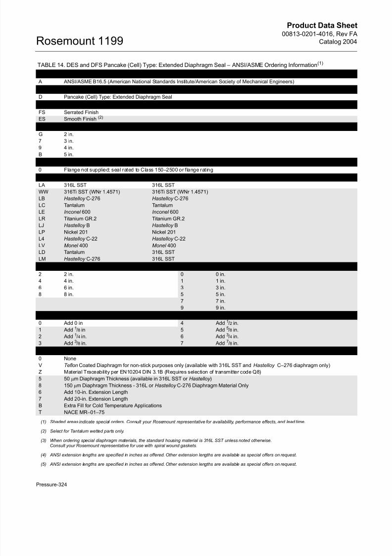
TABLE 14. DES and DFS Pancake (Cell) Type: Extended Diaphragm Seal – ANSI/ASME Ordering Information(1)
Code Industry Standard
A ANSI/ASME B16.5 (American National Standards Institute/American Society of Mechanical Engineers)
Code Process Connection Style
D Pancake (Cell) Type: Extended Diaphragm SealCode Gasket Surface Type
FS Serrated Finish
ES Smooth Finish (2)
Code Process Connection Size
G 2 in.
7 3 in.
9 4 in.
B 5 in.
Code Pressure Rating
0 Flange not supplied; seal rated to Class 150–2500 or flange rating
Code Diaphragm Material (3) Extension/Gasket Surface Material
LA 316L SST 316L SST
WW 316Ti SST (WNr 1.4571) 316Ti SST (WNr 1.4571)
LB Hastelloy C-276 Hastelloy C-276
LC Tantalum Tantalum
LE Inconel 600 Inconel 600
LR Titanium GR.2 Titanium GR.2
LJ Hastelloy B Hastelloy B
LP Nickel 201 Nickel 201
L4 Hastelloy C-22 Hastelloy C-22
LV Monel 400 Monel 400
LD Tantalum 316L SST
LM Hastelloy C-276 316L SST
Code Extension Length(4) Extension Length(5)
2 2 in. 0 0 in.
4 4 in. 1 1 in.
6 6 in. 3 3 in.
8 8 in. 5 5 in.
7 7 in.
9 9 in.
Code Extension Length (Amount to Add) Code Extension Length (Amount to Add)
0 Add 0 in 4 Add 1/2 in.
1 Add 1/8 in 5 Add 5/8 in.
2 Add 1/4 in. 6 Add 3/4 in.
3 Add 3/8 in. 7 Add 7/8 in.
Code Options (Multiple Selections)
0 None
V Teflon Coated Diaphragm for non-stick purposes only (available with 316L SST and Hastelloy C–276 diaphragm only)
Z Material Traceability per EN10204 DIN 3.1B (Requires selection of transmitter code Q8)
5 50 !m Diaphragm Thickness (available in 316L SST or Hastelloy )
8 150 !m Diaphragm Thickness - 316L or Hastelloy C-276 Diaphragm Material Only
6 Add 10-in. Extension Length
7 Add 20-in. Extension Length
B Extra Fill for Cold Temperature Applications
T NACE MR–01–75
(1) Shaded areas indicate special orders. Consult your Rosemount representative for availability, performance effects, and lead time.
(2) Select for Tantalum wetted parts only.
(3) When ordering special diaphragm materials, the standard housing material is 316L SST unless noted otherwise.Consult your Rosemount representative for use with spiral wound gaskets.
(4) ANSI extension lengths are specified in inches as offered. Other extension lengths are available as special offers on request.
(5) ANSI extension lengths are specified in inches as offered. Other extension lengths are available as special offers on request.
Page 23
8/13/2019 4016_RevFA_catalog2004
http://slidepdf.com/reader/full/4016revfacatalog2004 23/56
Product Data Sheet00813-0201-4016, Rev FA
Catalog 2004
Pressure-325
Rosemount 1199
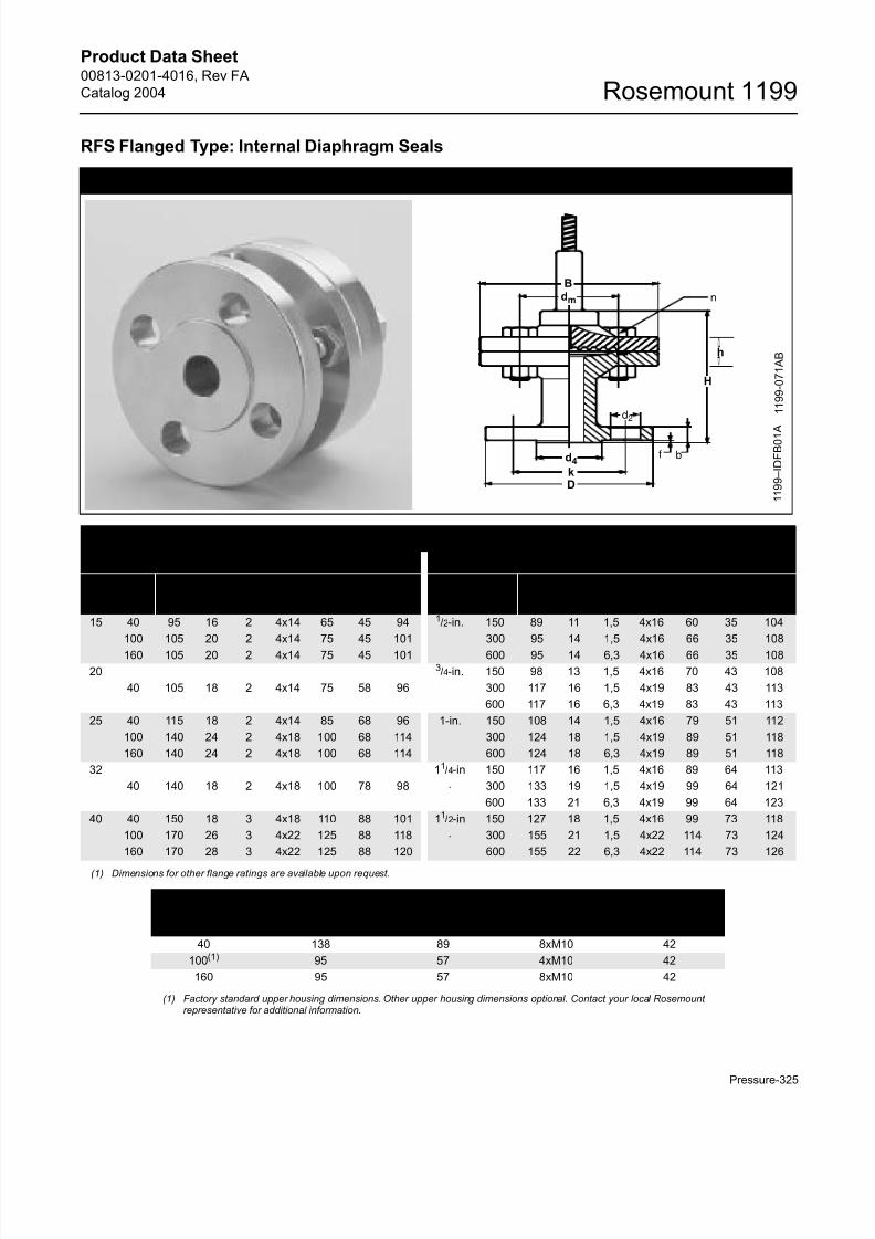
RFS Flanged Type: Internal Diaphragm Seals
Dimensional Drawing for RFS Flanged Type: Internal Diaphragm Seal
RFS Dimensions for Process Flange to Lower Housing Connection
DIN 2501 ANSI/ASME B16.5
DN PN(1)
(1) Dimensions for other flange ratings are available upon request.
Dimensions (mm)
DN CL(1)
Dimensions (mm)
D b f d2 k d4 H ca. D b f d2 k d4 H ca.
15 40 95 16 2 4x14 65 45 94 1/2-in. 150 89 11 1,5 4x16 60 35 104
100 105 20 2 4x14 75 45 101 300 95 14 1,5 4x16 66 35 108
160 105 20 2 4x14 75 45 101 600 95 14 6,3 4x16 66 35 108
20 3/4-in. 150 98 13 1,5 4x16 70 43 108
40 105 18 2 4x14 75 58 96 300 117 16 1,5 4x19 83 43 113
600 117 16 6,3 4x19 83 43 113
25 40 115 18 2 4x14 85 68 96 1-in. 150 108 14 1,5 4x16 79 51 112
100 140 24 2 4x18 100 68 114 300 124 18 1,5 4x19 89 51 118
160 140 24 2 4x18 100 68 114 600 124 18 6,3 4x19 89 51 118
32 11/4-in
.
150 117 16 1,5 4x16 89 64 113
40 140 18 2 4x18 100 78 98 300 133 19 1,5 4x19 99 64 121
600 133 21 6,3 4x19 99 64 123
40 40 150 18 3 4x18 110 88 101 11/2-in
.
150 127 18 1,5 4x16 99 73 118
100 170 26 3 4x22 125 88 118 300 155 21 1,5 4x22 114 73 124
160 170 28 3 4x22 125 88 120 600 155 22 6,3 4x22 114 73 126
RFS Dimensions for Upper Housing to Lower Housing Connection
PN B dm n h
40 138 89 8xM10 42
100(1)
(1) Factory standard upper housing dimensions. Other upper housing dimensions optional. Contact your local Rosemountrepresentative for additional information.
95 57 4xM10 42
160 95 57 8xM10 42
1 1 9 9 – I D F B 0 1 A
d2
f b
n
B
h
d4
kD
1 1 9 9 - 0 7 1 A B
H
dm
Page 24
8/13/2019 4016_RevFA_catalog2004
http://slidepdf.com/reader/full/4016revfacatalog2004 24/56
Product Data Sheet00813-0201-4016, Rev FA
Catalog 2004Rosemount 1199
Pressure-326
TABLE 15. RFS Flanged Type: Internal Diaphragm Seal — DIN Ordering Information(1)
Code Industry Standard
D DIN 2501 (Deutsches Institut für Normung)
Code Process Connection Type
R Flanged Type: Internal Diaphragm SealCode Gasket Surface Type(2)
FS DIN 2526 Form D
Code Process Connection Size Diaphragm Size
B DN 15 57 mm
C DN 20 57 mm
D DN 25 57 mm
E DN 32 57 mm
F DN 40 57 mm
Code Flange Pressure Rating
G PN 40
J PN 100 (n/a with DN 20 or DN 32)
K PN 160
Code(3) Diaphragm Material Upper and Lower Housing Material
LA 316L SST 316 SSTWW 316Ti SST (WNr 1.4571) 316Ti SST (WNr 1.4571)
LB Hastelloy C-276 316 SST
LC Tantalum 316 SST
LE Inconel 600 316 SST
LJ Hastelloy B 316 SST
LP Nickel 201 316 SST
L4 Hastelloy C-22 316 SST
LV Monel 400 316 SST
LZ Zirconium 316 SST
WC Tantalum 316Ti SST (WNr 1.4571)
WB Hastelloy C-276 316Ti SST (WNr 1.4571)
Code Lower Housing Material (Supplied with Viton Gasket)(4)
L 316L SST
W 316Ti SST (WNr 1.4571)
B Hastelloy C-276Code Flushing Options
1 One 1/4-18 NPT Flushing Connection
3 Two 1/4-18 NPT Flushing Connection
5 No Flushing Connection
Code Options (Multiple Selections)
0 None
2 98% Graphite Gasket
V Teflon Coated Diaphragm for non-stick purposes only (available with 316L SST and Hastelloy C–276 diaphragm only)
D Hastelloy Plug(s) for flushing connection(s)
G SST Plug(s) for flushing connection(s)
H SST Vent/Drain for flushing connection(s)
Z Material Traceability per EN10204 DIN 3.1B (Requires selection of transmitter Code Q8)
J Teflon Gasket
5 50 !m Diaphragm Thickness (available in 316L SST or Hastelloy )
8 150 !m Diaphragm Thickness - 316L or Hastelloy C-276 Diaphragm Material onlyU Gold Coated Diaphragm (5 microns)
B Extra Fill for Cold Temperature Applications
7 89 mm Diaphragm Diameter (PN 40 only)
T NACE MR–01–75
(1) Shaded areas indicate special orders. Consult your Rosemount representative for availability, performance effects, and lead time.
(2) Other gasket surfaces are possible; consult factory for coding and availability.
(3) When ordering special diaphragm materials, the standard housing material is 316L SST unless noted otherwise.
Page 25
8/13/2019 4016_RevFA_catalog2004
http://slidepdf.com/reader/full/4016revfacatalog2004 25/56
Product Data Sheet00813-0201-4016, Rev FA
Catalog 2004
Pressure-327
Rosemount 1199
TABLE 16. RFS Internal Flanged Diaphragm Seal — ANSI/ASME Ordering Information(1)
Code Industry Standard
A ANSI /ASME B16.5 (American National Standards Institute/American Society of Mechanical Engineers)
Code Process Connection Type
R Flanged Type: Internal Diaphragm SealCode Gasket Surface Type(2)
FS Serrated Finish
Code Process Connection Size Diaphragm Size
1 1/2 in. 57 mm
A 3/4 in. 57 mm
2 1 in. 57 mm
3 1 ¼in. 57 mm
4 1 ½ in. 57 mm
Code Flange Pressure Rating
1 Class 150
2 Class 300
3 Class 600
Code(3) Diaphragm Material Upper and Lower Housing Material
LA 316L SST 316 SSTWW 316Ti SST (WNr 1.4571) 316Ti SST (WNr 1.4571)
LB Hastelloy C-276 316 SST
LC Tantalum 316 SST
LE Inconel 600 316 SST
LJ Hastelloy B 316 SST
LP Nickel 201 316 SST
L4 Hastelloy C-22 316 SST
LV Monel 400 316 SST
WC Tantalum 316Ti SST (WNr 1.4571)
WB Hastelloy C-276 316Ti SST (WNr 1.4571)
Code Lower Housing Material (Supplied with Viton Gasket)(4)
L 316L SST
W 316Ti SST (WNr 1.4571)
B Hastelloy C-276
Code Flushing Options
1 One 1/4-18 NPT Flushing Connection
3 Two 1/4-18 NPT Flushing Connection
5 No Flushing Connection
Code Options (Multiple Selections)
0 None
2 98% Graphite Gasket for chloride applications
V Teflon Coated Diaphragm for non-stick purposes only (available with 316L SST and Hastelloy C–276 diaphragm only)
D Hastelloy Plug(s) for flushing connection(s)
G SST Plug(s) for flushing connection(s)
H SST Vent/Drain for flushing connection(s)
Z Material Traceability per EN10204 DIN 3.1B (Requires selection of transmitter Code Q8)
5 50 !m Diaphragm Thickness (available in 316L SST or Hastelloy )
8 150 !m Diaphragm Thickness - 316L or Hastelloy C-276 Diaphragm Material only
U Gold Coated Diaphragm (5 microns)
B Extra Fill for Cold Temperature Applications
7 89 mm Diaphragm Diameter (up to Class 300)
T NACE MR–01–75
(1) Shaded areas indicate special orders. Consult your Rosemount representative for availability, performance effects, and lead time.
(2) Other gasket surfaces are possible; consult factory for coding and availability.
(3) When ordering special diaphragm materials, the standard housing material is 316L SST unless noted otherwise.
(4) Limited to a process temperature of 200°C, other gasket materials are available as options.
Page 26
8/13/2019 4016_RevFA_catalog2004
http://slidepdf.com/reader/full/4016revfacatalog2004 26/56
Product Data Sheet00813-0201-4016, Rev FA
Catalog 2004Rosemount 1199
Pressure-328
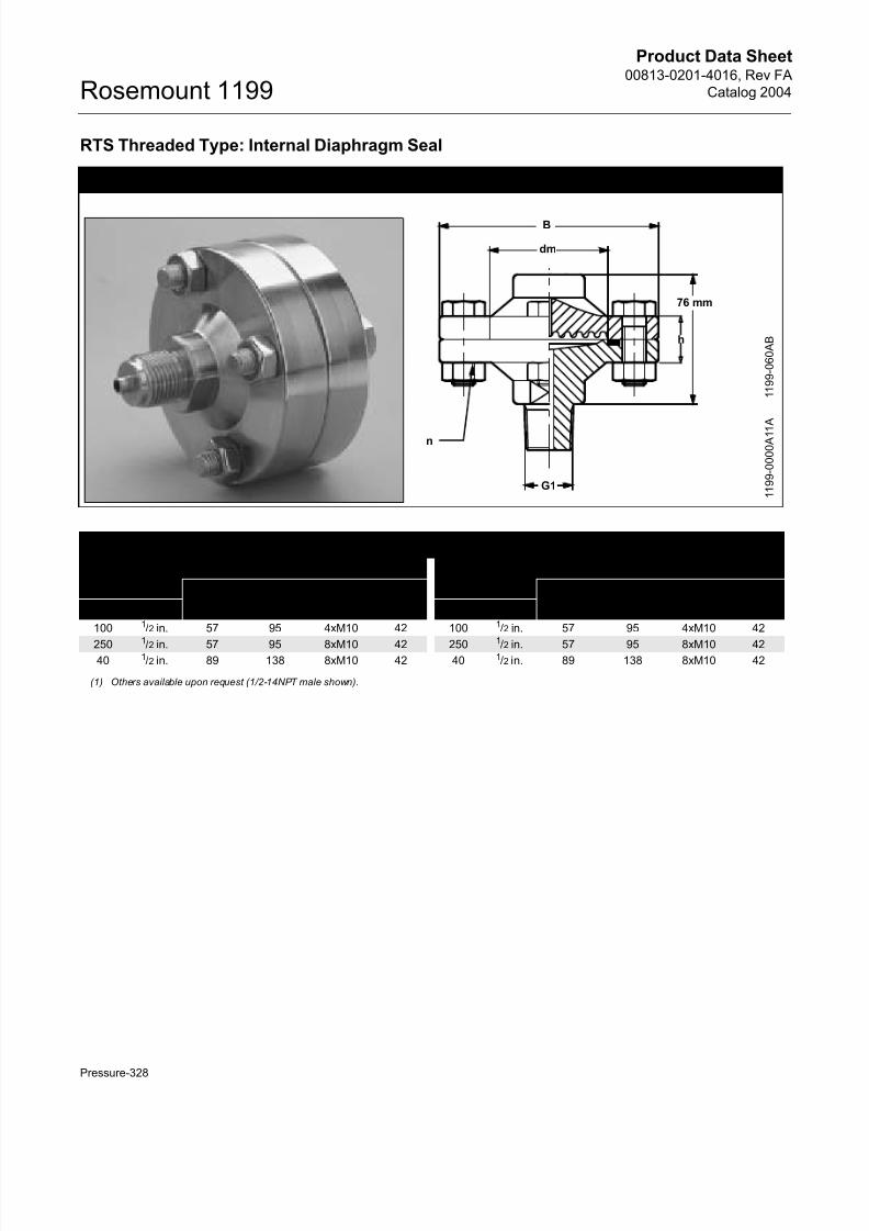
RTS Threaded Type: Internal Diaphragm Seal
Dimensional Drawing for RTS Threaded Type: Internal Diaphragm Seal
h
dm
G1
B
n
1 1 9 9 - 0 0 0 0 A 1 1
A
1 1 9 9 - 0 6 0 A B
76 mm
RTS Threaded Process Connection Dimensions
Parallel Thread Tapered Thread
Dimensions (mm) Dimensions (mm)
PN G1(1) dm B n h PN G1(1) dm B n h
100 1/2 in. 57 95 4xM10 42 100 1/2 in. 57 95 4xM10 42
2501
/2 in. 57 95 8xM10 42 2501
/2 in. 57 95 8xM10 4240 1/2 in. 89 138 8xM10 42 40 1/2 in. 89 138 8xM10 42
(1) Others available upon request (1/2-14NPT male shown).
Page 27
8/13/2019 4016_RevFA_catalog2004
http://slidepdf.com/reader/full/4016revfacatalog2004 27/56
Product Data Sheet00813-0201-4016, Rev FA
Catalog 2004
Pressure-329
Rosemount 1199
TABLE 17. RTS Threaded Type: Internal Diaphragm Seal — Ordering Information(1)
Code Process Connection Style
DRTS Threaded (Standard thread is male; for female, see options below)
Code(2) Process Connection Size
C Parallel thread: G1/2 A DIN 16288
Code Pressure Rating Diaphragm Size
1 PN 100 57 mm
2 PN 250 57 mm
4 PN 40 89 mm
Code(3) Diaphragm Material Upper Housing Material
LA 316L SST 316 SST
LB Hastelloy C-276 316 SST
LC Tantalum 316 SST
WW 316Ti SST (WNr 1.4571) 316 SST (WNr 1.4571)
LE Inconel 60 316 SST
LJ Hastelloy B 316 SST
LP Nickel 201 316 SST
L4 Hastelloy C-22 316 SST
LV Monel 400 316 SST
WC Tantalum 316 SST (WNr 1.4571)
WB Hastelloy C-276 316 SST (WNr 1.4571)
EM Titanium Gr.2 Titanium Gr.2
Code Lower Housing Material (Supplied with Viton Gasket)(4)
L 316L SST
W 316Ti SST (WNr 1.4571)
B Hastelloy C-276
Code Flushing Options
1 One ¼–18NPT Flushing Connection
3 Two ¼–18 NPT Flushing Connection5 No Flushing Connection
Code Options (Multiple Selections)
0 None
V Teflon Coated Diaphragm for non-stick purposes only (available with 316L SST and Hastelloy C–276 diaphragm only)
J Teflon Gasket
2 98% Graphite Gasket for chloride applications
Z Material Traceability per EN10204 DIN 3.1B (Requires selection of transmitter Code Q8)
5 50 !m Diaphragm Thickness (available in 316L SST or Hastelloy )
8 150 !m Diaphragm Thickness - 316L SST or Hastelloy C-276 Diaphragm Material only
9 Female Threads (Internal parallel thread G1/2 A–DIN 16288, internal tapered thread R1/2 –ISO 7/1)
H SST Drain/Vent for flushing connection(s)
G SST Plug(s) for flushing connection(s)
B Extra Fill for Cold Temperature ApplicationsD Hastelloy Plugs for Flushing Connections
T NACE MR–01–75
(1) Shaded areas indicate special orders. Consult your Rosemount representative for availability, performance effects, and lead time.
(2) For special process connection sizes, contact your Rosemount representative.
(3) When ordering special diaphragm materials, the standard housing material is 316L SST unless noted otherwise.
(4) Limited to a process temperature of 200 °C.
Page 28
8/13/2019 4016_RevFA_catalog2004
http://slidepdf.com/reader/full/4016revfacatalog2004 28/56
Product Data Sheet00813-0201-4016, Rev FA
Catalog 2004Rosemount 1199
Pressure-330
TABLE 18. RTS Threaded Type: Internal Diaphragm Seal — Ordering Information(1)
Code Process Connection Style
ARTS Tapered Threaded (Standard thread is female, for male, see options below)
Code(2)
Process Connection Size3 1/2 –14 NPT
5 1–14 NPT
Code Pressure Rating Diaphragm Size
1 PN 100 57 mm
2 PN 250 57 mm
4 PN 40 89 mm
Code(3) Diaphragm Material Upper Housing Material
LA 316L SST 316 SST
LB Hastelloy C-276 316 SST
LC Tantalum 316 SST
WW 316Ti SST (WNr 1.4571) 316 SST (WNr 1.4571)
LE Inconel 60 316 SST
LJ Hastelloy B 316 SSTLP Nickel 201 316 SST
L4 Hastelloy C-22 316 SST
LV Monel 400 316 SST
WC Tantalum 316 SST (WNr 1.4571)
WB Hastelloy C-276 316 SST (WNr 1.4571)
EM Titanium Gr.2 Titanium Gr.2
Code Lower Housing Material (Supplied with Viton Gasket)(4)
L 316L SST
W 316Ti SST (WNr 1.4571)
B Hastelloy C-276
P(5) PVDF
Code Flushing Options
1 One ¼–18NPT Flushing Connection3 Two ¼–18 NPT Flushing Connection
5 No Flushing Connection
Code Options (Multiple Selections)
0 None
V Teflon Coated Diaphragm for non-stick purposes only (available with 316L SST and Hastelloy C–276 diaphragm only)
J Teflon Gasket
2 98% Graphite Gasket for chloride applications
Z Material Traceability per EN10204 DIN 3.1B (Requires selection of transmitter Code Q8)
5 50 !m Diaphragm Thickness (available in 316L SST or Hastelloy )
8 150 !m Diaphragm Thickness - 316L SST or Hastelloy C-276 Diaphragm Material only
1 NPT Male Threads
H SST Drain/Vent for flushing connection(s)
G SST Plug(s) for flushing connection(s)B Extra Fill for Cold Temperature Applications
D Hastelloy Plugs for Flushing Connections
T NACE MR–01–75
(1) Shaded areas indicate special orders. Consult your Rosemount representative for availability, performance effects, and lead time.
(2) For special process connection sizes, contact your local Rosemount representative.
(3) When ordering special diaphragm materials, the standard housing material is 316L SST unless noted otherwise.
(4) Limited to a process temperature of 200 °C.
(5) Pressure rating reduced. Contact your Rosemount representative for details.
Page 29
8/13/2019 4016_RevFA_catalog2004
http://slidepdf.com/reader/full/4016revfacatalog2004 29/56
Product Data Sheet00813-0201-4016, Rev FA
Catalog 2004
Pressure-331
Rosemount 1199
HTS Threaded Type: Flush Diaphragm Seal
Dimensional Drawing for HTS Threaded Type: Flush Diaphragm Seal
HTS Process Connection Dimensions
ISO 228/1 Parallel Thread NPT: Tapered Thread
G1 PN
Dimensions (mm)
G1 PN
Dimensions (mm)
dm L b d dm L b d
1 in. 600 25 21 30 47 1 in. 600 25 23 30 47
1½ in. 600 32 30 30 60 1½ in. 600 32 32 30 60
2 in. 600 40 35 30 70 2 in. 600 40 37 30 70
1 1 9 9 - 0 0 0 0 A 0 5 A
L
b
dm
G1
d
1 1 9 9 - 0 7 3 A B
Page 30
8/13/2019 4016_RevFA_catalog2004
http://slidepdf.com/reader/full/4016revfacatalog2004 30/56
Product Data Sheet00813-0201-4016, Rev FA
Catalog 2004Rosemount 1199
Pressure-332
TABLE 19. HTS Threaded Type: Flush Diaphragm Seal — DIN Ordering Information(1)
Code Process Connection Style
DHTS(2) Parallel Thread
Code Process Connection Size Diaphragm Diameter
E G1 25 mm
G G11/2 32 mm
J G2 40 mm
Code Pressure Rating
6 600 bar
Code Diaphragm and Wetted Parts Material Housing Material
LA00 316L SST 316 SST
WW00 316Ti SST (WNr 1.4571) 316 SST (WNr 1.4571)
Code Options (Multiple Selections)
0 None
Z Material Traceability per EN10204 DIN 3.1B (Requires selection of transmitter Code Q8)
5 50 !m Diaphragm Thickness (available in 316L SST or Hastelloy C-276)
8 150 !m Diaphragm Thickness - 316L SST or Hastelloy C-276 Diaphragm Material only
B Extra Fill for Cold Temperature Applications
T NACE MR–01–75
(1) Consult your Rosemount representative for use with low calibrated spans. Shaded areas indicate special orders, consult your Rosemount representativefor availability, performance effects, and lead time.
(2) Gasket available upon request; contact your Rosemount representative.
TABLE 20. HTS Threaded Type: Flush Diaphragm Seal —NPT Ordering Information (1)
Code Process Connection Style
AHTS Tapered Thread
Code Process Connection Size Diaphragm Diameter
5 1-11,5 NPT 25 mm
7 1½-11,5 NPT 32 mm
9 2-11,5 NPT 40 mm
Code Pressure Rating
6 600 bar
Code Diaphragm and Wetted Parts Material Housing Material
LA00 316L SST 316L SST
WW00 316Ti SST (WNr 1.4571) 316Ti SST (WNr 1.4571)
Code Options (Multiple Selections)
0 None
Z Material Traceability per EN10204 DIN 3.1B (Requires selection of transmitter Code Q8)
5 50 !m Diaphragm Thickness (available in 316L SST or Hastelloy C-276)
8 150 !m Diaphragm Thickness - 316L SST or Hastelloy C-276 Diaphragm Material only
B Extra Fill for Cold Temperature Applications
T NACE MR–01–75
(1) Consult your Rosemount representative for use with low calibrated spans. Shaded areas indicate special orders, consult your Rosemount representativefor availability, performance effects, and lead time.
Page 31
8/13/2019 4016_RevFA_catalog2004
http://slidepdf.com/reader/full/4016revfacatalog2004 31/56
Product Data Sheet00813-0201-4016, Rev FA
Catalog 2004
Pressure-333
Rosemount 1199
TFS Cell Type: In-Line Diaphragm Seal
Dimensional Drawings for TFS Cell Type: In-Line Diaphragm Seal
L D
DN
1 1 9 9 - 0 0 0 A 0 1 2 A , R W
I B 0 1 A
1 1 9 9 - 0 0 7 4 A B
TFS Process Connection Dimensions
DIN 2501 ANSI/ASME B16.5
Process
Connection
Size PN
Dimensions (mm) Process
Connection
Size CL
Dimensions (mm)
DN D L DN D L
25 16-400 27, 7 68 90 1 in. 150-2500 27,7 51 90
40 16-400 41,0 88 90 1½ in. 150-2500 41,0 73 90
50 16-400 50 102 90 2 in. 150-2500 52,6 92 90
80 16-400 82 138 90 3 in. 150-2500 78,0 127 90
100 16-400 101 162 90 4 in. 150-2500 101 157 90
Page 32
8/13/2019 4016_RevFA_catalog2004
http://slidepdf.com/reader/full/4016revfacatalog2004 32/56
Product Data Sheet00813-0201-4016, Rev FA
Catalog 2004Rosemount 1199
Pressure-334
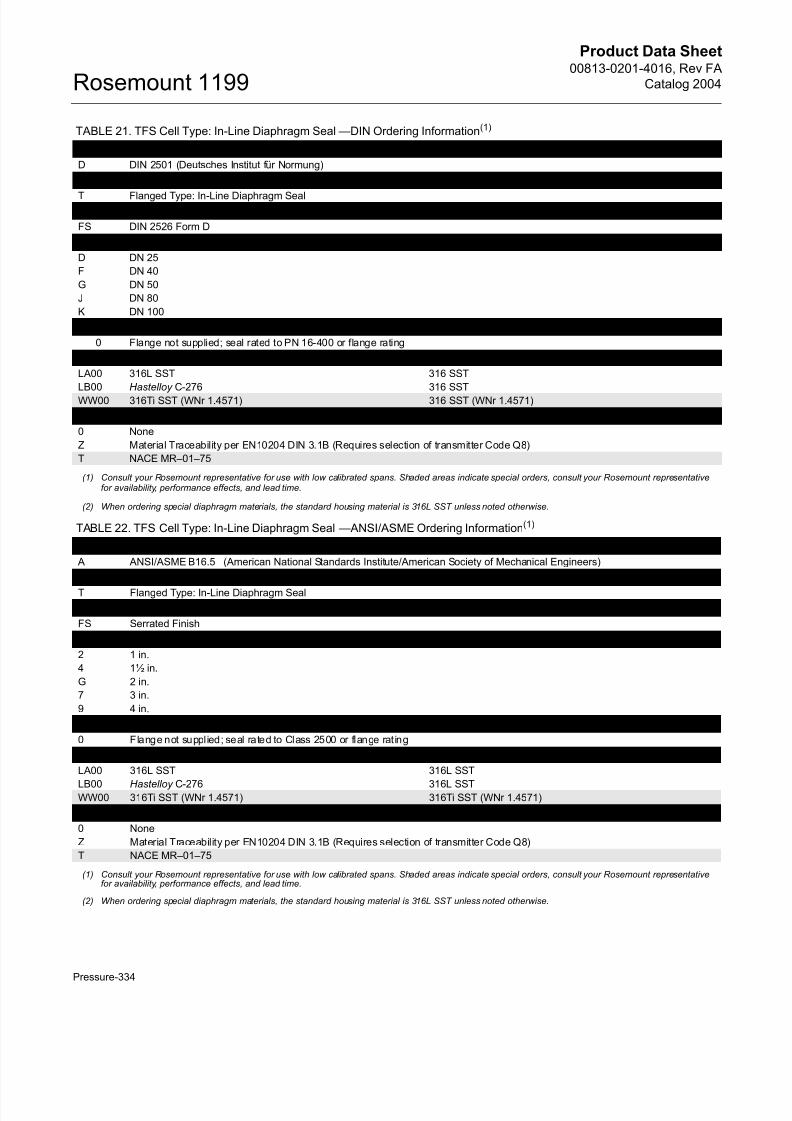
TABLE 21. TFS Cell Type: In-Line Diaphragm Seal —DIN Ordering Information(1)
Code Industry Standard
D DIN 2501 (Deutsches Institut für Normung)
Code Process Connection Style
T Flanged Type: In-Line Diaphragm SealCode Gasket Surface
FS DIN 2526 Form D
Code Process Connection Size
D DN 25
F DN 40
G DN 50
J DN 80
K DN 100
Code Pressure Rating
0 Flange not supplied; seal rated to PN 16-400 or flange rating
Code Diaphragm and Wetted Parts Material(2) Housing Material
LA00 316L SST 316 SST
LB00 Hastelloy C-276 316 SST
WW00 316Ti SST (WNr 1.4571) 316 SST (WNr 1.4571)
Code Options (Multiple Selections)
0 None
Z Material Traceability per EN10204 DIN 3.1B (Requires selection of transmitter Code Q8)
T NACE MR–01–75
(1) Consult your Rosemount representative for use with low calibrated spans. Shaded areas indicate special orders, consult your Rosemount representativefor availability, performance effects, and lead time.
(2) When ordering special diaphragm materials, the standard housing material is 316L SST unless noted otherwise.
TABLE 22. TFS Cell Type: In-Line Diaphragm Seal —ANSI/ASME Ordering Information(1)
Code Industry Standard
A ANSI/ASME B16.5 (American National Standards Institute/American Society of Mechanical Engineers)
Code Process Connection Style
T Flanged Type: In-Line Diaphragm Seal
Code Gasket Surface
FS Serrated Finish
Code Process Connection Size
2 1 in.
4 1½ in.
G 2 in.
7 3 in.
9 4 in.
Code Pressure Rating
0 Flange not supplied; seal rated to Class 2500 or flange rat ing
Code Diaphragm and Wetted Parts Material(2) Housing Material
LA00 316L SST 316L SST
LB00 Hastelloy C-276 316L SSTWW00 316Ti SST (WNr 1.4571) 316Ti SST (WNr 1.4571)
Code Options (Multiple Selections)
0 None
Z Material Traceability per EN10204 DIN 3.1B (Requires selection of transmitter Code Q8)
T NACE MR–01–75
(1) Consult your Rosemount representative for use with low calibrated spans. Shaded areas indicate special orders, consult your Rosemount representativefor availability, performance effects, and lead time.
(2) When ordering special diaphragm materials, the standard housing material is 316L SST unless noted otherwise.
Page 33
8/13/2019 4016_RevFA_catalog2004
http://slidepdf.com/reader/full/4016revfacatalog2004 33/56
Product Data Sheet00813-0201-4016, Rev FA
Catalog 2004
Pressure-335
Rosemount 1199
Flow-Thru Flanged
Flow-Thru Flange Seal Dimensional Drawing
A
B
2.000
(50.8)2.400
(60.96)
Class
(lb.)
Nominal
Pipe Size
(in.)
Overall Length
± 0.05
A
Upper to Centerline
Height
B
150 1 7.00 (177.8) 2.28 (57.91)
2 9.00 (228.6) 2.80 (71.12)
3 11.00 (279.4) 3.50 (88.9) 1 1 9 9 - C 1 9 5 0 0 4 C 1 ,
C 1 9 5 0 0 4 C 2
NOTEDimensions are in inches (millimeters)
TABLE 23. Flow-Thru Flanged Seal Ordering Information
Code Industry Standard A ANSI/ASME B16.5 (American National Standards Institute/American Society of Mechanical Engineers)
Code Process Connection Style
WFW Flow-Thru Flanged
Code Process Connection Size(1)
2 1 in.
G 2 in.
7 3 in.
Code Flange Pressure Rating (1)
1 Class 150
Code Upper Housing Diaphragm Material(1)
LA 316 SST 316L SST
Code Lower Housing(1)
L 316 SSTCode Pipe Schedule(1) Maximum Working Pressure of Pipe
1 in. 2 in. 3 in.
N 40/40s 1500 1500 1500
Code Options
0 None
3 304 SST Bolts
J Teflon (PTFE) O-ring (between Upper and Lower Housing)
N Grafoil Gasket (between Upper and Lower Housing)
K Gylon Gasket (between Upper and Lower Housing)
B Cold temperature application (ambient less than -20° C)
(1) Consult factory for special process connection sizes, flange pressure ratings, diaphragm/lower housing materials, and pipe schedules.
Page 34
8/13/2019 4016_RevFA_catalog2004
http://slidepdf.com/reader/full/4016revfacatalog2004 34/56
Product Data Sheet00813-0201-4016, Rev FA
Catalog 2004Rosemount 1199
Pressure-336
Flow-Thru Socket and Butt Weld Seals
Flow–Thru Socket Weld
Overall Length
Upper to Centerline
Height Bore Diameter
Counter Bore
Diameter Counter Bore Depth Overall Height
Code A B C D E F
A 3.50 (88.9) 2.18 (55.37) 0.82 (20.83) 1.06 (26.92) 0.40 (10.16) 3.09 (78.49)
2 3.50 (88.9) 2.28 (57.91) 1.05 (26.67) 1.32 (33.53) 0.40 (10.16) 3.33 (84.58)
4 4.00 (101.6) 2.56 (65.02) 1.61 (40.89) 1.91 (48.51) 0.50 (12.7) 3.90 (99.06)
G 4.00 (101.6) 2.80 (71.12) 2.07 (52.58) 2.38 (60.45) 0.50 (12.7) 4.37 (111.0)
Flow–Thru Butt Weld
Overall
Length
Upper to Centerline
Height
Bore
Diameter
Counter Bore
Diameter Overall Height
Code A B C D F
A 4.25 (107.95) 2.17 (55.12) 0.82 (20.83) 1.05 (26.67) 3.13 (79.5)
2 4.25 (107.95) 2.29 (58.17) 1.05 (26.67) 1.32 (33.53) 3.39 (86.11)
4 5.00 (127.0) 2.57 (65.28) 1.61 (40.89) 1.90 (48.26) 3.95 (100.33)
G 5.00 (127.0) 2.77 (70.36) 2.07 (52.58) 2.38 (60.45) 4.38 (111.25)
F
B
CD
2.01 (51.1)
2.40 (60.96A
3.50 (88.9)
E
1 1 9 9 - C
1 9 5 0 0 7 A , C 1 9 5 0 0 7 B ,
C 1 9 5 0
0 8 A , C 1 9 5 0 0 8 B
3.50 (88.9)
2.01(51.05)2.40
(60.96)A
B
C D
F
1 in. Flow–Thru Butt Weld Seal
NOTEDimensions are in inches (millimeters)
Page 35
8/13/2019 4016_RevFA_catalog2004
http://slidepdf.com/reader/full/4016revfacatalog2004 35/56
Product Data Sheet00813-0201-4016, Rev FA
Catalog 2004
Pressure-337
Rosemount 1199
TABLE 24. Flow-Thru Socket and Butt Weld Seals Ordering Information
Code Industry Standard
A ANSI/ASME B16.5 (American National Standards Institute/American Society of Mechanical Engineers)
Code Process Connection Style
WWW Flow-Thru Socket Weld
WBW Flow-Thru Butt Weld
Code Process Connection Size(1)
A ¾ in.
2 1 in.
4 1 ½ in.
G 2 in.
Code Pressure Rating
1 Not Applicable (See Pipe Schedule)
Code Upper Housing Diaphragm Material(1)
LA 316 SST 316L SST
Code Lower Housing(1)
L 316 SST
Code Pipe Schedule(1) Maximum Working Pressure of Pipe
¾ in. 1 in. 1 ½ in. 2 in.
N 40/40s 1500 1500 1500 1500
Code Options
0 None
3 304 SST Bolts
J Teflon (PTFE) O-ring (between Upper and Lower Housing)
N Grafoil Gasket (between Upper and Lower Housing)
K Gylon Gasket (between Upper and Lower Housing)
B Cold Temperature application (ambient less than -20° C)
(1) Consult factory for special process connection sizes, diaphragm/lower housing materials, and pipe schedules.
Page 36
8/13/2019 4016_RevFA_catalog2004
http://slidepdf.com/reader/full/4016revfacatalog2004 36/56
Product Data Sheet00813-0201-4016, Rev FA
Catalog 2004Rosemount 1199
Pressure-338
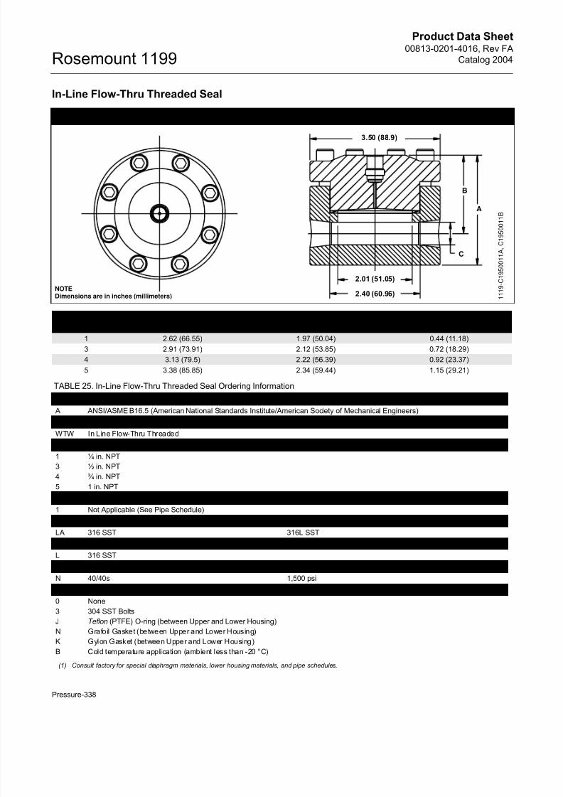
In-Line Flow-Thru Threaded Seal
Flow-Thru Threaded Seal Dimensional Drawings
Code
Overall Length
A
Upper to Centerline Height
B
Bore Diameter
C
1 2.62 (66.55) 1.97 (50.04) 0.44 (11.18)
3 2.91 (73.91) 2.12 (53.85) 0.72 (18.29)
4 3.13 (79.5) 2.22 (56.39) 0.92 (23.37)
5 3.38 (85.85) 2.34 (59.44) 1.15 (29.21)
TABLE 25. In-Line Flow-Thru Threaded Seal Ordering Information
Code Industry Standard
A ANSI/ASME B16.5 (American National Standards Institute/American Society of Mechanical Engineers)
Code Process Connection Style
WTW In Line Flow-Thru Threaded
Code Process Connection Size
1 ¼ in. NPT
3 ½ in. NPT
4 ¾ in. NPT
5 1 in. NPT
Code Pressure Rating
1 Not Applicable (See Pipe Schedule)
Code Upper Housing Diaphragm Material(1)
LA 316 SST 316L SST
Code Lower Housing(1)
L 316 SSTCode Pipe Schedule(1) Maximum Working of Pressure Pipe
N 40/40s 1,500 psi
Code Options
0 None
3 304 SST Bolts
J Teflon (PTFE) O-ring (between Upper and Lower Housing)
N Grafoil Gasket (between Upper and Lower Housing)
K Gylon Gasket (between Upper and Lower Housing)
B Cold temperature application (ambient less than -20 °C)
(1) Consult factory for special diaphragm materials, lower housing materials, and pipe schedules.
NOTEDimensions are in inches (millimeters)
A
B
C
3.50 (88.9)
2.01 (51.05)
2.40 (60.96) 1 1 1 9 - C 1 9 5 0 0 1 1 A , C 1 9 5 0 0 1 1 B
Page 37
8/13/2019 4016_RevFA_catalog2004
http://slidepdf.com/reader/full/4016revfacatalog2004 37/56
Product Data Sheet00813-0201-4016, Rev FA
Catalog 2004
Pressure-339
Rosemount 1199
JES Extruder Flanged Type
Dimensional Drawings for JES Extruder Flanged Type
13.4
35
RL
d
5
d2
K
D
1 1 9 9 - 1 1 9 9 0 0 4 B , 1 1 9 9 - N C E S A 0 1 C
JES Process Connection Dimensions (mm)
Flange ThicknessPN dM D K d2 RL
400 bar 23 85 54 4x14 See Table 26 25 mm
TABLE 26. JES Extruder Flanged Type — Ordering Information(1)
Code Process Connection Style
NJES Plastics Extrusion Clamping Flange
Code Process Connection Size
B 23 mm
Code Pressure Rating
P(2) 400 bar
Code Diaphragm and Wetted Parts Material Upper Housing Material
LA 316L SST 316 SST
WW 316Ti SST (WNr 1.4571) 316 SST (WNr 1.4571)Code Extension Length Code Extension Length
0 Add 0 mm 5 Add 50 mm
1 Add 10 mm 6 Add 60 mm
2 Add 20 mm 7 Add 70 mm
3 Add 30 mm 8 Add 80 mm
4 Add 40 mm 9 Add 90 mm
Code Extension Length (Amount to Add) Code Extension Length (Amount to Add)
0 Add 0 mm 5 Add 5 mm
1 Add 1 mm 6 Add 6 mm
2 Add 2 mm 7 Add 7 mm
3 Add 3 mm 8 Add 8 mm
4 Add 4 mm 9 Add 9 mm
Code Options (Multiple Selections)
0 None
5 50 !m Diaphragm Thickness
6 Add 100 mm extension length
7 Add 200 mm extension length
Z Material Traceability per EN10204 DIN 3.1B (Requires selection of transmitter Code Q8)
T NACE MR–01–75
(1) Shaded areas indicate special orders. Consult your Rosemount representative for availability, performance effects, and lead time.
(2) Minimum span is 60 bar.
Page 38
8/13/2019 4016_RevFA_catalog2004
http://slidepdf.com/reader/full/4016revfacatalog2004 38/56
Product Data Sheet00813-0201-4016, Rev FA
Catalog 2004Rosemount 1199
Pressure-340
Sanitary Diaphragm Seal Systems
VLS and VMS Sanitary In-Line Diaphragm Seals—
DIN 11851 or SMS Process Connections
Dimensional Drawing for VLS and VMS Sanitary In-Line Diaphragm Seals
G1DN
1 1 9 9 - R W I C 0 1 A , 1 1 9 9 - 0 7 5 A B
L
VLS and VMS Process Connection Dimensions(1)
DIN 11851(1) SMS
Process
Connection
Size PN
Dimensions (mm) Process
Connection
Size PN
Dimensions (mm)
DN G1 L DN G1 L
25 40 24,9 Rd52x1/6 90 25 40 24,9 Rd40x1/6 90
40 40 38,1 Rd65x1/6 90 38 40 38,1 Rd60x1/6 90
50 40 50 Rd78x1/6 90 51 40 50 Rd70x1/6 90
80 40 81,0 Rd110x1/4 90 76 40 76,0 Rd98x1/6 90
100 40 101 Rd130x1/4 90
(1) RJT and IDF dimensions available upon request.
Page 39
8/13/2019 4016_RevFA_catalog2004
http://slidepdf.com/reader/full/4016revfacatalog2004 39/56
Product Data Sheet00813-0201-4016, Rev FA
Catalog 2004
Pressure-341
Rosemount 1199
TABLE 27. VLS Sanitary In-Line Diaphragm Seal—DIN Ordering Information(1)
Code Industry Standard
S Sanitary
Code Process Connection Style(2)
VLS Sanitary In Line Seal per DIN 11851 (maximum working pressure: 40 bar)
Code Process Connection Size
D0 DN 25
F0 DN 40
G0 DN 50
J0 DN 80
K0 DN 100
Code Diaphragm Material
LA00 316L SST
WW00 316Ti SST (WNr 1.4571)
Code Options (Multiple Selections)
0 None
6 Electrolytical polishing of diaphragm material
Z Material Traceability per EN10204 DIN 3.1B (Requires selection of transmitter code Q8)
(1) Consult your Rosemount representative for use with low calibrated spans. Shaded areas indicate special orders, consult your Rosemount representativefor availability, performance effects, and lead time.
(2) Other industry standards such as IDF and RJT available upon request.
TABLE 28. VMS Sanitary In-Line Diaphragm Seal—SMS Ordering Information(1)
Code Industry Standard
S Sanitary
Code Process Connection Style(2)
VMS Sanitary In Line Seal per SMS (maximum working pressure: 40 bar)Code Process Connection Size
20 DN 25
30 DN 38
50 DN 51
70 DN 76
Code Diaphragm Material
LA00 316L SST
WW00 316Ti SST (WNr 1.4571)
Code Options (Multiple Selections)
0 None
6 Electrolytical polishing of diaphragm material
Z Material Traceability per EN10204 DIN 3.1B (Requires selection of transmitter code Q8)
(1) Consult your Rosemount representative for use with low calibrated spans. Shaded areas indicate special orders, consult your Rosemount representativefor availability, performance effects, and lead time.
(2) Other industry standards such as IDF and RJT available upon request.
Page 40
8/13/2019 4016_RevFA_catalog2004
http://slidepdf.com/reader/full/4016revfacatalog2004 40/56
Product Data Sheet00813-0201-4016, Rev FA
Catalog 2004Rosemount 1199
Pressure-342
SLS, SMS, SFS and SRS Sanitary Seals: Dairy Process Connections—Female Thread
Dimension Drawing for SLS, SMS, SFS and SRS:Dairy Process Connections—Female Thread
dm
G1
A
D
b
1 1 9 9 - 0 0 0 0 B 0 7 A ,
SLS, SMS, SFS and SRS Process Connection Dimensions
Female Thread
STANDARD
DIMENSIONS (mm)
DN PN A b dm G1 D
DIN 11851 25 40 21 45 25 Rd521/6 63
32 40 21 40 32 Rd581/6 70
40 40 21 45 40 Rd651/6 78
50 40 22 46 50 Rd781/6 92
65 40 25 47 57 Rd951/6 112
80 40 30 47 72 Rd1101/4 127
SMS 25 40 20 38 25 Rd401/6 51
32 40 22 40 32 Rd481/6 60
38 40 25 40 32 Rd601/6 74
51 40 26 40 50 Rd701/6 84
63,5 40 30 40 57 Rd851/6 100
76 40 32 40 72 Rd981/6 114
IDF(1)
RJT(1)
(1) Contact factory for dimensions.
Page 41
8/13/2019 4016_RevFA_catalog2004
http://slidepdf.com/reader/full/4016revfacatalog2004 41/56
Product Data Sheet00813-0201-4016, Rev FA
Catalog 2004
Pressure-343
Rosemount 1199
TABLE 29. SLS Sanitary Seals: Dairy Process Connection—Female Thread Ordering Information(1)
Code Industry Standard
S Sanitary
Code Process Connection Style
SLS Female Thread per DIN 11851
Code Process Connection Size Pressure Rating(2)
D0 DN 25 40 bar
F0 DN 40 40 bar
G0 DN 50 40 bar
J0 DN 80 40 bar
E0 DN 32 40 bar
H0 DN 65 40 bar
Code Diaphragm Material
LA00 316L SST
WW00 316Ti SST (WNr 1.4571)
Code Options (Multiple Selections)
0 None
6 Electrolytical polishing of diaphragm material
Z Material Traceability per EN10204 DIN 3.1B (Requires selection of transmitter code Q8)
2 Counterpiece (tank/pipe spud) and Gasket (ethylene propylene standard gasket material)
(1) Shaded areas indicate special orders. Consult your Rosemount representative for availability, performance effects, and lea d time.
(2) Maximum working pressure is dependent on the pressure rating of the connection.
TABLE 30. SMS, SFS and SRS Sanitary Seals: Dairy Process Connection—Female Thread Ordering Information(1)
Code Industry Standard
S Sanitary
Code Process Connection Style
SMS Female Thread per SMS Standard
SFS Female Thread per IDF Standard
SRS Female Thread per RJT Standard
Code Process Connection Size Pressure Rating(2)
30 DN 38 (11/2 in.) 40 bar
50 DN 51 (2 in.) 40 bar
20 DN 25 40 bar
60 DN 63.5 40 bar
70 DN 76 40 bar
Code Diaphragm Material
LA00 316L SST
WW00 316Ti SST (WNr 1.4571)
Code Options (Multiple Selections)
0 None
6 Electrolytical polishing of diaphragm material
Z Material Traceability per EN10204 DIN 3.1B (Requires selection of transmitter code Q8)
2 Counterpiece (tank/pipe spud) and Gasket (ethylene propylene standard gasket material)
(1) Shaded areas indicate special orders. Consult your Rosemount representative for availability, performance effects, and lea d time.
(2) Maximum working pressure is dependent on the pressure rating of the connection.
Page 42
8/13/2019 4016_RevFA_catalog2004
http://slidepdf.com/reader/full/4016revfacatalog2004 42/56
Product Data Sheet00813-0201-4016, Rev FA
Catalog 2004Rosemount 1199
Pressure-344
MLS, MMS, MFS and MRS Sanitary Seal: Dairy Process Connections—Male Thread
Dimensional Drawing for MLS, MMS, MFS and MRS:Dairy Process Connections—Male Thread
G1
dm
b
1 1 9 9 - 0 5 7
1 1 9 9 - 0 0 0 0 A 0 7
MLS, MMS, MFS and MRS Process Connection Dimensions
STANDARD
Male Thread
DN PN
DIMENSIONS (mm)
b dm G1
DIN 11851 25 40 46 25 Rd521/6
32 40 47 32 Rd581/6
40 40 46 32 Rd651/6
50 40 46 40 Rd781/6
65 40 46 57 Rd951/6
80 40 47 72 Rd1101/4
SMS 25 40 47 25 Rd401/6
32 40 47 32 Rd481/6
38 40 47 32 Rd601/6
51 40 47 40 Rd701/6
63,5 40 47 57 Rd851/6
76 40 47 72 Rd981/6
IDF(1)
RJT(1)
(1) Consult the factory for dimensions.
Page 43
8/13/2019 4016_RevFA_catalog2004
http://slidepdf.com/reader/full/4016revfacatalog2004 43/56
Product Data Sheet00813-0201-4016, Rev FA
Catalog 2004
Pressure-345
Rosemount 1199
TABLE 31. MLS Sanitary Seal: Dairy Process Connections—Male Thread Ordering Information(1)
Code Industry Standard
S Sanitary
Code Process Connection Style
MLS Male Thread per DIN 11851
Code Process Connection Size Pressure Rating(2)
F0 DN 40 40 bar
G0 DN 50 40 bar
J0 DN 80 40 bar
D0 DN 25 40 bar
E0 DN 32 40 bar
H0 DN 65 40 bar
Code Diaphragm Material
LA00 316L SST
WW00 316 Ti SST (WNr 1.4571)
Code Options (Multiple Selections)
0 None
6 Electrolytical polishing of diaphragm material
Z Material Traceability per EN10204 DIN 3.1B (Requires selection of transmitter code Q8)
2 Counterpiece (tank/pipe spud) and gasket (standard gasket material ethylene propylene)
(1) Shaded areas indicate special orders. Consult your Rosemount representative for availability, performance effects, and lea d time.
(2) Maximum working pressure is dependent on the pressure rating of the connection.
TABLE 32. MMS, MFS, and MRS Sanitary Seals: Dairy Process Connections—Male Thread Ordering Information(1)
Code Industry Standard
S Sanitary
Code Process Connection Style
MMS Male Thread per SMS Standard
MFS Male Thread per IDF Standard
MRS Male Thread per RJT Standard
Code Process Connection Size Pressure Rating(2)
30 DN 38 (11/2 in.) 40 bar
50 DN 51 (2 in.) 40 bar
20 DN 25 40 bar
60 DN 63.5 40 bar
70 DN 76 40 bar
Code Diaphragm Material and Wetted Parts
LA00 316L SST
WW00 316Ti SST (1.4571 WNr)
Code Options (Multiple Selections)
0 None
6 Electrolytical polishing of diaphragm material
Z Material Traceability per EN10204 DIN 3.1B (Requires selection of transmitter code Q8)
2 Counterpiece (tank/pipe spud) and gasket (standard gasket material ethylene propylene)
(1) Shaded areas indicate special orders. Consult your Rosemount representative for availability, performance effects, and lea d time.
(2) Maximum working pressure is dependent upon the pressure rating of the connection.
Page 44
8/13/2019 4016_RevFA_catalog2004
http://slidepdf.com/reader/full/4016revfacatalog2004 44/56
Product Data Sheet00813-0201-4016, Rev FA
Catalog 2004Rosemount 1199
Pressure-346
VCS Sanitary In-Line Diaphragm Seal—Tri-Clamp Process Connection
Dimensional Drawing for VCS Sanitary In-Line Diaphragm Seal
VCS Process Connection Dimensions
Max. Working Pressure DN
Dimensions (mm)
Od OD A
40 bar 1 in. 22,1 50,4 58
40 bar 1 1/2 in. 34,8 50,4 58
40 bar 2 in. 47,5 63,9 78,5
40 bar 2 1/2 in. 60,20 77,4 85,940 bar 3 in. 72,9 90,9 99
40 bar 4 in. 97 118,9 129
TABLE 33. VCS Sanitary In-Line Diaphragm Seal Ordering Information(1)
(1) Consult a Rosemount representative for minimum calibrated spans. Shaded areas indicate special orders, consult your Rosemount representative foravailability, performance effects, and lead time.
Code Industry Standard
S Sanitary
Code Process Connection Style
VCS(2)
(2) Gasket and clamp are furnished by the user. The maximum working pressure is dependent upon the pressure rating of the connection.
In Line Tri-Clamp Seal (Maximum Working Pressure: 40 bar)
Code(3)
(3) DIN Tri-Clamp dimensions available on request.
Process Connection Size
20 1 in.
30 1½ in.
50 2 in.
70 3 in.
90 4 in.
Code Diaphragm Material
LA00 316L SST
WW00 316Ti SST (WNr 1.4571)
Options (Multiple Selections)
0 None
Z Material Traceability per EN10204 DIN 3.1B (Requires selection of transmitter code Q8)
C 2 0 2 4 0 A
Od
OD
38,1
90
D
Page 45
8/13/2019 4016_RevFA_catalog2004
http://slidepdf.com/reader/full/4016revfacatalog2004 45/56
Product Data Sheet00813-0201-4016, Rev FA
Catalog 2004
Pressure-347
Rosemount 1199
SCS Sanitary Tri-Clamp ® Diaphragm Seal
Dimensional Drawing for SCS Sanitary Tri-Clamp Diaphragm Seal
SCS Process Connection Dimensions
DN PN
Dimensions (mm)
dM D
1½ in. 40 32 50,4
2 in. 40 40 63,9
2½ in. 40 57 50,4
3 in. 40 72 90,9
TABLE 34. SCS Sanitary Tri-Clamp Diaphragm Seal Ordering Information(1)
(1) Consult a Rosemount representative for minimum calibrated spans. Shaded areas indicate special orders, consult your Rosemount representative foravailability, performance effects, and lead time.
Code Industry Standard
S Sanitary
Code Process Connection Style
SCS(2)
(2) Gasket and clamp furnished by user. The maximum working pressure is dependent upon the pressure rating of the connection.
Tri-Clamp Seal (maximum working pressure: 40 bar)
Code(3)
(3) DIN Tri-Clamp sizes available on request.
Process Connection Size
30 1½ in.
50 2 in.
60 2½ in.
70 3 in.
Code Diaphragm Material
LA00 316L SST
WW00 316Ti SST (WNr 1.4571)
Code Options (Multiple Selections)
0 None
6 Electrolytical polishing of diaphragm material
Z Material Traceability per EN10204 DIN 3.1B (Requires selection of transmitter code Q8)
B Extra Fill for Cold Temperature Applications
2 Counterpiece (tank/pipe spud) and gasket (standard gasket material ethylene propylene)
D
dm
1 1 9 9 - 0 0 0 0 A 0 6 A , 1 1 9 9 - 0 7 7 A B
Page 46
8/13/2019 4016_RevFA_catalog2004
http://slidepdf.com/reader/full/4016revfacatalog2004 46/56
Product Data Sheet00813-0201-4016, Rev FA
Catalog 2004Rosemount 1199
Pressure-348
EES Sanitary Tank Spud: Extended Diaphragm Seal
Dimensional Drawing for EES Sanitary Tank Spud Type: Extended Diaphragm Seal
DN PN
Dimensions (mm)
A B C D E F G
50 40 72 73 76 82.5 125 165 25
80 40 89 98 102 108 160 200 25
Flanged Type Tank Spud
TABLE 35. EES Sanitary Tank Spud Type: Extended Diaphragm Seal Ordering Information(1)
(1) Shaded areas indicate special orders. Consult your Rosemount representative for availability, performance effects, and lead time.
Code Industry StandardS Sanitary
Code Process Connection Style
EES Flanged Tank Spud Seal Type: Extended Diaphragm Seal (Supplied with ethylene propylene gasket)
Code Process Connection Size Flange Pressure Rating
JG DN 80 40 bar
GG DN 50 40 bar
Code Diaphragm (2)
(2) When ordering optional diaphragm materials, the standard housing material is 316L SST unless noted otherwise.
WW 316Ti SST (WNr 1.4571)
LA 316L SST
LB Hastelloy C-276
Code Extension Length(3)
(3) Other extension lengths are available upon request.
10 25 mm
Code Options (Multiple Selections)
0 None1 Viton O-ring
2 Tank spud counterpiece to be welded on tank: includes Ethylene-Propylene O-ring, stainless steel bolts, and washers
Z Material Traceability per EN10204 DIN 3.1B (Requires selection of transmitter code Q8)
5 50 m Diaphragm Thickness (available in 316L SST or Hastelloy )
8 150 m Diaphragm Thickness (316L SST or Hastelloy C-276 Diaphragm Material Only)
B Extra Fill for Cold Temperature Applications
6 Electrolytical Polishing of Diaphragm Material
7 Blind Plug for Tank Spud Counterpiece
G
ABCDEF 1
1 9 9 - 0 0 0 0 A 0 3 A , 1 1 9 9 - 0 5 6 A B
C
D
E
F
GAB
Flanged Type Tank Spud Dimensions
Dimensions (mm)
DN A B C D E F G
50 25 15 76 82.5 125 165 22
80 25 15 103 108 160 200 22 1 1 9 9 - 0 0 0 0 B 1 4 B
Page 47
8/13/2019 4016_RevFA_catalog2004
http://slidepdf.com/reader/full/4016revfacatalog2004 47/56
Product Data Sheet00813-0201-4016, Rev FA
Catalog 2004
Pressure-349
Rosemount 1199
Varivent ® Compatible Connection
Dimensional Drawing for Varivent Compatible Connection
dm
D
D’
1 1 9 9 -
1 1 9 9_
0 2 A ,
Varivent Compatible Process Connection Dimensions
dm PN
Dimensions (mm)
D D’
57 mm 40 84 68
TABLE 36. Varivent Compatible Sanitary Seal Ordering Information
Code Industry Standard
S Sanitary
Code Process Connection Style
SVS Off-line Varivent compatible (maximum working pressure: 40 bar)
Code Process Connection Size
V0 Varivent compatible standard connection only
Code Diaphragm Material
LA00 316L SST
WW00 316Ti SST (WNr 1.4571)
Code Options (Multiple Selections)
0 None
6 Electrolytical polishing of diaphragm material
B Extra Fill for Cold Temperature Applications
Z Material Traceability per EN10204 DIN 3.1B (Requires selection of transmitter code Q8)
Page 48
8/13/2019 4016_RevFA_catalog2004
http://slidepdf.com/reader/full/4016revfacatalog2004 48/56
Product Data Sheet00813-0201-4016, Rev FA
Catalog 2004Rosemount 1199
Pressure-350
CHS Homogenizer Clamping Flange Type
Dimensional Drawings for CHS Homogenizer Clamping Flange Type
33.5
95
60.5
7
23.5
93
30
13.5
1 1 9 9 - N C H S A 0 1 A ,
TABLE 37. CHS Homogenizer Clamping Flange Type–Ordering Information(1)
Code Process Connection Style
NCHS Homogenizer Clamping Flange
Code Process Connection Size
C 23,5 mm
Code(2) Pressure Rating
R 600 bar Code Diaphragm and Wetted Parts Material
LA00 316L SST
WW00 316Ti SST (WNr 1.4571)
Code Options (Multiple Selections)
0 None
5 50 m Diaphragm Thickness (available in 316L SST or Hastelloy )
8 150 m Diaphragm Thickness (316L SST diaphragm material only)
V Teflon Coated Diaphragm for nonstick purposes only (available with 316L SST and Hastelloy C–276 diaphragm only)
B Extra Fill for Cold Temperature Applications
Z Material Traceability per EN10204 DIN 3.1B (Requires selection of transmitter code Q8)
(1) Shaded areas indicate special orders. Please consult your Rosemount representative for availability, performance effects, and lead time.
(2) Minimum span is 60 bar.
Page 49
8/13/2019 4016_RevFA_catalog2004
http://slidepdf.com/reader/full/4016revfacatalog2004 49/56
Product Data Sheet00813-0201-4016, Rev FA
Catalog 2004
Pressure-351
Rosemount 1199
General Information
WHAT IS A DIAPHRAGM SEAL SYSTEM?
A diaphragm seal system consists of a pressure
transmitter, a diaphragm seal, a fill fluid, and either a
direct-mount or capillary-style connection.
During operation, the flexible diaphragm and fill fluid
separate the pressure sensitive element of the
transmitter from the process medium. The capillary
tubing or direct mount flange connects the
diaphragm to the transmitter.
When process pressure is applied, the diaphragm
transfers the measured pressure through the filled
system and capillary tubing to the transmitter
element. This transferred pressure displaces thesensing diaphragm in the pressure-sensitive element
of the transmitter. The displacement is proportional to
the process pressure and is electronically converted
to an appropriate current, voltage, or digital HART“
(Highway Addressable Diaphragm Transducer)
output signal.
WHY USE DIAPHRAGM SEALS?
Seal systems provide a reliable process pressure
measurement and prevent the process medium from
contacting the transmitter diaphragm.
ADDITIONAL INFORMATION
This product data sheet provides information on
Rosemount transmitter/diaphragm seal systems.
Rosemount 1199 diaphragm seals can be assembled
to Rosemount 3051C, 1151, and 2088 differential,
gage, and absolute pressure transmitters, and liquid
level transmitters. For additional information, refer to
the following product data sheets:
• Rosemount 1151 Alphaline PressureTransmitters (document number
00813-0100-4360)• Rosemount 3051 Pressure Transmitter
(document number 00813-0100-4001)
• Rosemount 2088 Gage and Absolute PressureTransmitter (document number00813-0100-4690)
Transmitter/diaphragm seal systems should be
considered when:• The process temperature is outside of the
normal operating ranges of the transmitter andcannot be brought into those limits withimpulse piping.
• The process is corrosive and would requirefrequent transmitter replacement or unusualmaterials of construction.
• The process contains suspended solids or is viscous and may plug the impulse piping.
• The application requires the use of sanitaryconnections.
• There is a need for easier cleaning of theprocess from the connections to avoidcontamination between batches.
• There is a need to replace wet legs to reducemaintenance on applications where the wetleg is not stable or often needs to be refilled.
• There is a need to make density or interface measurements.
• The process medium may freeze or solidify inthe transmitter or impulse piping.
SPECIAL ORDERSMany other special-order transmitter/diaphragm seal
materials, configurations, and fill fluids are available
that are not covered in this document. Contact your
Rosemount representative or consult the factory for
special order information.
PERFORMANCE CONSIDERATIONS
Temperature Effects
Temperature effect errors occur when the fill fluid
expands or contracts with fluctuations in the process
or ambient temperature, thus causing a change inthe internal pressure of the transmitter/seal system.
Two primary factors affect the temperature
performance of a diaphragm seal system: the
diaphragm stiffness and the characteristics of the fill
fluid.
Page 50
8/13/2019 4016_RevFA_catalog2004
http://slidepdf.com/reader/full/4016revfacatalog2004 50/56
Product Data Sheet00813-0201-4016, Rev FA
Catalog 2004Rosemount 1199
Pressure-352
Diaphragm Stiffness
Diaphragm stiffness is a critical parameter affecting
temperature performance. As the fill fluid expands
and contracts, due to temperature changes, a flexible
diaphragm will exert less back pressure than a stiffdiaphragm (for equal changes in fill volume). Back
pressure causes a measurement error as it acts
upon the sensing diaphragm of the transmitter.
Therefore, the more flexible diaphragm seal can
accommodate changes in fill volume and minimize
errors resulting from temperature changes.
Diaphragm stiffness is affected by the diaphragm
surface diameter, material of construction, thickness,
and convolution pattern. Of these factors, the most
significant is the diaphragm seal diameter. Each
diaphragm has its own characteristic stiffness curve.
Generally, smaller diameter diaphragms are morestiff than larger diameter diaphragms, and thus have
stiffness curves that are less vertical. A more vertical
stiffness curve helps to minimize the amount of
pressure error that can occur when the fill fluid
expands or contracts with temperature changes.
Figure 1 shows that large-diameter diaphragms,
which are less stiff, have smaller errors caused by
changes in the fill fluid volume. This is a result of a
more vertical stiffness curve. The small-diameter
diaphragms have a less vertical stiffness curve,
resulting in larger errors with changes in
temperature.
Fill Fluid
The expansion characteristics and the volume of the
fill fluid affect seal performance.
All fill fluids expand and contract with changes intemperature. The coefficient of thermal expansion
defines the amount of change and is represented in
cubic centimeters of expansion per cubic centimeter
of fluid per degree Celsius (cc/cc/°C). The amount of
expansion varies between fill fluids, as shown in
Figure 2. Selecting a fill fluid with a smaller coefficient
of thermal expansion will help minimize temperature
error. Table 1 on page 304 provides the coefficients
of thermal expansion for all available fill fluids.
A larger volume of fill fluid increases the potential for
volume expansion. By minimizing the capillary length
and inside diameter, fill volumes can be kept as lowas possible to reduce temperature error.
Time Response
Use of diaphragm seals increases the overall
response time of transmitter/diaphragm seal
systems. Time response varies with temperature,
pressure, capillary length, inside diameter (ID), fill
fluid, viscosity, and transmitter type.
Capillary ID: A smaller capillary inside diameter (ID)
creates more restrictions and slows down the
pressure transport. The larger capillary ID provides a
faster response time.
Fill Fluid Viscosity: Viscosity of the fill fluid is a
measure of its fluidity and is temperature dependent.
Choosing a less viscous fill fluid enhances time
response, especially when using longer capillaries in
colder conditions.
FIGURE 1. Diaphragm Stiffness Curves FIGURE 2. Effect of Fil l Fluid Expansion on Fill Volume
C e n t i m e
t e r s 3
I n i t i a l
V o l u m e
@
2 5 ° C
5 ° C
i n c r e
a s e
1 0 ° C
i n c r e
a s e
1 5 ° C
2 0 ° C
i n c r e
a s e
Expansion of Oil Fluids in 1.0 Meters of 1 mm
ID Capillary with Increasing Temperature
KEY: Fill Fluids
Low Temp. Silicone Oil
Gen. Purpose Silicone Oil
Inert
A change in the fill fluid volume causes a smaller
error for the larger diameter diaphragm than for
the smaller diameter diaphragm.
Error associated
with large diameter Large diameter seal
stiffness curve
Error associated
with small diameter
Error
V o l u m
eSmall diameter seal
stiffness curve
Page 51
8/13/2019 4016_RevFA_catalog2004
http://slidepdf.com/reader/full/4016revfacatalog2004 51/56
Product Data Sheet00813-0201-4016, Rev FA
Catalog 2004
Pressure-353
Rosemount 1199
Capillary Length: A longer capillary provides a
greater distance for the pressure signal to travel, thus
increasing the response time.
Applications with large tanks and slow changes in
level, may not be hindered by a longer responsetime. Yet, a small, narrow tank may be subject to
measurement difficulties if the response time is too
slow. Applications that change rather quickly, such as
flow, also require faster response times.
Summary
Adding seals to a transmitter can affect overall
system performance. Selecting the most appropriate
diaphragm seals, capillaries, and fill fluid can
minimize these effects, maximize assembly
performance, and still meet or exceed process
demands.
Consider the following when selecting a diaphragm
seal system:
• Use larger diameter diaphragms to minimizetemperature effects.
• Keep capillary length as short as possible toreduce temperature effects and responsetime.
• Select larger ID capillaries to improve timeresponse or select smaller ID capillaries toimprove temperature performance.
• Select fill fluid that is the least viscous and hasthe smallest coefficient of thermal expansionwhile satisfying the most extreme processconditions.
Refer to Figure 3 for a summary of temperature effect
and time response properties of various seal
systems. In-line seal designs, diaphragm seal
designs with diameters less than 50 mm and various
other design configurations can result in significant
temperature effect errors. Consult Instrument ToolKit
or contact a Rosemount representative for a detailed
performance evaluation of a specific diaphragm seal
system configuration.
DIRECT MOUNT SEAL CONNECTIONTYPES
Rosemount 3051C, 1151, and 2088 transmitters with
the Rosemount 1199 direct mount style seals areflange mounted directly to the vessel. They provide
precise level and specific gravity measurements and
are available in a wide variety of configurations.
The direct-mount connection is welded at the seal
and the “L” bracket on Rosemount 3051C
transmitters and at the seal and the transmitter
flange for Rosemount 1151 and 2088 transmitters.
Figure 4, 5, and 7 illustrate the various direct mount
seal assembly configurations and weld locations.
Page 52
8/13/2019 4016_RevFA_catalog2004
http://slidepdf.com/reader/full/4016revfacatalog2004 52/56
Product Data Sheet00813-0201-4016, Rev FA
Catalog 2004Rosemount 1199
Pressure-354
FIGURE 3. Summary of Temperature Effect and Time Response with Various Seal, Capillary, and Fill Fluid Combinations
Temperature Response
Diaphragm Diameter 50 mm 80 mm 50 mm 80 mm 50 mmFill Fluid General Purpose General Purpose General Purpose General Purpose General Purpose
Capillary Length 5 m 5 m 5 m 5 m 3 m
Inside Diameter 1 mm 1 mm 2 mm 2 mm 1 mm
5
15
10
25
30
20
0
m b
a r
15 °C
30 °C
Time Response
Diaphragm Diameter 50 mm 80 mm 50 mm 80 mm 50 mm 80 mm 50 mm 80 mm
Fill Fluid General
Purpose
General
Purpose
General
Purpose
General
Purpose
General
Purpose
General
Purpose
Inert Inert
Capillary Length 5 m 5 m 5 m 5 m 3 m 3 m 3 m 3 m
Inside Diameter 1 mm 1 mm 2 mm 2 mm 1 mm 1 mm 1 mm 1 mm
2
6
4
10
12
8
0
m b
a r
15 °C
30 °C
Page 53
8/13/2019 4016_RevFA_catalog2004
http://slidepdf.com/reader/full/4016revfacatalog2004 53/56
Product Data Sheet00813-0201-4016, Rev FA
Catalog 2004
Pressure-355
Rosemount 1199
Direct Mount Option Code Index
FIGURE 4. Rosemount 3051 Direct Mount ConnectionType
FIGURE 5. Rosemount 3051
Rosemount 3051 Direct-Mount Connections
Connection X = 50 mm X = 100 mm
One Seal B3 D3
Two Seals B4 D4
One Seal All-Welded B7 D7
Two Seals All-Welded B6 D6
Low
Capillary
Side
40
mmX
Weld
Rosemount 3051T (option code S1) Rosemount 1151 (option code S1 or S2) Rosemount 2088 (option code S1)
Direct Mount Connection
One Seal Connection = Option Code 95
(L = 25 mm)
One Seal Connection = Option Code A5
(L = 50 mm)
Direct Mount Connection
One or Two Seal Connections = option
code 92
Direct Mount Connection
One Seal Connection = Option Code 95
(L = 25 mm)
One Seal Connection = Option Code A5
(L = 50 mm)
FIGURE 6. Rosemount 3051T DirectMount Connection Type
FIGURE 7. Rosemount 1151 DirectMount Connection Type
FIGURE 8. Rosemount 2088 DirectMount Connection Type
104mm
182
mm
Weld L
Weld
50
mm
98
mm
118mm
138mm
Weld
L
Page 54
8/13/2019 4016_RevFA_catalog2004
http://slidepdf.com/reader/full/4016revfacatalog2004 54/56
Product Data Sheet00813-0201-4016, Rev FA
Catalog 2004Rosemount 1199
Pressure-356
VACUUM APPLICATIONS
There are three parameters to consider when selecting a transmitter/seal system for vacuum applications: fill fluid
compatibility, configuration, and installation.
FIGURE 9. Fill Fluid Vapor Pressure Curves and Rosemount 3051C All-Welded System
TABLE 38.
Fill Fluid Compatibility Configuration Installation
The fill fluid must be able to withstand
the highest temperature and lowest
process pressure conditions under
which the transmitter will be
operating. Therefore, the fill fluid
must have a vapor pressure that is
compatible with the most extreme
process conditions. (Be sure to
consider temperature and pressure
conditions during start-up and system
cleaning operations).
Temperature limits of fill fluids, as
shown in Table 6 on page 305, are
stated for positive and vacuum
pressure conditions. Figure 9
provides the vapor pressure curves
for general purpose, high
temperature, and sanitary fill fluids.
Transmitter Connections
For moderate to high vacuum
applications, the Rosemount 1151
transmitter is available with a vacuum
resistant gasket, to ensure extra
reliability.
For full vacuum applications, the
Rosemount 3051C All Welded
System is available. This
transmitter/seal system welds the
following four connection points, asshown in Figure 9:
5. Capillary-to-transmitter flange
connection
6. Module-to-capillary connection
7. Transmitter fill screw
8. 316 SST bolts on the
module-to-flange connection
For vacuum applications, to ensure
positive pressure at the transmitter,
mount the transmitter so that it is
level with, or below the lowest tap.
Under the following conditions, the
transmitter fill fluid may start to
vaporize, at which point, the
transmitter will cease to make
appropriate readings:
• The transmitter is mounted
abovethe lower tap (causing anegative head effect)
• The process pressure is lessthan the head pressureexerted by thefill fluid.
• This puts the transmitter fillfluid under a vacuum, therebydegrading the maximumoperating temperature
If the operating temperature and
vacuum pressure exceed the vaporpressure point of the transmitter fill
fluid, the fill fluid is likely to vaporize.
3
2
4
1
Detail of
Welded Cap
Assembly 1 1 9 9 - 3 0 5 1 B 2 8 A
Page 55
8/13/2019 4016_RevFA_catalog2004
http://slidepdf.com/reader/full/4016revfacatalog2004 55/56
Product Data Sheet00813-0201-4016, Rev FA
Catalog 2004
Pressure-357
Rosemount 1199
Page 56
8/13/2019 4016_RevFA_catalog2004
http://slidepdf.com/reader/full/4016revfacatalog2004 56/56
Emerson Process Management
Rosemount and the Rosemount logotype are registered trademarks of Rosemount Inc.Inconel, Monel is a registered trademark of International Nickel Co.Hastelloy is a registered trademark of Haynes International.HART is a registered trademark of the HART Communication Foundation.Teflon is a registered trademark of E.I. du Pont de Nemours & Co.Varivent is a registered trademark of Tuchenhagen Nederland B.V.
All other marks are the property of their respective owners.
Product Data Sheet00813-0201-4016, Rev FA
Catalog 2004Rosemount 1199
Rosemount Inc Emerson Process Management Emerson Process Management