406 IEEE TRANSACTIONS ON POWER DELIVERY, VOL. 22, NO. 1, JANUARY 2007
Overcurrent Protection on Voltage-Source-Converter-Based Multiterminal DC Distribution Systems
Mesut E. Baran, Senior Member, IEEE, and Nikhil R. Mahajan, Student Member, IEEE
Abstract—This paper proposes a protection scheme which uti-lizes modern voltage-source converters as fast-acting current-lim-iting circuit breakers. This paper investigates the main challengesof detecting and localizing a fault, and interrupting it as quickly aspossible in a multiterminal dc system. A system protection schemeconsisting of smart relays associated with converters has been de-veloped. The protection relays monitor local quantities to detectand isolate disturbances/faults. It is shown that overcurrent-basedschemes can be adopted for these relays to meet the fast responserequirements. The effectiveness of the proposed protection schemeis illustrated through simulations.
Index Terms—DC distribution, power-electronic converters,protection.
NOMENCLATURE
CDCCB Capacitor dc circuit breaker.ETO Emitter turnoff device.PEBB Power-electronic building block.SES Shipboard electrical system.VSC Voltage-source converter.
I. INTRODUCTION
THE emergence of voltage-source converters (VSCs) thatuse self turnoff power-electronic devices makes dc dis-
tribution an attractive alternative for medium- and low-voltagedistribution in special applications. Present day applications in-clude dc ties between two systems at medium-voltage levels [1],[2], and dc distribution for industrial parks, space, and shipboardelectrical systems (SESs) [3], [4].
One of the main limitations of present day VSCs is that theirfault current withstand is much lower than that of thyristor-based converters, typically twice the nominal current rating ofthe converter [5]. Hence, faults on a dc line fed by the VSCsmust be limited and interrupted much faster than those on a con-ventional HVdc system.
Protection of the dc lines requires special consideration. Fora simple two-terminal dc line with two converters, protection isusually achieved by a combination of ac-side circuit breakers
Manuscript received May 25, 2005; revised January 24, 2006. This work wassupported by the Office of Naval Research (ONR) under Award N000014-00-1-0475. Paper no. TPWRD-00315-2005.
The authors are with the Department of Electrical and Computer Engineering,North Carolina State University, Raleigh, NC 27695 USA (e-mail: [email protected]; [email protected]).
Digital Object Identifier 10.1109/TPWRD.2006.877086
(CBs) and converter action [6]. Protection becomes more chal-lenging for multiterminal dc lines, as dc CBs are needed to iso-late the faulted section of the system. Recently, there have beenadvances toward the development of dc CBs [7]–[10]. In a re-cent HVdc application [1], an insulated-gate bipolar transistor(IGBT)-based dc CB was utilized.
Furthermore, the new semiconductor devices used in thenew converters have the capability to limit and interrupt faultcurrents [8]. Therefore, it is possible to integrate fault-currenthandling capability within the new converters and have thembehave similar to fast-acting current limiting CBs (i.e., limit andinterrupt the fault current [11]). With this new functionality forconverters, a new challenge emerges, that the protection schemeshould also be able to detect and locate faults more quickly. Toachieve this goal, this paper proposes a new protection systemusing relays embedded into the converters. The applicationconsidered is power distribution on a ship. It is shown that byadopting overcurrent-based schemes for these relays, this typeof system can be protected against faults on the dc lines. It isalso shown that these converter-based relays can detect andisolate faults quite fast, on the order of a few milliseconds.
II. DC SYSTEM PROTECTION
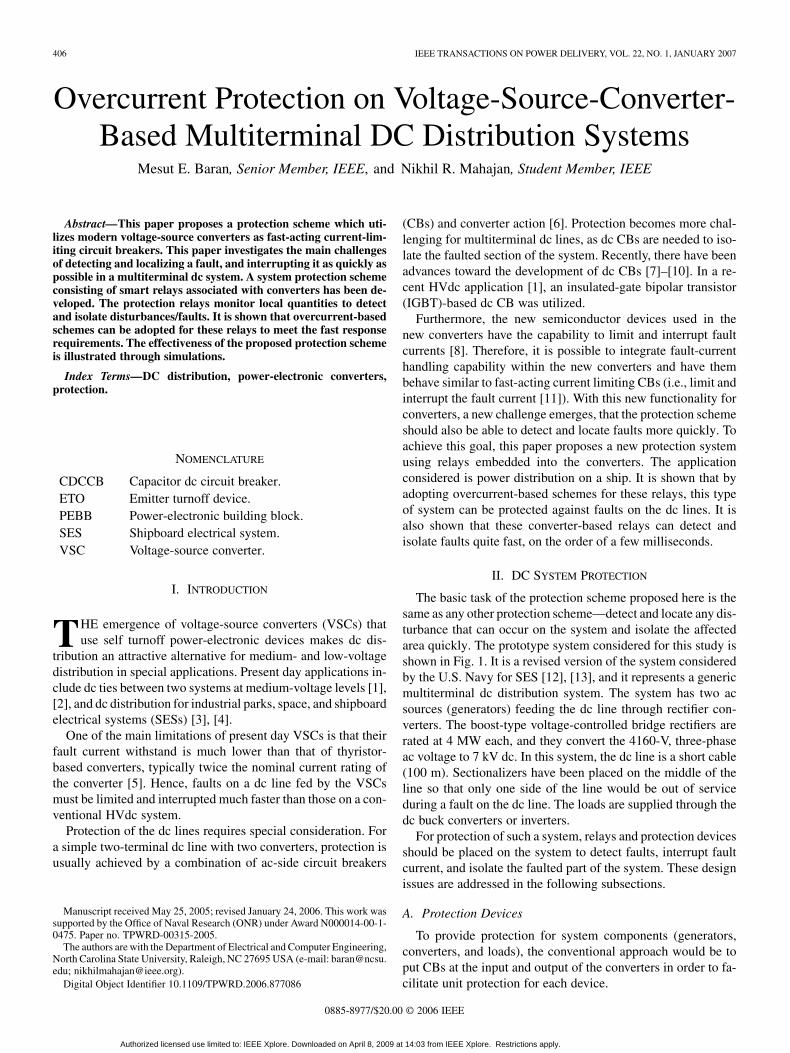
The basic task of the protection scheme proposed here is thesame as any other protection scheme—detect and locate any dis-turbance that can occur on the system and isolate the affectedarea quickly. The prototype system considered for this study isshown in Fig. 1. It is a revised version of the system consideredby the U.S. Navy for SES [12], [13], and it represents a genericmultiterminal dc distribution system. The system has two acsources (generators) feeding the dc line through rectifier con-verters. The boost-type voltage-controlled bridge rectifiers arerated at 4 MW each, and they convert the 4160-V, three-phaseac voltage to 7 kV dc. In this system, the dc line is a short cable(100 m). Sectionalizers have been placed on the middle of theline so that only one side of the line would be out of serviceduring a fault on the dc line. The loads are supplied through thedc buck converters or inverters.
For protection of such a system, relays and protection devicesshould be placed on the system to detect faults, interrupt faultcurrent, and isolate the faulted part of the system. These designissues are addressed in the following subsections.
A. Protection Devices
To provide protection for system components (generators,converters, and loads), the conventional approach would be toput CBs at the input and output of the converters in order to fa-cilitate unit protection for each device.
Authorized licensed use limited to: IEEE Xplore. Downloaded on April 8, 2009 at 14:03 from IEEE Xplore. Restrictions apply.
BARAN AND MAHAJAN: VSC-BASED MULTITERMINAL DC DISTRIBUTION SYSTEMS 407
Fig. 1. Prototype dc distribution system with CBs.
The alternative approach, which has been considered here,is to use the converters themselves for fault current interrup-tion. In [11], for example, it has been shown that VSCs usedfor dc distribution can limit fault current and interrupt it and,hence, they can be used as current-limiting CBs. Furthermore,converters have overcurrent protection on the power semicon-ductor switches to protect the switches when the current througha switch gets close to its limit. Therefore, this switch level pro-tection employed on the converter can serve as a backup over-current protection relay.
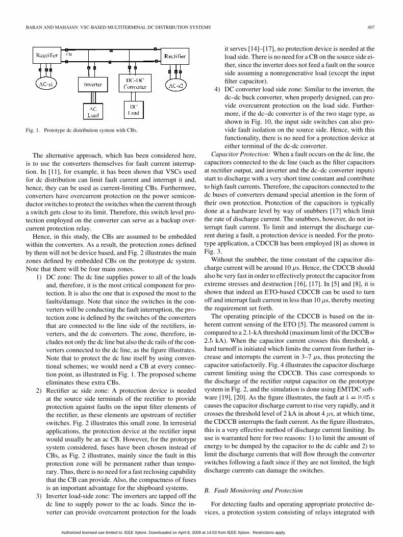
Hence, in this study, the CBs are assumed to be embeddedwithin the converters. As a result, the protection zones definedby them will not be device based, and Fig. 2 illustrates the mainzones defined by embedded CBs on the prototype dc system.Note that there will be four main zones.
1) DC zone: The dc line supplies power to all of the loadsand, therefore, it is the most critical component for pro-tection. It is also the one that is exposed the most to thefaults/damage. Note that since the switches in the con-verters will be conducting the fault interruption, the pro-tection zone is defined by the switches of the convertersthat are connected to the line side of the rectifiers, in-verters, and the dc converters. The zone, therefore, in-cludes not only the dc line but also the dc rails of the con-verters connected to the dc line, as the figure illustrates.Note that to protect the dc line itself by using conven-tional schemes; we would need a CB at every connec-tion point, as illustrated in Fig. 1. The proposed schemeeliminates these extra CBs.
2) Rectifier ac side zone: A protection device is neededat the source side terminals of the rectifier to provideprotection against faults on the input filter elements ofthe rectifier, as these elements are upstream of rectifierswitches. Fig. 2 illustrates this small zone. In terrestrialapplications, the protection device at the rectifier inputwould usually be an ac CB. However, for the prototypesystem considered, fuses have been chosen instead ofCBs, as Fig. 2 illustrates, mainly since the fault in thisprotection zone will be permanent rather than tempo-rary. Thus, there is no need for a fast reclosing capabilitythat the CB can provide. Also, the compactness of fusesis an important advantage for the shipboard systems.
3) Inverter load-side zone: The inverters are tapped off thedc line to supply power to the ac loads. Since the in-verter can provide overcurrent protection for the loads
it serves [14]–[17], no protection device is needed at theload side. There is no need for a CB on the source side ei-ther, since the inverter does not feed a fault on the sourceside assuming a nonregenerative load (except the inputfilter capacitor).
4) DC converter load side zone: Similar to the inverter, thedc–dc buck converter, when properly designed, can pro-vide overcurrent protection on the load side. Further-more, if the dc–dc converter is of the two stage type, asshown in Fig. 10, the input side switches can also pro-vide fault isolation on the source side. Hence, with thisfunctionality, there is no need for a protection device ateither terminal of the dc-dc converter.
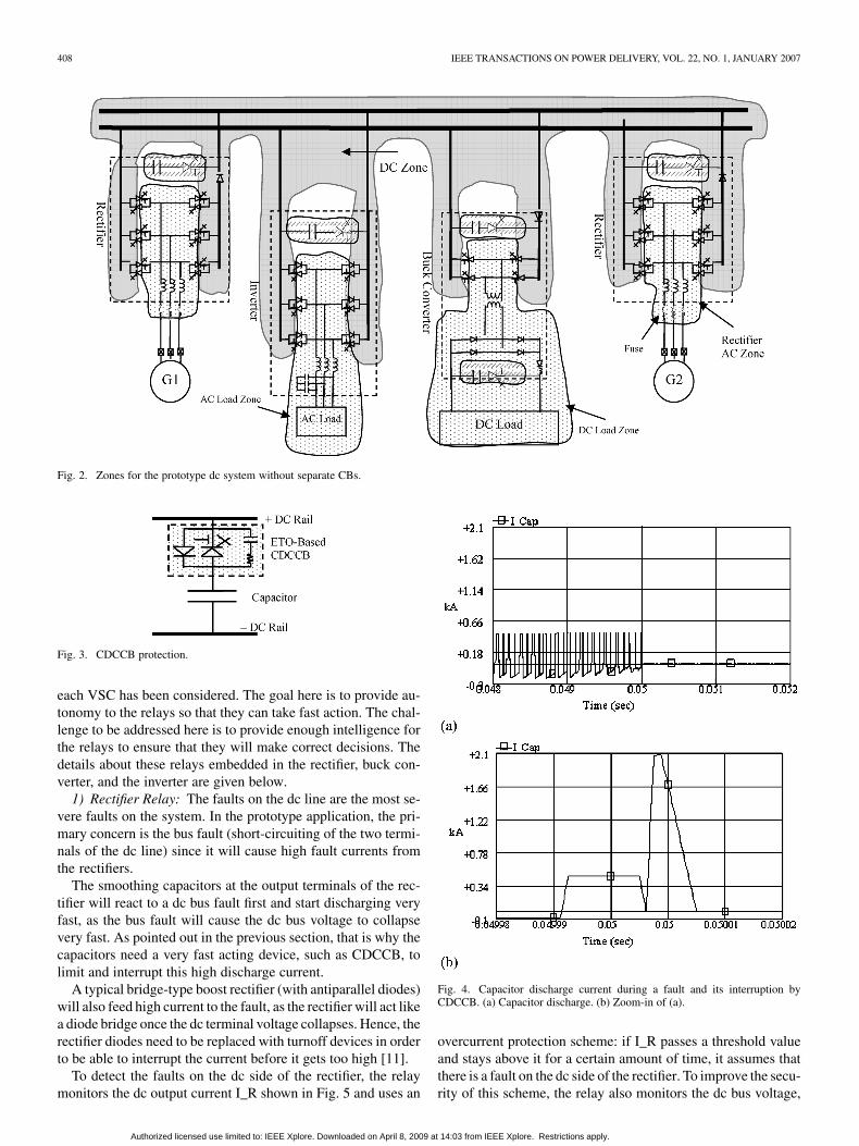
Capacitor Protection: When a fault occurs on the dc line, thecapacitors connected to the dc line (such as the filter capacitorsat rectifier output, and inverter and the dc–dc converter inputs)start to discharge with a very short time constant and contributeto high fault currents. Therefore, the capacitors connected to thedc buses of converters demand special attention in the form oftheir own protection. Protection of the capacitors is typicallydone at a hardware level by way of snubbers [17] which limitthe rate of discharge current. The snubbers, however, do not in-terrupt fault current. To limit and interrupt the discharge cur-rent during a fault, a protection device is needed. For the proto-type application, a CDCCB has been employed [8] as shown inFig. 3.
Without the snubber, the time constant of the capacitor dis-charge current will be around 10 s. Hence, the CDCCB shouldalso be very fast in order to effectively protect the capacitor fromextreme stresses and destruction [16], [17]. In [5] and [8], it isshown that indeed an ETO-based CDCCB can be used to turnoff and interrupt fault current in less than 10 s, thereby meetingthe requirement set forth.
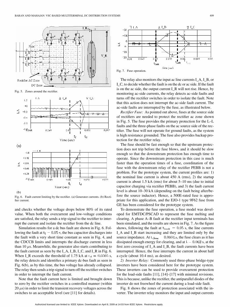
The operating principle of the CDCCB is based on the in-herent current sensing of the ETO [5]. The measured current iscompared to a 2.1-kA threshold (maximum limit of the DCCB
kA). When the capacitor current crosses this threshold, ahard turnoff is initiated which limits the current from further in-crease and interrupts the current in 3–7 s, thus protecting thecapacitor satisfactorily. Fig. 4 illustrates the capacitor dischargecurrent limiting using the CDCCB. This case corresponds tothe discharge of the rectifier output capacitor on the prototypesystem in Fig. 2, and the simulation is done using EMTDC soft-ware [19], [20]. As the figure illustrates, the fault at scauses the capacitor discharge current to rise very rapidly, and itcrosses the threshold level of 2 kA in about 4 s, at which time,the CDCCB interrupts the fault current. As the figure illustrates,this is a very effective method of discharge current limiting. Itsuse is warranted here for two reasons: 1) to limit the amount ofenergy to be dumped by the capacitor to the dc cable and 2) tolimit the discharge currents that will flow through the converterswitches following a fault since if they are not limited, the highdischarge currents can damage the switches.
B. Fault Monitoring and Protection
For detecting faults and operating appropriate protective de-vices, a protection system consisting of relays integrated with
Authorized licensed use limited to: IEEE Xplore. Downloaded on April 8, 2009 at 14:03 from IEEE Xplore. Restrictions apply.
408 IEEE TRANSACTIONS ON POWER DELIVERY, VOL. 22, NO. 1, JANUARY 2007
Fig. 2. Zones for the prototype dc system without separate CBs.
Fig. 3. CDCCB protection.
each VSC has been considered. The goal here is to provide au-tonomy to the relays so that they can take fast action. The chal-lenge to be addressed here is to provide enough intelligence forthe relays to ensure that they will make correct decisions. Thedetails about these relays embedded in the rectifier, buck con-verter, and the inverter are given below.
1) Rectifier Relay: The faults on the dc line are the most se-vere faults on the system. In the prototype application, the pri-mary concern is the bus fault (short-circuiting of the two termi-nals of the dc line) since it will cause high fault currents fromthe rectifiers.
The smoothing capacitors at the output terminals of the rec-tifier will react to a dc bus fault first and start discharging veryfast, as the bus fault will cause the dc bus voltage to collapsevery fast. As pointed out in the previous section, that is why thecapacitors need a very fast acting device, such as CDCCB, tolimit and interrupt this high discharge current.
A typical bridge-type boost rectifier (with antiparallel diodes)will also feed high current to the fault, as the rectifier will act likea diode bridge once the dc terminal voltage collapses. Hence, therectifier diodes need to be replaced with turnoff devices in orderto be able to interrupt the current before it gets too high [11].
To detect the faults on the dc side of the rectifier, the relaymonitors the dc output current I_R shown in Fig. 5 and uses an
Fig. 4. Capacitor discharge current during a fault and its interruption byCDCCB. (a) Capacitor discharge. (b) Zoom-in of (a).
overcurrent protection scheme: if I_R passes a threshold valueand stays above it for a certain amount of time, it assumes thatthere is a fault on the dc side of the rectifier. To improve the secu-rity of this scheme, the relay also monitors the dc bus voltage,
Authorized licensed use limited to: IEEE Xplore. Downloaded on April 8, 2009 at 14:03 from IEEE Xplore. Restrictions apply.
BARAN AND MAHAJAN: VSC-BASED MULTITERMINAL DC DISTRIBUTION SYSTEMS 409
Fig. 5. Zones around the rectifier.
Fig. 6. Fault current limiting by the rectifier. (a) Generator currents. (b) Recti-fier current.
and checks whether the voltage drops below 80% of its ratedvalue. When both the overcurrent and low-voltage conditionsare satisfied, the relay sends a trip signal to the rectifier to inter-rupt the current and isolate the rectifier from the dc line.
Simulation results for a dc bus fault are shown in Fig. 6. Fol-lowing the fault at , the bus capacitor discharges intothe fault with a very short time constant as seen in Fig. 4, andthe CDCCB limits and interrupts the discharge current in lessthan 10 s. Meanwhile, the generator also starts contributing tothe fault current as seen by the I_A, I_B, I_C, and I_R in Fig. 6.When I_R exceeds the threshold of 1.75 kA at s,the relay detects and identifies a primary dc-bus fault as seen inFig. 6(b), as by this time, the bus voltage has already collapsed.The relay then sends a trip signal to turn off the rectifier switchesin order to interrupt the fault current.
Note that the fault current here is limited and brought downto zero by the rectifier switches in a controlled manner (within20 s) in order to limit the transient recovery voltages across theswitches to an acceptable level (see [11] for details).
Fig. 7. Fuse operation.
The relay also monitors the input ac line currents I_A, I_B, orI_C, to decide whether the fault is on the dc or ac side. If the faultis on the ac side, the output current I_R will not rise. Hence, bymonitoring ac-side currents, the relay detects ac-side faults andturns off the rectifier switches in order to isolate the fault. Notethat this action does not interrupt the ac-side fault current. Theac-side faults are interrupted by the fuse, as illustrated below.
Rectifier Fuse: As pointed out above, fuses at the source sideof rectifiers are needed to protect the rectifier ac zone shownin Fig. 5. The fuse provides the primary protection for the L–Lfaults and the three-phase faults on the ac source side of the rec-tifier. The fuse will not operate for ground faults, as the systemis high resistance grounded. The fuse also provides backup pro-tection for the rectifier relay.
The fuse should be fast enough so that the upstream protec-tion does not trip before the fuse blows, and it should be slowenough so that the downstream protection has enough time tooperate. Since the downstream protection in this case is muchfaster than the operation times of a fuse, coordination of thefuse with the downstream relay of the rectifier PEBB is not aproblem. For the prototype system, the current profiles are: 1)the nominal line current is about 450 A (rms), 2) the startupcurrent is about 1.5 kA (rms) for about 5–10 ms (due to initialcapacitor charging via rectifier PEBB), and 3) the fault currentlevel is about 10–30 kA (depending on the fault being after/be-fore the source inductor). Hence, a 500E-rated fuse is appro-priate for this application, and the EJO-1 type 9F62 fuse fromGE has been considered for the prototype system.
To demonstrate the fuse operation, a fuse model was devel-oped for EMTDC/PSCAD to represent the fuse melting andclearing. A phase A–B fault at the rectifier input terminals hasbeen simulated, and the results are shown in Fig. 7. As the figureshows, following the fault at s, the line currentsI_A and I_B start increasing and they are limited only by thesource impedance. At , the fuse clears as it hasdissipated enough energy for clearing, and at s, at thefirst zero crossing of I_A and I_B, the fault currents have beeninterrupted. Hence, the fuse interrupts the current in about halfa cycle (about 10.4 ms), as desired.
2) Inverter Relay: Commonly used three-phase bridge-typeinverters have been considered here for the prototype system.These inverters can be used to provide overcurrent protectionfor the load-side faults [11], [14]–[17] with minimal revisions.This is because, unlike the rectifier, the antiparallel diodes of theinverter do not freewheel the current during a load-side fault.
Fig. 8 shows the zones of protection associated with the in-verter. The inverter relay monitors the input and output currents
Authorized licensed use limited to: IEEE Xplore. Downloaded on April 8, 2009 at 14:03 from IEEE Xplore. Restrictions apply.
410 IEEE TRANSACTIONS ON POWER DELIVERY, VOL. 22, NO. 1, JANUARY 2007
Fig. 8. Protection zones around the inverter.
, and , , , to detect and localize the faults. Note thatthe relay is responsible mainly for the faults in the load zone,as the upstream faults in the source zone are interrupted by therectifiers.
To illustrate the fault current interruption by the inverter, anovercurrent scheme is considered (although other more secureschemes are possible [14]–[17]). The inverter relay monitorsthe input current , and when the current passes the thresholdlimit, the relay assumes the fault. At the same time, if any of theoutput currents pass the corresponding threshold value, the faultis localized as the load-side fault.
Note that since the system is high resistance grounded, thefirst ground faults are not disruptive and, hence, only the lineand three-phase faults are considered for the prototype system.Simulation results for a three-phase fault at the load terminalsof the inverter are given in Fig. 9. The three-phase fault causesthe output voltage to collapse and, correspondingly, the currentstarts to increase. When the input current crosses the thresholdof 2.5 kA and stays above the threshold, the relay detects thefault and turns off the switches of the inverter to interrupt andisolate the fault. Note that the current decreases slowly to zero,rather than being chopped when the switches are turned off.This is due to the fact that the antiparallel diodes provide a free-wheeling path for the load current after the turnoff. As a result,there is very little transient recovery voltage on the switches.Note also that monitoring the output currents helps the relay tolocalize the fault (i.e., identify whether the fault is downstreamor internal to the inverter).
Note that the load considered here is passive. If there is amotor load that can regenerate, a diode on the input dc bus isneeded to prevent reverse current feed to a source-side fault.
3) Buck Converter Relay: dc–dc buck converters can alsoperform fault-current interruption when properly designed [11].A buck converter with an isolation transformer provides enoughflexibility for this purpose, and it is considered for the prototypeapplication. The converter in Fig. 10 uses an isolation trans-former with a 5:1 turns ratio to help buck the primary 7-kV dcvoltage to 800 V dc. Note that the switches do not use antipar-allel diodes, and this facilitates fault-current interruption andisolation by turning off all of the switches as will be illustratedhere.
The protection relay for the buck converter is mainly respon-sible for detecting and interrupting the faults in the load-side
Fig. 9. Fault current limiting by the inverter. (a) Inverter current profile duringa fault. (b) Output voltages.
Fig. 10. Zones around buck converter.
zone as Fig. 10 illustrates. The protection scheme considered forthis relay is similar to that of the inverter. The relay monitorsthe input current , output current , as well as transformercurrents and . The relay detects the existence of afault when crosses a threshold (0.5 kA). The relay localizesthe fault to the load side when the output current crosses thethreshold (2.5 kA) along with a simultaneous increase in .
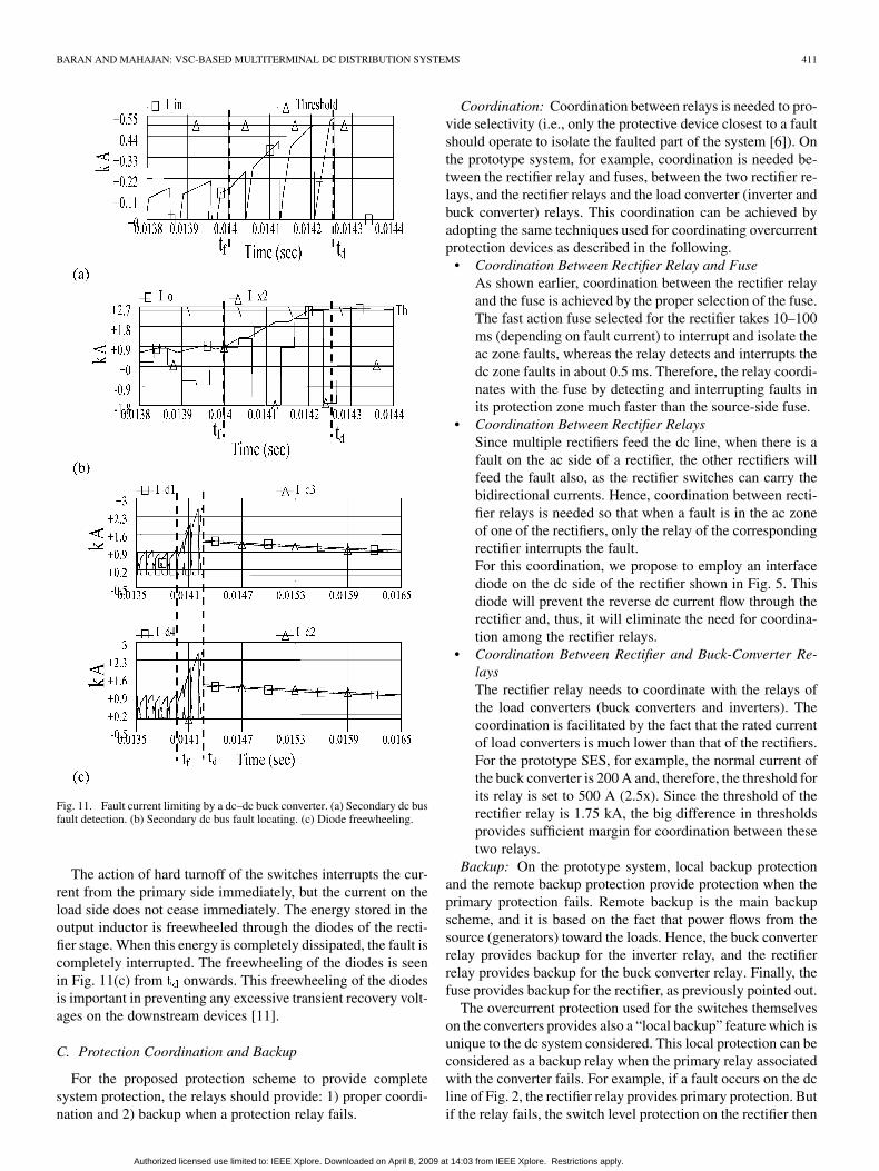
The simulation results are shown in Fig. 11 for a bus fault atthe load-side terminal at . The fault causes the cur-rent to increase as shown in Fig. 11(a). At ,the relay detects the fault as crosses the threshold of 0.5kA. Also, at , the currents and cross thethreshold of 2.5 kA as shown in Fig. 11(b). The relay thus iden-tifies the fault as the load-side bus fault. The protective actiontaken by the relay is to turn off the converter switches.
Authorized licensed use limited to: IEEE Xplore. Downloaded on April 8, 2009 at 14:03 from IEEE Xplore. Restrictions apply.
BARAN AND MAHAJAN: VSC-BASED MULTITERMINAL DC DISTRIBUTION SYSTEMS 411
Fig. 11. Fault current limiting by a dc–dc buck converter. (a) Secondary dc busfault detection. (b) Secondary dc bus fault locating. (c) Diode freewheeling.
The action of hard turnoff of the switches interrupts the cur-rent from the primary side immediately, but the current on theload side does not cease immediately. The energy stored in theoutput inductor is freewheeled through the diodes of the recti-fier stage. When this energy is completely dissipated, the fault iscompletely interrupted. The freewheeling of the diodes is seenin Fig. 11(c) from onwards. This freewheeling of the diodesis important in preventing any excessive transient recovery volt-ages on the downstream devices [11].
C. Protection Coordination and Backup
For the proposed protection scheme to provide completesystem protection, the relays should provide: 1) proper coordi-nation and 2) backup when a protection relay fails.
Coordination: Coordination between relays is needed to pro-vide selectivity (i.e., only the protective device closest to a faultshould operate to isolate the faulted part of the system [6]). Onthe prototype system, for example, coordination is needed be-tween the rectifier relay and fuses, between the two rectifier re-lays, and the rectifier relays and the load converter (inverter andbuck converter) relays. This coordination can be achieved byadopting the same techniques used for coordinating overcurrentprotection devices as described in the following.
• Coordination Between Rectifier Relay and FuseAs shown earlier, coordination between the rectifier relayand the fuse is achieved by the proper selection of the fuse.The fast action fuse selected for the rectifier takes 10–100ms (depending on fault current) to interrupt and isolate theac zone faults, whereas the relay detects and interrupts thedc zone faults in about 0.5 ms. Therefore, the relay coordi-nates with the fuse by detecting and interrupting faults inits protection zone much faster than the source-side fuse.
• Coordination Between Rectifier RelaysSince multiple rectifiers feed the dc line, when there is afault on the ac side of a rectifier, the other rectifiers willfeed the fault also, as the rectifier switches can carry thebidirectional currents. Hence, coordination between recti-fier relays is needed so that when a fault is in the ac zoneof one of the rectifiers, only the relay of the correspondingrectifier interrupts the fault.For this coordination, we propose to employ an interfacediode on the dc side of the rectifier shown in Fig. 5. Thisdiode will prevent the reverse dc current flow through therectifier and, thus, it will eliminate the need for coordina-tion among the rectifier relays.
• Coordination Between Rectifier and Buck-Converter Re-laysThe rectifier relay needs to coordinate with the relays ofthe load converters (buck converters and inverters). Thecoordination is facilitated by the fact that the rated currentof load converters is much lower than that of the rectifiers.For the prototype SES, for example, the normal current ofthe buck converter is 200 A and, therefore, the threshold forits relay is set to 500 A (2.5x). Since the threshold of therectifier relay is 1.75 kA, the big difference in thresholdsprovides sufficient margin for coordination between thesetwo relays.
Backup: On the prototype system, local backup protectionand the remote backup protection provide protection when theprimary protection fails. Remote backup is the main backupscheme, and it is based on the fact that power flows from thesource (generators) toward the loads. Hence, the buck converterrelay provides backup for the inverter relay, and the rectifierrelay provides backup for the buck converter relay. Finally, thefuse provides backup for the rectifier, as previously pointed out.
The overcurrent protection used for the switches themselveson the converters provides also a “local backup” feature which isunique to the dc system considered. This local protection can beconsidered as a backup relay when the primary relay associatedwith the converter fails. For example, if a fault occurs on the dcline of Fig. 2, the rectifier relay provides primary protection. Butif the relay fails, the switch level protection on the rectifier then
Authorized licensed use limited to: IEEE Xplore. Downloaded on April 8, 2009 at 14:03 from IEEE Xplore. Restrictions apply.
412 IEEE TRANSACTIONS ON POWER DELIVERY, VOL. 22, NO. 1, JANUARY 2007
provides local backup for the relay by turning off the rectifierswitches when the current through the switches approaches theirlimits.
III. CONCLUSION
This paper illustrates that protection of a multiterminal dc dis-tribution system can be simplified by utilizing the power-elec-tronic converters’ ability to act as fault current-limiting CBs. It isshown that by associating relays with the converters—rectifier,inverter, and dc–dc buck converter—and by adopting overcur-rent-based protection schemes for these relays, the faults on thesystem can be detected and localized very fast. The simulationresults on the prototype system illustrate that these relays canquickly detect and localize the faults within a few milliseconds.The relays in the proposed scheme are versatile in that they canperform both unit protection and overcurrent protection func-tions.
One challenge of the protection of dc systems is locating afault on the dc line. This is especially the case for the systemswhere the dc link is rather short and ungrounded. The over-current-based protection schemes are thus able to localize thefaults only to the zones upstream/downstream of the converters.This paper has focused on fault interruption and isolation. Theuse of sectionalizers to minimize the interruption is the secondstage—the reconfiguration stage—of fault management, and ithas been investigated in [21].
REFERENCES
[1] G. Asplund, “Application of HVDC light to power system enhance-ment,” presented at the IEEE Power Eng. Soc. Winter Meeting Singa-pore, 2000.
[2] U. Axelsson et al., “The Gotland HVDC light project-experiencesfrom trial and commercial operation,” presented at the CIRED 16thInt. Conf. Exhibition (IEE Conf. Publ. No. 482) Amsterdam, TheNetherlands, 2001.
[3] M. Baran and N. R. Mahajan, “DC distribution for industrial systems:Opportunities and challenges,” IEEE Trans. Ind. Appl., vol. 39, no. 6,pp. 1596–1601, Nov./Dec. 2003.
[4] N. Doerry, H. Robey, J. Amy, and C. Petry, “Powering the future withintegrated power system,” Naval Eng. J., vol. 108, p. 12, 1996.
[5] P. M. Anderson, Power System Protection. New York: IEEE Press,1999.
[6] B. Zhang and A. Q. Huang et al., “The built-in current sensor and over-current protection of the emitter turn-off (ETO) thyristor,” presented atthe Ind. Appl. Conf., Salt Lake City, UT, 2003.
[7] B. Pauli and G. Mauthe et al., “Development of a high current HVDCcircuit breaker with fast fault clearing capability,” IEEE Trans. PowerDel., vol. 3, no. 4, pp. 2072–2080, Oct. 1988.
[8] Z. Xu and B. Zhang et al., “The emitter turn-off thyristor-based DC cir-cuit breaker,” presented at the IEEE Power Eng. Soc. Winter Meeting,New York, 2002.
[9] J. Zyborski, T. Lipski, J. Czucha, and S. Hasan, “Hybrid arcless low-voltage ac/dc current limiting interrupting device,” IEEE Trans. PowerDel., vol. 15, no. 4, pp. 1182–1187, Oct. 2000.
[10] P. M. McEwan and S. B. Tennakoon, “A two-stage dc thyristor circuitbreaker,” IEEE Trans. Power Electron., vol. 12, no. 4, pp. 597–607, Jul.1997.
[11] N. R. Mahajan, “System protection for PEBB based dc distribution sys-tems,” Ph.D. dissertation, Dept. Elect. Comput. Eng., North CarolinaState Univ., Raleigh, NC, Nov. 2004.
[12] K. L. Butler, N. D. R. Sarma, C. Whitcomb, H. Do Carmo, and H.Zhang, “Shipboard systems deploy automated protection,” IEEEComput. Appl. Power, vol. 11, no. 2, pp. 31–36, Apr, 1998.
[13] J. G. Ciezki and R. W. Ashton, “Selection and stability issues associ-ated with a navy shipboard dc zonal electric distribution system,” IEEETrans. Power Del., vol. 15, no. 2, pp. 665–669, Apr. 2000.
[14] D. Kastha and B. K. Bose, “Investigation of fault modes of voltage-fedinverter system for induction motor drive,” IEEE Trans. Ind. Appl., vol.30, no. 4, pp. 1028–1038, Jul./Aug. 1994.
[15] A. Ghosh and G. Ledwich, Power Quality Enhancement Using CustomPower Devices. New York: Springer, 2002.
[16] R. Peuget, S. Courtine, and J.-P. Rognon, “Fault detection and isola-tion on a PWM inverter by knowledge-based model,” IEEE Trans. Ind.Appl., vol. 34, no. 6, pp. 1318–1326, Nov./Dec. 1998.
[17] F. Blaabjerg and J. K. Pedersen, “A new low-cost, fully fault-protectedPWM-VSI inverter with true phase-current information,” IEEE Trans.Power Electron., vol. 12, no. 1, pp. 187–197, Jan. 1997.
[18] E.-C. Nho, I.-D. Kim, and T. A. Lipo, “A new boost type rectifier for aDC power supply with frequent output short circuit,” presented at theIndustry Applications Conf., Phoenix, AZ, 1999.
[19] Manitoba HVDC Research Centre, “EMTDC, The electromagnetictransients & controls simulation engine”. Winnipeg, MB, Canada,2002.
[20] Manitoba HVDC Research Centre, “PSCAD, power systems computeraided design” . Winnipeg, MB, Canada, 2003.
[21] M. Baran and N. Mahajan, “System reconfiguration on shipboard DCzonal electrical system,” in Proc. IEEE Electric Ship TechnologiesSymp., Philadelphia, PA, Jul. 2004.
Mesut E. Baran (S’87–M’88–SM’05) receivedthe Ph.D. degree from the University of California,Berkeley, in 1988.
Currently, he is an Associate Professor at NorthCarolina State University, Raleigh. His research in-terests include the analysis and control of distributionand transmission systems.
Nikhil R. Mahajan (S’01) is currently pursuing thePh.D. degree in electrical engineering at North Car-olina State University, Raleigh.
His research focuses on the protection of power-electronic building blocks. His research interests arein the areas of power system protection and transmis-sion and computer-aided system analysis.
Authorized licensed use limited to: IEEE Xplore. Downloaded on April 8, 2009 at 14:03 from IEEE Xplore. Restrictions apply.