20

2 www.zero-max.com Phone 800.533.1731 763.546.4300 Fax 763.546.8260®
• For today’s most demanding servo motor andmotion control applications. CD Couplings areprecise, robust, and available in sizes and modelsfor every application
• High torsional stiffness and high dynamic loadcapacity ensure reliable machine operation
• Precise positioning under high speed reversingloads without fatigue for reliable 24/7 operation
• Unique patented composite disc design providesmisalignment capacity and long operational life
• Clamp style hub design provides a superior methodof shaft engagement
• Eco-Friendly, adapted to RoHS Directive with nobanned substances
These next-generation CD Couplingsallow you to transmit high horsepower ina small envelope. They are ideal for cyclicapplications where speed and repeatableaccuracy are critical to keep 24/7systems going.
CD Couplings withstand the punishmentand stress of a servo motor. Incomparison, other couplings may havehigh torsional stiffness specifications;however, they can be too brittle towithstand the punishment of high speedreversing applications.
The working part of a CD Coupling ismade of high precision compositematerial. This patented design has hightorsional stiffness, and yet allows formisalignment in high stress applications.CD Couplings have excellent chemicaland moisture resistance and operatewithout maintenance in hostileenvironments.
Standard and Custom CD Couplingsare available for every application. Doyou need higher misalignment and greatertorque capacity in your coupling? Needmore flexibility and torsional stiffness?Need a very large bore diametercoupling? Or a long spacer coupling?Zero-Max CD Couplings are available ina full range of styles, models and sizes tomeet those needs. Zero-Max will designand build a custom CD Coupling tohandle your unique application.
ZERO-MAX CD® COUPLINGS
3www.zero-max.com Phone 800.533.1731 763.546.4300 Fax 763.546.8260®
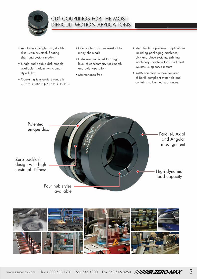
• Available in single disc, doubledisc, stainless steel, floatingshaft and custom models
• Single and double disk modelsavailable in aluminum clampstyle hubs
• Operating temperature range is-70° to +250° F (- 57° to + 121°C)
• Composite discs are resistant tomany chemicals
• Hubs are machined to a highlevel of concentricity for smoothand quiet operation
• Maintenance free
• Ideal for high precision applicationsincluding packaging machines,pick and place systems, printingmachinery, machine tools and mostsystems using servo motors
• RoHS compliant – manufacturedof RoHS compliant materials andcontains no banned substances
Four hub stylesavailable
Parallel, Axialand Angularmisalignment
High dynamicload capacity
Zero backlashdesign with hightorsional stiffness
Patentedunique disc
CD® COUPLINGS FOR THE MOSTDIFFICULT MOTION APPLICATIONS

4 www.zero-max.com Phone 800.533.1731 763.546.4300 Fax 763.546.8260®
The Single Flex Composite Disc Coupling is anexcellent choice for zero backlash applications.The unique design delivers two features that arenot often found in a precision coupling. Hightorsional stiffness and high durability!
The compact size and clamping system allow thiscoupling to fit into many applications. This designis also capable of being used in very high speedapplications with some modification.
• Zero Backlash• Torsionally Stiff• Excellent for Reversing Loads• Smooth Operating at High Speeds• Compact
CD® COUPLINGS SINGLE FLEX STEEL
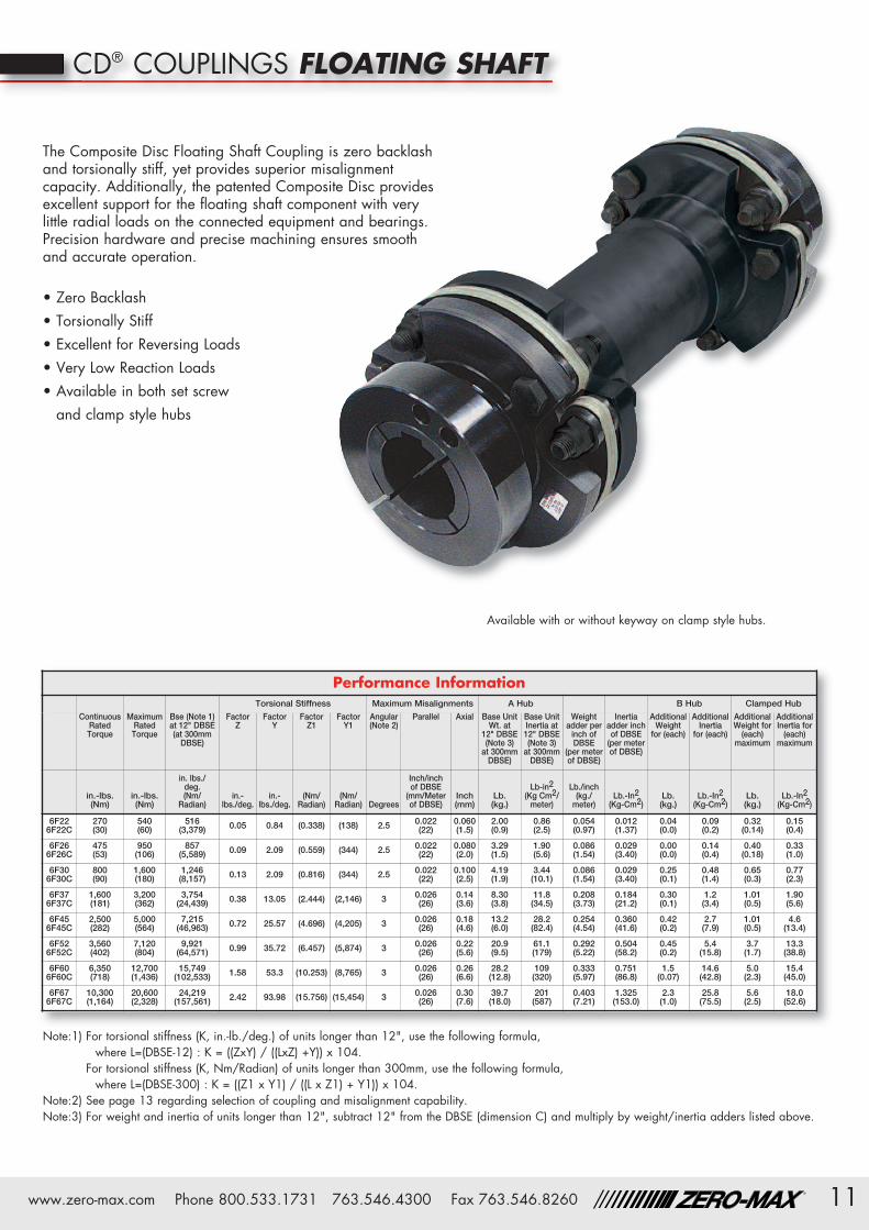
Available with or without keyway on clamp style hubs.
• Consult factory for speeds higher than those listed and balancing requirements, if necessary.• Consult factory for higher torque and higher torsional stiffness couplings.
Performance InformationMaximum Speed Misalignments A Hub B Hub Clamped Hub QD Hubs
Continuous Maximum Torsional A & B Clamp Angular Parallel AxialUnit
WeightUnitInertia
UnitWeight
UnitInertia
UnitWeight
UnitInertia
UnitWeight
RatedTorque
RatedTorque
Stiffness Hub StyleHub
at MaxBore
at MaxBore
at MaxBore
at MaxBore
at MaxBore
at MaxBore
w/Bushing
in-lbs(Nm)
in-lbs(Nm)
in-lbs/Deg.(Nm/Rad) (RPM) (RPM) Degrees
Inch(mm)
Inch(mm)
Lb.(kg.)
lb-in2
(kg-cm2)Lb.(kg.)
lb-in2
(kg-cm2)Lb.(kg.)
lb-in2
(kg-cm2)Lb.(kg.)
6A186A18C
180(20)
360(40)
1,800(11,650) 14,000 12,000 3 0.004
(0.10)0.030(0.8)
0.43(0.2)
0.16(0.47) – – 0.82
(0.37)0.35(1.02) –
6A226A22C
270(30)
540(60)
2,680(17,352) 12,000 11,000 3 0.006
(0.15)0.036(0.9)
0.88(0.4)
0.49(1.45)
0.96(0.44)
0.66(1.92)
1.57(0.71)
1.08(3.16) –
6A266A26C
475(53)
950(106)
3,100(20,100) 10,500 9,500 3 0.008
(0.20)0.043(1.1)
1.37(0.62)
0.93(2.72)
1.37(0.62)
1.21(3.54)
1.83(0.83)
1.57(4.58) –
6A306A30C
800(90)
1,600(180)
6,638(42,976) 9,000 8,000 3 0.010
(0.3)0.050(1.3)
2.0(0.9)
1.9(5.5)
2.5(1.1)
2.8(8.3)
3.51(1.59)
4.07(11.90) –
6A376A37C6A37QD
1,600(181)
3,200(362)
10,374(67,167) 7,400 6,700 3 0.013
(0.3)0.070(1.8)
3.6(1.6)
5.6(16.3)
4.2(1.9)
7.9(23.0)
6.00(2.72)
11.69(34.19)
3.7(1.7)
6A456A45C6A45QD
2,500(282)
5,000(564)
19,138(123,909) 6,100 5,600 3 0.015
(0.4)0.090(2.3)
6.4(2.9)
14.6(42.7)
7.2(3.3)
20.0(58.5)
10.58(4.80)
21.2(62.0)
6.8(3.1)
6A526A52C6A52QD
3,560(402)
7,120(804)
26,049(168,656) 5,200 4,800 3 0.018
(0.5)0.110(2.8)
10.5(4.8)
32.4(94.8)
11.4(5.2)
43.2(126)
14.65(6.64)
53.0(155.1)
11.7(5.3)
6A606A60C6A60QD
6,350(718)
12,700(1,436)
41,485(268,595) 4,600 4,400 3 0.020
(0.5)0.130(3.3)
15.3(7.0)
61.3(179)
18.4(8.4)
90.6(265)
23.2(10.5)
116.4(340.4)
15.8(7.2)
6A676A67C6A67QD
10,300(1,164)
20,600(2,328)
61,948(401,084) 4,300 4,100 3 0.022
(0.6)0.150(3.8)
22.0(10.0)
111(325)
26.5(12.0)
163(477)
35.0(15.9)
205.0(600.0)
20.5(9.3)
6A776A77QD
15,600(1,763)
31,200(3,526)
94,107(609,303) 3,900 – 3 0.025
(0.6)0.160(4.6)
31.3(14.2)
209(612)
38.5(17.5)
318(931) – – 29.5
(13.4)
6A90 25,000(2,825)
50,000(5,650)
160,653(1,040,162) 3,600 – 3 0.030
(0.8)0.180(4.6)
49.9(22.7)
461(1,349)
62.6(28.5)
722(2,113) – – –
6A105 34,900(3,944)
69,800(7,888)
244,204(1,581,120) 3,300 – 3 0.035
(0.9)0.210(5.3)
81.5(37.0)
1,046(3,061)
98.3(44.7)
1,572(4,600) – – –
6A120 47,200(5,333)
94,400(10,666)
328,095(2,124,275) 3,000 – 3 0.040
(1.0)0.250(6.4)
124.0(56.4)
2,054(6,011)
141.0(64.1)
3,100(9,070) – – –

5www.zero-max.com Phone 800.533.1731 763.546.4300 Fax 763.546.8260®
E
AL
D MAXB
C
F MAX
QDH
L
CB
LB
T
AGaEa
GbA
Eb
• ”X” dimension is the minimum bolt travel required beyondthe hub to disassemble the disc pack from the hubs.
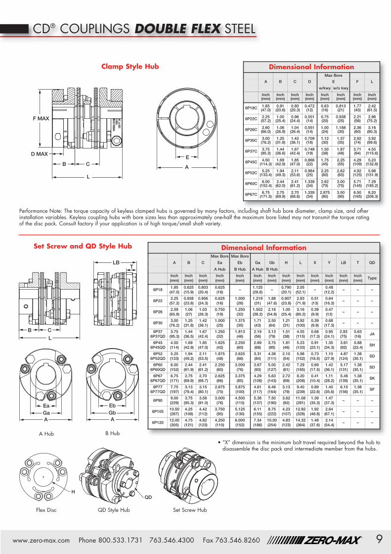
Performance Note: The torque capacity of keyless clamped hubs is governed by many factors, including shaft hub bore diameter, clamp size, andother installation variables. Keyless coupling hubs with bore sizes less than approximately one-half the maximum bore listed may not transmit thetorque rating of the disc pack. Consult factory if your application is of high torque/small keyless shaft variety.
Dimensional InformationMax Bore
A B C D E F L
w/kwy w/okwy
Inch(mm)
Inch(mm)
Inch(mm)
Inch(mm)
Inch(mm)
Inch(mm)
Inch(mm)
Inch(mm)
6A18C 1.85(47.0)
0.81(20.6)
0.28(7.1)
0.472(12)
0.63(16)
0.813(21)
1.77(45)
1.88(47.8)
6A22C 2.25(57.2)
1.00(25.4)
0.31(7.9)
0.551(14)
0.75(20)
0.938(25)
2.21(56)
2.31(58.7)
6A26C 2.60(66.0)
1.06(26.9)
0.31(7.9)
0.551(14)
1.00(24)
1.188(30)
2.36(60)
2.43(61.7)
6A30C 3.00(76.2)
1.25(31.8)
0.46(11.7)
0.709(18)
1.12(30)
1.37(35)
2.92(74)
2.96(75.2)
6A37C 3.75(95.3)
1.44(36.6)
0.52(13.2)
0.748(19)
1.50(38)
1.87(48)
3.71(94)
3.40(86.4)
6A45C 4.50(114.3)
1.69(42.9)
0.58(14.7)
0.866(22)
1.75(45)
2.25(55)
4.29(109)
3.96(100.6)
6A52C 5.25(133.4)
1.94(49.3)
0.65(16.5)
0.984(25)
2.25(60)
2.62(65)
4.92(125)
4.52(114.8)
6A60C 6.00(152.4)
2.44(62.0)
0.77(19.6)
1.339(34)
2.62(70)
3.00(75)
5.71(145)
5.64(143.3)
6A67C 6.75(171.5)
2.75(69.9)
0.86(21.8)
1.339(34)
2.875(80)
3.50(90)
6.50(165)
6.36(161.5)
Dimensional InformationMaxBore
MaxBore
A B C Ea Eb Ga Gb H L X LB T QD
A Hub B Hub A Hub B Hub
Inch(mm)
Inch(mm)
Inch(mm)
Inch(mm)
Inch(mm)
Inch(mm)
Inch(mm)
Inch(mm)
Inch(mm)
Inch(mm)
Inch(mm)
Inch(mm)
BushingType
6A18 1.85(47.0)
0.625(15.9)
0.276(7.0)
0.625(16) – 1.13
(28.6) – 0.79(20.1)
1.53(38.8)
0.0(0) – – –
6A22 2.25(57.2)
0.94(23.8)
0.31(7.8)
0.625(16)
1.000(26)
1.22(31)
1.88(47.6)
0.91(23.1)
2.18(55.4)
0.51(13) – – –
6A26 2.59(66)
1.06(27.0)
0.31(7.8)
0.750(19)
1.250(32)
1.50(38.2)
2.16(54.8)
1.00(25.4)
2.43(61.7)
0.39(9.9) – – –
6A30 3.00(76.2)
1.25(31.8)
0.46(11.7)
1.000(25)
1.375(35)
1.71(43)
2.50(64)
1.21(31)
2.96(75)
0.39(9.9) – – –
6A376A37QD
3.75(95.3)
1.44(36.5)
0.52(13.3)
1.250(32)
1.813(46)
2.19(56)
3.13(79)
1.51(38)
3.40(86)
0.68(17.3)
1.78(45.2)
0.63(16) JA
6A456A45QD
4.50(114)
1.69(42.9)
0.58(14.8)
1.625(42)
2.250(60)
2.69(68)
3.75(95)
1.81(46)
3.96(101)
0.91(23.1)
2.34(59.5)
0.88(22.4) SH
6A526A52QD
5.25(133)
1.94(49.2)
0.65(16.4)
1.875(48)
2.625(66)
3.31(84)
4.38(111)
2.10(54)
4.52(115)
0.73(18.5)
3.41(87)
1.38(35.1) SD
6A606A60QD
6.00(152)
2.44(61.9)
0.77(19.5)
2.250(60)
3.000(76)
3.67(93)
5.00(127)
2.42(61)
5.64(143)
0.69(17.5)
3.53(90)
1.38(35.1) SD
6A676A67QD
6.75(172)
2.75(69.9)
0.86(21.8)
2.625(66)
3.375(85)
4.29(109)
5.63(143)
2.72(69)
6.36(162)
0.41(10.4)
3.62(92)
1.38(35.1) SK
6A776A77QD
7.75(197)
3.13(79.4)
1.01(25.7)
2.875(75)
3.875(100)
4.61(117)
6.46(164)
3.13(79)
7.26(185)
0.89(22.6)
4.01(102)
1.50(38.1) SF
6A90 9.00(229)
3.75(95.3)
1.13(28.8)
3.000(76)
4.500(115)
5.38(137)
7.50(191)
3.62(92)
8.63(219)
1.39(35.3) – – –
6A105 10.50(267)
4.25(108)
1.45(36.8)
3.750(95)
5.125(130)
6.11(155)
8.75(222)
4.23(107)
9.95(253)
1.92(48.8) – – –
6A120 12.00(305)
4.75(121)
1.54(39.0)
4.250(110)
6.000(152)
7.34(186)
10.00(254)
4.83(123)
11.04(280)
1.48(37.6) – – –
Clamp Style Hub
Set Screw and QD Style Hub
CD® COUPLINGS SINGLE FLEX STEEL
Set Screw HubQD Style HubFlex Disc
A Hub B Hub

6 www.zero-max.com Phone 800.533.1731 763.546.4300 Fax 763.546.8260®
EA
L
D MAXB
C
F MAX
The Aluminum hub version of our Single Flex Composite DiscCoupling has very low weight and inertia, making it an excellentchoice for servo motor applications. The unique design deliverstwo features that are not often found in a precision coupling. Hightorsional stiffness and high durability!
The compact size, low inertia, and clamping system enable thiscoupling to fit into many applications.
• Zero Backlash• Torsionally Stiff• Excellent for Reversing Loads• Smooth Operating at High Speeds• Compact
CD® COUPLINGS SINGLE FLEX ALUMINUM
Available with or without keyway on clamp style hubs.
Dimensional InformationMax Bore
A B C D E F L
w/kwy w/o kwy
Inch(mm)
Inch(mm)
Inch(mm)
Inch(mm)
Inch(mm)
Inch(mm)
Inch(mm)
Inch(mm)
6A18-AC 1.85(47.0)
0.81(20.6)
0.28(7.1)
0.472(12)
0.63(16)
0.813(21)
1.77(45)
1.88(47.8)
6A22-AC 2.25(57.2)
1.00(25.4)
0.31(7.9)
0.551(14)
0.75(20)
0.938(25)
2.21(56)
2.31(58.7)
6A26-AC 2.60(66.0)
1.06(26.9)
0.31(7.9)
0.551(14)
1.00(24)
1.188(30)
2.36(60)
2.43(61.7)
6A30-AC 3.00(76.2)
1.25(31.8)
0.46(11.7)
0.709(18)
1.12(30)
1.37(35)
2.92(74)
2.96(75.2)
6A37-AC 3.75(95.3)
1.44(36.6)
0.52(13.2)
0.748(19)
1.50(38)
1.87(48)
3.71(94)
3.40(86.4)
6A45-AC 4.50(114.3)
1.69(42.9)
0.58(14.7)
0.866(22)
1.75(45)
2.25(55)
4.29(109)
3.96(100.6)
6A52-AC 5.25(133.4)
1.94(49.3)
0.65(16.5)
0.984(25)
2.25(60)
2.62(65)
4.92(125)
4.52(114.8)
6A60-AC 6.00(152.4)
2.44(62.0)
0.77(19.6)
1.339(34)
2.62(70)
3.00(75)
5.71(145)
5.64(143.3)
• Consult factory for speeds higherthan those listed and balancingrequirements, if necessary.
• Consult factory for higher torque andhigher torsional stiffness couplings.
Performance InformationMaximumSpeed Misalignments Clamped Hub
Continuous Maximum Torsional Clamp Angular Parallel Axial Unit Weight Unit InertiaRatedTorque
RatedTorque
Stiffness StyleHub
at MaxBore
at 1/2 MaxBore
at MaxBore
at 1/2Max Bore
in-lbs(Nm)
in-lbs(Nm)
in-lbs/Deg.(Nm/Rad) (RPM) Degrees
Inch(mm)
Inch(mm)
Lb.(kg.)
Lb.(kg.)
lb-in2(kg-cm2)
lb-in2(kg-cm2)
6A18-AC 180(20)
360(40)
1,800(11,650) 15,000 3 0.004
(0.10)0.030(0.8)
0.32(0.15)
0.31(0.14)
0.15(0.43)
0.13(0.37)
6A22-AC 270(30)
540(60)
2,680(17,352) 13,500 3 0.006
(0.15)0.036(0.9)
0.67(0.30)
0.51(0.23)
0.50(1.45)
0.31(0.90)
6A26-AC 475(53)
950(106)
3,100(20,100) 11,500 3 0.008
(0.20)0.043(1.0)
0.77(0.35)
0.66(0.30)
0.68(1.98)
0.45(1.32)
6A30-AC 800(90)
1,600(180)
6,638(42,976) 9,500 3 0.010
(0.3)0.050(1.3)
1.46(0.66)
1.03(0.47)
1.78(5.21)
1.04(3.04)
6A37-AC 1,600(181)
3,200(362)
10,374(67,167) 8,000 3 0.013
(0.3)0.070(1.8)
2.58(1.17)
1.74(0.79)
5.17(15.12)
2.82(8.26)
6A45-AC 2,500(282)
5,000(564)
19,138(123,909) 6,700 3 0.015
(0.4)0.090(2.3)
4.50(2.04)
3.23(1.46)
10.00(29.26)
7.26(21.24)
6A52-AC 3,560(402)
7,120(804)
26,049(168,656) 5,800 3 0.018
(0.5)0.110(2.8)
6.07(2.75)
5.01(2.27)
18.9(55.2)
14.8(43.4)
6A60-AC 6,350(718)
12,700(1,436)
41,485(268,595) 5,200 3 0.020
(0.5)0.130(3.3)
9.74(4.42)
7.64(3.46)
40.3(117.8)
28.3(82.7)
Clamp Style Hub
Performance Note: The torque capacity of keyless clamped hubs is governed by many factors, including shaft hub bore diameter, clamp size,and other installation variables. Keyless coupling hubs with bore sizes less than approximately one-half the maximum bore listed may nottransmit the torque rating of the disc pack. Consult factory if your application is of high torque/small shaft variety.

7www.zero-max.com Phone 800.533.1731 763.546.4300 Fax 763.546.8260®
H
AGaEa
L
BC
E
AL
D MAXB
C
F MAX
The Single Flex Composite Disc Stainless Steel coupling is an excellentchoice for zero backlash applications that require stainless steel. Thehub and hardware are made from 300 Series stainless steel and thecomposite disc material is highly resistant to many harsh chemicals.
If your needs require a size of coupling that is not shown below,please contact Zero-Max.
CD® COUPLINGS SINGLE FLEX STAINLESS STEEL
Dimensional InformationMaxBore
A B C Ea Ga H L X
A Hub A Hub
Inch(mm)
Inch(mm)
Inch(mm)
Inch(mm)
Inch(mm)
Inch(mm)
Inch(mm)
Inch(mm)
6A30-SS 3.00(76.2)
1.25(31.8)
0.46(11.7)
1.000(25)
1.71(43)
1.21(31)
2.96(75)
0.39(9.9)
6A37-SS 3.75(95.3)
1.44(36.5)
0.52(13.3)
1.250(32)
2.19(56)
1.51(38)
3.40(86)
0.68(17.3)
6A45-SS 4.50(114)
1.69(42.9)
0.58(14.8)
1.625(42)
2.69(68)
1.81(46)
3.96(101)
0.91(23.1)
6A52-SS 5.25(133)
1.94(49.2)
0.65(16.4)
1.875(48)
3.31(84)
2.10(54)
4.52(115)
0.73(18.5)
• Consult factory for speedshigher than those listed andbalancing requirements,if necessary.
• Consult factory for highertorque and higher torsionalstiffness couplings.
Dimensional InformationMax Bore
A B C D E F L
w/kwy w/o kwy
Inch(mm)
Inch(mm)
Inch(mm)
Inch(mm)
Inch(mm)
Inch(mm)
Inch(mm)
Inch(mm)
6A30C-SS3.00(76.2)
1.25(31.8)
0.46(11.7)
0.69(17.5)
1.12(28)
1.37(35)
2.63(66.8)
2.96(75.2)
6A37C-SS3.75(95.3)
1.44(36.6)
0.52(13.2)
0.75(19.1)
1.50(38)
1.87(48)
3.25(82.6)
3.40(86.4)
6A45C-SS4.50(114.3)
1.69(42.9)
0.58(14.7)
0.75(19.1)
1.62(42)
2.00(50)
3.50(88.9)
3.96(100.6)
6A52C-SS5.25(133.4)
1.94(49.3)
0.65(16.5)
0.88(22.4)
2.12(55)
2.62(65)
4.25(108.0)
4.52(114.8)
Performance InformationMaximum Speed Misalignments A Hub Clamped Hub
Continuous Maximum Torsional A & B Clamp Angular Parallel Axial Unit Weight Unit Inertia Unit Weight Unit InertiaRatedTorque
RatedTorque
Stiffness Hub Style Hub at MaxBore
at MaxBore
at MaxBore
at MaxBore
in-lbs(Nm)
in-lbs(Nm)
in-lbs/Deg.(Nm/Rad) (RPM) (RPM) Degrees
Inch(mm)
Inch(mm)
Lb.(kg.)
lb-in2(kg-cm2)
Lb.(kg.)
lb-in2(kg-cm2)
6A30-SS6A30C-SS
800(90)
1,600(181)
6,638(42,976) 9,000 8,000 3 0.010
(0.3)0.050(1.3)
2.0(0.9)
1.9(5.5)
2.88(1.31)
3.11(9.11)
6A37-SS6A37C-SS
1,600(181)
3,200(362)
10,374(67,167) 7,400 6,700 3 0.013
(0.3)0.070(1.8)
3.6(1.6)
5.6(16.3)
6.04(2.74)
9.62(28.13)
6A45-SS6A45C-SS
2,500(282)
5,000(564)
19,138(123,909) 6,100 5,600 3 0.015
(0.4)0.090(2.3)
6.4(2.9)
14.6(42.7)
7.65(3.47)
18.0(52.6)
6A52-SS6A52C-SS
3,560(402)
7,120(804)
26,049(168,656) 5,200 4,800 3 0.018
(0.5)0.110(2.8)
10.5(4.8)
32.4(94.8)
11.93(5.41)
38.9(113.8)
Clamp Style Hub
Performance Note: The torque capacity of keyless clamped hubs is governed by many factors, including shaft hub bore diameter, clamp size, andother installation variables. Keyless coupling hubs with bore sizes less than approximately one-half the maximum bore listed may not transmit thetorque rating of the disc pack. Consult factory if your application is of high torque/small shaft variety.
Set Screw Style Hub
• ”X” dimension is the minimum bolt travel required beyond the hub to disassemble the disc pack from the hubs.

8 www.zero-max.com Phone 800.533.1731 763.546.4300 Fax 763.546.8260®
The Double Flex Composite Disc Coupling is ideal forprecision applications that require more misalignmentcapacity than our Single Flex design. The coupling’s largemisalignment capacity, high torsional stiffness, and overallhigh performance specifications make this coupling agood choice for a wide variety of applications.
• Zero Backlash• Torsionally Stiff• Excellent for Reversing Loads• Smooth Operating at High Speeds• Compact• Very low reaction loads on shaft bearingsdue to misalignment
CD® COUPLINGS DOUBLE FLEX STEEL
Available with or without keyway on clamp style hubs.
• Consult factory for speeds higher than those listed and balancing requirements, if necessary.• Consult factory for higher torque and higher torsional stiffness couplings.
Performance InformationMaximum Speed Misalignments A Hub B Hub Clamped Hub QD Hubs
Continuous Maximum Torsional A & B Clamp Angular Parallel Axial Unit Weight Unit Inertia Unit Weight Unit Inertia Unit Weight Unit Inertia Unit WeightRatedTorque
RatedTorque
Stiffness Hub Style Hub at Max Bore at Max Bore at Max Bore at Max Bore at Max Bore at Max Bore w/Bushing
in-lbs(Nm)
in-lbs(Nm)
in-lbs/Deg.(Nm/Rad) (RPM) (RPM) Degrees
Inch(mm)
Inch(mm)
Lb.(kg.)
lb-in2(kg-cm2)
Lb.(kg.)
lb-in2(kg-cm2)
Lb.(kg.)
lb-in2(kg-cm2)
Lb.(kg.)
6P186P18C
180(20)
360(40)
850(5,500) 14,000 12,000 3 0.022
(0.56)0.060(1.5)
0.47(0.21)
0.19(0.56) – – 0.93
(0.42)0.40(1.17) –
6P226P22C
270(30)
540(36)
1,310(8,482) 12,000 11,000 3 0.026
(0.66)0.072(1.8)
1.10(0.50)
0.66(1.94)
1.18(0.54)
0.82(2.41)
1.79(0.81)
1.25(3.65) –
6P266P26C
475(53)
950(106)
1,500(9,712) 10,500 9,500 3 0.030
(0.76)0.086(2.2)
1.66(0.75)
1.19(3.47)
1.66(0.75)
1.46(4.28)
2.12(0.96)
1.82(5.31) –
6P306P30C
800(90)
1,600(181)
3,231(20,923) 9,000 8,000 3 0.039
(1.0)0.100(2.5)
2.5(1.1)
2.5(7.3)
3.0(1.3)
3.5(10.2)
4.01(1.82)
4.70(13.75) –
6P376P37C6P37QD
1,600(181)
3,200(362)
5,051(32,700) 7,400 6,700 3 0.049
(1.2)0.140(3.6)
4.5(2.1)
7.5(21.8)
5.1(2.3)
9.8(28.6)
6.25(2.83)
13.59(39.74)
4.0(1.8)
6P456P45C6P45QD
2,500(282)
5,000(564)
9,317(60,324) 6,100 5,600 3 0.052
(1.3)0.180(4.6)
7.9(3.6)
19.1(55.9)
8.7(4.0)
24.5(71.7)
12.1(5.5)
25.7(75.0)
8.1(3.7)
6P526P52C6P52QD
3,560(402)
7,120(804)
12,682(82,109) 5,100 4,800 3 0.062
(1.6)0.220(5.6)
12.8(5.8)
41.6(122)
13.7(6.2)
52.5(154)
16.9(7.6)
62.3(182.2)
13.9(6.3)
6P606P60C6P60QD
6,350(718)
12,700(1,436)
20,196(130,763) 4,600 4,400 3 0.069
(1.8)0.260(6.6)
18.4(8.4)
79.3(232)
21.5(9.8)
109(319)
26.3(11.9)
134.3(392.9)
18.9(8.6)
6P676P67C6P67QD
10,300(1,164)
20,600(2,328)
30,159(195,265) 4,300 4,100 3 0.076
(1.9)0.300(7.6)
26.2(11.9)
141(413)
30.7(14.0)
193(565)
39.2(17.8)
235(687)
24.7(11.2)
6P776P77QD
15,600(1,763)
31,200(3,526)
45,815(296,634) 3,300 – 3 0.089
(2.3)0.320(8.1)
38.5(17.5)
273(799)
45.8(20.8)
381(1115) – – 36.8
(16.7)
6P90 25,000(2,825)
50,000(5,650)
78,213(506,395) 2,800 – 3 0.101
(2.6)0.360(9.1)
61.4(27.9)
596(1744)
74.1(33.7)
857(2508) – – –
6P105 34,900(3,944)
69,800(7,888)
118,889(769,756) 2,500 – 3 0.126
(3.2)0.420(10.7)
101(45.9)
1362(3986)
118(53.6)
1888(5525) – – –
6P120 47,200(5,333)
94,400(10,666)
159,730(1,034,187) 2,100 – 3 0.137
(3.5)0.500(12.7)
150(68.2)
2600(7609)
167(76.0)
3646(10,670) – – –
9www.zero-max.com Phone 800.533.1731 763.546.4300 Fax 763.546.8260®
E
A
L
D MAX
F MAX
B C
QDH
Set Screw and QD Style Hub
Flex Disc
A Hub B Hub
AGaEa
GbA
Eb
L
B C
LBT
Clamp Style Hub
Performance Note: The torque capacity of keyless clamped hubs is governed by many factors, including shaft hub bore diameter, clamp size, and otherinstallation variables. Keyless coupling hubs with bore sizes less than approximately one-half the maximum bore listed may not transmit the torque ratingof the disc pack. Consult factory if your application is of high torque/small shaft variety.
• ”X” dimension is the minimum bolt travel required beyond the hub todisassemble the disc pack and intermediate member from the hubs.
Dimensional InformationMax Bore Max Bore
A B C Ea Eb Ga Gb H L X Y LB T QD
A Hub B Hub A Hub B Hub
Inch(mm)
Inch(mm)
Inch(mm)
Inch(mm)
Inch(mm)
Inch(mm)
Inch(mm)
Inch(mm)
Inch(mm)
Inch(mm)
Inch(mm)
Inch(mm)
Inch(mm)
Type
6P181.85(47.0)
0.625(15.9)
0.803(20.4)
0.625(16)
–1.125(28.6)
–0.790(20.1)
2.05(52.1)
–0.48(12.2)
– – –
6P222.25(57.2)
0.938(23.8)
0.956(24.3)
0.625(16)
1.000(26)
1.219(31)
1.88(47.6)
0.907(23.8)
2.83(71.9)
0.51(13)
0.64(16.3)
– – –
6P262.59(65.9)
1.06(27)
1.03(26.3)
0.750(19)
1.250(32)
1.502(38.2)
2.16(54.8)
1.00(25.4)
3.16(80.2)
0.39(9.9)
0.47(12)
– – –
6P303.00(76.2)
1.25(31.8)
1.42(36.1)
1.000(25)
1.375(35)
1.71(43)
2.50(64)
1.21(31)
3.92(100)
0.39(9.9)
0.68(17.3)
– – –
6P376P37QD
3.75(95.3)
1.44(36.5)
1.67(42.4)
1.250(32)
1.813(46)
2.19(56)
3.13(79)
1.51(38)
4.55(115)
0.68(17.3)
0.95(24.1)
2.93(75)
0.63(16)
JA
6P456P45QD
4.50(114)
1.69(42.9)
1.85(47.0)
1.625(42)
2.250(60)
2.69(68)
3.75(95)
1.81(46)
5.23(133)
0.91(23.1)
1.35(34.3)
3.61(92)
0.88(22.4)
SH
6P526P52QD
5.25(133)
1.94(49.2)
2.11(53.5)
1.875(48)
2.625(66)
3.31(84)
4.38(111)
2.10(54)
5.98(152)
0.73(18.5)
1.10(27.9)
4.87(124)
1.38(35.1)
SD
6P606P60QD
6.00(152)
2.44(61.9)
2.41(61.2)
2.250(60)
3.000(76)
3.67(93)
5.00(127)
2.42(61)
7.29(185)
0.69(17.5)
1.42(36.1)
5.17(131)
1.38(35.1)
SD
6P676P67QD
6.75(171)
2.75(69.9)
2.70(68.7)
2.625(66)
3.375(85)
4.29(108)
5.63(143)
2.72(69)
8.20(208)
0.41(10.4)
1.11(28.2)
5.46(139)
1.38(35.1)
SK
6P776P77QD
7.75(197)
3.13(79.4)
3.15(80.1)
2.875(75)
3.875(100)
4.61(117)
6.46(164)
3.13(79)
9.40(239)
0.89(22.6)
1.40(35.6)
6.15(156)
1.38(35.1)
SF
6P909.00(229)
3.75(95.3)
3.58(91.0)
3.000(76)
4.500(115)
5.38(137)
7.50(190)
3.62(92)
11.08(281)
1.39(35.3)
1.47(37.3)
– – –
6P10510.50(267)
4.25(108)
4.42(112)
3.750(95)
5.125(130)
6.11(155)
8.75(222)
4.23(107)
12.92(328)
1.92(48.8)
2.64(67.1)
– – –
6P12012.00(305)
4.75(121)
4.82(123)
4.250(110)
6.000(152)
7.34(186)
10.00(254)
4.83(123)
14.32(364)
1.48(37.6)
2.14(54.4)
– – –
Dimensional InformationMax Bore
A B C D E F L
w/kwy w/o kwy
Inch(mm)
Inch(mm)
Inch(mm)
Inch(mm)
Inch(mm)
Inch(mm)
Inch(mm)
Inch(mm)
6P18C 1.85(47.0)
0.81(20.6)
0.80(20.3)
0.472(12)
0.63(16)
0.813(21)
1.77(45)
2.42(61.5)
6P22C 2.25(57.2)
1.00(25.4)
0.96(24.4)
0.551(14)
0.75(20)
0.938(25)
2.21(56)
2.96(75.2)
6P26C 2.60(66.0)
1.06(26.9)
1.04(26.4)
0.551(14)
1.00(24)
1.188(30)
2.36(60)
3.16(80.3)
6P30C 3.00(76.2)
1.25(31.8)
1.42(36.1)
0.709(18)
1.12(30)
1.37(35)
2.92(74)
3.92(99.6)
6P37C 3.75(95.3)
1.44(36.6)
1.67(42.4)
0.748(19)
1.50(38)
1.87(48)
3.71(94)
4.55(115.6)
6P45C 4.50(114.3)
1.69(42.9)
1.85(47.0)
0.866(22)
1.75(45)
2.25(55)
4.29(109)
5.23(132.8)
6P52C 5.25(133.4)
1.94(49.3)
2.11(53.6)
0.984(25)
2.25(60)
2.62(65)
4.92(125)
5.98(151.9)
6P60C 6.00(152.4)
2.44(62.0)
2.41(61.2)
1.339(34)
2.62(70)
3.00(75)
5.71(145)
7.29(185.2)
6P67C 6.75(171.5)
2.75(69.9)
2.70(68.6)
1.339(34)
2.875(80)
3.50(90)
6.50(165)
8.20(208.3)
CD® COUPLINGS DOUBLE FLEX STEEL
Set Screw HubQD Style Hub
10 www.zero-max.com Phone 800.533.1731 763.546.4300 Fax 763.546.8260®
A
E
L
D MAX
F MAX
B C
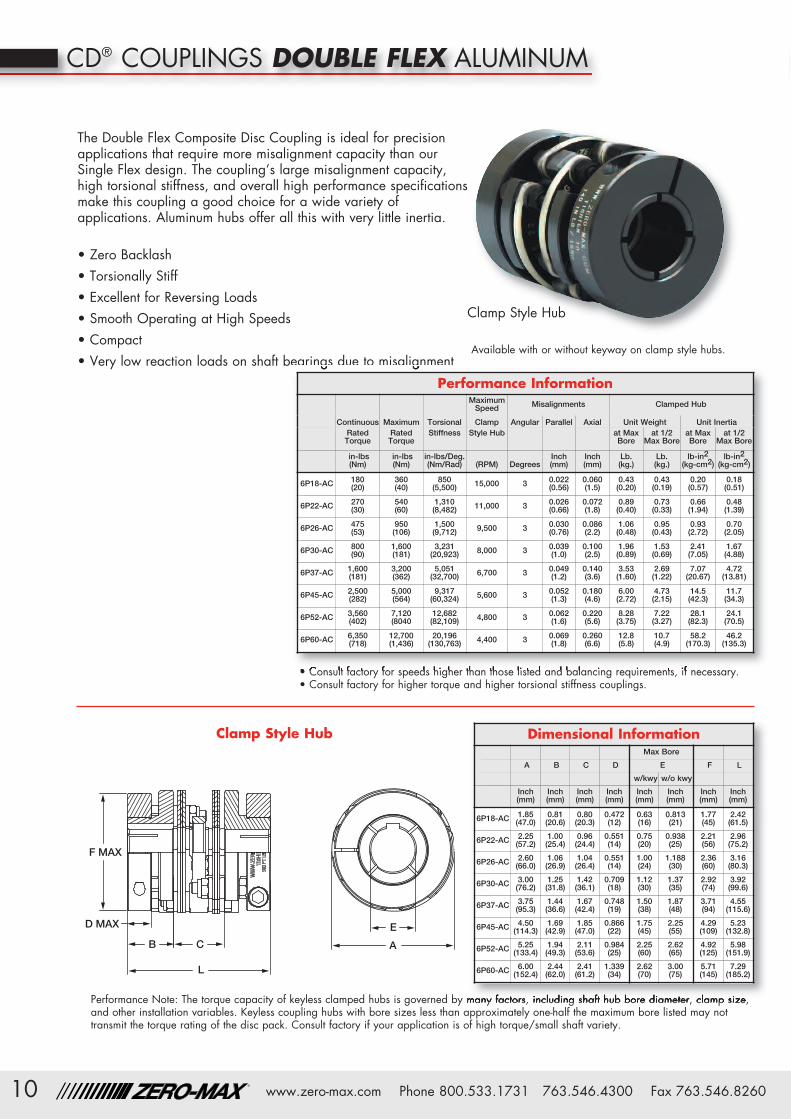
The Double Flex Composite Disc Coupling is ideal for precisionapplications that require more misalignment capacity than ourSingle Flex design. The coupling’s large misalignment capacity,high torsional stiffness, and overall high performance specificationsmake this coupling a good choice for a wide variety ofapplications. Aluminum hubs offer all this with very little inertia.
• Zero Backlash• Torsionally Stiff• Excellent for Reversing Loads• Smooth Operating at High Speeds• Compact• Very low reaction loads on shaft bearings due to misalignment
Clamp Style Hub
CD® COUPLINGS DOUBLE FLEX ALUMINUM
Performance Note: The torque capacity of keyless clamped hubs is governed by many factors, including shaft hub bore diameter, clamp size,and other installation variables. Keyless coupling hubs with bore sizes less than approximately one-half the maximum bore listed may nottransmit the torque rating of the disc pack. Consult factory if your application is of high torque/small shaft variety.
Dimensional InformationMax Bore
A B C D E F L
w/kwy w/o kwy
Inch(mm)
Inch(mm)
Inch(mm)
Inch(mm)
Inch(mm)
Inch(mm)
Inch(mm)
Inch(mm)
6P18-AC 1.85(47.0)
0.81(20.6)
0.80(20.3)
0.472(12)
0.63(16)
0.813(21)
1.77(45)
2.42(61.5)
6P22-AC 2.25(57.2)
1.00(25.4)
0.96(24.4)
0.551(14)
0.75(20)
0.938(25)
2.21(56)
2.96(75.2)
6P26-AC 2.60(66.0)
1.06(26.9)
1.04(26.4)
0.551(14)
1.00(24)
1.188(30)
2.36(60)
3.16(80.3)
6P30-AC 3.00(76.2)
1.25(31.8)
1.42(36.1)
0.709(18)
1.12(30)
1.37(35)
2.92(74)
3.92(99.6)
6P37-AC 3.75(95.3)
1.44(36.6)
1.67(42.4)
0.748(19)
1.50(38)
1.87(48)
3.71(94)
4.55(115.6)
6P45-AC 4.50(114.3)
1.69(42.9)
1.85(47.0)
0.866(22)
1.75(45)
2.25(55)
4.29(109)
5.23(132.8)
6P52-AC 5.25(133.4)
1.94(49.3)
2.11(53.6)
0.984(25)
2.25(60)
2.62(65)
4.92(125)
5.98(151.9)
6P60-AC 6.00(152.4)
2.44(62.0)
2.41(61.2)
1.339(34)
2.62(70)
3.00(75)
5.71(145)
7.29(185.2)
• Consult factory for speeds higher than those listed and balancing requirements, if necessary.• Consult factory for higher torque and higher torsional stiffness couplings.
Performance InformationMaximumSpeed Misalignments Clamped Hub
Continuous Maximum Torsional Clamp Angular Parallel Axial Unit Weight Unit InertiaRatedTorque
RatedTorque
Stiffness Style Hub at MaxBore
at 1/2Max Bore
at MaxBore
at 1/2Max Bore
in-lbs(Nm)
in-lbs(Nm)
in-lbs/Deg.(Nm/Rad) (RPM) Degrees
Inch(mm)
Inch(mm)
Lb.(kg.)
Lb.(kg.)
lb-in2(kg-cm2)
lb-in2(kg-cm2)
6P18-AC 180(20)
360(40)
850(5,500) 15,000 3 0.022
(0.56)0.060(1.5)
0.43(0.20)
0.43(0.19)
0.20(0.57)
0.18(0.51)
6P22-AC 270(30)
540(60)
1,310(8,482) 11,000 3 0.026
(0.66)0.072(1.8)
0.89(0.40)
0.73(0.33)
0.66(1.94)
0.48(1.39)
6P26-AC 475(53)
950(106)
1,500(9,712) 9,500 3 0.030
(0.76)0.086(2.2)
1.06(0.48)
0.95(0.43)
0.93(2.72)
0.70(2.05)
6P30-AC 800(90)
1,600(181)
3,231(20,923) 8,000 3 0.039
(1.0)0.100(2.5)
1.96(0.89)
1.53(0.69)
2.41(7.05)
1.67(4.88)
6P37-AC 1,600(181)
3,200(362)
5,051(32,700) 6,700 3 0.049
(1.2)0.140(3.6)
3.53(1.60)
2.69(1.22)
7.07(20.67)
4.72(13.81)
6P45-AC 2,500(282)
5,000(564)
9,317(60,324) 5,600 3 0.052
(1.3)0.180(4.6)
6.00(2.72)
4.73(2.15)
14.5(42.3)
11.7(34.3)
6P52-AC 3,560(402)
7,120(8040
12,682(82,109) 4,800 3 0.062
(1.6)0.220(5.6)
8.28(3.75)
7.22(3.27)
28.1(82.3)
24.1(70.5)
6P60-AC 6,350(718)
12,700(1,436)
20,196(130,763) 4,400 3 0.069
(1.8)0.260(6.6)
12.8(5.8)
10.7(4.9)
58.2(170.3)
46.2(135.3)
Clamp Style Hub
Available with or without keyway on clamp style hubs.
11www.zero-max.com Phone 800.533.1731 763.546.4300 Fax 763.546.8260®
CD® COUPLINGS FLOATING SHAFT
The Composite Disc Floating Shaft Coupling is zero backlashand torsionally stiff, yet provides superior misalignmentcapacity. Additionally, the patented Composite Disc providesexcellent support for the floating shaft component with verylittle radial loads on the connected equipment and bearings.Precision hardware and precise machining ensures smoothand accurate operation.
• Zero Backlash• Torsionally Stiff• Excellent for Reversing Loads• Very Low Reaction Loads• Available in both set screwand clamp style hubs
Note:1) For torsional stiffness (K, in.-lb./deg.) of units longer than 12", use the following formula,where L=(DBSE-12) : K = ((ZxY) / ((LxZ) +Y)) x 104.
For torsional stiffness (K, Nm/Radian) of units longer than 300mm, use the following formula,where L=(DBSE-300) : K = ((Z1 x Y1) / ((L x Z1) + Y1)) x 104.
Note:2) See page 13 regarding selection of coupling and misalignment capability.Note:3) For weight and inertia of units longer than 12", subtract 12" from the DBSE (dimension C) and multiply by weight/inertia adders listed above.
Performance InformationTorsional Stiffness Maximum Misalignments A Hub B Hub Clamped Hub
ContinuousRatedTorque
MaximumRatedTorque
Bse (Note 1)at 12" DBSE(at 300mmDBSE)
FactorZ
FactorY
FactorZ1
FactorY1
Angular(Note 2)
Parallel Axial Base UnitWt. at
12" DBSE(Note 3)at 300mmDBSE)
Base UnitInertia at12" DBSE(Note 3)at 300mmDBSE)
Weightadder perinch ofDBSE
(per meterof DBSE)
Inertiaadder inchof DBSE(per meterof DBSE)
AdditionalWeightfor (each)
AdditionalInertia
for (each)
AdditionalWeight for(each)
maximum
AdditionalInertia for(each)
maximum
in.-lbs.(Nm)
in.-lbs.(Nm)
in. lbs./deg.(Nm/
Radian)in.-
lbs./deg.in.-
lbs./deg.(Nm/
Radian)(Nm/
Radian) Degrees
Inch/inchof DBSE(mm/Meterof DBSE)
Inch(mm)
Lb.(kg.)
Lb-in2(Kg Cm2/meter)
Lb./inch(kg./meter)
Lb.-In2(Kg-Cm2)
Lb.(kg.)
Lb.-In2(Kg-Cm2)
Lb.(kg.)
Lb.-In2(Kg-Cm2)
6F226F22C
270(30)
540(60)
516(3,379) 0.05 0.84 (0.338) (138) 2.5 0.022
(22)0.060(1.5)
2.00(0.9)
0.86(2.5)
0.054(0.97)
0.012(1.37)
0.04(0.0)
0.09(0.2)
0.32(0.14)
0.15(0.4)
6F266F26C
475(53)
950(106)
857(5,589) 0.09 2.09 (0.559) (344) 2.5 0.022
(22)0.080(2.0)
3.29(1.5)
1.90(5.6)
0.086(1.54)
0.029(3.40)
0.00(0.0)
0.14(0.4)
0.40(0.18)
0.33(1.0)
6F306F30C
800(90)
1,600(180)
1,246(8,157) 0.13 2.09 (0.816) (344) 2.5 0.022
(22)0.100(2.5)
4.19(1.9)
3.44(10.1)
0.086(1.54)
0.029(3.40)
0.25(0.1)
0.48(1.4)
0.65(0.3)
0.77(2.3)
6F376F37C
1,600(181)
3,200(362)
3,754(24,439) 0.38 13.05 (2.444) (2,146) 3 0.026
(26)0.14(3.6)
8.30(3.8)
11.8(34.5)
0.208(3.73)
0.184(21.2)
0.30(0.1)
1.2(3.4)
1.01(0.5)
1.90(5.6)
6F456F45C
2,500(282)
5,000(564)
7,215(46,963) 0.72 25.57 (4.696) (4,205) 3 0.026
(26)0.18(4.6)
13.2(6.0)
28.2(82.4)
0.254(4.54)
0.360(41.6)
0.42(0.2)
2.7(7.9)
1.01(0.5)
4.6(13.4)
6F526F52C
3,560(402)
7,120(804)
9,921(64,571) 0.99 35.72 (6.457) (5,874) 3 0.026
(26)0.22(5.6)
20.9(9.5)
61.1(179)
0.292(5.22)
0.504(58.2)
0.45(0.2)
5.4(15.8)
3.7(1.7)
13.3(38.8)
6F606F60C
6,350(718)
12,700(1,436)
15,749(102,533) 1.58 53.3 (10.253) (8,765) 3 0.026
(26)0.26(6.6)
28.2(12.8)
109(320)
0.333(5.97)
0.751(86.8)
1.5(0.07)
14.6(42.8)
5.0(2.3)
15.4(45.0)
6F676F67C
10,300(1,164)
20,600(2,328)
24,219(157,561) 2.42 93.98 (15.756) (15,454) 3 0.026
(26)0.30(7.6)
39.7(18.0)
201(587)
0.403(7.21)
1.325(153.0)
2.3(1.0)
25.8(75.5)
5.6(2.5)
18.0(52.6)
Available with or without keyway on clamp style hubs.

12 www.zero-max.com Phone 800.533.1731 763.546.4300 Fax 763.546.8260®
GaA
Ea
A
Ec
XL
C (DBSE)B
GbA
Eb
F MAX
D MAX
Bc
Set Screw Style Hub
H
Flex Disc
A Hub B Hub
See the following page for maximum C Length and RPM data
CD® COUPLINGS FLOATING SHAFT
• Dimension L is equal to (2x B) + C (C is the DBSE or span)• Dimension C is always manufactured to application requirements• "X" dimension is minimum bolt travel required beyond the hub to disassemble disc packs from the hubs.
Dimensional InformationMax Bore
Set Screw Hub Clamp Hubs
A BA & B Hub
BcC Hub
D Max.C Hub
F Max.C Hub
EaA Hub
EbB Hub
EcC Hubw/kwy
EcC Hubw/o kwy
GaA Hub
GbB Hub
H X C min.(DBSE)
Inch(mm)
Inch(mm)
Inch(mm)
Inch(mm)
Inch(mm)
Inch(mm)
Inch(mm)
Inch(mm)
Inch(mm)
Inch(mm)
Inch(mm)
Inch(mm)
Inch(mm)
6F226F22C
2.25(57.2)
0.94(23.8)
1.00(25.4)
0.551(14)
2.21(56)
0.625(16)
1.000(26)
0.75(20)
0.938(25)
1.22(31.0)
1.88(47.6)
0.91(23.1)
0.51(13.0)
3.00(76.2)
6F266F26C
2.59(65.8)
1.06(27.0)
1.06(27.0)
0.551(14)
2.36(60)
0.750(19)
1.250(32)
1.00(24)
1.188(30)
1.50(38.1)
2.16(54.8)
1.00(25.4)
0.39(9.9)
3.00(76.2)
6F306F30C
3.00(76.2)
1.25(31.8)
1.25(31.8)
0.709(18)
2.92(74)
1.000(25)
1.375(35)
1.125(30)
1.375(35)
1.71(43.4)
2.50(63.5)
1.21(30.7)
0.39(9.9)
3.68(93.7)
6F376F37C
3.75(95.3)
1.44(36.5)
1.44(36.5)
0.748(19)
3.71(94)
1.250(32)
1.813(46)
1.500(38)
1.875(48)
2.19(55.6)
3.13(79.4)
1.51(38.4)
0.68(17.3)
4.5(114.3)
6F456F45C
4.50(114.3)
1.69(42.9)
1.69(42.9)
0.866(22)
4.29(109)
1.625(42)
2.250(60)
1.75(45)
2.25(55)
2.69(68.3)
3.75(95.3)
1.81(46.0)
0.91(23.1)
5.50(139.7)
6F526F52C
5.25(133.4)
1.94(49.2)
1.94(49.2)
0.984(25)
4.92(125)
1.875(48)
2.625(66)
2.25(60)
2.625(65)
3.31(84.1)
4.38(111.1)
2.10(53.3)
0.73(18.5)
6.5(165.1)
6F606F60C
6.00(152.4)
2.44(61.9)
2.44(61.9)
1.339(34)
5.71(145)
2.250(60)
3.000(76)
2.62(70)
3.000(75)
3.67(93.2)
5.00(127.0)
2.42(61.5)
0.69(17.5)
7.00(178)
6F676F67C
6.75(171.5)
2.75(69.9)
2.75(69.9)
1.339(34)
6.50(165)
2.625(66)
3.375(85)
2.875(80)
3.50(90)
4.29(109.0)
5.63(142.9)
2.72(69.1)
0.41(10.4)
8.00(203)
Clamp Style Hub
13www.zero-max.com Phone 800.533.1731 763.546.4300 Fax 763.546.8260®
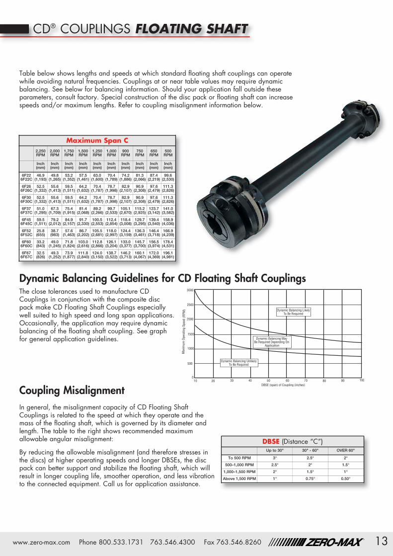
CD® COUPLINGS FLOATING SHAFT
Coupling MisalignmentIn general, the misalignment capacity of CD Floating ShaftCouplings is related to the speed at which they operate and themass of the floating shaft, which is governed by its diameter andlength. The table to the right shows recommended maximumallowable angular misalignment:
By reducing the allowable misalignment (and therefore stresses inthe discs) at higher operating speeds and longer DBSEs, the discpack can better support and stabilize the floating shaft, which willresult in longer coupling life, smoother operation, and less vibrationto the connected equipment. Call us for application assistance.
The close tolerances used to manufacture CDCouplings in conjunction with the composite discpack make CD Floating Shaft Couplings especiallywell suited to high speed and long span applications.Occasionally, the application may require dynamicbalancing of the floating shaft coupling. See graphfor general application guidelines.
Dynamic Balancing Guidelines for CD Floating Shaft Couplings
Table below shows lengths and speeds at which standard floating shaft couplings can operatewhile avoiding natural frequencies. Couplings at or near table values may require dynamicbalancing. See below for balancing information. Should your application fall outside theseparameters, consult factory. Special construction of the disc pack or floating shaft can increasespeeds and/or maximum lengths. Refer to coupling misalignment information below.
Maximum Span C2,250RPM
2,000RPM
1,750RPM
1,500RPM
1,250RPM
1,000RPM
900RPM
750RPM
650RPM
500RPM
Inch(mm)
Inch(mm)
Inch(mm)
Inch(mm)
Inch(mm)
Inch(mm)
Inch(mm)
Inch(mm)
Inch(mm)
Inch(mm)
6F226F22C
46.9(1,193)
49.8(1,265)
53.2(1,352)
57.5(1,461)
63.0(1,600)
70.4(1,789)
74.2(1,886)
81.3(2,066)
87.4(2,219)
99.6(2,530)
6F266F26C
52.5(1,332)
55.6(1,413)
59.5(1,511)
64.2(1,632)
70.4(1,787)
78.7(1,998)
82.9(2,107)
90.9(2,308)
97.6(2,479)
111.3(2,826)
6F306F30C
52.5(1,332)
55.6(1,413)
59.5(1,511)
64.2(1,632)
70.4(1,787)
78.7(1,998)
82.9(2,107)
90.9(2,308)
97.6(2,479)
111.3(2,826)
6F376F37C
51.0(1,295)
67.3(1,709)
75.4(1,915)
81.4(2,068)
89.2(2,266)
99.7(2,533)
105.1(2,670)
115.2(2,925)
123.7(3,142)
141.0(3,582)
6F456F45C
59.5(1,511)
79.2(2,012)
84.9(2,157)
91.7(2,330)
100.5(2,553)
112.4(2,854)
118.4(3,008)
129.7(3,295)
139.4(3,540)
158.9(4,036)
6F526F52C
25.8(655)
38.7(983)
57.6(1,463)
86.7(2,202)
105.5(2,681)
118.0(2,997)
124.4(3,159)
136.3(3,461)
146.4(3,718)
166.9(4,239)
6F606F60C
33.2(843)
49.0(1,245)
71.8(1,824)
103.0(2,616)
112.8(2,866)
126.1(3,204)
133.0(3,377)
145.7(3,700)
156.5(3,974)
178.4(4,531)
6F676F67C
32.5(826)
49.3(1,252)
73.9(1,877)
111.8(2,840)
124.0(3,150)
138.7(3,522)
146.2(3,713)
160.1(4,067)
172.0(4,369)
196.1(4,981)
DBSE (Distance “C”)Up to 30" 30" - 60" OVER 60"
To 500 RPM 3° 2.5° 2°
500–1,000 RPM 2.5° 2° 1.5°
1,000–1,500 RPM 2° 1.5° 1°
Above 1,500 RPM 1° 0.75° 0.50°
14 www.zero-max.com Phone 800.533.1731 763.546.4300 Fax 763.546.8260®
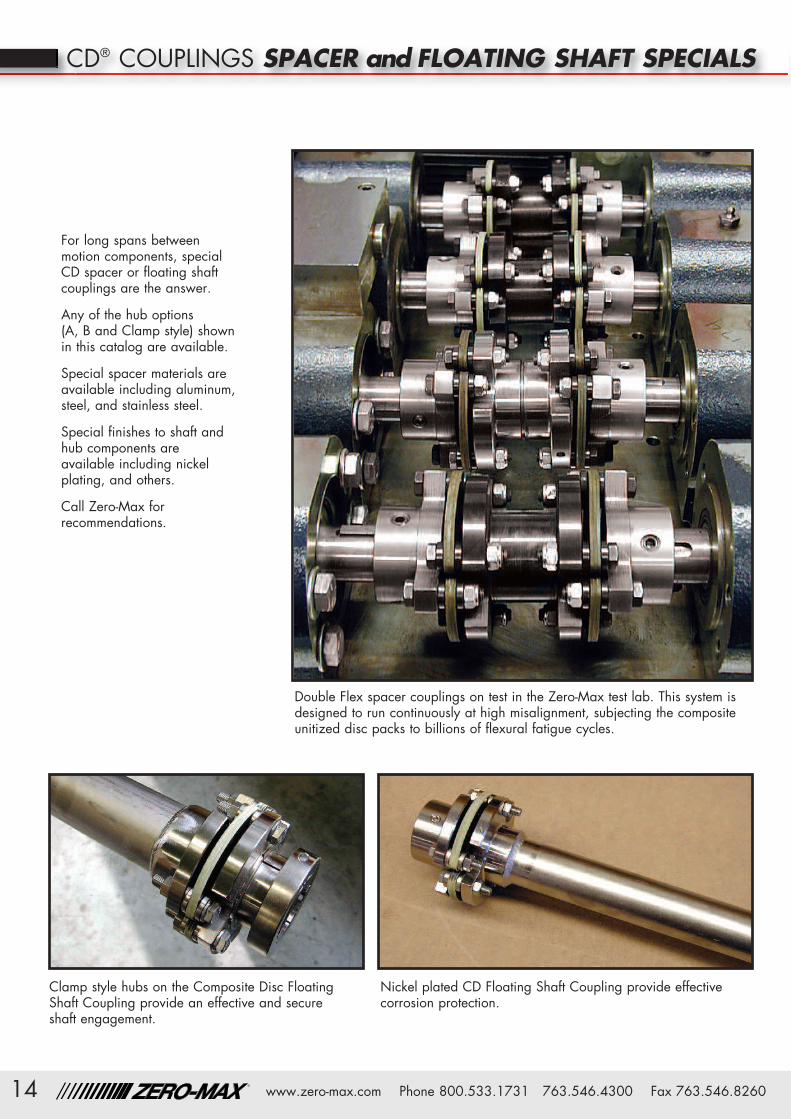
For long spans betweenmotion components, specialCD spacer or floating shaftcouplings are the answer.
Any of the hub options(A, B and Clamp style) shownin this catalog are available.
Special spacer materials areavailable including aluminum,steel, and stainless steel.
Special finishes to shaft andhub components areavailable including nickelplating, and others.
Call Zero-Max forrecommendations.
Double Flex spacer couplings on test in the Zero-Max test lab. This system isdesigned to run continuously at high misalignment, subjecting the compositeunitized disc packs to billions of flexural fatigue cycles.
Clamp style hubs on the Composite Disc FloatingShaft Coupling provide an effective and secureshaft engagement.
Nickel plated CD Floating Shaft Coupling provide effectivecorrosion protection.
CD® COUPLINGS SPACER and FLOATING SHAFT SPECIALS

15www.zero-max.com Phone 800.533.1731 763.546.4300 Fax 763.546.8260®
CD® COUPLINGS SPECIALS
Need higher misalignment and greater torque capacityin your coupling? Need more flexibility and torsionalstiffness too? Need to fit a high performance coupling ina really small space? Need a really large bore diametercoupling or a very long spacer coupling? It is likely thata standard CD Coupling will satisfy your requirements. Ifit doesn’t, we’ll quickly design a solution using our finiteelement analysis (FEA). With experience at thousands ofdifferent applications, our extensive FEA databasebrings instant answers to your questions.
Design, Analysis, Testing Programs, and ProductionCapabilities are all geared toward supplying the correctcoupling at the lowest cost and in the shortest lead time.
The Zero-Max testlaboratory is capable ofall types of static anddynamic testing to insurethat the designspecifications are met.
Production of CDCouplings is executed withmodern CNC machinery,which providescomponents with theaccuracy required fordemanding applications.Quality Control of allmanufacturing processes,guarantees that CDCouplings will meet strictperformance requirements.
Zero-Max is ISO9001:2000 certified.
Custom designs.No application is too large, too small, or too difficultfor a CD coupling. Zero-Max has the ability to provideimaginative solutions for virtually every coupling need.
Design Engineering Assistance.From the first contact you have with our factory trainedand supported Representative, to the completion of theapproval drawing, Zero-Max will provide qualityservice throughout the process. Zero-Max Engineeringis continually involved in custom projects with the latesttechnology available to solve your coupling needs.Our recommendations are based on decades ofcoupling experience.
Finite Element Analysis Tailors Disc to Application.
Using finite element analysis (FEA), the disc design canbe easily modified along with changes in the compositematerial. Custom disc designs (manufactured on state-of-the-art laser cutting machines) can add to or lessencoupling flexibility or increase strength and stiffness asrequired for the particular application. There are over
40 standard models and sizes ofCD couplings for most applications.For applications outside this range,CD Couplings can be designedand produced cost effectivelywithin your delivery requirements.
Key Is The Patented Disc Design.The key to the high performancecapabilities of the CD coupling lies inthe Composite Disc pack. Everythingabout this unique part contributes to itshigh performance characteristics.The shape, the cutting process, thematerial used, the order and the
orientation of the layers, and even the coating used havean important significance.Zero-Max has been perfecting this design since the mid80’s and has accumulated a vast database of solutions.
Coupling Axial Stiffness Test
Full scale durability test of twowind generator couplings underextreme misalignment conditions.

16 www.zero-max.com Phone 800.533.1731 763.546.4300 Fax 763.546.8260®
High Misalignmentand High TorqueComposite materials ofdisc packs offer longer lifeand higher performancethan Stainless disc packs.
High Power in a small spaceThis allowed our customer to usea smaller machine base!
High Misalignmentand High TorqueComposite materials of discpacks offer longer life thanStainless disc packs.
Large ScaleFloating ShaftCouplingsHigh Power WindTurbines requirelong life andsuperior flexibility.
CD® COUPLINGS SPECIALS
Blind Fit CouplingsCoupling is designed so assembly oftwo fixed shafts is possible withoutdisassembly of the components.
Before and After Assembly
QD Bushing CouplingsSingle flex coupling has machinedhub to accept standard QD bushing.
High Speed CouplingsThis coupling uses lowinertia designed hubs forexceptionally high speedapplications.
Shrink Disc Clamping HubsSpecial hubs for high torquekeyless shaft applications.
Phase Adjustable CouplingsSpecial double flex coupling hasbuilt-in phase adjuster for use inprinting presses.
Custom StiffnessCustom Disc pack and hubsto meet critical application.

17www.zero-max.com Phone 800.533.1731 763.546.4300 Fax 763.546.8260®
Aluminum FloatingShaft CouplingsFor high speed operation.
Zero-Max is committed to excellence and completecustomer satisfaction. Every CD custom coupling mustfirst exceed our performance expectations beforeproduction and delivery to you, our customer.
Call today to discuss your customCD Coupling needs 800-533-1731.
Shorter Arm Design YieldsGreater Coupling Rigidity
Longer Arm Design YieldsGreater Coupling Flexibility
Modified Discs For Increased Performance.Nickel Plated CouplingsFor applications requiringfrequent washdowns.
Torque Transducer CouplingSpecial spacer coupling has built-in torquetransducer for use on a test fixture.
Large Scale Floating shaftFor Large scale printing application.Very high torsional stiffness.
Custom Disc PacksTo meet our customer designsand mount directly to customdriveline components
Custom 12 bolt designUltra high torsional stiffness with flexibility.
High Precision in asmall packageDouble flex, clamp hubsonly 1.6" wide!
CD® COUPLINGS SPECIALS

18 www.zero-max.com Phone 800.533.1731 763.546.4300 Fax 763.546.8260®
6. Make sure that the misalignment capability issufficient. As with all couplings, there is a trade-offbetween the parallel, axial and angular misalignmentcapabilities. Be certain that the combined percentagesof each do not exceed 100%. If you have a questionon combined misalignments, consult the factory. It isalways best to select a coupling with misalignmentcapabilities exceeding the initial operating conditionsto allow for changing conditions over the operatinglife of the machine.
7. Check to be sure that the coupling fits the requireddimensions such as available space envelope andbore sizes.
8. If the coupling size and type meet the torque,misalignment, space envelope criteria, the selectionis complete.
Note: If the standard couplings listed in the catalogdo not meet your requirements, please consult thefactory. We will work with you to meet your needs.
1. Select a coupling type (Single Flex, Double Flex,Spacer or Floating Shaft) based on misalignmentand/or DBSE (Distance Between Shaft Ends).
2. Determine the required service factor; please refer tothe chart on the next page.
3. If continuous torque is known, then multiply it by therequired service factor to get the design torque:Design Torque (in-lbs) = Continuous Torque (in-lbs) x ServiceFactorIf continuous torque is not known, but Horsepowerand RPM are, calculate the design torque by usingthis formula:Design Torque (in-lbs) = HP x 63,000 x Service Factor
Coupling RPM4. Select a coupling size that has a continuous torque
rating greater than the Design Torque calculated instep 3. Make sure that the peak torque of theapplication does not exceed the maximum torquerating of the coupling.
5. Check Coupling RPM to be sure it is within the ratedmaximum speed. Consult with factory if your speedexceeds the ratings – We have made many specialcouplings that greatly exceed these ratings.
SELECTING THE RIGHT CD COUPLING
Information Required• Service factor.
• Continuous and peak torque requirements, and/or motor HP.
• Coupling RPM.
• Distance between shaft ends. (DBSE).
• Misalignment requirements.
• Physical space limitations.
• Hub bores, with or without keyways.
• Other environmental considerations.
Selection Procedure
Single Double Floating Shaft Call Factoryfor Customs
19www.zero-max.com Phone 800.533.1731 763.546.4300 Fax 763.546.8260®
Standard KeywaysInch Bore Hubs
Service Factor Guide
The service factors listed are intended only as ageneral guide. For typical service factors used invarious applications, refer to “AGMA Standard-Lcclassification and Service Factors For FlexibleCouplings” (AGMA 514.02).
Standard KeywaysMetric Bore Hubs
Note: Metric bore hubs will be supplied with metricsize setscrews
Bore Tolerances
Based on nominal shaft diameter (AGMA Standard511.02) Clearance Fit Standard. Metric hub bores willbe supplied with H7 clearance fit as standard. S7interference fit available.
Note: Inch bore hubs will be supplied with inchsize setscrews.
Load
Uniform 1.0
Light Shock 1.5
Medium Stock 2.0
Heavy Stock 2.5
Bore SizeKeyway
Bore SizeKeyway
Over To Over To
0.437 0.562 0.125 x 0.062 2.250 2.750 0.625 x 0.312
0.562 0.875 0.187 x 0.094 2.750 3.250 0.750 x 0.375
0.875 1.250 0.250 x 0.125 3.250 3.750 0.875 x 0.437
1.250 1.375 0.312 x 0.156 3.750 4.500 1.000 x 0.500
1.375 1.750 0.375 x 0.187 4.500 5.500 1.250 x 0.625
1.750 2.250 0.500 x 0.250 5.500 6.500 1.500 x 0.750
Bore SizeKeyway
Bore SizeKeyway
Over To Over To
10 12 4 x 1.8 58 65 18 x 4.4
12 17 5 x 2.3 65 75 20 x 4.9
17 22 6 x 2.8 75 85 22 x 5.4
22 30 8 x 3.3 85 95 25 x 5.4
30 38 10 x 3.3 95 110 28 x 6.4
38 44 12 x 3.3 110 130 32 x 7.4
44 50 14 x 3.8 130 150 36 x 8.4
50 58 16 x 4.3 150 170 40 x 9.4
Nominal Bore Tolerance
Shaft Diameter Class 1Clearance Fit
InterferenceFitOver To
0.437 1.500 -0.000 +0.001 -0.001 -0.0005
1.500 2.000 -0.000 +0.001 -0.002 -0.001
2.000 3.000 -0.000 +0.0015 -0.001 -0.001
3.000 4.000 -0.000 +0.0015 -0.003 -0.0015
4.000 5.000 -0.000 +0.002 -0.0035 -0.002
5.000 6.000 -0.000 +0.002 -0.004 -0.0025
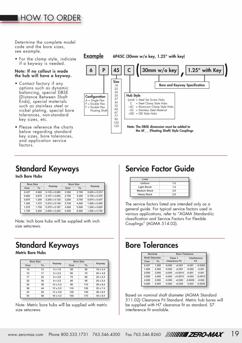
HOW TO ORDER
( , )
Determine the complete modelcode and the bore sizes,see example.
• For the clamp style, indicateif a keyway is needed.
Note: If no callout is madethe hub will have a keyway.
• Contact factory if anyoptions such as dynamicbalancing, special DBSE(Distance Between ShaftEnds), special materialssuch as stainless steel ornickel plating, special boretolerances, non-standardkey sizes, etc.
• Please reference the chartsbelow regarding standardkey sizes, bore tolerances,and application servicefactors.
30mm w/o key 1.25" with Key6 P 45 C
Example 6P45C (30mm w/o key, 1.25" with key)
ConfigurationA = Single FlexP = Double FlexF = Double Flex
Floating Shaft
Bore and Keyway SpecificationSize1822263037455260677790105120
Hub Style(omit) = Steel Set Screw HubsC = Steel Clamp Style Hubs
–AC = Aluminum Clamp Style Hubs–SS = Stainless Steel Material–QD = QD Style Hubs
Note: The DBSE dimension must be added tothe 6F__ (Floating Shaft) Style Couplings

Warranty. Zero-Max, Inc. the manufacturer, warrants that for a period of 12 months from date of shipment it will repair, or at its option, replace any new apparatus which proves defective in material or workmanship, orwhich does not conform to applicable drawings and specifications approved by the manufacturer. All repairs and replacements shall be F.O.B. factory. All claims must be made in writing to the manufacturer. • In no eventand under no circumstances shall manufacturer be liable for (a) damages in shipment; (b) failures or damages due to misuse, abuse, improper installation or abnormal conditions of temperature, dirt, water or corrosives; (c)failures due to operation, intentional or otherwise, above rated capacities, and (d) non-authorized expenses for removal, inspection, transportation, repair or rework. Nor shall manufacturer ever be liable for consequentialand incidental damages, or in any amount greater than the purchase price of the apparatus. • Zero Max, Inc. reserves the right to discontinue models or to change specifications at any time without notice. Nodiscontinuance or change shall create any liability on the part of Zero-Max, Inc. in respect to its products in the hands of customers or products on order not incorporating such changes even though delivered after any suchchange. • This warranty is in LIEU OF ALL OTHER WARRANTIES, EXPRESS OR IMPLIED, INCLUDING (BUT NOT LIMITED TO) ANY IMPLIED WARRANTIES OF MERCHANTABILITY OR FITNESS FOR A PARTICULAR PURPOSE. THETERMS OF THIS WARRANTY CONSTITUTE ALL BUYER’S OR USER’S SOLE AND EXCLUSIVE REMEDY, AND ARE IN LIEU OF ANY RIGHT TO RECOVER FOR NEGLIGENCE, BREACH OF WARRANTY, STRICT TORT LIABILITY OR UPON ANYOTHER THEORY. Any legal proceedings arising out of the sale or use of this apparatus must be commenced within 18 months of the date of purchase. • CAUTION: Rotating equipment must be guarded. Also refer to OSHAspecifications and recommendations. • Zero-Max®, CD®, ETP®, ServoClass®, Torq-Tender®, Control-Flex®, Posi-Lok® and Roh'Lix® are registered trademarks of Zero-Max, Inc. In U.S.A. OHLA™ is a trademark of Zero-Max,Inc. © Zero-Max 2008 Printed in U.S.A.
13200 Sixth Avenue North,Plymouth, Minnesota 55441-5509
Phone: 800-533-1731 (763) 546-4300Fax (763) 546-8260 www.zero-max.com
ServoClass® Couplingswww.zero-max.com/servo
CD®Couplingswww.zero-max.com/cd
Schmidt Offset Couplingswww.zero-max.com/offset
Torq-Tender®www.zero-max.com/torqtender
Control-Flex® Couplingswww.zero-max.com/controlflex
ETP® Bushingswww.zero-max.com/etp
OHLA®Overhung LoadAdapterswww.zero-max.com/ohla
Zero-Max®AdjustableSpeed Driveswww.zero-max.com/drives
Crown Right AngleGear Driveswww.zero-max.com/crown
Roh’lix® Linear Actuatorswww.zero-max.com/rohlix


