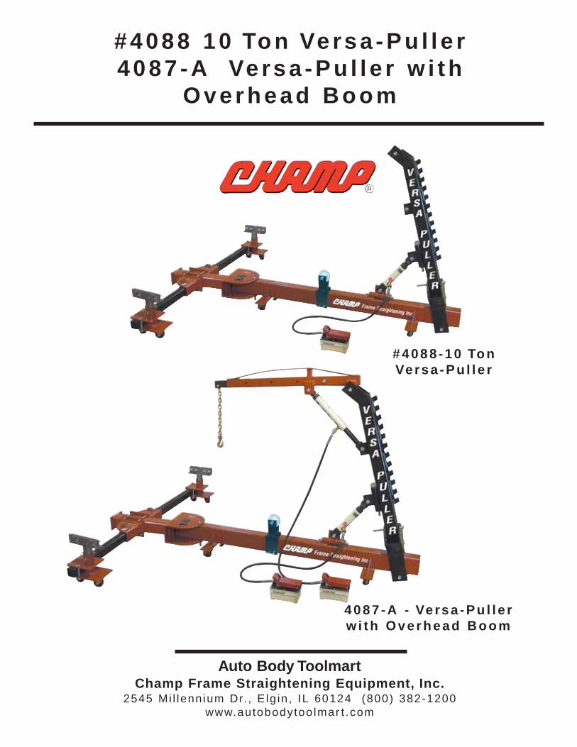
Page 1
Auto Body ToolmartChamp Frame Straightening Equipment, Inc.
2545 Mi l lennium Dr. , E lg in , IL 60124 (800) 382-1200www.autobodytoo lmar t .com
#4088 10 Ton Versa -Pu l l e r4087 -A Ve rsa -Pu l l e r w i th
Overhead Boom
#4088 -10 TonVersa -Pu l l e r
4087 -A - Ve rsa -Pu l l e rw i th Overhead Boom
Page 2
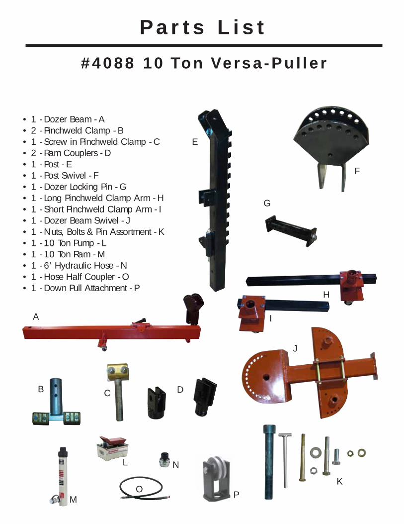
• 1 - Dozer Beam - A• 2 - Pinchweld Clamp - B• 1 - Screw in Pinchweld Clamp - C• 2 - Ram Couplers - D• 1 - Post - E• 1 - Post Swivel - F• 1 - Dozer Locking Pin - G• 1 - Long Pinchweld Clamp Arm - H• 1 - Short Pinchweld Clamp Arm - I• 1 - Dozer Beam Swivel - J• 1 - Nuts, Bolts & Pin Assortment - K • 1 - 10 Ton Pump - L• 1 - 10 Ton Ram - M• 1 - 6’ Hydraulic Hose - N• 1 - Hose Half Coupler - O• 1 - Down Pull Attachment - P
Pa r t s L i s t
A
B D
E
K
C
H
I
F
G
J
L
M
N
O
#4088 10 Ton Versa -Pu l l e r
P
Page 3
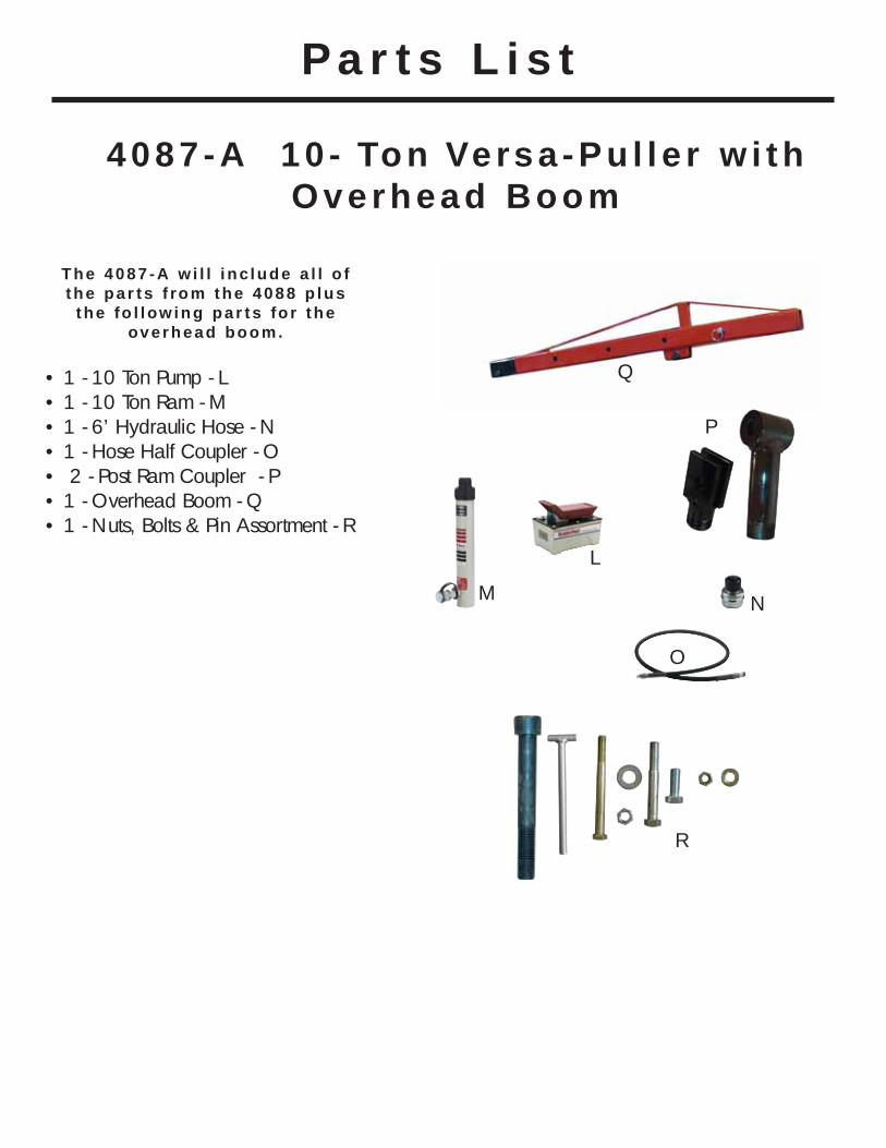
4087 -A 10 - Ton Versa -Pu l l e r w i thOverhead Boom
• 1 - 10 Ton Pump - L• 1 - 10 Ton Ram - M• 1 - 6’ Hydraulic Hose - N• 1 - Hose Half Coupler - O• 2 - Post Ram Coupler - P• 1 - Overhead Boom - Q• 1 - Nuts, Bolts & Pin Assortment - R
Pa r t s L i s t
P
The 4087 -A w i l l i nc lude a l l o fthe pa r ts f rom the 4088 p lus
the fo l low ing par ts fo r theoverhead boom.
L
M N
O
Q
R
Page 4
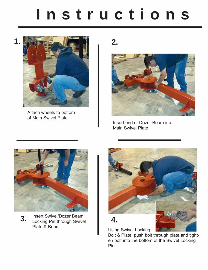
Attach wheels to bottom
of Main Swivel PlateInsert end of Dozer Beam into
Main Swivel Plate
Insert Swivel/Dozer Beam
Locking Pin through Swivel
Plate & BeamUsing Swivel Locking
Bolt & Plate, push bolt through plate and tight-
en bolt into the bottom of the Swivel Locking
Pin.
I n s t r u c t i o n s
1. 2.
3. 4.
Page 5
Dozer Beam is locked into place
using the locking pin. Insert Pinchweld Clamp Swivel Arm into
Main Swivel and lock into place using
locking pin. Arm can be swiveled and
locked into position with second locking
pin. Use the shorter arm on the side of
the car that will be pulled. Repeat on
other side with other Swivel Arm
You should now have the
Versa-Puller Base Assembled.Attach Post Swivel
to end of Dozer
5.6.
7.8.
Page 6
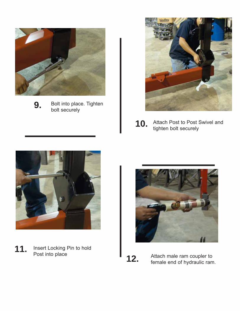
Attach Post to Post Swivel and
tighten bolt securely
Bolt into place. Tighten
bolt securely
Insert Locking Pin to hold
Post into place
9.
10.
11.12. Attach male ram coupler to
female end of hydraulic ram.
Page 7
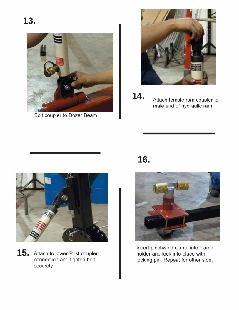
Bolt coupler to Dozer Beam
Attach female ram coupler to
male end of hydraulic ram
13.
14.
15. Attach to lower Post coupler
connection and tighten bolt
securely
16.
Insert pinchweld clamp into clamp
holder and lock into place with
locking pin. Repeat for other side.
Page 8
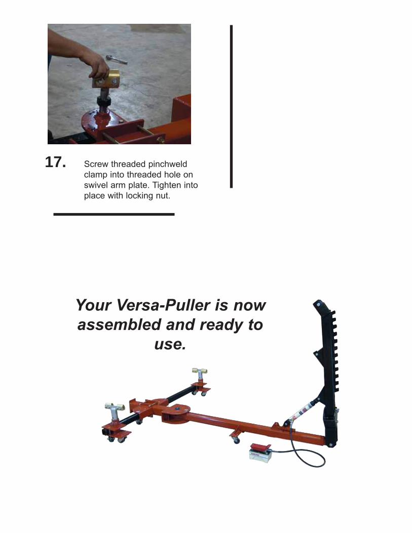
Screw threaded pinchweld
clamp into threaded hole on
swivel arm plate. Tighten into
place with locking nut.
Your Versa-Puller is nowassembled and ready to
use.
17.
Page 9
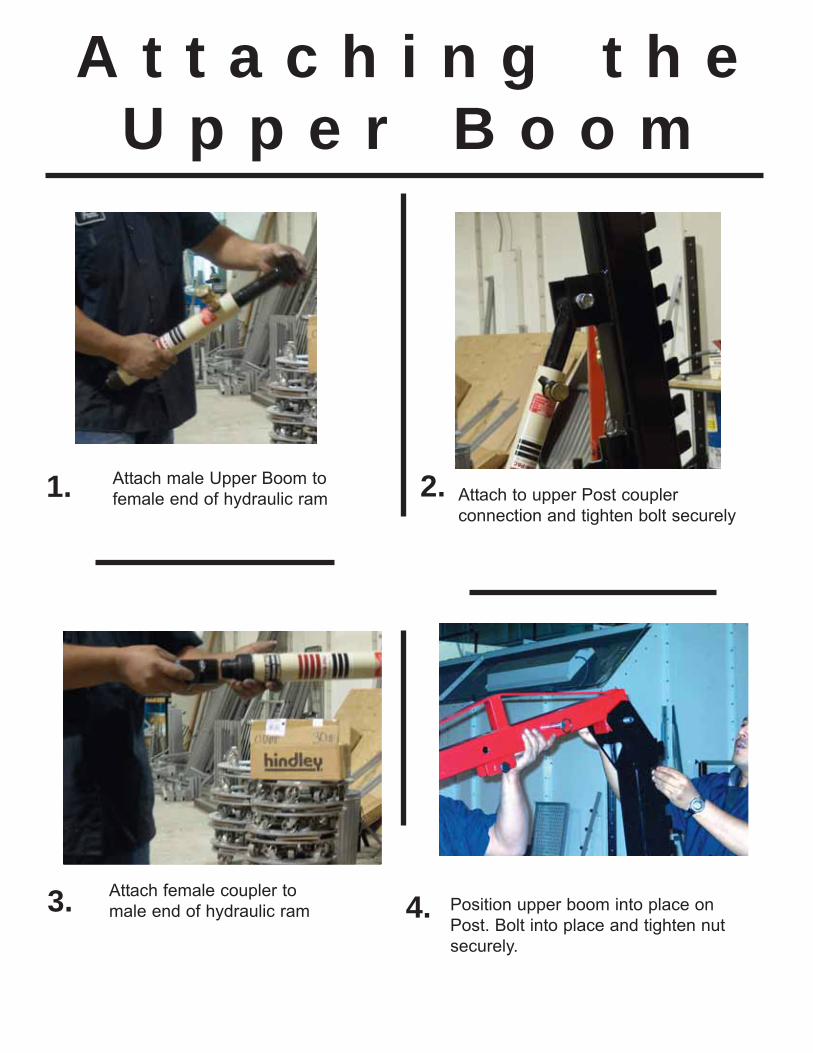
Attach to upper Post coupler
connection and tighten bolt securely
Attach male Upper Boom to
female end of hydraulic ram
Attach female coupler to
male end of hydraulic ram Position upper boom into place on
Post. Bolt into place and tighten nut
securely.
A t t a c h i n g t h eU p p e r B o o m
1. 2.
3. 4.
Page 10
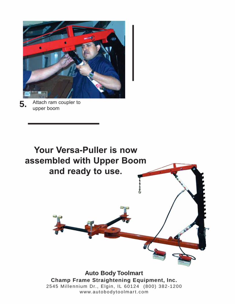
Your Versa-Puller is now
assembled with Upper Boom
and ready to use.
Attach ram coupler to
upper boom5.
Auto Body ToolmartChamp Frame Straightening Equipment, Inc.
2545 Mi l lennium Dr. , E lg in , IL 60124 (800) 382-1200www.autobodytoo lmar t .com
Page 11
4087 Versa -Pu l l e r
Versa-Puller should be completely assembled before using to
familiarize yourself with machine and ensure all components
work properly.
Usag e Ins t ruc t ions
Auto Body ToolmartChamp Frame Straightening Equipment, Inc.
2545 Mi l lennium Dr. , E lg in , IL 60124 (800) 382-1200www.autobodytoo lmar t .com
These instructions will give the basic set-up and pulling
instructions for the Champ Versa-Puller. Set-ups may vary
according to the type of pulling required.
Page 12
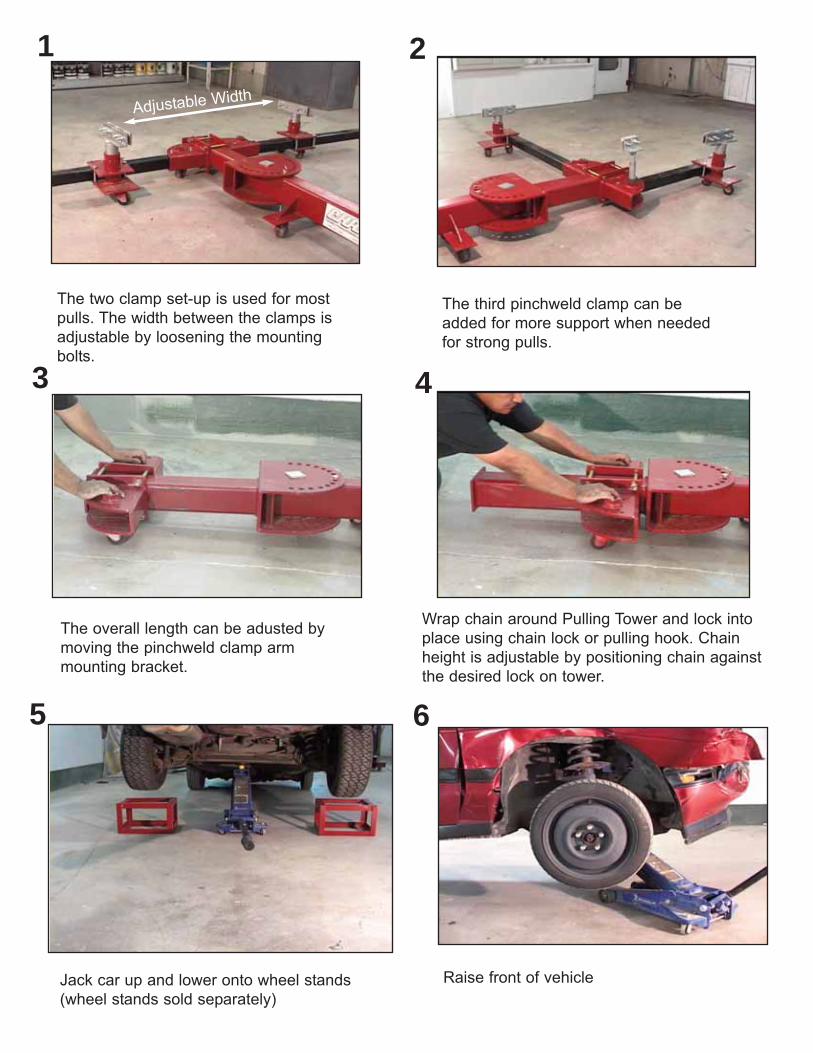
The two clamp set-up is used for most
pulls. The width between the clamps is
adjustable by loosening the mounting
bolts.
The third pinchweld clamp can be
added for more support when needed
for strong pulls.
The overall length can be adusted by
moving the pinchweld clamp arm
mounting bracket.
Wrap chain around Pulling Tower and lock into
place using chain lock or pulling hook. Chain
height is adjustable by positioning chain against
the desired lock on tower.
Jack car up and lower onto wheel stands
(wheel stands sold separately)
4
Adjustable Width
Raise front of vehicle
65
3
21
Page 13
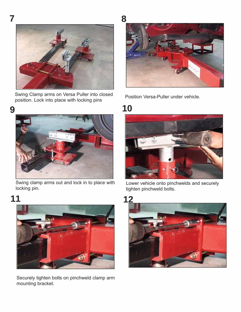
Swing Clamp arms on Versa Puller into closed
position. Lock into place with locking pinsPosition Versa-Puller under vehicle.
Swing clamp arms out and lock in to place with
locking pin.Lower vehicle onto pinchwelds and securely
tighten pinchweld bolts.
Securely tighten bolts on pinchweld clamp arm
mounting bracket.
1211
109
87
Page 14
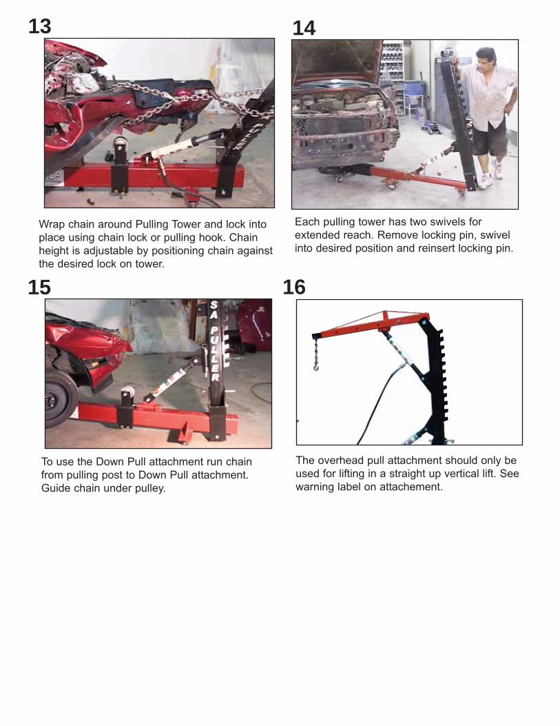
Wrap chain around Pulling Tower and lock into
place using chain lock or pulling hook. Chain
height is adjustable by positioning chain against
the desired lock on tower.
Each pulling tower has two swivels for
extended reach. Remove locking pin, swivel
into desired position and reinsert locking pin.
1413
To use the Down Pull attachment run chain
from pulling post to Down Pull attachment.
Guide chain under pulley.
15 16
The overhead pull attachment should only be
used for lifting in a straight up vertical lift. See
warning label on attachement.