16
1 4 th PV Performance Modeling Collaborative Workshop Modelling of bifacial PV modules Gianluca Corbellini Vasco Medici
| Date post: | 12-Apr-2017 |
| Category: |
Presentations & Public Speaking |
| Upload: | sandia-national-laboratories-energy-climate-renewables |
| View: | 461 times |
| Download: | 0 times |
1 4th PV Performance Modeling Collaborative Workshop
Modelling of bifacial PV modules
Gianluca Corbellini
Vasco Medici
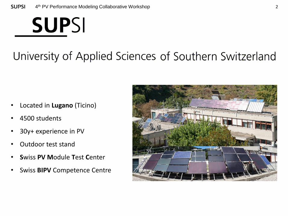
2 4th PV Performance Modeling Collaborative Workshop
• Located in Lugano (Ticino)
• 4500 students
• 30y+ experience in PV
• Outdoor test stand
• Swiss PV Module Test Center
• Swiss BIPV Competence Centre

3 4th PV Performance Modeling Collaborative Workshop
Agenda
• Outdoor measurement
• Modelling
• Indoor measurement
• Fit of parameters
• Results of modelling
• Conclusions and next steps

4 4th PV Performance Modeling Collaborative Workshop
Outdoor measurement Testing of outdoor performance for 12 PV modules between June 2014 and June 2015
Orientation: 45° tilt at 3°E azimuth
Location: Lugano (south Switzerland)
Sensors: GHI, DHI, front GPOA , back GPOA , TBOM monofacial
All modules operating at MPP, I-V curve measurement every 5 minutes
Technology ɳ @STC γ (%/°C) ɳ @200W/m2
HJT BIFAC 1 18.6% -0.33% 3.1%
HJT BIFAC 2 17.7% -0.26% 3.1%
HJT BIFAC 3 17.6% -0.28% 2.3%
C-Si 1 16% -0.41% 5.1%
C-Si 2 15.9% -0.41% 5.1%
HJT MONO 1 19.4% -0.26% 4.9%
HJT MONO 2 19.4% -0.26% 4.9%
CIS 1 13.8% -0.34% 5.4%
CIS 2 13.7% -0.34% 5.4%
C-Si 3 13.4% -0.43% 2.4%
CdTe 1 10.9% -0.25% 0.5%
CdTe 2 10.6% -0.25% 0.5%

5 4th PV Performance Modeling Collaborative Workshop
Outdoor bifacial vs monofacial
All day types Overcast
PR ΔkWh/kWp PR ΔkWh/kWp
HJT BIFAC 3 101% 13.7% 106% 15.4%
HJT BIFAC 2 100% 12.5% 105% 13.9%
HJT BIFAC 1 99% 11.8% 104% 13.7%
CIS 1 97% 9.0% 95% 3.8%
CIS 2 96% 7.7% 97% 5.4%
CdTe 2 95% 7.0% 98% 6.5%
CdTe 1 94% 5.6% 94% 1.9%
c-Si 3 92% 3.4% 98% 6.4%
HJT MONO1 92% 2.9% 92% 0.2%
HJT MONO2 91% 2.2% 91% 0.1%
c-Si 1 90% 0.7% 93% 0.9%
c-Si 2 89% Ref. 92% Ref.
Bifacial modules show and additional 10 to 13% energy yield with respect to
monofacial HJT
Strong dependence on sky conditions (diffuse/direct ratio) and position of the sun
HJT Bifacial 2 vs HJT Mono 1 in clear sky days

6 4th PV Performance Modeling Collaborative Workshop
Modelling of Irradiation
SKY DIFFUSE RADIATION
DIRECT RADIATION
GROUND REFLECTED GROUND REFLECTED
COMPARISON OF 5 MODELS

7 4th PV Performance Modeling Collaborative Workshop
Modelling of Performance
LOW IRRADIANCE TERM CORRECTED FLASH TEST TEMPERATURE TERM
Tbom estimated from VOC and ISC
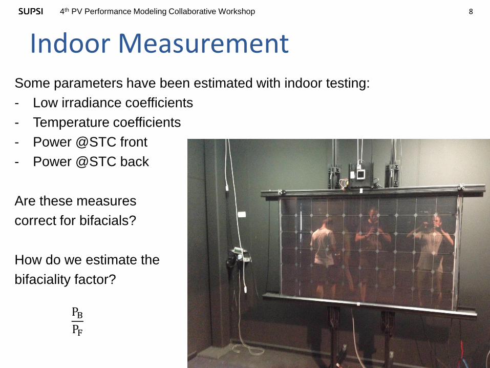
8 4th PV Performance Modeling Collaborative Workshop
Indoor Measurement Some parameters have been estimated with indoor testing:
- Low irradiance coefficients
- Temperature coefficients
- Power @STC front
- Power @STC back
Are these measures
correct for bifacials?
How do we estimate the
bifaciality factor?
PBPF

9 4th PV Performance Modeling Collaborative Workshop
Indoor Measurement
Comparison of front reference cell and a cell on the backside at
different position
1.09 0.44 0.48 1.12
1.1 0.58 0.48 0.82
1.11 0.56 0.52 0.51 0.93
5%
φ ≈ 0.0044
PF = PF +φPBPB = PB + φPF
PF = 291.74 W PF = 𝟐𝟗𝟎. 𝟓𝟕 W
PB = 261.61 W PB = 𝟐𝟔𝟎. 𝟑𝟎 W
Measure of reflections on the backside in the dark room [%]:
Bifaciality factor = 0.896 Corrected for JB = 0.948

10 4th PV Performance Modeling Collaborative Workshop
Modelling of TCELL
Cell temperature estimated from a one-diode model tuned using indoor data
Validation on 1 year outdoor data of a standard module (framed poly-Si 260W)
IPH
IS RS
RSH
ISH
V
+
-
ISC VOC
TCELL
α
β
Rsh (G)
TMODEL = 0.982 TMEAS + 0.748
RMSE = 0.4535

11 4th PV Performance Modeling Collaborative Workshop
Modelling of TCELL
Validation on a standard module
(framed poly-Si 260W)
TCELL modelled RMSE = 0.4535
IPH
IS RS
RSH
ISH
V
+
-
ISC VOC
TCELL
α
β
Rsh (G)
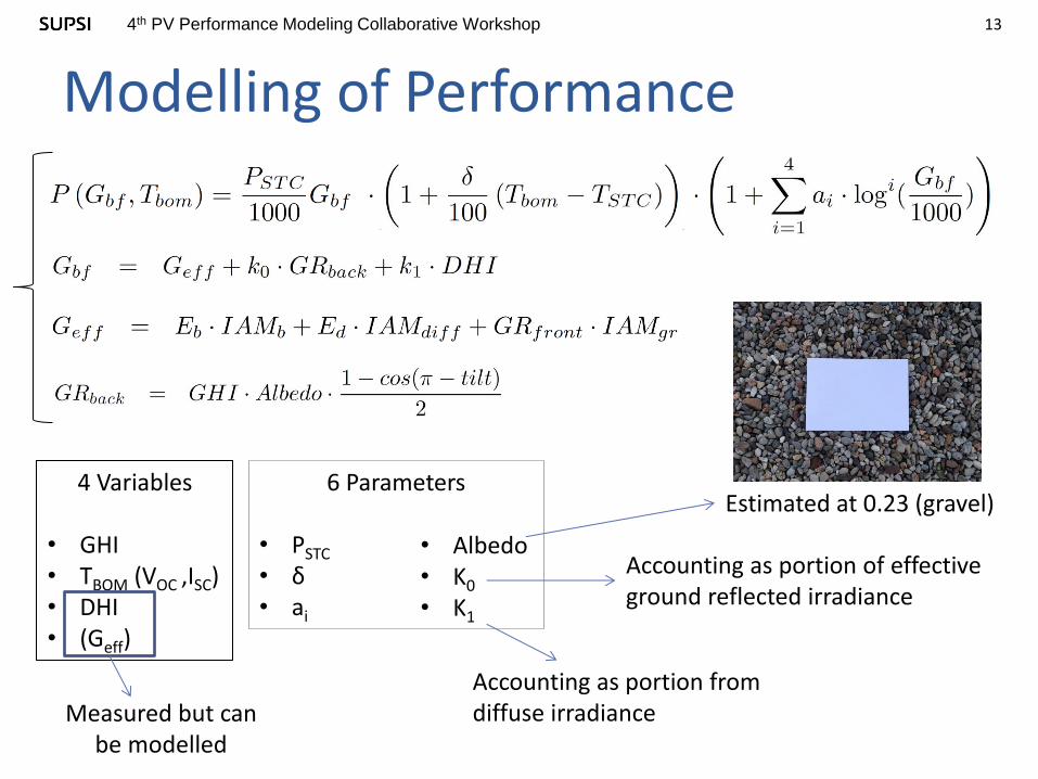
13 4th PV Performance Modeling Collaborative Workshop
Modelling of Performance
4 Variables
• GHI • TBOM (VOC ,ISC) • DHI • (Geff)
6 Parameters • PSTC • δ • ai
• Albedo • K0
• K1
Accounting as portion of effective ground reflected irradiance
Accounting as portion from diffuse irradiance Measured but can
be modelled
Estimated at 0.23 (gravel)
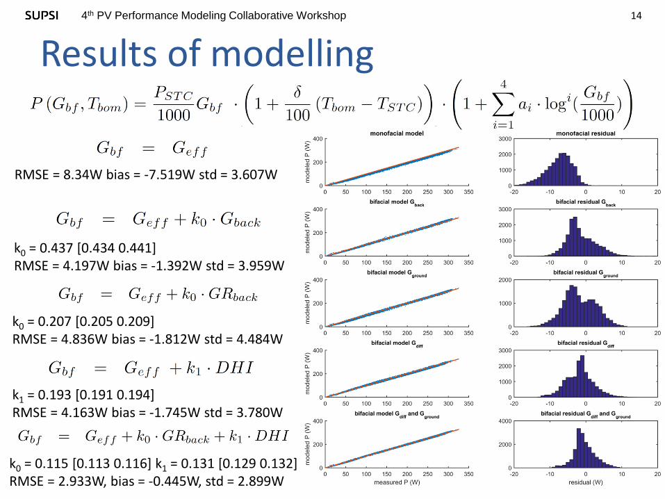
14 4th PV Performance Modeling Collaborative Workshop
Results of modelling
RMSE = 8.34W bias = -7.519W std = 3.607W
k1 = 0.193 [0.191 0.194] RMSE = 4.163W bias = -1.745W std = 3.780W
k0 = 0.437 [0.434 0.441] RMSE = 4.197W bias = -1.392W std = 3.959W
k0 = 0.115 [0.113 0.116] k1 = 0.131 [0.129 0.132] RMSE = 2.933W, bias = -0.445W, std = 2.899W
k0 = 0.207 [0.205 0.209] RMSE = 4.836W bias = -1.812W std = 4.484W

15 4th PV Performance Modeling Collaborative Workshop
Conclusions
Two parameters model covers very well the backside
contribution to module’s power, both terms are significant
Reflections in dark room need to be taken in account
TCELL(VOC, ISC) is very accurate on monofacials and
promising for bifacials

16 4th PV Performance Modeling Collaborative Workshop
Next Step
Improve TCELL(GBF, TAMB) modelling, only from environmental
variables
Testing of different tilt/azimuth – optimization for climates
New standard procedure for nameplate power definition and
indoor testing
Modelling of LCOE as the key factor for bifacial success

17 4th PV Performance Modeling Collaborative Workshop
Thank you for your kind attention
Thank you for your kind attention
Gianluca Corbellini - SUPSI


