Page 1
1 /43
4.1 Final publishable summary report
Executive summary.
The HIMMOVAL project aimed to develop a new rapid metal removal concept under acceptable
surface integrity constraints for fabricating typical jet engine components made of heat resistant
superalloys. The concepts will be based on smart use of conventional machining technologies,
software for simulations to support decision-making and analysis of the feasibility of non-
conventional machining technologies and their effect on part integrity. HIMMOVAL aims at
optimised conventional machining operations and a well-defined sequence of processes for
manufacturing.
The developed concept showed high productivity, low cost, the capability to create special
geometries or cavities and the robustness to be translated to a real production situation. The
feasibility of a radical improvement of material removal rate when using conventional machining
with defined cutting edges through cryogenic cooling and creative machining strategies was also
explored.
The generated results enabled optimum selection of removal processes together with their parameters
under stringent surface integrity requirements for heat resistant superalloys. Moreover, the rapid
removal concept contributed to delivery of technologies addressed for the open rotor demonstrator
within the CSJU SAGE2 project.
º
The HIMMOVAL consortium is integrated by:
Aeronautic Industry (Topic Manager) - GKN Aerospace
Sweden
Research organisation (Coordinator) - Tecnalia R&I
Spain
University of Basque Country UPV\EHU -
Spain
Small-Medium Enterprise - GeonX
Belgium
Page 2
2 /43
SUMMARY DESCRIPTION OF PROJECT CONTEXT AND OBJECTIVES
The number of aircraft will increase greatly over the next 20 years, according to the Airbus Global
Market Forecast (AGMF). Regarding the increase of aircraft (3.7% per year) resulting from the
growth of air traffic (4.7% per year), by 2034 it is estimated that more than 38.000 aircrafts will be in
service. Of these, 19,000 are necessary due to growth, whereas 13,000 will be replacements of actual
airplanes, leading to 32,000 new aircraft which need to be built.
-
- Figure 1. Estimation of aircraft up to 2034 (Airbus Global Market Forecast (2015-2034))
This leads to a significantly increasing necessity of manufacturing high-temperature resistant
materials used in the turbo-machinery. Superalloys used in aerospace, such as Nickel base and
Titanium alloys, are usually employed because of their unique combination of properties like high
strength at elevated temperatures, resistance to chemical degradation and wear resistance.
The HIMMOVAL project aims to:
1) For conventional machining methods: develop new knowledge about the properties of Ni-
based alloys (Alloy 718, Waspaloy and Haynes 282)
2) For non-conventional machining methods: analyse the properties of one of the Ni-based
alloys when using the following methods:
a. Wire Electron Discharge Machining (WEDM)
b. Abrasive Waterjet (AWJ)
c. Laser Beam (LB)
d. Ultrasonic Vibration Assisted Milling (UVAM)
Page 3
3 /43
Conventional Machining Methods
Regarding the conventional machining, HIMMOVAL project generated and developed new
knowledge in Ni-based alloys (Alloy 718, Waspaloy and Haynes 282), which took into account heat
treatment procedures, metallurgical characterisation, machinability tests and the effect of different
cooling strategies in machining and in tool behaviour.
In this context, two demonstrators were delivered:
A) Hardware demonstrator: optimisation of manufacturing sequence taking into account
initial stress map of raw material.
Different aspects must be controlled during production of high value components. In conventional
machining, a major problem is the geometrical distortion obtained after the machining of the final
workpiece. Although the project is focusing on Ni-based alloys, this demonstrator was performed in
Aluminium 7075 since it is less expensive and provides similar properties for the simulation.
For the simulation, it is necessary to know the initial stress map of the raw material, sequence of
manufacturing and clamping system used. It is important to note that force and temperature
generated during interaction were not integrated in the global model.
Figure 2. Demonstrator in Aluminium 7075.
B) Software component: machinability database for Heat Resistant Superalloys.
Alloy 718, Waspaloy and Haynes 282 were studied during the project. Aspects considered during
experimentation were:
Different states (Aged and Solution treated)
Grain Size (Small and Large grain)
Normal cooling tested (6bar) and High Pressure Cooling tested (80bar): including the
observed effects on tool wear
As results of the experimentation, a high quantity of data has been generated and recorded. A
database, with a special visualisation tool (web platform), has been developed to facilitate the
comparison between different parameters of the machining process, such as the cooling system,
different alloys and influence of properties in the tool wear life.
Page 4
4 /43
Figure 3. HIMMOVAL software.
Non-conventional machining methods
The selected alloy used in non-conventional machining methods was Alloy 718, mainly due to the
fact it is currently the most used material for jet engine components and its mechanical properties
were verified during the conventional machining methods analysis. Alloy 718 was developed to
work in high temperature conditions while keeping its mechanical properties.
This alloy was tested using the four non-conventional methods (see above) and measured in terms of:
o surface measurements
o Scanning Electron Microscope (SEM) characterisation
o fatigue test campaign
These results were compared to conventional methods.
In addition, LPB (Low Plasticity Burnishing) as a post-processing method was applied to WEDM, LB
and UVAM and has shown to increase surface hardness of the material. Moreover, PWJ (Pure
Waterjet) as a post-processing method was applied to specimens previously machining with AWJ and
it has proven to be able to remove abrasive particles embedded in the material.
In this context, two demonstrators were delivered:
A) Hardware demonstrator: cutting and machining operations in Alloy 718 using non-
conventional machining methods.
Due to the availability of resources, only AWJ technology was used.
In order to evaluate the milling capabilities of AWJ technology, an extended flange feature including
a hole to “emulate” a fastener has been manufactured in Alloy 718. Figure 4, obtained in a standard
AWJ machine, shows capabilities of AWJ technology for cutting and milling in the same component.
Page 5
5 /43
Figure 4. AWJ demonstrator over Alloy 718.
B) Software demonstrator: Modelling of non-conventional machining methods during
machining of Nickel based material.
Figure 3. Software developed for AWJ technology.
Non-conventional machining methods, namely Laser or AWJ show some error due to the process
non-rigid cutting tool (the beam). In the case of AWJ technology, two main known errors are taper
angle and lead angle, which are directly related to the process parameters and the material to be cut.
During HIMMOVAL project, specific software has been developed based on the experimental test
done in Alloy 718 using AWJ technology.
These non-conventional machining methods showed benefits not only in terms of operational
costs but also capability in terms of creating special geometries or cavities including
demonstrated robustness. It will be possible to translate these technologies into a real production
situation provided that the design of the machines is performed.
Page 6
6 /43
DESCRIPTION OF THE MAIN S&T RESULTS/FOREGROUND
WP2. Rapid removal concept generation
This work package was devoted to generate the rapid material removal concept for typical jet engine
components made of HRSA.
T2.1. Definition of concepts for rapid material removal of super alloys components
Excel-based cost models have been developed for each of the non-conventional technologies (AWJ,
LB and WEDM) for the evaluation of costs for a specific machining program. Figure 4 shows an
example for the AWJ technology. Similar tables have been developed for LM and WEDM. These
models, together with the database developed within WP4 with process parameters, allow evaluating
and comparing the costs between different processes and thus, selecting the best technology selection
for different machining parts.
Feed rate, v [mm/min] 125
Orifice diamenter, d n [mm] 0,25
Pressure, p [MPa] 350
Abrasive mass flow rate, m a [g/min] 250
Cutting length [mm] 100
Depreciation
Initial cost, I [€] 280000
Depreciation period, D [years] 7 Cd = I/(D*La) 20 €/h
Machine utilization, L a [h/year] 2000
Electrical power cost
Electrical power consumption (entire system), E [kW] 0,02 Ce =c e* E 0,0024 €/h
Electricity cost, c e [€/kWh] 0,12
Maintenance Cost
Maintenance Cost per year, M [€/year] 10000
Cutting and Cooling water Cost
Cutting water consumption, m w [l/min] 1,73
Cooling water consumption, W [l/min] 1,00 C w = 60*c w*(m w +W) 0,08 €/h
Water price, c w [€/l] 0,001
Cost of abrasive
Abrasive consumption, m a [kg/min] 0,25 C a = 60*c a*ma
Abrasivo price, c a [€/kg] 0,35
Costs of replacement and wearing parts
Orifice price, c n [€/part] 3000
Orifice lifetime, L n [h/part] 1000
Focusing tube price, c m [€/part] 95
Focusing tube lifetime, L m [h/part] 75
Mixing chamber part, ck [€/part] 150
Mixing chamber lifetime, Lk [h/part] 400
Operator cost 22 C o 22 €/h
€/h
PROCESS COST
14,98
C=CT*t 0,76 €
C r = C n + C m = c n/L n +c m/L m+ck/Lk 4,64 €/h
57
€/h5,00
Fixed Costs
Variable Costs
5,25
TOTAL COST
CUTTING PARAMETERS
€/h
OPERATION COST
CT = Cd + Ce+ Cm + Cw + Ca + Cr + Co €/h
CT = Ce+ Cm + Cw + Ca + Cr
Cm = M/L a
AWJ PROCESS COST MODEL
Figure 4. Example of the AWJ Process Cost Model developed in HIMMOVAL project
In addition, based on the simplified design element proposed on the CfP, 5 different rapid removal
concepts for the manufacturing of a typical jet engine component have been defined, showed in
Table 1.
Page 7
7 /43
Table 1. An example of rapid removal concept
Rank Manufacturing sequence Concept hurdles
1
1.1 Rough peripheral material removal using
AWJ cutting
- Clamping sequence
- Process parameters and cutting strategies
for deep cutting
1.2 Cutting by AWJ of the strut hollow
- Process parameters and cutting strategies
for deep cutting of HRSA materials
- Cutting quality for deep cutting of HRSA
materials
1.3 Particle removal from the strut hollow surface
by PWJ (if required)
- Removal strategy in difficult to access
surfaces
1.4 Semi-finishing of the strut surface by
conventional machining
1.5 Finishing of the strut surface using LPB - Small fillet radius
2
2.1 Rough peripheral material removal using
AWJ milling
- Small tool radius
- Process parameters for deep milling of
HRSA materials
- Online control of milled depth
- Rough surface
- Abrasive embedment
2.2 Cutting by AWJ of the strut hollow - Cutting strategies for deep cutting of
HRSA materials
2.3 Particle removal from the strut hollow surface
by PWJ (if required)
- Particle removal
- Small tool radius
2.4 Semi-finishing of the strut surface by
conventional machining
2.5 Finishing of the strut surface using LPB Same as 1.5
3
3.1 Rough peripheral material removal using
AWJ cutting Same as 1.1
3.2 Cutting by AWJ of the strut hollow Same as 1.2
3.3 Particle removal from the strut hollow surface
by PWJ (if required) Same as 1.3
3.4 Semi-finishing of the strut surface by
conventional machining
3.5 Finishing of the strut surface by grinding - Surface burns
- Wheel shape
4
4.1 Rough peripheral material removal using
AWJ milling Same as 2.1
4.2 Cutting by AWJ of the strut hollow Same as 2.2
4.3 Particle removal from the strut hollow surface
by PWJ (if required) Same as 2.3
4.4 Semi-finishing of the strut surface by
conventional machining
4.5 Finishing of the strut surface by grinding Same as 3.5
5
5.1 Peripheral roughing by plunge milling
5.2. Semi-finishing of the strut surface by slice
and trochoidal milling
5.3 Plunge plus trochoidal milling of the strut
hollow with relieved shank milling tool
5.4 Finishing of the strut surface by LPB
Page 8
8 /43
Figure 5. First rapid removal concept of Table 1.
During Himmoval project, Abrasive WaterJet (AWJ) technology was developed in two different
ways. First of them, it has been in its current used in the industry, it means, only for cutting through
material and second way developed, as Abrasive WaterJet milling, novelty applications for WaterJet.
In previous, Table 1, two different sequences are proposed, based on capabilities of the WaterJet
technology. Rank number 1, is proposed using WJ as cutting technology and Rank number 2, is
proposed WJ as milling technology.
T2.2 Work planning for machining and surface removal tests
In this task experimental tests were defined for conventional and non-conventional machining
methods(AWJ, LB and WEDM).
Conventional Machining Methods
Tests in 3 different HRSA (Alloy 718, Waspaloy and Haynes 282) and at 4 different material
conditions (fine grain solution annealed, fine grain precipitation hardened, coarse grain solution
annealed and coarse grain precipitation hardened) were defined for transverse turning processes.
Machining tests consisted on face turning tests to avoid the hardness influence of the different layers
that can appear on a longitudinal turning. It is normal when an alloy bar is heat treated, to have a
heterogeneous structure from the surface to the core of the material, being the most internal part of
the material in a softer condition because of difficulties of the heat treatment to reach all material
points. So, in longitudinal turning, as the bar is being machined and tool reaches inner points, turning
tests are not completely comparable. In face turning, all tests are comparable, and similar
independently of the longitudinal position of the tool.
Defined face turning test consisted of 6 facing passes, being the depth of cut of 2 mm, so a total
thickness of 12 mm disk would be machined on each test. The cutting speed was 30 m/min, and the
feed was 0.1mm/rev, so that for each pass a total spiral length of 121 meters would be machined,
machining each insert tool a total length of 727 meters approximately.
Face turning tests were defined to carry out in a CNC lathe CMZ model TC25BTY. Two different
cooling strategies were defined: conventional cooling at 6 bar, and High Pressure Cooling with an
independent pump of 80 bar pressure and 40 l/min flowrate
The results measurement procedures and data acquisition systems were defined, which consisted on:
Process force measurement by Kistler 9257B dynamometer system
Rough peripheral
AWJ Cutting
Strut hollow cutting by
AWJ
Particle removal by
PWJ
Semifinishing by conventional
machining
Finishing by LBP
Page 9
9 /43
Tool wear measurement by 2 cameras integrated into the turning center, so the tool is never
removed for analysis.
Micro-hardness measurement by hardness Vickers indentations
Residual stresses measurements by hole drilling method
Roughness measurements by Taylor Hobson Surtronic DUO portable surface roughness
instrument
Figure 6. Top: force acquisition set-up. Bottom left: microscope cameras for in-process wear measurement; Bottom right:
hole drilling method
Alternative cryogenic turning set-up was prepared for testing materials with this increasingly used
technology for cooling/lubrication. Special CO2 equipment with a prepared nozzle was intended to
be used, with fully programmable functions for testing various adjustments in accordance with the
lathe face turning programmes.
In accordance with previous published literature, it is very important to reach the cutting zone in a
proper way with the cooling fluid, which implies the testing of several nozzle dispositions in terms of
angular orientation, and distance to the cutting zone.
Depending on obtained results, an additional approach was intended, with a system prototype of
three channels, were the inner one is reserved for oil transport, the middle one with pressurized air,
and the external one the cooling agent CO2.
Simulation of process
In order to predict distortions during machining, information needed from experimental machining
tests were listed:
Page 10
10 /43
Geometry of the ingot
Initial stress state in the laminated ingot
Lamination direction
Clamping system configuration and sequence
Machining regime and sequence
Intermediate geometries of each machining sequence
Figure 7. Process Simulation
Non-conventional machining methods
According to the interests defined by the topic manager, experimental tests were defined for cutting
Alloy 718 by AWJ, LB and WEDM technologies. In addition, tests were defined for post-processing
by PWJ and LPB treatments.
WP3. Material properties, testing and produceability
In this work package materials for machining tests defined in WP2 were selected and prepared.
A very relevant issue within this work package consisted on preparing test parts to the adequate
geometry and conditions in order to make the results compatible with those obtained by the topic
manager from previous investigations and experimental work. Test parts were heat treated to achieve
the requested conditions in terms of grain size and hardness.
Within this work package, all other materials and equipment to be used during the machining tests
were also selected and prepared. This includes the setting up machines, fixtures and other equipment
(e.g. sensors, acquisition boards, part/tool measuring devices), procurement of cutting tools or
creation of templates for data recording.
T3.1 Materials selecting and preparing
For experimental tests, Alloy 718, Waspaloy and Haynes 282 with small and large grain size, both
solution treated and precipitation hardened were obtained. Thus, 4 different material microstructures
were obtained: Small Grain Solutioned (SGS), Small Grain Aged (SGA), Large Grain Solutioned
(LGS) and Large Grain Aged (LGA). Analysis regarding the heat treatment curves, crystallographic
microstructure, grain size and hardness state were done.
Page 11
11 /43
Figure 8. Alloy718. left: Small grain (solution treated); right: small grain (precipitation hardened)
Figure 9. Alloy 718: left: Large grain (solution treated); right: Large grain (precipitation hardened)
Similar curves from Figure 8 and Figure 9 were obtained for the other 2 HRSA.
One single batch from each material was used for all tests to prevent any additional effect from
chemistry or metallurgical variations.
Next figure shows different chemical compositions of the materials used in HIMMOVAL project.
Table 2. Chemical composition of materials Alloy 718, Waspaloy and Haynes 282 used for experimentation.
Grain size and hardness were measured in each alloy after the application of the heat treatments.
Page 12
12 /43
Table 3. Grain size and hardness of Alloy 718, Waspaloy and Haynes 282 for different Heat treatments
For experimental tests, acquirement and measuring procedures defined in T2.2 have been integrated,
e.g., k-type thermocouples have been placed into carbide inserts by EDMed holes for process
temperature measurement:
Figure 10. Drilling tests in Sandvik inserts and tool design for drilling blind holes in tool TCMW16T304
T3.2 Practical machining for produceability testing
Experimental set-up
In order to validate the procedure of performing turning tests in HRSA, firstly, tests were carried out
in Aluminum alloy 7075-T6. These first tests allowed setting up the CNC programs, measuring
systems, and verifying the aptitude of the holed turning inserts.
Figure 11. left: Forces results; right: Temperature results
Figure 12. Insert wear
Page 13
13 /43
Figure 13. left: Roughness results for one single test; right: Chip formation and shape
After validating the procedure in Aluminum alloy, face turning tests defined in T2.2 were carried out
in the 3 HRSA materials. A CMZ TC25BTY Turning Center was used during experimentation.
In addition, during this task a new set of tests were run during the project using High Pressure
Cooling (HPC) instead normal cooling, with the aim of reducing the tool wear. Face turning (along
X-axis) was carried out on a CMZ TC25BTY lathe applying cutting fluid, in this case Houghton
Hocut B 750 a mineral oil-based emulsion diluted in water to 12% solution. For the tests resembling
a conventional coolant application the pressure used is 6 bar, while the pressure is raised to 80 bar for
the high pressure cooling tests.
Figure 14. Left: Machining Test Set-up, Right: HPC set-up.
Face turning was chosen to keep uniformity between any of the experiments; heat treatment always
causes a spread of hardness along rod radius, due to the difficulties of heating/cooling the rod core.
Cylindrical turning test would be affected for this change at each workpiece radius and as
consequence at each tool pass, whereas face turning it introduces a hardness variation in every pass
from the outer to the inner radius, but it is always the same
For the HPC tests, the tool holder (reference Sandvik STFCR 25x25M 16) was deeply modified to
supply high pressure cooling into the cutting area, because it is not possible to obtain a commercial
solution for HPC face turning, and it was fundamental to maintain comparable tests conventional and
HPC cooling face turning tests. Jets must be oriented to relief and rake faces of the primary cutting
edge, but in face turning primary edge is the secondary edge of cylindrical turning. To do that,
Page 14
14 /43
nozzles of 0.8 mm were installed onto tool holder to impact directly in the desired points (Figure 15).
One nozzle was used in the relief face, and two nozzles were used in the rake face.
To allow measurement of the temperature during the cutting operation, holes were drilled in the tool
insert to introduce two thermocouples close to the cutting zone. To avoid possible perturbations on
the thermal transmission due to sensor installation, holes of 0.3 mm in diameter and 3.67 mm depth
were machined using an especially designed EDM micropin for this purpose. The depth of the holes
was controlled through the CNC machine and measured by a microscope on the cross-section face to
ensure the position of the sensor tip.
Figure 15. a) Tool insert with EDMed holes. Detail. b) Toolholder preparation for HPC tests and temperature
measurement.
Wear was measured using two computer microscopes mounted in a specific tooling to avoid
unbolting the insert from the toolholder. An image was taken at the end of each pass, in which both
flank and notch wear were measured. The flank wear was measured at 0.4 mm from the tool tip until
2.0 mm (just the cutting depth) at intervals of 0.2 mm, mean and maximum values being recorded.
The notch wear, which appears on the depth of cut line, was measured separately.
Figure 15. Flank wear tool.
Results and conclusions
From the results obtained with normal cooling, it can be concluded that the tool wear, chip form and
shape and the forces that are produced during the process are influenced by the material type and the
type of heat treatment to which it is subjected.
Page 15
15 /43
As it is represented in next figure, for tested alloys and states, it is clear that the most demanding
states are large grain states for notch wear, being an important life limiting factor, and those aged
states are the most demanding states for flank wear, except for the Alloy 718, where this relationship
is not so clear.
Figure 16. Flank and notch wear of all alloys and states
Attending to forces in the face turning process, several patterns can be extracted. In particular, it is
clear that the Alloy 718 is the heaviest material to deal with, as the forces present a tendency with
higher slope or evolution, being again the aged states the most difficult states to machine. From next
force curves it is also observable that passive force component is very sensitive to tool insert tip wear
state.
Figure 17. Force components of all alloys and states
Alloy condition has great influence on chip size, shape and formation pattern. Small grain states have
a more homogeneous formation pattern, with smaller serration related to the higher number of
material grains involved in deformation for a given feed. In contrast with that, large grain materials
Page 16
16 /43
have approximately the same grain size to the feed per revolution, which is the reason for being the
serration very high, due to the small number of involved grain in chip deformation.
In addition, solution annealed materials present less homogeneous and more instable chip formation.
Figure 18. Chips generated in single conventional cooling test for all alloy and states
Figure 19. Left: Chip obtained with Small Grain state. Right: Chip from large grain state
In addition, benefits of using HPC instead of normal cooling have been demonstrated in terms of:
Cutting Force
Figure 16 shows the evolution of the average feed force with respect to the spiral cutting length
during six consecutive face turning passes. As it can be seen, there is an important influence of
lubrication technique on the magnitude of the feed force. It can be concluded that the initial value of
the feed force is lower and that the evolution of the mean value with respect to the spiral cutting
length is more stable with the application of high pressure as compared to the conventional coolant
application.
Page 17
17 /43
0 200 400 600 800400
600
800
1000
1200
Spiral length [m]
Mean F
eed F
orc
e [
N]
----- Alloy718 6bar ----- Alloy718 80bar
Figure 16. Mean feed forces on facing tests with conventional cooling (6 bar) and high pressure cooling HPC (80 bar).
Flank and Notch Wear
The measurement results of the evolution of the mean flank wear with each pass both with HPC and
conventional coolant is shown in Figure 17. Flank wear shows good repeatability on all tests
conducted for both HPC and Conventional cooling with very low values of dispersion.
0 200 400 600 8000
100
200
300
400
Spiral length [m]
Fla
nk w
ear
[ m
]
----- Alloy718 6bar ----- Alloy718 80bar
Figure 17. Mean flank wear on facing tests with conventional cooling (6 bar) and high pressure cooling HPC (80 bar)
As it can be seen in Figure 18, the notch wear in tests performed with conventional cooling can
hardly be detected. In the case of HPC, the effects of notch wear are higher than the ones observed in
the flank wear of the tools.
0 200 400 600 8000
100
200
300
400
500
Notc
h w
ear
[ m
]
Spiral length [m]
----- Alloy718 6bar ----- Alloy718 80bar
Figure 18. Mean notch wear on facing tests with conventional cooling (6 bar) and high pressure cooling HPC (80 bar)
Page 18
18 /43
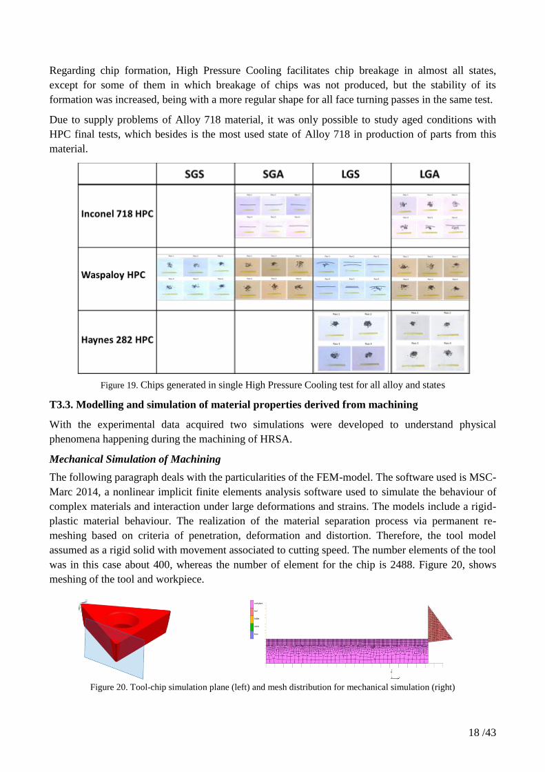
Regarding chip formation, High Pressure Cooling facilitates chip breakage in almost all states,
except for some of them in which breakage of chips was not produced, but the stability of its
formation was increased, being with a more regular shape for all face turning passes in the same test.
Due to supply problems of Alloy 718 material, it was only possible to study aged conditions with
HPC final tests, which besides is the most used state of Alloy 718 in production of parts from this
material.
Figure 19. Chips generated in single High Pressure Cooling test for all alloy and states
T3.3. Modelling and simulation of material properties derived from machining
With the experimental data acquired two simulations were developed to understand physical
phenomena happening during the machining of HRSA.
Mechanical Simulation of Machining
The following paragraph deals with the particularities of the FEM-model. The software used is MSC-
Marc 2014, a nonlinear implicit finite elements analysis software used to simulate the behaviour of
complex materials and interaction under large deformations and strains. The models include a rigid-
plastic material behaviour. The realization of the material separation process via permanent re-
meshing based on criteria of penetration, deformation and distortion. Therefore, the tool model
assumed as a rigid solid with movement associated to cutting speed. The number elements of the tool
was in this case about 400, whereas the number of element for the chip is 2488. Figure 20, shows
meshing of the tool and workpiece.
Figure 20. Tool-chip simulation plane (left) and mesh distribution for mechanical simulation (right)
Page 19
19 /43
Figure 21 shows the simulated chip formation in both states of the Haynes 282, solution treated LGS
and aged LGA. In two cases the formation of continuous chips was observed with the absence of
serrated chip with the cutting speed used in the experimental procedure.
Figure 21. Chip formation on Haynes 282 LGA (left) and Haynes LGS (right) with conventional cooling
Model for temperature prediction in cutting zone
In particular, the algorithm was aimed to the minimisation of the error defined as the difference
between the predicted and the experimental steady-state temperature at the two thermocouples
installed on the tool in the tests defined. The main goal of this model is to understand the variations
in the temperature field of the tool with different lubrication strategies. TMG (Maya) ® code was
used to model a pure thermal simulation to obtain the results of temperature distribution. TMG
(Maya) ® is the advanced thermal module from NX for complex thermal analyses, able to model
steady state and transient processes including conduction, convection and radiation, phase change,
Joule’s effect, etc. Table 4 shows the boundary conditions set on the tool temperature model.
Table 4. Cutting tool boundary conditions to model temperatures with different lubricant strategies
20
0,8
50000
500
350000
High pressure cooling HPC (80bar)
Convection to ambient [W/m2K]
Radiation to ambient [GVBF]
Convection to cutting fluid [W/m2K]
Thermal contact tool-tool holder [W/m2K]
Convection to cutting fluid [W/m2K]
Conventional cooling (6bar)
Cutting tool boundary conditions
Figure 22 shows the nodes and elements segmentation of the tool and tool holder for the considered
model. The total number of nodes is 42305 with 201977 elements of size between 0.05-2.5 mm.
Page 20
20 /43
Figure 22. Meshing elements of tool and tool-holder geometry for thermal modelling of tool temperatures.
On Figure 23 tool temperature on the cutting area is presented on turning with 6 bar and 80 bar
coolant pressure (left) and the temperature distribution on the edge of the tool on both cases (right).
Results show that in the case of 80 bar coolant pressure, the temperature at the notch area is less with
a higher gradient than 6 bar lubricant pressure, which is associated with the orientation of the jet.
Since the chip has a side flow of material and it reaches a zone of less temperature the pull-out of
tool material at the notch zone in the case of 80 bars is more dramatic. Other configurations of the
high pressure jet may avoid this phenomenon and ensure a better performance of the tool in terms of
notch apparition in the DOC line.
Figure 23. Tool temperature distribution on face turning of Alloy 718 SGA with conventional coolant at 6 bar (top of the
figure and HPC at 80 bar (bottom of the figure)
Global Model
Experimental tests were carried out in order to obtain the information needed for the simulation,
listed in T2.2, and thus, for being able to predict distortions during machining.
Page 21
21 /43
Regarding the machining sequence, CAD files from the following sequences have been obtained,
which consisted of 4 clamping stages with a total of 26 operations
Figure 24. Machining sequence and clamping system configuration
In addition, hole drilling tests were performed in all 6 faces of the ingot.
Figure 25. Hole drilling tests performed on the ingot.
The part was machined in Aluminium 7075, and measured in a Zeiss MC 850 CMM system.
Figure 26. left: Machined part; right: Part measurement in the CMM system
For simulation of the machining sequences, Virfac® software was used, from which displacements
in X and Z directions were obtained for each of the machining sequences.
The aim of this part of the simulation process was to take a step forward from the local model at the
chip scale, and go further away to simulate the distortion of the airfoil shaped simplified aero engine
component geometry during machining. For that purpose a typical aeronautic part has been designed
with Siemens NXTM 8.5 CAD software, then manufactured after a complete machining sequence
strategy of toolpath generation with the help of the CAM environment of NX software in four
Page 22
22 /43
different clamping stages, and finally measured in the CMM over all its surfaces with a total number
of 750 measuring points to have a point cloud to compare with the distortion simulations.
Figure 27.Workflow of the test piece to obtain distortion simulations
The level set method
One of the major difficulties during machining simulations is to control the undesired distortions.
These can come from various sources such as the cutting forces, imposition of the clamping system
or/and the relaxation of residual stresses. Their relative contribution depends on the workpiece shape
and material. Typically, for massive workpieces, relaxation of residual stresses is often the most
critical point. A typical example is a lamination process followed by a machining one. Lamination
introduces very high residual stresses within the workpiece which are relaxed during machining so
that unwanted distortions can appear. These kind of distortions will be predicted by Morfeo. For this,
we can focus on the workpiece-scale, neglect effects occurring at the tool tip scale and use a linear
elastic material (even if the method can handle any material law).
The main challenge of multi-pass machining modelling is to guarantee that the workpiece mesh
matches the cutting path in order to represent correctly the newly created free surfaces. This requires
numerous re-meshing steps as cutting paths are defined in the machine configuration while the
workpiece is being distorted after a first machining path.
Two types of calculation are interfaced with Virfac®: Machining direct and Machining Level Set.
Both calculations are using the theory of initial stress released: the final state of the part
(displacement and stress field) is found from an initial stress map of the initial part applied to the
final geometry. In a machining direct calculation, the input is the geometry that is obtained after
machining, to which an initial stress is applied. The calculation is done while the part is fixed
between the clamping system, and a relaxation task is then performed.
A more flexible alternative consists of making use of the level-set method. The major advantage of
such an approach is that the mesh does not have to match the boundaries anymore. The level-set is a
signed distance field with respect to the cutting paths defined at each workpiece node; at a given
node the level-set sign determines whether it lies within or outside the remaining part of the
workpiece after machining. New free surfaces corresponding to the cutting paths which go through
the workpiece mesh are applied correctly by adapting the integration procedure of the finite element
problem.
The material used follows a linear isotropic law. Its properties are the following:
Density: 2810 kg/m³
Modulus of Elasticity: 71.7 GPa
Poisson’s ratio: 0.33
Page 23
23 /43
For a better understanding, the following figure summarises the full process. The calculation code,
Morfeo, allows to process in different ways. This one was chosen because it is interfaced with
Virfac®.
Figure 28. Method to follow to find out the global displacement of the part with the level set method
Workpiece CAD geometry was divided in several cross sections, in which several points were
measured in each one. This approach was used in both sides of workpiece. Once two points clouds
were stored, they were superposed to the original CAD geometry.
Figure 29. One of the sections were points were measured, side 1.
Page 24
24 /43
From the clouds of points obtained, a change of reference frame has been done as to fit the reference
frame used in Virfac®. It can be assumed that the angle of rotation is 90° even if it might be slightly
different depending on the way the local axis were defined.
From these values, a python script has been written so to be able to compare the distortion obtained
in the simulation to the distortion obtained in the manufacturing plant. In this script, the coordinates
of its projection on the part were calculated for each point. Then the distance between the point and
its projection was compared with the value of the displacement of the projected point.
From the first cloud of points, the maximum value of displacement is 0.145 mm, the minimum value
is 8.33E-4 mm and the average value is 0.060 mm.
From the simulation, from the points corresponding to the projection of the first could of points, the
maximum value of displacement is 9.58E-3 mm, the minimum value of displacement is 9.72E-4 mm
and the average value is 6.71E-3 mm.
There is a scale factor of ten between the two results.
The values measured with the CMM are different from the one obtained with the simulation. This
can be justified by the fact that the initial stress may not be accurate, or may not have been accurately
used to create the complete stress field.
T3.4 Improvement of produceability by cryogenic machining
Added to conventional cooling tests, studies of cryogenic applications were carried out taking into
account how and where to apply the cooling media, in this case CO2. Several nozzle layouts were
tested, aiming the cooling jet at the tool tip from the frontal side, and from the lateral side, with
several different offset distances at each one. Problems encountered during the tests that made it
impossible to get a proper complete test, having chip nest problems in all passes, continuously
distorting test results and thus invalidating this approach. Figure 28 shows some of described
problems using cryogenic machining.
Figure 30. Set-up used during cryogenic and problems encountered.
Page 25
25 /43
With the intention of overcoming the problems encountered with traditional cryogenic machining, an
additional new approach of cooling was intended. It consists of a prototype delivery system with
three channels: the inner one will deliver soy oil, the middle one pressurized air and the external one
CO2, in order to avoid oil freezing. Despite the continuous insistence to the supplier of the pressure
material, it was not possible to acquire in time for its implementation, and it has not been possible to
create an alternative for security reasons. Therefore, it was not possible to evaluate this cooling
method.
WP4. Surface properties and high energy material removing methods
This work package was devoted to develop specific surface treatment methods to guarantee that
surfaces generated using high energy removal processes meet the quality requirements.
Different alternative production technologies for the manufacturing of Alloy 718 was evaluated and
analysed.
T4.1 Literature update on surface defects induced by high energy processes
A short review of high energy non-conventional processes (AWJ, LB and WEDM) for cutting
HRSAs was done, focused on the analysis of the defects produced with these technologies.
Laser Beam (LB) cutting
LB cutting is a process in which the material is heated to its melting or vaporization temperature.
Heating is achieved by concentrating the energy in a very small spot. This allows the cutting of
almost all types of materials with thickness of up to 20 mm without the need for very high levels of
energy. There are different laser generators depending on the type of the laser-active material they
use. Each type of laser creates a laser beam at a given wavelength.
Once the beam has been generated, a lens system focuses the beam on a point with diameters of
around 0.2 mm. The focusing of the beam allows for high energy densities to be reached, a typical
value is about 1.4E10
W/m2. The high power density concentrated on the spot vaporizes almost all
types of material. On the other hand, an assisting gas flow is injected coaxially to the laser beam
during cutting. Material cutting is achieved by the translation of the spot along the desired cutting
path. The most common method is the use of two axes machines.
The defects produced by LB cutting are described in Figure 31.
Figure 31. Defects produced by LB cutting
Abrasive Water Jet (AWJ) machining
AWJ machining is an emerging technology in evident growth since its first industrial application in
1983. AWJ consists of water pressurized at high hydrostatic pressure (up to 6,000 bar) which is
converted into kinetic energy and mixed with abrasive particles, forming a three phase jet (air, water
Page 26
26 /43
and abrasive) with very high velocity (300-1,000 m/s), able to erode the desired material. The low
cost of the process along with the productivity, the flexibility and its ability to machine any kind of
material without heat damage, convert the AWJ technology into an opportunity to machine difficult-
to-cut materials.
The defects produced by AWJ cutting are described in Figure 32.
Figure 32. Defects produced by AWJ cutting
Wire Electro Discharge Machining (WEDM)
In WEDM, the material removal occurs from any electrically conductive material by the initiation of
rapid and repetitive spark discharges between the gaps of work piece and tool electrode connected in
an electrical circuit. A liquid dielectric medium is continuously passed in the gap provided between
the wire and work piece. A small diameter wire ranges from 0.05 to 0.3 mm is applied as tool
electrode. The wire is continuously supplied from the supply spool through the work piece, which is
clamped on the table by the wire traction rollers. A gap of 0.025–0.05 mm is maintained constantly
between the wire and work piece. A collection tank, which is located at the bottom, is utilized to
collect the used wire.
The defects produced by WEDM are described in Figure 33.
Figure 33. Defects produced by WEDM
Ultrasonic vibration assisted milling (UVAM)
Assisted ultrasonic machining has been proven to be an efficient technique for improving the
perceived machinability of several aerospace materials such as aluminium, composites and nickel
based alloys like Alloy 718. Chip breaking, burr generation, surface roughness, tool life or torque
Page 27
27 /43
and cutting forces are some parameters studied with vibration applied in otherwise conventional
cutting processes.
The fundamentals of ultrasonic machining lies in controlled toolholder vibrations at a frequency
above the audible range up to 60 kHz approximately, which causes an extremely rapid movement on
the cutting tool of specific amplitude and in a specific direction.
T4.2 Development of surface treatment methods
In this task test-program defined in Task 2.2 for the evaluation of high energy non-conventional
technologies were carried out in Alloy 718.
Machines used in the experimental part are shown in Figure 34.
(a) (b)
(c) (d)
Figure 34. a) ROFINTM DC 025 (CO2 Laser); b) Byjet 2030L® (AWJ cutting); c) Robofil 440cc (WEDM); d) DMU
125 P DMG-Sauer 5-axis CNC milling machine.
The analysis and results obtained for each technology are described below.
LB cutting
A study the effect of the parameters on the characteristics (roughness, burr height, top kerf width and
HAZ) of the cuts obtained by LB cutting was done in Alloy 718 of thicknesses of 1.6 and 3.2 mm.
The results showed that the top kerf widths varied from 0.2mm to 0.6mm and that it is mainly
affected by the focus position. The lower the focus position, the higher the width.
Regarding the Heat Affected Zone (HAZ), obtained values varied from 0.4mm to 4.3mm. It was
found that the HAZ increases logarithmically with the energy per unit length. Thus, the HAZ
increases with the power and decreases with the traverse feed rate. In addition, there exists an
interaction between the power and the traverse feed rate. Thus, the lowest HAZ value was obtained
for 2000W of power and a traverse feed rates higher than 2000mm/min. The size of the recast layer
is between 22 and 55µm.
Page 28
28 /43
Figure 35. CO2 laser: HAZ is observed.
The obtained values for the burr height varied from 0.065mm to 1.9mm. No correlation between
process parameters and the burr height was found. For the thickness of 1.6mm, the lowest value of
the burr was 0.065mm, which was obtained for 2000W, 4000 mm/min and 1.6mm of focus position.
For the thickness of 3.2mm, the lowest value of the burr is 0.410mm, which is obtained for 500W,
100 mm/min and -3.2mm of focus position.
Finally, the obtained values for the roughness varied from 0.5µm to 3.5µm. No correlation between
process parameters and the roughness was found. For the thickness of 1.6mm, the obtained lowest
value for the roughness was 0.64µm, which was obtained for 2000W, 4000 mm/min and 1.6mm of
focus position. For the thickness of 3.2mm, the obtained lowest value of the roughness was 0.71mm,
which was obtained for 2000W, 3000 mm/min and 1.6mm of focus position.
In addition to the study of the effect of process parameters, as shown in Figure 36, higher thicknesses
of Alloy 718 were cut in a TruLaser 3030 machine.
3.2mm of thickness
6mm of thickness
8mm of thickness
10mm of thickness
Figure 36. LB cuts in different thicknesses of Alloy 718
AWJ cutting and machining
A database for cutting stainless steel and Alloy 718 of different thicknesses (from 5mm to 125mm)
was by AWJ at different cutting qualities was developed. For example, Alloy 718 of 100 mm
thickness can be cut at 16 mm/min obtaining striations and grooves in the cut surface. If the traverse
feed rate is reduced to 3 mm/min good quality can be obtained (Ra<5µm).
Page 29
29 /43
Figure 37. Abrasive embedment in AWJ cutting
In addition to the cutting process, milling can be also performed by AWJ technology, which then is
based on controlling the eroded depth. From previous experience of Tecnalia, a set of parameters
were defined for AWJ milling Alloy 718 which resulted in a material removal rate (MRR) of 680
mm3/min and on a roughness of machined surface of Ra of 8 µm. All surfaces showed embedded
abrasive particles. On the other hand, a hardness gradient is evident starting from a distance of
around 300 μm from the surface, and increasing with proximity to the surface up to 50% with respect
to the untreated bulk Alloy 718.
Since the AWJ cutting and milling process can result in a rough and wavy surface, two different
post-processing methods were tested in order to improve the surface characteristics: 1) Pure Waterjet
(PWJ) texturing; and 2) Low Plasticity Burnishing (LPB).
(a) (b) (c)
Figure 38. Alloy 718: (a) Cut by AWJ and post processed by LPB ; (b) Cut by AWJ and post-processed by PWJ and
LPB; (c) Milled by AWJ and post processed by PWJ.
The results showed that the post-processed surfaces showed lower roughness than the surfaces milled
or cut by AWJ, especially the surfaces treated with LPB, which gives a mirror-like surface. In
addition to this, the hardness gradient produced by AWJ is reduced when applying the PWJ post-
treatment, while maintained when applying the LPB treatment. Finally, the PWJ post-treatment
removed all the abrasive particles embedded in the surfaces cut or milled by AWJ.
WEDM
Cuts in Alloy 718 of 50 mm in thick were performed (Figure 39a) for characterising the process in
terms of productivity, roughness and cut width. The results showed that the most significant factors
for the feed rate and thus, for MRR are the pulse ON and OFF time and the Servo Reference Mean
Voltage. The maximum feed rate obtained was 1.68mm/min. The width of cuts varied from 0.414 to
Page 30
30 /43
0.444 mm. The surface average roughness varied from 2.77 to 4.28 µm. No white layer was
observed in the surface, due to the low aggressive conditions used in the tests (Figure 39b).
(a) (b) (c)
Figure 39. (a) cuts made by WEDM; (b) microstructure of the cut-edge; (c) Scattered electron Image (SEI) of Alloy 718
surface cut by WEDM.
Ultrasonic vibration assisted milling (UVAM)
The UVAM technology was compared to the conventional milling by machining seven specimens of
Alloy 718 in small grain aged state by each technology. The results showed that UVAM machined
workpieces did not appear to exhibit significant advantage on roughness generation on the surface.
The mean values of the forces are of similar magnitude in machining with conventional milling and
in UVAM milling in the axial direction. Changes on the surface hardness of the machined surface
were observed, with a harder surface on the UVAM machined specimens (see Figure 40).
Figure 40. Comparison between hardness results obtained in UVAM and conventional milling
Regarding the grain structure, in the case of conventional milling, little deformation of the material
during the cutting of the specimen was observed (Figure 41). On the UVAM machined specimens
deformation of a micro-layer of the sub-surface is reported. Finally, damage on the tool edge is
similar between both conventional milling and UVAM.
Page 31
31 /43
Conventional Milling UVAM
Figure 41. Cross-cut metallography images for: Conventionally (left) and UVAM machined coupons (right)
Conventional Milling UVAM
Figure 42. Scanning Electron Microscope (SEM) images of the grain structure in conventional milling (left) and
ultrasonic vibration assisted milling (right)
Fatigue Testing
The fatigue test machine used for the testing was a 100 kN servohydraulic Instron 8516 at room
temperature in constant load mode. The stress ratio R was set at 0.1. The maximum applied stress
was 1332 MPa, and the minimum 133 MPa, corresponding to a load applied in the fatigue machine
of 4,80 kN and 0,48 kN respectively. The frequency of the test was set at 3 Hz.
In order to perform fatigue tests, a specific four point bending tooling was designed for adapting the
uniaxial fatigue machine to these bending fatigue tests. The tooling was fixed to the machine by its
cylindrical shape ends. The ball joint in the upper part of the tooling avoids any kind of eccentricity
without restricting degrees of freedom.
A total of ten specimens were tested for each technology (AWJ, WEDM and conventional milling),
in US milling only 7 specimens were tested. Next figure shows equipment used and results obtained
in fatigue test.
Laser specimens have not been tested because of poor quality after cutting process, invalidating them
to prepare proper fatigue specimens within the required tolerances. The resulting samples obtained
with this technology are shown in Figure 43 where it is possible to appreciate the excessive melted
Page 32
32 /43
burr at the laser beam exit as well as surface curvature along cut specimen due to thermal distortions
that they arise during the cutting process, which makes it impossible to prepare samples inside the
correct tolerances to study in a fatigue testing.
Figure 43. Specimens cut by Laser Beam
Figure 44. Equipment and results obtained.
The results showed that for example, ultrasonic assisted milling improves fatigue life of specimens
by a 12% with the very same cutting conditions as conventional milled specimens, and that AWJ and
WEDM technology reduces the fatigue life compared to the conventional milling.
WP5. Manufacturing of Demonstrator Component
T5.1 Materials procurement and preparing
Contrary to what at the beginning of the project was intended, the topic manager proposed an
alternative approach consisting of different demonstrator parts.
One demonstrator for simulation part of the project, which required the design of a thin wall airfoil
shaped geometry, with high volume of removed material. Material procurement was necessary, an
aluminium 7075-T651 alloy widely used in aerospace industry.
It was also necessary to get some Alloy 718 plate material for the Non-conventional Machining
Methods demonstrator where AWJ milling capabilities were evaluated.
T5.2 Fabrication of the demonstrator part
Page 33
33 /43
Conventional Machining Methods
Regarding the conventional machining, HIMMOVAL project generated and developed new
knowledge in Ni-based alloys (Alloy 718, Waspaloy and Haynes 282), which took into account heat
treatment procedures, metallurgical characterisation, machinability tests and the effect of different
cooling strategies in machining and in tool behaviour.
In this context, two demonstrators were delivered:
C) Hardware demonstrator: optimisation of manufacturing sequence taking into account
initial stress map of raw material.
Different aspects must be controlled during production of high value components. In conventional
machining, a major problem is the geometrical distortion obtained after the machining of the final
workpiece. Although the project is focusing on Ni-based alloys, this demonstrator was performed in
Aluminium 7075 since it is less expensive and provides similar properties for the simulation.
For the simulation, it is necessary to know the initial stress map of the raw material, sequence of
manufacturing and clamping system used. It is important to note that force and temperature
generated during interaction were not integrated in the global model.
Figure 45. Demonstrator in Aluminium 7075.
D) Software component: machinability database for Heat Resistant Superalloys.
Alloy 718, Waspaloy and Haynes 282 were studied during the project. Aspects considered during
experimentation were:
Different states (Aged and Solution treated)
Grain Size (Small and Large grain)
Normal cooling tested (6bar) and High Pressure Cooling tested (80bar): including the
observed effects on tool wear
As results of the experimentation, a high quantity of data has been generated and recorded. A
database, with a special visualisation tool (web platform), has been developed to facilitate the
comparison between different parameters of the machining process, such as the cooling system,
different alloys and influence of properties in the tool wear life.
Page 34
34 /43
Figure 3. HIMMOVAL software.
This program helps the user to compare and analyse the data obtained by turning tests carried out
with different materials. Below we have what the user will see in the charts menu after entering his
username and password.
Figure 46. Initial Screen of HIMMOVAL web.
Variables
It allows the user to compare through graphs different variables obtained during the test. The various
possibilities can be seen below and it is possible to choose more than a variable in the Y axis at any
one time.
Page 35
35 /43
Figure 47. Different Variables to be selected
Filters
In this section, the user has to select the data that wants to see. Clicking the Trial mode, the user will
be able to select a specific test. However, if the trial type mode is selected, many tests at the same
time can be compared.
For example, user wants to compare all the LGA Haynes tests carried out. It would be enough to
choose the following options and click in add interval.
Figure 48. Alloy and type of grain selected.
Visualization options
In this section we can select the way we want to visualize the data.
Figure 49. Visualization options.
Page 36
36 /43
Figure 50. Example of visualization. Figure 51. Compare signals.
Choosing these options, selecting the chips meters and fx as variables and adding the interval
selected previously, we would obtain the previous graph.
Thanks to enabling the show tooltip button, we are able to see the value of every curve at any point
and to know the test it corresponds to.
Moreover, selecting the compare signals option, the curves overlap as we can see in Figure 51.
Finally, if the option wiki in the top left side is selected, it will be possible to see all the power points
of the test that were carried out that explain how they were done and some of the obtained results.
Non-conventional machining methods
The selected alloy used in non-conventional machining methods was Alloy 718, mainly due to the
fact it is currently the most used material for jet engine components and its mechanical properties
were verified during the conventional machining methods analysis. Alloy 718 was developed to
work in high temperature conditions while keeping its mechanical properties.
This alloy was tested using the four non-conventional methods (see above) and measured in terms of:
o surface measurements
o Scanning Electron Microscope (SEM) characterisation
o fatigue test campaign
These results were compared to conventional methods.
In addition, LPB (Low Plasticity Burnishing) as a post-processing method was applied to WEDM, LB
and UVAM and has shown to increase surface hardness of the material. Moreover, PWJ (Pure
Waterjet) as a post-processing method was applied to specimens previously machining with AWJ and
it has proven to be able to remove abrasive particles embedded in the material.
In this context, two demonstrators were delivered:
Page 37
37 /43
B) Hardware demonstrator: cutting and machining operations in Alloy 718 using non-
conventional machining methods.
Due to the availability of resources, only AWJ technology was used.
In order to evaluate the milling capabilities of AWJ technology, an extended flange feature including
a hole to “emulate” a fastener has been manufactured in Alloy 718. Figure 4, obtained in a standard
AWJ machine, shows capabilities of AWJ technology for cutting and milling in the same component.
Figure 4. AWJ demonstrator over Alloy 718.
C) Software demonstrator: Modelling of non-conventional machining methods during
machining of Nickel based material.
Figure 52. Software developed for AWJ technology.
Non-conventional machining methods, namely Laser or AWJ show some error due to the process
non-rigid cutting tool (the beam). In the case of AWJ technology, two main known errors are taper
angle and lead angle, which are directly related to the process parameters and the material to be cut.
During HIMMOVAL project, specific software has been developed based on the experimental test
done in Alloy 718 using AWJ technology.
The software allows the user to select material, thickness, range of parameters of work (Pressure and
abrasive mass flow rate), and quality of the surface, while the software will provide traverse feed rate
and taper error to compensate in a real machine. This kind of, knowledge can be used, in machine of
AWJ machining to optimize process parameters. The following pictures shows part of the software
developed.
Page 38
38 /43
Figure 53. Input to the software
Figure 54. Output to the software
T5.3 Inspection and evaluation of the demonstrator part.
Simulation demonstrator part required some analysis and verification after machining to compare
differences with respect to simulation conducted in a virtual environment.
For this purpose the, machined part was inspected in a Coordinate Measuring Machine, evaluating
about 750 points in each side of the workpiece, obtaining a point cloud which was later introduced in
the resulting machined geometry from the CAM postprocessor to get exclude machining
discrepancies. Through this way only distortion discrepancies due to initial residual stresses from the
original ingot were taken into account.
These discrepancy values were then compared to distortion simulation results from the partner
Geonx. The initial stress field from the upwind process (lamination) was measured and used in this
simulation. The simulations were completed using Virfac® Machining according to methodologies:
using (i) the level-set technique and the (ii) direct approach based on an immediate relaxation
simulation. The experimental validation was used to compare the measured residual distortions
against the simulation results. A sensitivity study was handled. The results show a high influence of
the initial stresses on the residual distortions.
Page 39
39 /43
EXPECTED FINAL RESULTS AND POTENTIAL IMPACTS
Potential impact of HIMMOVAL results
The number of aircrafts is highly increasing over the next 20 years according to the Airbus Global
Market Forecast (AGMF)1. Regarding the increase of aircrafts (3.7% per year) resulting from the
growth of air traffic per year (4.7% per year), in 2034 more than 38.000 aircrafts are estimated to be
in service. Of these, 19.000 are necessary due to growth, whereas 13.000 will be replacement of
actual airplanes, leading to 32.000 new aircrafts which need to be built.
Figure 55. Estimation of aircraft up to 20341
This leads to a significantly increasing necessity of manufacturing high-temperature resistant
materials used in the turbo-machinery. Superalloys used in aerospace, such as nickel base and
titanium alloys, are usually employed because of their unique combination of properties like high
strength at elevated temperatures, resistance to chemical degradation and wear resistance.
Ability to maintain these properties at elevated temperatures severely hinders the machinability of
these alloys, thus, they are generally referred to as difficult-to-cut alloys. Most problems encountered
during machining are due to heat generation, mainly during the deformation process and friction at
the tool–chip and tool–workpiece interfaces, and the consequent high temperatures associated with it.
Other characteristics of aerospace superalloys include their austenitic matrix which make them
harden rapidly; their ability to react with tool materials under atmospheric conditions; their tendency
to form built-up edge and to weld to cutting tools. The associated manufacturing cost is high because
of low material removal rates and rapid tool wear. The machining of these alloys is characterized by
low productivity and low process stability as a result of their physical and mechanical properties.
Major problems during the machining of these materials are very high thermal and mechanical tool
loads. This results in low applicable cutting speeds due to excessive tool wear, long machining times,
and thus high manufacturing costs.
Furthermore, there is a variety of nickel-base alloys, each with specific particularities regarding the
machinability and surface integrity behaviour. Among the nickel-based alloys, Alloy 718 is the most
widely used alloy and because of that it has been studied extensively for the analysis of surface
integrity, residual stress and machinability. The machining studies are not limited to Alloy 718, it's
1 Airbus Global Market Forecast (2015-2034)
Page 40
40 /43
necessary to investigated others nickel-based alloys: NiCr20TiAl, IN-100, In-738LC,
UDIMET720LI, Nimonic75 and 105, Allvac 718+, Waspaloy, Haynes 282, etc. However, their poor
thermal properties are a problem for produce good surface results at elevated temperatures due to
deformation and friction induced heat that produce an microstructural changes.
Thus, once established all aspects of the production process of a part, such as the a) number and
order of machining operations, b) cutting conditions, c) cooling systems, d) choice of cutting tools, e)
monitoring systems and f) inspection routines, a complete testing of machined part in a testing
laboratory is required.
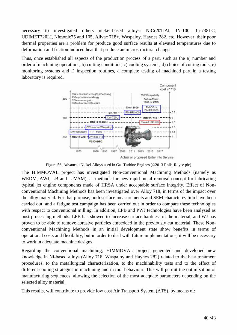
Figure 56. Advanced Nickel Alloys used in Gas Turbine Engines (©2013 Rolls-Royce plc)
The HIMMOVAL project has investigated Non-conventional Machining Methods (namely as
WEDM, AWJ, LB and UVAM), as methods for new rapid metal removal concept for fabricating
typical jet engine components made of HRSA under acceptable surface integrity. Effect of Non-
conventional Machining Methods has been investigated over Alloy 718, in terms of the impact over
the alloy material. For that purpose, both surface measurements and SEM characterization have been
carried out, and a fatigue test campaign has been carried out in order to compare these technologies
with respect to conventional milling. In addition, LPB and PWJ technologies have been analysed as
post-processing methods. LPB has showed to increase surface hardness of the material, and WJ has
proven to be able to remove abrasive particles embedded in the previously cut material. These Non-
conventional Machining Methods in an initial development state show benefits in terms of
operational costs and flexibility, but in order to deal with future implementations, it will be necessary
to work in adequate machine designs.
Regarding the conventional machining, HIMMOVAL project generated and developed new
knowledge in Ni-based alloys (Alloy 718, Waspaloy and Haynes 282) related to the heat treatment
procedures, to the metallurgical characterization, to the machinability tests and to the effect of
different cooling strategies in machining and in tool behaviour. This will permit the optimisation of
manufacturing sequences, allowing the selection of the most adequate parameters depending on the
selected alloy material.
This results, will contribute to provide low cost Air Transport System (ATS), by means of:
Page 41
41 /43
Exploitation of the capabilities of low cost methods (Abrasive Water Jet, LPB). The
equipment required for the proposed technologies is more affordable than their conventional
alternatives (ex.: 5-axis water jet machine about 30% cheaper than 5-axis milling machine2).
Costs derived from cutting tools for water jet are also lower than conventional cutting tools
(ex.: abrasive plus nozzle about 2.5€/m against 12€/m approximately by insert3). Regarding
LPB tools compared to grinding wheels, one single burnishing tool can adapt to different
surface geometries, different tool designs are available in the market and tools do not require
redressing.
Increased productivity through replacement of conventional machining sequences by AWJ
cutting of bulk material as well as through the use of optimized machinability data for
conventional machining that will lead to higher values of the MRR.
Exploitation of project results
The generated results enabled a new chain of manufacturing, optimizing selection of removal
processes for high temperature resistant super alloys.
Conventional Machining Methods
1. Effect on the tool wear has been related with:
Size of grain and state of different alloys,
Influence of cooling system,
2. Benefits of using simulation approach for machining of HRSA, in two aspects.
Global model to predict final distorsion taking into account residual stress field in the raw
material,
Local model for predict temperature and force in the interaction material and tool
Non-conventional Machining Methods
1. A new chain of manufacturing process, based on AWJ, Laser and WEDM in collaboration with
conventional manufacturing methods have been demonstrated,
2. New post processing technologies (LPB and PWJ) have improved surface generated with Non-
conventional Machining Methods.
3. Benefits of UVAM for machining of nickel base materials and industrialization of the process
have been demonstrated.
2 Source: OEMs
3 Tentative estimations based on the consortium’s experience
Page 42
42 /43
The different partners will exploit the results as follows:
1) TECNALIA R&I and UPV/EHU
The exploitation of project results will be accomplished in the following topics:
Machinability of HRSA (Alloy 718, Waspaloy, and Haynes 282), in terms of:
o Influence of heat treatments on Metallurgic properties;
o Wear effect of the cutting tool, based on effects of the cooling system used (High
Pressure Cooling, Cryogenic Cooling);
o Improvement obtained through ultrasonic assisted milling process as alternative
method of cutting;
o Software for analysis of experiments and optimisation of manufacturing
sequences.
Non-conventional machining methods using HRSA materials, in terms of:
o Applicability of technologies
o Effect of the technology in the material
o Post-processing sequence to meet the requirements from the aeronautic sector
Five scientific papers are being drafted and will be submitted to scientific journals to spread
knowledge generated over HRSA, namely:
Date estimated for publication
Title
2016 Influence of Cooling system on the wear cemented carbide tools during
machining wrought Alloy 718.
2016 US during machining wrought Alloy 718
2017 Alternative Technologies of Machining Alloy 718
2017 Tool wear analysis and improvement of cutting conditions Alloy 718
Waspaloy
2017 An Investigation of cutting forces and tool wear in turning of Haynes 282
Due to the high technical requirements and the short duration of HIMMOVAL project, the
participation in specialized forums and conferences has not been possible within the project.
However, the results obtained in the project will be used for future participation in scientific
conferences, with the aim of sharing knowledge generated within the project
Internal communication between TECNALIA R&I and UPV/EHU will be organised in June
2016, involving more scientists from both organisations to reflect upon further use of the
results. Moreover, Tecnalia R&I hired a PhD candidate in March 2016 to continue working on
the optimisation of the sequence of manufacturing using HIMMOVAL’s results. In addition,
UPV/EHU (University of Basque Country) is considering including a new Master focused on
machining HRSA..
Page 43
43 /43
GEONX
By adding physics in Morfeo software, there is a high potential for selling more expertise on
addressed topics and licenses of the new modules developed within the framework of the
project.
Improvement of the software accuracy thanks to the massive experimental approach of the
HIMMOVAL project will enhance the fidelity of Morfeo against physical observations.
Results obtained in HIMMOVAL project have been very useful in developing numerous new
features in Virfac® Machining, in particular within a new module called Machining Direct.
Topic Manager
Include the results obtained in current productions of Alloy 718, Waspaloy and Haynes 282.
Transfer technical results obtained in the project to the Research centres and Universities
closed to its facilities to obtain higher participation in the research field.
Redesign component manufacturing strategies taking into account the potential of Non-
conventional Machining Methods used in HIMMOVAL.
Develop new machine concepts and standardisation for Non-conventional Machining
Methods.