4100-5120/5121/5122 TrueAlert ® Power Supply Installation Instructions 2001-2011 SimplexGrinnell LP. All rights reserved. Specifications and other information shown were current as of publication and are subject to change without notice. Simplex and the Simplex logo are trademarks of Tyco International Ltd. and its affiliates and are used under license.. 579-336 Rev. K This publication provides an overview of the features, specifications, and capabilities of the TrueAlert ® power supplies (TPS). These supplies provide auxiliary power, a battery charger, and three Signaling Line Circuits (SLC). Each of which provides control and power to the full range of TrueAlert appliances. The TrueAlert power supplies are identical to each other with the following exceptions: 4100-5120 Domestic (US) version, requires a 120 VAC power source. 4100-5121 Canadian version, requires 120 VAC power source and provides battery cutout option. After installing a 4100-5121, refer to “Enabling Low Battery Cutout Option” in the ES Panel Programmer’s Manual (574-849) for information on enabling this option. 4100-5122 International version, uses a 220/240 VAC power source. If you are wiring Class A circuits, you need to install a 4100-5124 Class A Adapter Card onto the TrueAlert Power Supply before installing the power supply. Refer to Document # 579-337 for more information. This product is compatible with the 4100U and 4100ES Fire Alarm Control Panel (FACP). IMPORTANT: Verify FACP System Programmer, Executive, and Slave Software compatibility when installing, or replacing system components. Refer to the Technical Support Information and Downloads website for compatibility information. This publication discusses the following topics: Topic See Page # Cautions and Warnings 2 Introduction to the TPS 3 Mounting 6 Configuring the TPS 7 Power Distribution Module/Battery Connections 9 Compatible TrueAlert Devices 10 General Wiring Guidelines 12 Wiring Class A Circuits 14 Wiring Class B Circuits 17 Wiring AUX Power 20 Troubleshooting 21 Introduction In this Publication
Transcript
4100-5120/5121/5122 TrueAlert® Power Supply Installation Instructions
2001-2011 SimplexGrinnell LP. All rights reserved. Specifications and other information shown were current as of publication and are subject to change without notice. Simplex and the Simplex logo are trademarks of Tyco International Ltd. and its affiliates and are used under license..
579-336 Rev. K
This publication provides an overview of the features, specifications, and capabilities of the TrueAlert® power supplies (TPS). These supplies provide auxiliary power, a battery charger, and three Signaling Line Circuits (SLC). Each of which provides control and power to the full range of TrueAlert appliances. The TrueAlert power supplies are identical to each other with the following exceptions: 4100-5120 Domestic (US) version, requires a 120 VAC power source.
4100-5121 Canadian version, requires 120 VAC power source and provides battery cutout option. After installing a 4100-5121, refer to “Enabling Low Battery Cutout Option” in the ES Panel Programmer’s Manual (574-849) for information on enabling this option.
4100-5122 International version, uses a 220/240 VAC power source. If you are wiring Class A circuits, you need to install a 4100-5124 Class A Adapter Card onto the TrueAlert Power Supply before installing the power supply. Refer to Document # 579-337 for more information. This product is compatible with the 4100U and 4100ES Fire Alarm Control Panel (FACP). IMPORTANT: Verify FACP System Programmer, Executive, and Slave Software
compatibility when installing, or replacing system components. Refer to the Technical Support Information and Downloads website for compatibility information.
This publication discusses the following topics:
Topic See Page #
Cautions and Warnings 2
Introduction to the TPS 3
Mounting 6
Configuring the TPS 7
Power Distribution Module/Battery Connections 9
Compatible TrueAlert Devices 10
General Wiring Guidelines 12
Wiring Class A Circuits 14
Wiring Class B Circuits 17
Wiring AUX Power 20
Troubleshooting 21
Introduction
In this Publication
2
READ AND SAVE THESE INSTRUCTIONS- Follow the instructions in this installation manual. These instructions must be followed to avoid damage to this product and associated equipment. Product operation and reliability depend upon proper installation.
DO NOT INSTALL ANY SIMPLEX® PRODUCT THAT APPEARS DAMAGED- Upon unpacking
your Simplex product, inspect the contents of the carton for shipping damage. If damage is
apparent, immediately file a claim with the carrier and notify an authorized Simplex product
supplier.
ELECTRICAL HAZARD - Disconnect electrical field power when making any internal adjustments
or repairs. All repairs should be performed by a representative or authorized agent of your local
Simplex product supplier.
STATIC HAZARD - Static electricity can damage components. Handle as follows:
Ground yourself before opening or installing.
Prior to installation, keep components wrapped in anti-static material at all times.
EYE SAFETY HAZARD - Under certain fiber optic application conditions, the optical output of
this device may exceed eye safety limits. Do not use magnification (such as a microscope or other
focusing equipment) when viewing the output of this device.
FCC RULES AND REGULATIONS – PART 15 - This equipment has been tested and found to comply with the limits for a Class A digital device pursuant to Part 15 of the FCC Rules. These limits are designed to provide reasonable protection against harmful interference when the equipment is operated in a commercial environment. This equipment generates, uses, and can radiate radio frequency energy and, if not installed and used in accordance with the instruction manual, may cause harmful interference to radio communications. Operation of this equipment in a residential area is likely to cause harmful interference in which case the user will be required to correct the interference at his own expense.
SYSTEM REACCEPTANCE TEST AFTER SOFTWARE CHANGES - To ensure proper system operation, this product must be tested in accordance with NFPA 72 after any programming operation or change in site-specific software. Reacceptance testing is required after any change, addition or deletion of system components, or after any modification, repair or adjustment to system hardware or wiring. All components, circuits, system operations, or software functions known to be affected by a change must be 100% tested. In addition, to ensure that other operations are not inadvertently affected, at least 10% of initiating devices that are not directly affected by the change, up to a maximum of 50 devices, must also be tested and proper system operation verified.
Cautions and Warnings
3
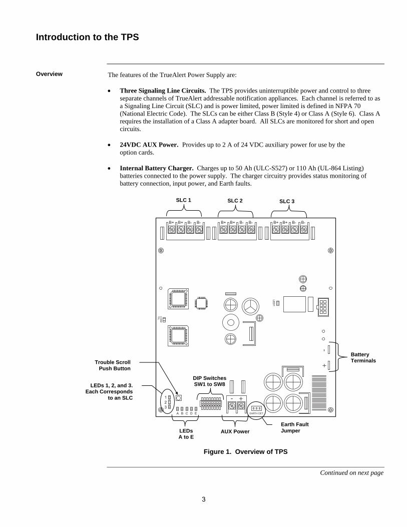
The features of the TrueAlert Power Supply are: Three Signaling Line Circuits. The TPS provides uninterruptible power and control to three
separate channels of TrueAlert addressable notification appliances. Each channel is referred to as a Signaling Line Circuit (SLC) and is power limited, power limited is defined in NFPA 70 (National Electric Code). The SLCs can be either Class B (Style 4) or Class A (Style 6). Class A requires the installation of a Class A adapter board. All SLCs are monitored for short and open circuits.
24VDC AUX Power. Provides up to 2 A of 24 VDC auxiliary power for use by the
option cards. Internal Battery Charger. Charges up to 50 Ah (ULC-S527) or 110 Ah (UL-864 Listing)
batteries connected to the power supply. The charger circuitry provides status monitoring of battery connection, input power, and Earth faults.
Figure 1. Overview of TPS
Continued on next page
Introduction to the TPS
Overview
SLC 1 SLC 2 SLC 3
Battery Terminals
LEDs A to E
DIP SwitchesSW1 to SW8LEDs 1, 2, and 3.
Each Corresponds to an SLC
Trouble Scroll Push Button
Earth Fault Jumper AUX Power
4
Full TrueAlert Operation. TrueAlert addressable notification appliances are individually addressed and receive power, supervision, and control signals over the SLC. Horns sound with selectable high or low output, using a temporal, march time (60 or 120 beats per minute), or continuous pattern. Horns are controlled separately from visible appliances installed on the same two-wire circuit. (Combination speaker/strobe TrueAlert appliances receive audible control from separate audio circuit wiring.)
Extensive Diagnostic Capabilities. LEDs on the TPS flash codes that identify the nature of trouble conditions. The TPS also monitors for short and open circuits and positive and negative Earth fault status.
Depleted Battery Cutout (Canadian Version Only). When AC Power fails, the Depleted Battery Cutout feature disconnects a battery from the panel when its voltage is approximately 18 VDC.
Visual Synchronization. A maximum of 46 MultiCandela addressable visuals may be synchronized per SLC. All SLCs are synchronized across a TPS. All TPSs are synchronized across the FACP.
The following table summarizes the AC Input, DC Output, and Battery Charger specifications of the TPS.
Table 1. AC Input, DC Output, Battery Charger Specifications
AC Input Specifications
4100-5120/5121 4 A Maximum 120 VAC @ 60 Hz
4100-5122 2 A Maximum 220/230/240 VAC @ 50 or 60 Hz
DC Output Specifications
Aux Power and Each SLC
Minimum: 19 VDC Maximum: 32 VDC Ripple: 2 VDC, peak to peak @ full load (9A)
Battery Charger Specifications
Input Voltage Range
21-33 VDC
Output Voltage 27.4 VDC ± 500 mV @ 68° F (20° C), temperature compensated at –24 mV / deg. C
High Voltage Output
29.1 V @ 3.3 A
Output Current Limit
1.4 A (For 6.2 –18 Ah battery) 3.3 A (Default for 18-50 Ah battery [Canada]; 18-110 Ah battery [United States])
Continued on next page
Introduction to the TPS, Continued
Additional Features
Input/Output/Battery Specifications
5
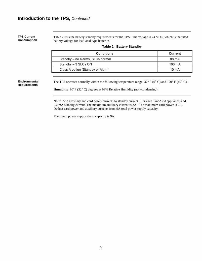
Table 2 lists the battery standby requirements for the TPS. The voltage is 24 VDC, which is the rated battery voltage for lead-acid type batteries.
Table 2. Battery Standby
Conditions Current
Standby – no alarms, SLCs normal 88 mA
Standby – 3 SLCs ON 100 mA
Class A option (Standby or Alarm) 10 mA
The TPS operates normally within the following temperature range: 32° F (0° C) and 120° F (49° C). Humidity: 90°F (32° C) degrees at 93% Relative Humidity (non-condensing). Note: Add auxiliary and card power currents to standby current. For each TrueAlert appliance, add 0.2 mA standby current. The maximum auxiliary current is 2A. The maximum card power is 2A. Deduct card power and auxiliary currents from 9A total power supply capacity. Maximum power supply alarm capacity is 9A.
Introduction to the TPS, Continued
TPS Current Consumption
Environmental Requirements
6
The TPS mounts onto the right side of an expansion box, and connects to the Power Distribution Interface (PDI).
1. Slide the two tabs on the bottom of the TPS into the rightmost two slots on the expansion bay. 2. Push the TPS assembly against the back of the expansion bay.
a. Connect to the PDI, as shown below.
b. Three PDI headers, shown below, must be pushed through the three open slots in the back of the TPS assembly.
c. Align the two screw holes at the top of the TPS assembly with the holes in the cabinet backplane.
3. Use two #6 torx screws to secure the assembly to the expansion bay.
Figure 2. TPS Mounting
Mounting
Overview
Mounting Procedure
7
The Earth Fault Enable/Disable jumper allows you to enable or disable positive and negative Earth Fault detection. Place the jumper block on Pins 1 and 2 to enable Earth fault detection. Place the jumper block on Pins 2 and 3 to disable Earth fault detection. See below. FigureTag FD9-336-01 Note: When one or more TPS unit resides in a system sharing a common “0V” with any other type
power supply (SPS/RPS/XPS), jumper only one of the TPS units to enable Earth Fault Detection. All other power supplies must be jumpered to disable Earth Fault Detection. Ensure that the Slave Exec firmware, later than Revision 1.04, is loaded on this TPS.
The TPS device address is set via DIP switch SW1, which is a bank of eight switches. From left to right (see figure below), these switches are designated as SW1-1 through SW1-8. The function of these switches is as follows: SW1-1. This switch sets the baud rate for the internal FACP communications line running between the card and the FACP CPU. Set this switch to ON. SW1-2 through SW1-8. These switches set the card’s address within the FACP. Note: You must set these switches to the value assigned to the card by the Programmer.
FigureTag FD9-336-02
1 8 7 6 5 4 3 2
Figure 3. DIP Switch SW1
Continued on next page
Configuring the TPS
Setting Earth Fault Enable/Disable Jumper
Setting Address Switch
ON
OFF
DIP Switches SW1-2 through SW1-8 set the Card Address.
1 ON ON ON ON ON ON OFF 61 ON OFF OFF OFF OFF ON OFF
2 ON ON ON ON ON OFF ON 62 ON OFF OFF OFF OFF OFF ON
3 ON ON ON ON ON OFF OFF 63 ON OFF OFF OFF OFF OFF OFF
4 ON ON ON ON OFF ON ON 64 OFF ON ON ON ON ON ON
5 ON ON ON ON OFF ON OFF 65 OFF ON ON ON ON ON OFF
6 ON ON ON ON OFF OFF ON 66 OFF ON ON ON ON OFF ON
7 ON ON ON ON OFF OFF OFF 67 OFF ON ON ON ON OFF OFF
8 ON ON ON OFF ON ON ON 68 OFF ON ON ON OFF ON ON
9 ON ON ON OFF ON ON OFF 69 OFF ON ON ON OFF ON OFF
10 ON ON ON OFF ON OFF ON 70 OFF ON ON ON OFF OFF ON
11 ON ON ON OFF ON OFF OFF 71 OFF ON ON ON OFF OFF OFF
12 ON ON ON OFF OFF ON ON 72 OFF ON ON OFF ON ON ON
13 ON ON ON OFF OFF ON OFF 73 OFF ON ON OFF ON ON OFF
14 ON ON ON OFF OFF OFF ON 74 OFF ON ON OFF ON OFF ON
15 ON ON ON OFF OFF OFF OFF 75 OFF ON ON OFF ON OFF OFF
16 ON ON OFF ON ON ON ON 76 OFF ON ON OFF OFF ON ON
17 ON ON OFF ON ON ON OFF 77 OFF ON ON OFF OFF ON OFF
18 ON ON OFF ON ON OFF ON 78 OFF ON ON OFF OFF OFF ON
19 ON ON OFF ON ON OFF OFF 79 OFF ON ON OFF OFF OFF OFF
20 ON ON OFF ON OFF ON ON 80 OFF ON OFF ON ON ON ON
21 ON ON OFF ON OFF ON OFF 81 OFF ON OFF ON ON ON OFF
22 ON ON OFF ON OFF OFF ON 82 OFF ON OFF ON ON OFF ON
23 ON ON OFF ON OFF OFF OFF 83 OFF ON OFF ON ON OFF OFF
24 ON ON OFF OFF ON ON ON 84 OFF ON OFF ON OFF ON ON
25 ON ON OFF OFF ON ON OFF 85 OFF ON OFF ON OFF ON OFF
26 ON ON OFF OFF ON OFF ON 86 OFF ON OFF ON OFF OFF ON
27 ON ON OFF OFF ON OFF OFF 87 OFF ON OFF ON OFF OFF OFF
28 ON ON OFF OFF OFF ON ON 88 OFF ON OFF OFF ON ON ON
29 ON ON OFF OFF OFF ON OFF 89 OFF ON OFF OFF ON ON OFF
30 ON ON OFF OFF OFF OFF ON 90 OFF ON OFF OFF ON OFF ON
31 ON ON OFF OFF OFF OFF OFF 91 OFF ON OFF OFF ON OFF OFF
32 ON OFF ON ON ON ON ON 92 OFF ON OFF OFF OFF ON ON
33 ON OFF ON ON ON ON OFF 93 OFF ON OFF OFF OFF ON OFF
34 ON OFF ON ON ON OFF ON 94 OFF ON OFF OFF OFF OFF ON
35 ON OFF ON ON ON OFF OFF 95 OFF ON OFF OFF OFF OFF OFF
36 ON OFF ON ON OFF ON ON 96 OFF OFF ON ON ON ON ON
37 ON OFF ON ON OFF ON OFF 97 OFF OFF ON ON ON ON OFF
38 ON OFF ON ON OFF OFF ON 98 OFF OFF ON ON ON OFF ON
39 ON OFF ON ON OFF OFF OFF 99 OFF OFF ON ON ON OFF OFF
40 ON OFF ON OFF ON ON ON 100 OFF OFF ON ON OFF ON ON
41 ON OFF ON OFF ON ON OFF 101 OFF OFF ON ON OFF ON OFF
42 ON OFF ON OFF ON OFF ON 102 OFF OFF ON ON OFF OFF ON
43 ON OFF ON OFF ON OFF OFF 103 OFF OFF ON ON OFF OFF OFF
44 ON OFF ON OFF OFF ON ON 104 OFF OFF ON OFF ON ON ON
45 ON OFF ON OFF OFF ON OFF 105 OFF OFF ON OFF ON ON OFF
46 ON OFF ON OFF OFF OFF ON 106 OFF OFF ON OFF ON OFF ON
47 ON OFF ON OFF OFF OFF OFF 107 OFF OFF ON OFF ON OFF OFF
48 ON OFF OFF ON ON ON ON 108 OFF OFF ON OFF OFF ON ON
49 ON OFF OFF ON ON ON OFF 109 OFF OFF ON OFF OFF ON OFF
50 ON OFF OFF ON ON OFF ON 110 OFF OFF ON OFF OFF OFF ON
51 ON OFF OFF ON ON OFF OFF 111 OFF OFF ON OFF OFF OFF OFF
52 ON OFF OFF ON OFF ON ON 112 OFF OFF OFF ON ON ON ON
53 ON OFF OFF ON OFF ON OFF 113 OFF OFF OFF ON ON ON OFF
54 ON OFF OFF ON OFF OFF ON 114 OFF OFF OFF ON ON OFF ON
55 ON OFF OFF ON OFF OFF OFF 115 OFF OFF OFF ON ON OFF OFF
56 ON OFF OFF OFF ON ON ON 116 OFF OFF OFF ON OFF ON ON
57 ON OFF OFF OFF ON ON OFF 117 OFF OFF OFF ON OFF ON OFF
58 ON OFF OFF OFF ON OFF ON 118 OFF OFF OFF ON OFF OFF ON
59 ON OFF OFF OFF ON OFF OFF 119 OFF OFF OFF ON OFF OFF OFF
60 ON OFF OFF OFF OFF ON ON
Table 3. Card Addresses
9
The TPS gets its power from the Power Distribution Module (PDM). The PDM takes power directly from a dedicated AC line and the two backup batteries, and distributes power to each bay in the cabinet.
The Power Distribution Module (PDM) connects to every power supply in each back box. Connect the 734-012 Harness from the top connector on the PDM to the TPS. 1. Wire 120 VAC to the PDM, keeping AC wires at least one inch away from all other wires.
AC power must be kept to the right side of the cabinet, in the non-power-limited area.
2. Connect batteries to P5 on the PDM using Harness 734-015.
3. Connect the PDM to the TPS using Harness 734-012.
Connect the separate Red and Black wires (with Yellow female terminations) to Plugs P5 (Black) and P4 (Red) on the TPS.
Connect the White and Black wires, which terminate together in a White snap-on connector, to the bulkhead connector at the bottom of the TPS assembly, as shown below.
Figure 4. PDM/Battery Connections
Power Distribution Module/Battery Connections
Overview
Power Distribution Module Connections
220/230/240V PART NUMBERS APPEAR IN ITALICS.
10
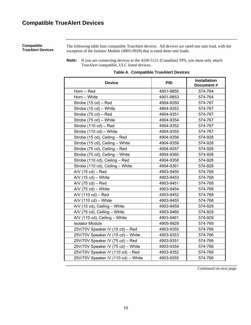
The following table lists compatible TrueAlert devices. All devices are rated one unit load, with the exception of the Isolator Module (4905-9929) that is rated three unit loads. Note: If you are connecting devices to the 4100-5121 (Canadian) TPS, you must only attach
TrueAlert compatible, ULC listed devices.
Table 4. Compatible TrueAlert Devices
Device PID Installation Document #
Horn -- Red 4901-9850 574-764
Horn – White 4901-9853 574-764
Strobe (15 cd) – Red 4904-9350 574-767
Strobe (15 cd) – White 4904-9353 574-767
Strobe (75 cd) – Red 4904-9351 574-767
Strobe (75 cd) – White 4904-9354 574-767
Strobe (110 cd) – Red 4904-9352 574-767
Strobe (110 cd) – White 4904-9355 574-767
Strobe (15 cd), Ceiling – Red 4904-9356 574-928
Strobe (15 cd), Ceiling – White 4904-9359 574-928
Strobe (75 cd), Ceiling – Red 4904-9357 574-928
Strobe (75 cd), Ceiling – White 4904-9360 574-928
Strobe (110 cd), Ceiling – Red 4904-9358 574-928
Strobe (110 cd), Ceiling – White 4904-9361 574-928
A/V (15 cd) – Red 4903-9450 574-768
A/V (15 cd) – White 4903-9453 574-768
A/V (75 cd) – Red 4903-9451 574-768
A/V (75 cd) – White 4903-9454 574-768
A/V (110 cd) – Red 4903-9452 574-768
A/V (110 cd) – White 4903-9455 574-768
A/V (15 cd), Ceiling – White 4903-9459 574-929
A/V (75 cd), Ceiling – White 4903-9460 574-929
A/V (110 cd), Ceiling – White 4903-9461 574-929
Isolator Module 4905-9929 574-769
25V/70V Speaker /V (15 cd) – Red 4903-9350 574-766
25V/70V Speaker /V (15 cd) – White 4903-9353 574-766
25V/70V Speaker /V (75 cd) – Red 4903-9351 574-766
25V/70V Speaker /V (75 cd) – White 4903-9354 574-766
25V/70V Speaker /V (110 cd) – Red 4903-9352 574-766
25V/70V Speaker /V (110 cd) -- White 4903-9355 574-766
Continued on next page
Compatible TrueAlert Devices
Compatible TrueAlert Devices
11
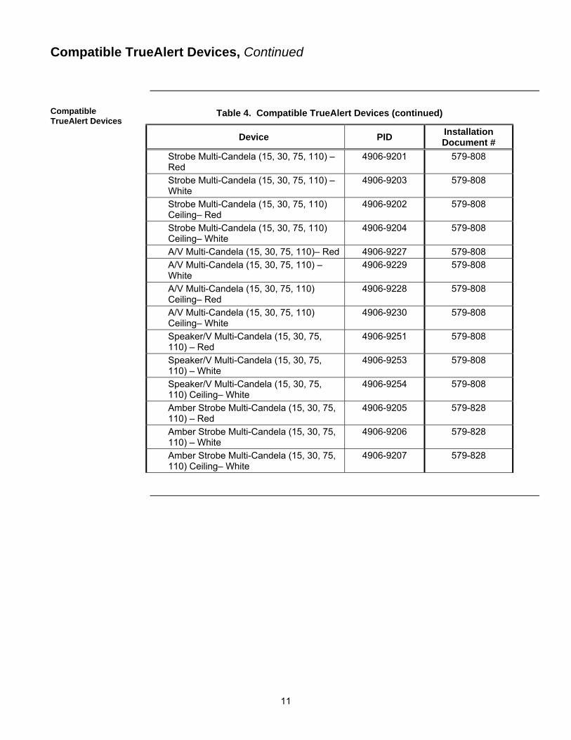
Table 4. Compatible TrueAlert Devices (continued)
Device PID Installation Document #
Strobe Multi-Candela (15, 30, 75, 110) – Red
4906-9201 579-808
Strobe Multi-Candela (15, 30, 75, 110) – White
4906-9203 579-808
Strobe Multi-Candela (15, 30, 75, 110) Ceiling– Red
4906-9202 579-808
Strobe Multi-Candela (15, 30, 75, 110) Ceiling– White
4906-9204 579-808
A/V Multi-Candela (15, 30, 75, 110)– Red 4906-9227 579-808
A/V Multi-Candela (15, 30, 75, 110) – White
4906-9229 579-808
A/V Multi-Candela (15, 30, 75, 110) Ceiling– Red
4906-9228 579-808
A/V Multi-Candela (15, 30, 75, 110) Ceiling– White
4906-9230 579-808
Speaker/V Multi-Candela (15, 30, 75, 110) – Red
4906-9251 579-808
Speaker/V Multi-Candela (15, 30, 75, 110) – White
4906-9253 579-808
Speaker/V Multi-Candela (15, 30, 75, 110) Ceiling– White
4906-9254 579-808
Amber Strobe Multi-Candela (15, 30, 75, 110) – Red
4906-9205 579-828
Amber Strobe Multi-Candela (15, 30, 75, 110) – White
4906-9206 579-828
Amber Strobe Multi-Candela (15, 30, 75, 110) Ceiling– White
4906-9207 579-828
Compatible TrueAlert Devices, Continued
Compatible TrueAlert Devices
12
Use only copper conductors for all wiring applications. All equipment must be installed in accordance with the manufacturer’s recommendations and the specifications and standards of the authority having jurisdiction (AHJ). The installation of all wiring, cable, and equipment must be in accordance with NFPA 70 and the National Electrical Code (NEC), specifically Article 760 (Fire Alarm Systems), Article 800 (Communications Circuits).
If applicable, the installation must be in accordance with the Canadian Building Code, and any provincial and/or local requirements.
Each TrueAlert channel is limited to 0.60uF maximum capacitance. This includes conductor to conductor and conductor to shield capacitance (if shield wire is used).
TPS wiring must use ferrite beads in order to comply with the RF Immunity test specified in UL864
If shielded wire is used, the following must be observed.
Metallic continuity of the shield must be maintained and insulated throughout the entire length of the cable.
The entire length of the cable must have a resistance greater than 1 Mega ohm to Earth.
Underground wiring must be free of all water.
Wiring other than that connected to elevator cabs must not be run in elevator shafts (reference NFPA 70, Article 620).
Wiring in ducts, plenums, and other air handling spaces must be installed in accordance with NFPA 70, Article 300.
Splicing is permitted in accordance with NFPA 70. All junctions must be insulated as soundly as the original jacket. Continuity of shields (where used) must be maintained.
A system ground must be provided for Earth detection and lightning protection devices. This connection shall be made to an approved, dedicated Earth connection, per NFPA 70, Article 250.
Only system wiring can be run in the same conduit.
Field wiring circuits shall not leave the building of origin unless all of the following conditions are met.
Circuits are protected from lightning by utilization of either the Model 2081-9044 or the Model 2081-9028 listed isolated loop circuit protectors.
One isolated loop circuit protector is inserted into the circuit where the wiring leaves the building. A second isolated loop circuit protector is inserted into the circuit where the wiring enters the next building.
Underground wiring circuits are run in a parallel wiring trough separate from any commercial power distribution wiring.
Overhead circuit wiring is run in parallel with relation to the commercial power distribution wiring. Overhead circuit wiring is separated from the commercial power distribution wiring by a minimum distance equal to the maximum span between two adjacent poles of either the system’s circuit or the commercial power distribution circuit, or 100 feet (30 m), whichever is greater. Outside plant wiring is limited to one contiguous property and the total wire length may not exceed 3,270 feet (997 m).
Continued on next page
General Wiring Guidelines
General Wiring Guidelines
13
Conduit Entrance for Non-Power Limited Wiring
Adhere to these guidelines when wiring power limited and non-power limited wiring within the FACP.
Non-power limited field wiring (AC power, batteries) must be installed and routed in the shaded areas shown in the figure below.
Power-limited field wiring must be installed and routed in the non-shaded areas shown in the figure below.
Excess slack should be kept to a minimum inside the back box enclosure. The wiring should be neatly dressed and bundled together using the wire ties provided with the equipment. Anchor power-limited wiring to tie points, as shown in the figure below.
Tie the wiring located between bays to the internal wiring troughs, if applicable.
When powering remote units or switching power through relay contacts, power for these circuits must be provided by a power-limited power supply that is UL listed for fire-protective signaling use. A UL listed EOL relay must be used to supervise the auxiliary power circuit.
IMPORTANT: If the TPS is powered up with zero devices connected, the TPS
indicates channel failure for those channels that are programmed to support devices. The TPS does not sense devices as they are connected when the TPS has been powered up with zero devices connected. After at least one valid device is connected, the unit must be reset by toggling the DIP Switch SW1-1 OFF and then ON. The TPS then communicates with devices as they are added.
Non-Power Limited Wiring (Route in Shaded Area Only) Power-Limited Wiring
Tie Point (Location May Vary)
14
Class A wiring requires purchase of 4100-5124 Class A Adapter Module Only TrueAlert appliances and accessories (“devices”) are allowed on these signaling line circuit
(SLC) channels. Refer to Table 4 for a list of compatible TrueAlert devices and to the TrueAlert device installation instructions for connection details.
Maximum of 63 devices or 75 unit loads per channel. Refer to Table 4 for unit load ratings of TrueAlert compatible devices. The maximum number of visuals that can be synchronized on one circuit is 43 for fixed candela and 46 for multi-candela devices. The maximum resistance between any two visuals is 30 Ohms.
All wiring is supervised and power limited.
All wiring to be twisted pair. Wire must be minimum of 18 AWG (0.82 mm2) and maximum 12 AWG (3.31 mm2). If shielded pair is used, then the cable shield drain wire must be attached back to the (–) Terminal at both Class A and Class B ends of this circuit. Only one wire per terminal position.
Maximum alarm current is 3.0 A per SLC channel. Use alarm current for lowest rated appliance nameplate voltage. Total alarm current for all 3 channels plus all current draw from AUX power and option cards must not exceed 9 A.
Supervisory current is 0.20 mA per unit load.
Maximum length of all wire segments added together is 10,000 feet (3,048 m) per channel. Maximum wire length from panel to any device is 2,500 feet (762 m).
T-Tapping is NOT allowed. Maximum wire distance from panel to appliance farthest from the panel is the smaller of the values obtained from Table 5 and Table 6. Add the alarm loads of all the devices on an SLC wire loop and apply to Table 5.
Voltage rating is 24 VDC nominal, 2 V peak-to-peak ripple, maximum.
Overvoltage suppressors are required when wiring leaves the building. Use Simplex Model 2081-9028 for wire distances of up to 1,000 feet (305 m). Use Simplex Model 2081-9044 for long wire distances and light alarm loads. Note that the 6 Ohm line resistance of Simplex Model 2081-9044 will decrease the distances given in Table 5. Maximum two suppressors between any device and SLC channel terminals (A or B). See the previous “General Wiring Guideline” section for information regarding wiring that leaves a building.
Continued on next page
Wiring Class A Circuits
Class A Guidelines
15
The table below shows the maximum SLC wire lengths based on wire gauge and appliance current load.
Table 5. Maximum SLC Wire Length to Farthest Appliance Based on Appliance Current Load
0.11 A 638 ft (194 m) 1,614 ft (492 m) 2,500 ft (762 m)
0.25 A 281 ft (86 m) 710 ft (216 m) 1,129 ft (344 m)
0.60 A 117 ft (36 m) 296 ft (90 m) 471 ft (144 m)
0.80 A 88 ft (27 m) 222 ft (68 m) 353 ft (108 m)
1.0 A 70 ft (21 m) 178 ft (54 m) 282 ft (86 m)
1.3 A ― 137 ft (42 m) 217 ft (66 m)
2.2 A ― 81 ft (25 m) 128 ft (39 m)
3.0 A ― ― 113 ft (34 m)
Distances based on 2.0 V line drop
If notification appliances on a given circuit are to be used for multiple notification zones for partial evacuation (selective signaling), then either a Class A loop circuit configuration and isolators must be used, with isolators bounding any wire segment that services a notification zone; or, the NAC riser must be installed in accordance with Survivability From Attack by Fire Requirements in NFPA 2002 ED. Section 6.9.4, using one or more of the following: 2 hour rated cable assembly a 2 hour rated shaft or enclosure 2 hour rated stairwell in building fully sprinklered in accordance with NFPA 13
The table below shows the maximum SLC wire length based on wire type and supervision communications.
Table 6. Maximum SLC Wire Length to Farthest Appliance Based on Supervision Communications
Distance in Feet (Meters) to the Last Appliance
Unit Load Range 18 AWG (0.82 mm2) 14 AWG (2.08 mm2) 12 AWG (3.31 mm2)
1 to 3 305 ft (93 m) 772 ft (235 m) 1,228 ft (374 m)
4 to 7 260 ft (79 m) 657 ft (200 m) 1,046 ft (319 m)
8 to 13 213 ft (65 m) 538 ft (164 m) 856 ft (261 m)
14 to 20 175 ft (53 m) 444 ft (135 m) 706 ft (215 m)
21 to 30 140 ft (43 m) 355 ft (108 m) 565 ft (172 m)
31 to 40 117 ft (36 m) 296 ft (90 m) 471 ft (144 m)
41 to 50 100 ft (30 m) 254 ft (77 m) 403 ft (123 m)
51 to 60 ― 222 ft (68 m) 353 ft (108 m)
61 to 75 ― 187 ft (57 m) 297 ft (91 m)
Continued on next page
Wiring Class A Circuits, Continued
Class A Guidelines
16
17
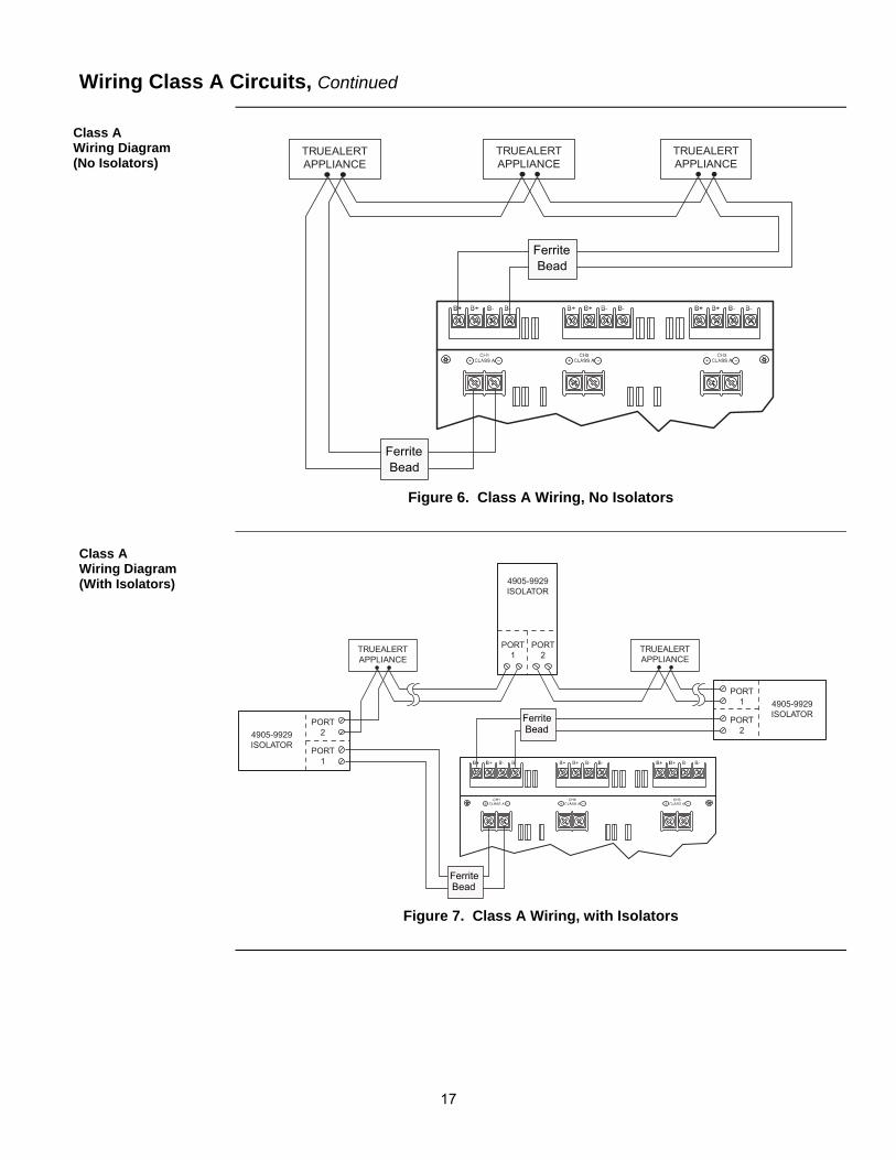
FigureTag FD9-336-03 TRUEALERTAPPLIANCE
TRUEALERTAPPLIANCE
TRUEALERTAPPLIANCE
FerriteBead
BeadFerrite
Figure 6. Class A Wiring, No Isolators
FigureTag FD9-336-04
PORT1 4905-9929
ISOLATORPORT
2
PORT1
4905-9929ISOLATOR
PORT2
PORT1
4905-9929ISOLATOR
PORT2
TRUEALERTAPPLIANCE
TRUEALERTAPPLIANCE
FerriteBead
FerriteBead
Figure 7. Class A Wiring, with Isolators
Wiring Class A Circuits, Continued
Class A Wiring Diagram (No Isolators)
Class A Wiring Diagram (With Isolators)
18
Only TrueAlert appliances and accessories (“Devices”) are allowed on these SLCs. Refer to Table 4 for a list of compatible TrueAlert devices and to the TrueAlert Device Installation Instructions for connection details.
Maximum 63 devices or 75 unit loads per channel, whichever comes first. See Table 4 for unit load details. The maximum number of visuals that can be synchronized on one circuit is 43 for fixed candela and 46 for multi-candela devices. The maximum resistance between any two visuals is 30 Ohms.
All wiring is supervised and power limited.
All wiring to be twisted pair – minimum 18 AWG (0.82 mm2), maximum 12 AWG (3.31 mm2). If shielded pair is used, the cable shield drain wire from all connected branches and taps must attach back to the (--) terminal of the circuit. Maximum two wires per terminal position.
Maximum alarm current is 3 A per SLC. Use alarm current for lowest rated appliance nameplate voltage. Total alarm current for all three SLCs plus all current draw from AUX power and option cards must not exceed 9 A.
Supervisory current is 0.20 mA per unit load.
Maximum length of all wire segments added together is 10,000 feet (3,048 m) per SLC. Maximum wire length from panel to any device is 2,500 feet (762 m).
The maximum wiring capacitance is 0.6 uF per channel. If shielded wire is used, you must add the capacitance of the drain wire to the conductor.
Voltage rating is 24 VDC, 2 V, peak-to-peak ripple maximum.
Maximum of six isolators between any appliance and SLC terminals. Maximum 12 isolators per SLC. Maximum 30 devices connected directly to any isolator terminal pair.
If notification appliances on a given Class B circuit are to be used for multiple notification zones for partial evacuation (selective signaling), then the NAC riser must be installed in accordance with the Survivability From Attack by Fire Requirements in NFPA 2002 ED. Section 6.9.4. One or more of the following should be used: 2 hour rated cable assembly A 2 hour rated shaft or enclosure 2 hour rated stairwell in building fully sprinklered in accordance with NFPA 13 The table below shows the maximum wire branch lengths for various alarm loads.
Table 7. Maximum SLC Wire Branch Length Based on Appliance Current Load
Distance in Feet (Meters) to the Last Appliance Alarm Current 18 AWG (0.82 mm2) 14 AWG (2.08 mm2) 12 AWG (3.31 mm2)
0.11 A 1,058 ft (322 m) 2,500 ft (762 m) 2,500 ft (762 m)
0.25 A 471 ft (144 m) 1,328 ft (405 m) 2,169 ft (661 m)
0.50 A 241 ft (73 m) 669 ft (204 m) 1,089 ft (332 m)
0.75 A 164 ft (50 m) 450 ft (137 m) 730 ft (223 m)
1.00 A 125 ft (38 m) 340 ft (104 m) 550 ft (168 m)
1.25 A 102 ft (31 m) 274 ft (84 m) 442 ft (135 m)
1.50 A 87 ft (27 m) 230 ft (70 m) 370 ft (113 m)
2.00 A ― 175 ft (53 m) 280 ft (85 m)
2.50 A ― 142 ft (43 m) 226 ft (69 m)
Wire Distances Based on 2.0 V Line Drop
Wiring Class B Circuits
Class B Guidelines
19
Continued on next page
20
The table below shows the maximum SLC wire branch length based on supervision communications.
Table 8. Maximum SLC Wire Branch Length Based on Supervision Communications
Distance in Feet (Meters) to the Last Appliance
Unit Load Range 18 AWG (0.82 mm2) 14 AWG (2.08 mm2) 12 AWG (3.31 mm2)
1 658 ft (201 m) 1,681 ft (512 m) 2,500 ft (762 m)
2 to 3 602 ft (183 m) 1,536 ft (468 m) 2,500 ft (762 m)
4 to 7 514 ft (157 m) 1,310 ft (399 m) 2,086 ft (636 m)
8 to 13 422 ft (129 m) 1,073 ft (327 m) 1,709 ft (521 m)
14 to 20 350 ft (107 m) 887 ft (270 m) 1,411 ft (430 m)
21 to 30 282 ft (86 m) 712 ft (217 m) 1,131 ft (345 m)
31 to 40 237 ft (72 m) 595 ft (181 m) 944 ft (288 m)
41 to 50 204 ft (62 m) 511 ft (156 m) 811 ft (247 m)
51 to 60 180 ft (55 m) 449 ft (137 m) 711 ft (217 m)
61 to 75 153 ft (47 m) 379 ft (116 m) 600 ft (183 m)
For Class B wiring with no isolators, T-Tapping is allowed. SLC wiring may be split multiple times to form SLC wiring branches. Maximum wire distance of each of these SLC branches from the panel to any device is the smaller of the values obtained from Table 7 and Table 8. Add the alarm loads of all of the devices on an SLC branch and apply to Table 7. Add the unit loads (see Table 4) of all the devices on an SLC branch and apply it to Table 8. Use of Table 7 and Table 8 requires all SLC wire branches join within 10 feet (3 m) of the panel. T-tap wire stubs are allowed on the SLC wire branches, but each tap must be less than 100 feet (30 m). FigureTag FD9-336-05
TRUEALERTAPPLIANCE
TRUEALERTAPPLIANCE
TRUEALERTAPPLIANCE
TRUEALERTAPPLIANCE
TRUEALERTAPPLIANCE
TRUEALERTAPPLIANCE
FerriteBead
Figure 8. Class B Wiring, No Isolators
Continued on next page
Wiring Class B Circuits, Continued
Class B Guidelines
Class B Wiring Diagram (No Isolators)
21
For Class B wiring with isolators, T-Tapping is allowed. SLC wiring may be split multiple times to form SLC wire branches. Maximum wire distance of each of these SLC branches from panel to any device is the smaller of the values obtained from Table 8 and the Equation 1 shown below. Add the alarm loads of all the devices on an SLC wire branch and apply to Equation 1. Add the unit loads (see Table 4 for unit loads) for all devices on an SLC wire branch and the number of isolators and apply to Table 8. Use of Table 8 requires that all SLC wire branches join within 10 feet (3 m) of the panel. T-tap wire stubs are allowed on the SLC wire branches, but each tap must be less than 100 feet (30 m). Equation 1: Maximum SLC Wire Branch Length Based on Appliance Alarm Current Load Feet = 10 + (2V – (2.5A * 10 * 2 * (res/ft) * 0.1(#isolators)(branch alarm amps)
Supervision must be provided if the auxiliary power circuit is to be wired as a power-limited circuit. In order to connect a circuit using power-limited wiring, the devices being powered must all be addressable, or a UL Listed EOL relay must be used to supervise the circuit. Refer to the figure below for wiring directions for the EOL relay.
2098-9739END OF
LINE RELAY
TO AUX POWER
RED BLACK
LAST IDCDEVICE
YELLOW
RESISTORIDC
Figure 10. Auxiliary Power-to-Power Limited Wiring The AUX Power output is defined by UL as Special Applications, and is compatible with these devices: 2088-Series relays and door handlers 2098-Series four-wire smoke detectors 2190-Series monitor and signal ZAMs 4090-Series IDNet ZAMs 4098-Series four-wire smoke detectors and duct detectors 2190-9039 Printer 4190-9050/9051, 4-20 mA ZAMs 4603-9101 LCD Annunciator
Wiring AUX Power
Wiring Diagram to Connect AUX Power to Power Limited Wiring
AUX Compatible Devices
Note: The 2098-9739 Relay is used as an example. Other UL Listed 24 VDC EOL relays can be used, depending on the application.
23
The system trouble indicators consist of a bank of five yellow LEDS (refer back to Figure 1 for their location on the TPS). These LEDs are used to signal various trouble conditions on the TPS and its SLCs. Only one trouble at a time is shown. You can step through all of the troubles present on the TPS or its SLCs using the Trouble Scroll Pushbutton. This pushbutton is shown in Figure 1 and is located just to the right of LEDs A through E. Notes:
Any trouble indication that applies to a specific SLC channel has the corresponding LED (CH1 through CH3) for that channel lit.
The Trouble Scroll Pushbutton allows an operator to scroll through multiple troubles.