96
| Date post: | 29-Oct-2014 |
| Category: |
Documents |
| Upload: | alexey-shvatsky |
| View: | 90 times |
| Download: | 7 times |


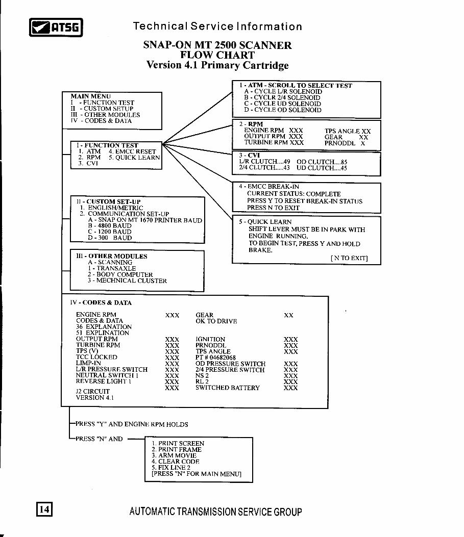


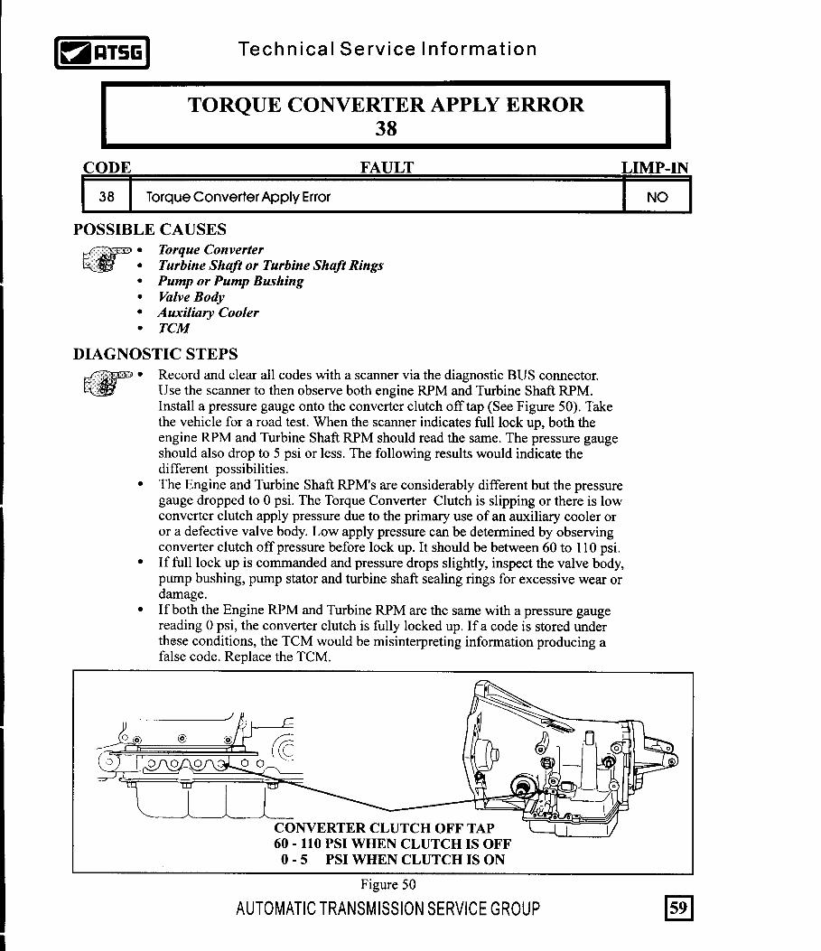
A "NO MODULES RESPONDING" may be understood as a module on the CCD BUS System (in this case the TCM) is not responding to the request by the scanner for data. This problem may be defined or interpreted in several ways depending upon the scanner being used. For example, with the Snap-On MT2500 scanner, the message "No Module Responding" may appear on the Main Menu or it just does not display the "CCD Systems" as an option. At this time the Technician should verify the the ignition is in the ON position. If it is not, this may be the problem. Turn the ignition to the ON position. If the ignition is in the ON position, the problem may be that controller has lost its battery feed. Refer to step number 1 on this page. With OTC Monitor 4000, the scanner displays the word EATX in the screen along side a number "1". The system can be entered by pressing the number "1" and then the "enter" button on the front panel . If the EATX controller (TCM) does not respond, an asterisk (*) is displayed rather than the number 1 denying any access to the controller. At this time the technician should verify that the key is turned to the ON position. If it is not this may be the problem. Turn the ignition to the ON position. If the ignition is in the ON position and the asterisk does not change to a number 1, press number 4 for "Sys. Info" or 2 for "Bus Monitor" (These selections vary depending on which cartridge is being used). If a BUS Failure message appears, refer to the BUS Failure Section on page 21. If the list of all possible controllers on the BUS System appears on the scanner screen and the EATX controller (TCM) still has an asterisk next to it, the problem may be that controller has lost its battery feed. Go to step number 1 on this page.
AUTOMATIC TRANSMISSION SERVICE GROUP
Technica l Serv ice In format ion
NO MODULES RESPONDING
NO MODULES RESPONDING:
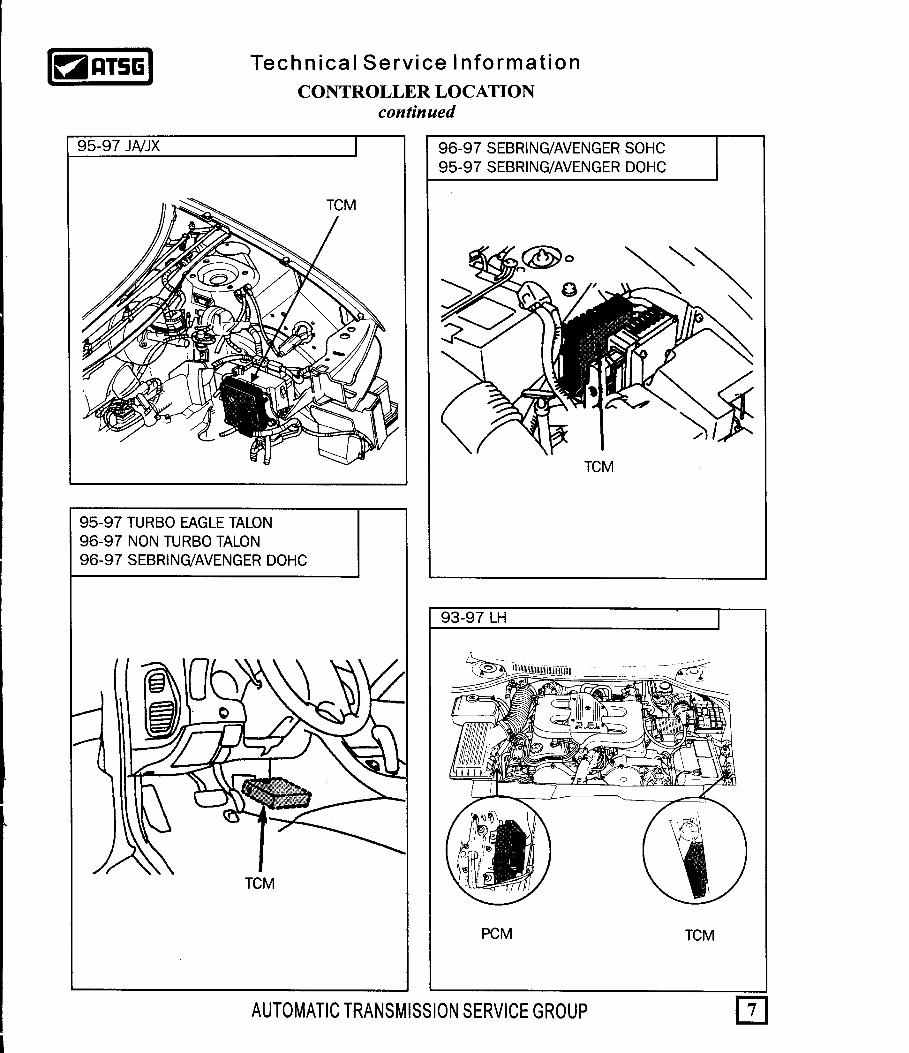
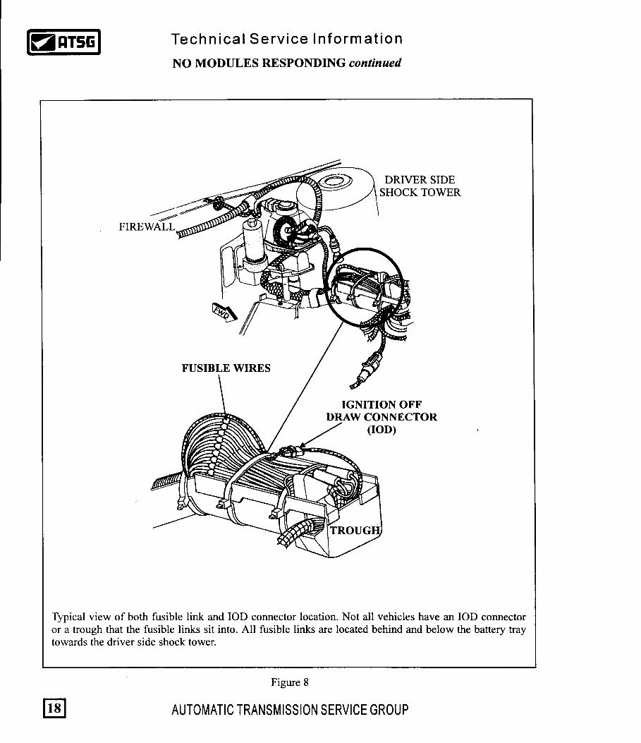
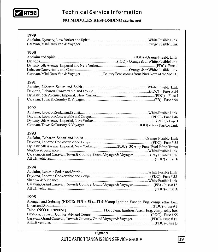
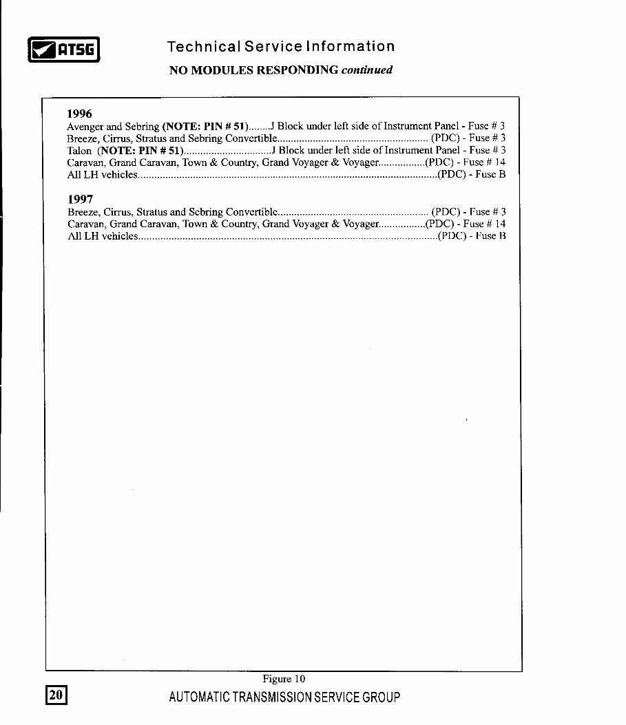
1. Locate the TCM (See pages 6 and 7) and carefully unplug the 60 way connector.2. With a DVOM set to DC volts, check for battery voltage on the J11 circuit at pin 56 as shown in Figure 7. If battery voltage is seen, go to the next step. If battery voltage is not seen, go to step 4.3. If battery voltage is seen, keep the meter attached to pin 56 and begin to wiggle the wiring harness from the controller to the battery. While doing so, constantly monitor the meter to see if voltage is lost at any time during the wiggle test. If so, repair the break in the wire. If voltage is not lost, plug the 60 way connector back into the controller and attempt to re-enter the scanner. If you can, there was a bad connection to start with. If you still can not, the controller is bad and will need to be replaced. 4. If battery voltage is not seen, a fuse or a fusible wire may be blown. Fusible wires are color coded and can usually be found below and between the battery and driver side spring tower as shown in Figure 8. Refer to Figures 9 and 10 for fusible wire color or fuse number.
Figure 7
17

This complaint is not to be confused with a fault code 19. Fault code 19 is a BUS communication error where the transaxle computer (TCM) is not receiving information from the engine computer (SMEC). Refer to the index for the page number where this problem is covered in further detail. A BUS failure or BUS inactive problem is when the BUS system itself is inoperative and the scanner cannot communicate to any of the computers on the BUS system. The most common reason for this complaint is a bad connection at either the transaxle controller or the body controller or both. First unplug the TCM (For controller locations, refer to pages 6 and 7). Clean the terminal side of the 60 way connector and plug the controller back in and verify scanner communication. If there is still a BUS failure problem and the vehicle is NOT equipped with a body computer, the TCM is either bad and will need to be replaced or there is low battery voltage feeding the controller at either pin 11 or 56 (Refer to pages 19 and 20 for battery feed location and pages 3-5 for preliminary electrical checks). If the vehicle is equipped with a body computer (See Figure 11 for body controller location), unplug and clean its connector. After plugging it back in, verify scanner communication. If a BUS failure still remains, the body computer may need to be replaced. There is not a sure method in determining which controller is causing the BUS failure. When a vehicle is not equipped with a body computer, it is safe to determine that the TCM is bad causing the concern. If it is equipped with a body computer, it could be either controller. However, the body computer would be the most likely cause of the problem. The reason is that the body controller is the computer controlling the voltage in the BUS system. So if there is a BUS failure, the most likely candidate would be the controller responsible for putting the voltage into the BUS system. The majority of vehicles are equipped with both a body controller and a TCM. Vehicles NOT equipped with a body computer are, all Spirit and Acclaim vehicles, all 1989 and 1990 Vans and some Lebarons. In these cases, the EATX controller would be suspect.
21
Technica l Serv ice In format ion
BUS FAILURE or BUS INACTIVE
AUTOMATIC TRANSMISSION SERVICE GROUP
BUS FAILURE or INACTIVE: BODY CONTROLLERThe body controllers in vans is located behind the center of the dash left of the steering column. Passenger cars have the body controller located behind the passenger side kick panel (See Figure 11).
Body Controller Location on Passenger Cars
behind right kick panel
Body Controller Location on Vans behind center of dash
Figure 11

41TE & 42LE OBDII DIAGNOSTIC TROUBLE CODE LIST
FaultCode
Description
Battery was disconnected
15
Engine Speed Sensor Circuit
19
20
21
22
23
24
25
26
14
Internal TCM
Internal TCM
Internal TCM
Transmission Relay OutputAlways On
Transmission Relay OutputAlways Off
YES
YES
YES
YES
P1767
P1768
BUS Communication withEngine Module YES
Switched Battery
OD Pressure SwitchSensor Circuit
YES(Pre-96)
11
12
13
16
17
18
YES
YES
YES
YES
NO
YES
YES
YES
YES
NO
YES
YES
YES
YES
YES
YES
P0700
P1792
P0700
P0605
P0605
P0725
P0600
P1765
P1783
P1781
P1782
P1784
P1785
P1780
YES
YES*
YES
YES(Pre-96)
N/A
N/A
N/A
NO
2/4 Pressure SwitchSensor Circuit
2/4 & OD Pressure SwitchSensor Circuit
L/R Pressure Switch Circuit
LR & OD Pressure SwitchSensor Circuit
L/R & 2/4 Pressure SwitchSensor Circuit
YES(Pre-96)
N/A(96/97)
YES(Pre-96)
N/A(96/97)
Internal TCM
Limp-in SetMIL IlluminationLate Models Only
OBDII Codes
YES(Pre-96)
N/A(96/97)
28
27
29
All Pressure Switch Circuits N/A P1786
Check Shifter Signal
Throttle Position Sensor
NO
NO
NO
YES
P0705
P0120*
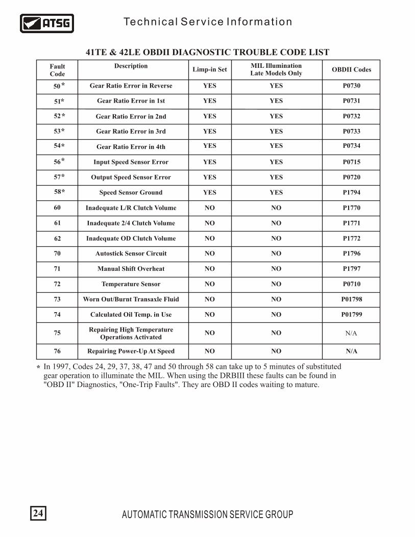
In 1997, Codes 24, 29, 37, 38, 47 and 50 through 58 can take up to 5 minutes of substituted gear operation to illuminate the MIL. When using the DRBIII these faults can be found in "OBD II" Diagnostics, "One-Trip Faults". They are OBD II codes waiting to mature.
*
Technica l Serv ice In format ion
AUTOMATIC TRANSMISSION SERVICE GROUP22

FaultCode
Description
36
44
45
46
47
48
35 Loss of Prime
Solenoid Switch ValveStuck in the TCC Position
TCC Apply Failure
2/4 Solenoid Circuit
31
37
38
42
YES YES
NO
YES
NO
YES
YES
NO
P1787
P1791
P1775
P0755
P0783
P1795
P1776
P1793
NO
*
NO YES
YES
NO
NO
Internal TCM
3-4 Shift Abort
Solenoid Switch ValveStuck in the L/R Position
TRD Link Communication Error
YES
NO
OD Hydraulic PressureSwitch Circuit
Limp-in SetMIL IlluminationLate Models Only
32 YES YES P17882/4 Hydraulic Pressure
Switch Circuit
33 YES YES P17892/4 & OD Hydraulic Pressure
Switch Circuit
Fault Immediately After Shift NONO P1790
*
* YESNO P0740
LR Solenoid Circuit41 YESYES P0750
OD Solenoid Circuit43 YESYES P0760
UD Solenoid Circuit YESYES P0765
* In 1997, Codes 24, 29, 37, 38, 47 and 50 through 58 can take up to 5 minutes of substituted gear operation to illuminate the MIL. When using the DRBIII these faults can be found in "OBD II" Diagnostics, "One-Trip Faults". They are OBD II codes waiting to mature.
OBDII Codes
41TE & 42LE OBDII DIAGNOSTIC TROUBLE CODE LIST
Technica l Serv ice In format ion
AUTOMATIC TRANSMISSION SERVICE GROUP 23
FaultCode
Description
56
70
71
72
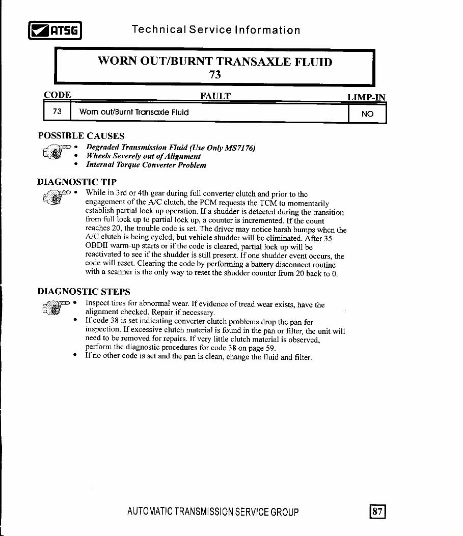
73
74
53
Output Speed Sensor Error
Speed Sensor Ground
Inadequate L/R Clutch Volume
50
57
58
61
YES YES
YES
NO
YES
P0730
P01798
N/A
NONO
NO
NOManual Shift Overheat
Repairing High TemperatureOperations Activated
NO
NO
Gear Ratio Error in Reverse
Limp-in SetMIL IlluminationLate Models Only
51 YES YESGear Ratio Error in 1st
52 YES YES P0732
Input Speed Sensor Error
*
* YESYES
60 NO
P1794
62 NO
P0731
Gear Ratio Error in 2nd
Gear Ratio Error in 3rd YES YES P0733
54 Gear Ratio Error in 4th YES YES P0734
YES YES P0715
*
*
*
*
*
*
P0720
Inadequate 2/4 Clutch Volume
Inadequate OD Clutch Volume
NO
NO
NO
P1770
P1771
P1772
Autostick Sensor Circuit
75
76
NO
NO
NO
NO
NO
NO
NO
NO
P1796
P1797
P0710
P01799
Temperature Sensor
Worn Out/Burnt Transaxle Fluid
Calculated Oil Temp. in Use
Repairing Power-Up At Speed
* In 1997, Codes 24, 29, 37, 38, 47 and 50 through 58 can take up to 5 minutes of substituted gear operation to illuminate the MIL. When using the DRBIII these faults can be found in "OBD II" Diagnostics, "One-Trip Faults". They are OBD II codes waiting to mature.
OBDII Codes
N/A
41TE & 42LE OBDII DIAGNOSTIC TROUBLE CODE LIST
Technica l Serv ice In format ion
AUTOMATIC TRANSMISSION SERVICE GROUP24


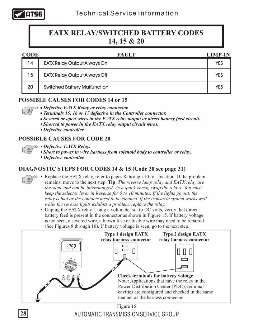
EATX RELAY/SWITCHED BATTERY CODES14, 15 & 20
CODE FAULT LIMP-IN
EATX Relay Output Always On
EATX Relay Output Always Off
Switched Battery Malfunction
14
15
20
YES
YES
YES
Defective EATX Relay or relay connector. Terminals 15, 16 or 17 defective in the Controller connector. Severed or open wires in the EATX relay output or direct battery feed circuit. Shorted to power in the EATX relay output circuit wires. Defective controller
POSSIBLE CAUSES FOR CODES 14 or 15
Replace the EATX relay, refer to pages 8 through 10 for location. If the problem remains, move to the next step. Tip: The reverse lamp relay and EATX relay are the same and can be interchanged. As a quick check, swap the relays. You must keep the selector lever in Reverse for 5 to 10 minutes. If the lights go out, the relay is bad or the contacts need to be cleaned. If the transaxle system works well while the reverse lights exhibits a problem, replace the relay. Unplug the EATX relay. Using a volt meter set to DC volts, verify that direct battery feed is present in the connector as shown in Figure 15. If battery voltage is not seen, a severed wire, a blown fuse or fusible wire may need to be repaired (See Figures 8 through 10). If battery voltage is seen, go to the next step.
DIAGNOSTIC STEPS FOR CODES 14 & 15 (Code 20 see page 31)
Figure 15
Technica l Serv ice In format ion
AUTOMATIC TRANSMISSION SERVICE GROUP28
POSSIBLE CAUSES FOR CODE 20
Defective EATX Relay. Short to power in wire harness from solenoid body to controller or relay. Defective controller.
Type 1 design EATX relay harness connector
Type 2 design EATXrelay harness connector
Check terminals for battery voltageNote: Applications that have the relay in the Power Distribution Center (PDC), terminalcavities are configured and checked in the samemanner as the harness connector.


31AUTOMATIC TRANSMISSION SERVICE GROUP
Technica l Serv ice In format ion
EATX RELAY/SWITCHED BATTERY CODES14, 15 & 20 continued
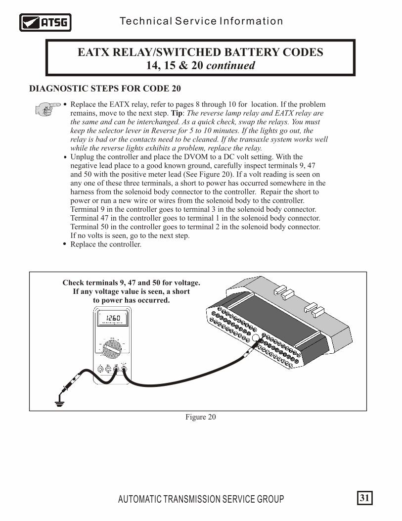
DIAGNOSTIC STEPS FOR CODE 20
Replace the EATX relay, refer to pages 8 through 10 for location. If the problem remains, move to the next step. Tip: The reverse lamp relay and EATX relay are the same and can be interchanged. As a quick check, swap the relays. You must keep the selector lever in Reverse for 5 to 10 minutes. If the lights go out, the relay is bad or the contacts need to be cleaned. If the transaxle system works well while the reverse lights exhibits a problem, replace the relay. Unplug the controller and place the DVOM to a DC volt setting. With the negative lead place to a good known ground, carefully inspect terminals 9, 47 and 50 with the positive meter lead (See Figure 20). If a volt reading is seen on any one of these three terminals, a short to power has occurred somewhere in the harness from the solenoid body connector to the controller. Repair the short to power or run a new wire or wires from the solenoid body to the controller. Terminal 9 in the controller goes to terminal 3 in the solenoid body connector. Terminal 47 in the controller goes to terminal 1 in the solenoid body connector. Terminal 50 in the controller goes to terminal 2 in the solenoid body connector. If no volts is seen, go to the next step. Replace the controller.
Check terminals 9, 47 and 50 for voltage.If any voltage value is seen, a short
to power has occurred.
Figure 20


With a DVOM set to DC volts, using the positive meter lead carefully back probe wire 45 at the TCM for 89-95 3.3 and 3.8L applications. For all LH vehicles and 96 and later 3.3 and 3.8L applications, back probe wire 6 at the TCM. Place the negative meter lead to a good known ground (See Figure 21). With the key on and engine off, approximately an 5 to 9 volt pulse should be seen as the crank shaft is turned by hand. If a voltage pulse is observed, the TCM needs to be replaced. If no volts are observed, go to the next step. Locate the crank sensor as shown in Figure 26. Unplug both the crank sensor and the TCM. For 89-95 3.3 and 3.8L applications perform a continuity check across terminal 1 in the crank sensor connector to terminal 45 in the TCM connector . For all LH vehicles and 96 and later 3.3 and 3.8L, check across terminal 3 in the crank sensor connector to terminal 6 in the TCM connector (See Figure 27). If there is no continuity, repair or replace the wire.
AUTOMATIC TRANSMISSION SERVICE GROUP
Technica l Serv ice In format ion
ENGINE SPEED SENSOR CIRCUIT CODE 18 continued
TCM RPM CHECK PROCEDURE (3.3 & 3.8L & LH Vehicles)
35
Crank Sensor
Crank Sensor
Figure 26
Vehicle HarnessConnector View
Figure 27
DifferentialCover
42LE41TE
3
1
Mis-adjusted sensor depth makes for a no start or quit running when hot.


2
3
1
2
3
1
Technica l Serv ice In format ion
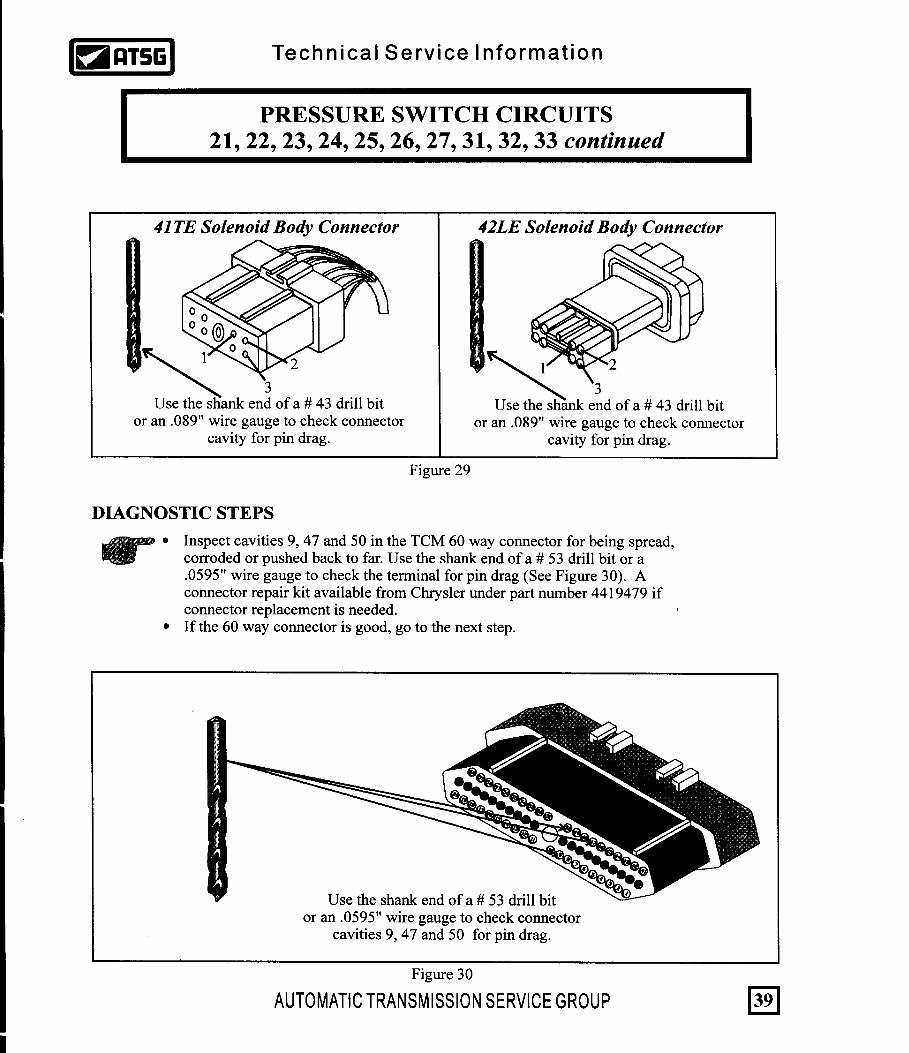
PRESSURE SWITCH CIRCUITS21, 22, 23, 24, 25, 26, 27, 31, 32, 33 continued
AUTOMATIC TRANSMISSION SERVICE GROUP40
A continuity check should be made across the following appropriate wire from the solenoid connector to the TCM connector (See Figure 31):
PRESSURE SWITCH SOLENOID BODY TCM CONNECTOR CONNECTOR
Low/Reverse Pressure Switch Wire - 2 50 2/4 Pressure Switch Wire - 1 47 Overdirve Pressure Switch Wire - 3 9
DIAGNOSTIC STEPS
Figure 31
Special note: 2/4 & L/R Pressure Switch codes could occur due to incorrect placement of check balls in the valve body.

Technica l Serv ice In format ion
PRESSURE SWITCH CIRCUITS21, 22, 23, 24, 25, 26, 27, 31, 32, 33 continued
AUTOMATIC TRANSMISSION SERVICE GROUP 41
Another method which may be employed to verify the wiring integrity for each pressure switch circuit requires both the solenoid body and the TCM to be plugged in. Place the ignition to the ON position. Do not start the vehicle. With a DVOM set to DC volts, place the negative meter lead to the negative battery post. With the positive meter lead, carefully back probe wires 9, 47 and 50 (See Figure 32). Each wire should show battery voltage. Special Note: This method should only be employed when pressure switch codes alone are present. Other codes such as a solenoid code may cause the control to default to a limp mode status with just the ignition turned ON. Voltage would then not be observed at pins 9, 47 and 50 providing a false test. If any one of the wires do not show voltage during this test, there is a break in that wire from the solenoid body to the TCM. Repair the wire. If voltage is seen on all three wires, inspect the solenoid body. To check the solenoid body for a 41TE see Figure 33. To inspect a 42LE solenoid body, see Figure 34. If the pressure switch codes still set with a good known solenoid body and all the wiring has been inspected, change the TCM. Note: Only on rare occasions has a bad valve body provided enough of a cross leak that it may stroke a pressure switch when it should not be stroked causing the code. A worn sleeve in the pressure regulator valve may also be a problem with pressure too high and no valve body gaskets. Problem occurs at high throttle when hot. A valve body change may correct the problem. If it doesn't, change the TCM.
DIAGNOSTIC STEPS
1 10 11 20
41 50 51 60
Figure 32

Technica l Serv ice In format ion
AUTOMATIC TRANSMISSION SERVICE GROUP42
Figure 33
PRESSURE SWITCH CONNECT OHMMETER LEADS TO PIN
2-4
1 & GROUND (Body Base)
2 & GROUND (Body Base)
3 & GROUND (Body Base)
L-R
O.D.
L-R PRESSURE SWITCH PASSAGE
OHM METER SHOULD READ "NO CONTINUITY" WITH NO AIR APPLIED TO THE PRESSURE SWITCH. OHM METER SHOULD READ LESS THAN "3" OHMS .
WITH 50 PSI OF AIR PRESSURE APPLIED TO THE PRESSURE SWITCH.
OD PRESSURE SWITCH PASSAGE
2/4 PRESSURE SWITCH PASSAGE
41TE SOLENOID BODYRESISTOR AND PRESSURE SWITCH CHECK
OHM TEST
PRESSURE SWITCH TEST
EACH PRESSURE SWITCH HAS ITS OWN RESISTOR IN THE CIRCUIT WHICH RANGE BETWEEN APPROXIMATELY 270-330 OHMS @ 68° F
EACH RESISTOR SIMILAR IN RESISTANCE. FOR EXAMPLE: 2 MEASURE 270 AND 1 MEASURES 330 - NO GOOD
RESISTOR CONNECT OHMMETER LEADS TO PINS
2-4 4 & 1
4 & 2
4 & 3
L-R
O.D.
2 1 8 7
3 4 5 6

42LE SOLENOID BODYRESISTOR AND PRESSURE SWITCH CHECK
4 5 6
7812
3
OHM TEST
PRESSURE SWITCH TEST
EACH PRESSURE SWITCH HAS ITS OWN RESISTOR IN THE CIRCUIT WHICH RANGE BETWEEN APPROXIMATELY 270-330 OHMS @ 68° F
EACH RESISTOR SIMILAR IN RESISTANCE. FOR EXAMPLE: 2 MEASURE 270 AND 1 MEASURES 330 - NO GOOD
RESISTOR CONNECT OHMMETER LEADS TO PINS
2-4 4 & 1
4 & 2
4 & 3
L-R
O.D.
PRESSURE SWITCH CONNECT OHMMETER LEADS TO PIN
2-4
L-R
O.D.
L-R PRESSURE SWITCH
2-4 PRESSURE SWITCH O.D. PRESSURE SWITCH
OHM METER SHOULD READ "NO CONTINUITY" WITH NO AIR APPLIED TO THE PRESSURE SWITCH. OHM METER SHOULD READ LESS THAN "3" OHMS .
WITH 50 PSI OF AIR PRESSURE APPLIED TO THE PRESSURE SWITCH.
Technica l Serv ice In format ion
AUTOMATIC TRANSMISSION SERVICE GROUP 43
Figure 34
1 & GROUND (Body Base)
2 & GROUND (Body Base)
3 & GROUND (Body Base)


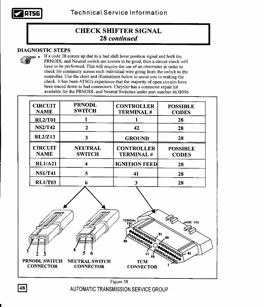
A PRNODL or Neutral Safety switch malfunction (89-94 41TE). A malfunctioning Transmission Range Sensor (95 and up 41 TE & 42RE). Plastic cam on manual lever assembly on the valve body broken. Defective connectors. Severed or shorted wiring from switches to TCM.
Diagnostic steps for 1995 and later 41TE's & all LH vehicles with a TRS, refer to page 50.
Technica l Serv ice In format ion
CHECK SHIFTER SIGNAL28
CODE FAULT LIMP-IN
Check Shifter Signal28 NO
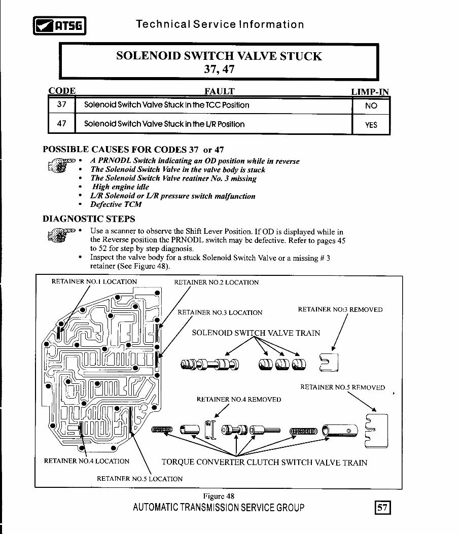
POSSIBLE CAUSES
AUTOMATIC TRANSMISSION SERVICE GROUP 45
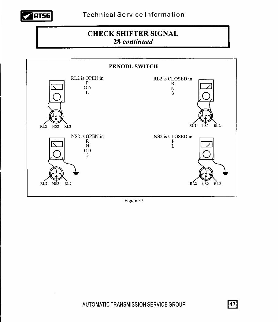
DIAGNOSTIC STEPS for 1989-1994 41TE with PRNODL & Neutral Switch A scanner can be used to observe the OPEN/CLOSED state of both the Reverse Light 1 & 2 and the Neutral Switch 1 & 2 circuits. This can be especially helpful in determining which exact circuit is malfunctioning. Refer to Figure 35 for both the OP/CL chart as well as the RL and NS circuit identification.
SAFTEY NEUTRALSWITCH
RL2
RL1
NS2
NS1
RL2
RL1
PRNODL
T1, T2 TRANSITION CODES MAY APPEAR BETWEEN GEAR RANGE CHANGES.AN "I" OR "?" WILL APPEAR ON SCANNERS IF INVALID COMBINATION OCCURS.
NS1RL1NS2RL2
ClosedOpenClosedOpen
OpenOpenOpenClosed
ClosedOpenOpenClosed
OpenClosedOpenClosed
OpenOpenClosedOpen
OpenClosedOpenOpen
Circuit P R N OD D L
Figure 35
* *RL2 can also be open


Technica l Serv ice In format ion
CHECK SHIFTER SIGNAL28 continued
AUTOMATIC TRANSMISSION SERVICE GROUP50
DIAGNOSTIC STEPS FOR 1995 AND LATER VEHICLES WITH A TRS A scanner can be used to observe the OPEN/CLOSED state of the C1/T41, C2/T42, C3/T3 and the C4/T1 circuits. This can be especially helpful in determining which exact circuit is malfunctioning. Refer to Figure 40 for the OPEN/CLOSED status chart and circuit identification.
53 41
6 7 8 9 10
1
6
5
10
CAVITY COLOR FUNCTION
1 WT
DB/BK *
VT *
BK/LG
VT
VT/WT
BR/YL
VT/BK
LG/BK TRS T1 SENSE
TRS T3 SENSE
TRS T42 SENSE
TRS T41 SENSETo PCM
(Terminal 5 signals the TCM)
FUSED IGNITIONSWITCH OUTPUT
SPEED SENSORGROUND
REVERSE LAMPSENSE
TRANS. TEMP.SENSOR SIGNAL
PARK/NEUT. POSITION
SWITCH SENSE
3
4
5
6
7
8
9
10
* 1996-97 LH
RANGE
P
R R
N N
OD D
23
11
P CL CL
CL
CL CL
CL
CLCL
CL
CL
CL
CL
OP
OP OP
OP
OPOP
OP OP
OP
OP
OP
OP
T42 (C2) T41 (C1) T3 (C3) T1 (C4)
OP = SWITCH IS OPENCL = SWITCH IS CLOSED
41TE 42LE
TRANSMISSION RANGE SENSORTRS
Figure 40

Technica l Serv ice In format ion
CHECK SHIFTER SIGNAL28 continued
DIAGNOSTIC STEPS
AUTOMATIC TRANSMISSION SERVICE GROUP 51
Figure 41
Once the circuit which malfunctioned has been identified, a continuity check should be made on that circuit. Use the chart found in Figure 41 to assist in identifying the specific circuit or circuits in question. For example, if the scanner reveals that the T3 (C3) circuit does not close when the selector lever is placed in Park, 3 or 1, that specific circuit will need to be checked. In the chart below circuit T3 is the wire which runs from the number eight cavity in the TRS connector to the number three cavity in the TCM connector.
1
6
5
10
213
4
6
1
78
942
5
11
41
45
43
4647
48-49
51
44
5253
5455
5657
5859
60
50
12
13
15
10
1617
1819
20
14
CIRCUITNAME
CONTROLLERTERMINAL #
POSSIBLE CODES
41
8
1C4/T01
TRANSMISSIONRANGE SENSOR
28
C1/T41
C3/T03
5
9C2/T42
3
42
28
28
7 28
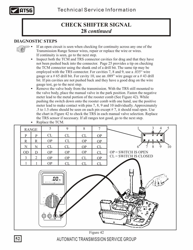
If an open circuit is seen when checking for continuity across any one of the Transmission Range Sensor wires, repair or replace the wire or wires. If continuity is seen, go to the next step. Inspect both the TCM and TRS connector cavities for drag and that they have not been pushed back into the connector. Page 25 provides a tip on checking the TCM connector using the shank end of a drill bit. The same tip may be employed with the TRS connector. For cavities 7, 8 and 9, use a .035“ wire gauge or a # 65 drill bit. For cavity 10, use an .089” wire gauge or a # 43 drill bit. If pin cavities are not pushed back and they have a good drag on the wire gauge test, go to the next step. Remove the valve body from the transmission. With the TRS still mounted to the valve body, place the manual valve in the park position. Fasten the negative meter lead to the metal portion of the rooster comb (See Figure 42). While pushing the switch down onto the rooster comb with one hand, use the positive meter lead to make contact with pins 7, 8, 9 and 10 individually. Approximately .5 to 1.5 ohms should be seen on each pin except # 7, it should read open. Use the chart in Figure 42 to check the TRS in each manual valve selection. Replace the TRS sensor if necessary. If all ranges test good, go to the next step. Replace the TCM.
Technica l Serv ice In format ion
CHECK SHIFTER SIGNAL28 continued
AUTOMATIC TRANSMISSION SERVICE GROUP52
DIAGNOSTIC STEPS
Figure 42
53 41
6 7 8 9 10
RANGE
P
R R
N N
OD D
23
11
P CL CL
CL
CL CL
CL
CLCL
CL
OP
CL
OP
OP
CL OP
OP
OPOP
OP OP
OP
OP
CL
OP
9 8 7
OP = SWITCH IS OPENCL = SWITCH IS CLOSED
5

41505160
1101120
Compare the TPS voltage seen through a scanner display to a volt meter attached to the number 12 TPS signal wire at the TCM (See Figure 43). With the engine off, place the ignition to the “ON” position. At closed throttle, approximately .50 to .78 volts should be observed. As the throttle is opened the voltage should increase proportionally. When wide open throttle is reached, approximately 3.8 to 4.0 volts should be seen. NOTE: Both readings should be relatively the same however, the TPS voltage change observed through the scanner will be slightly delayed to that seen on the volt meter. If the voltage change observed through the volt meter is correct while the scanner provides unusual and incorrect readings, the TCM will need to be replaced. If both the scanner and volt meter reveal a no volt reading, a fixed volt reading, an erratic or incorrect volt reading, go to the next step.
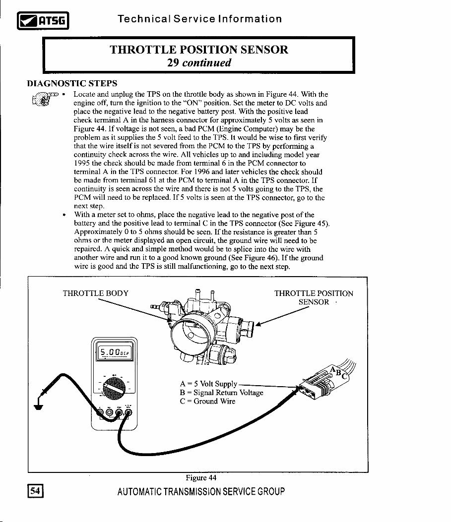
Throttle Position Sensor Corroded or defective throttle position sensor connector (or installed backwards) Open throttle position sensor ground wire Open or shorted signal return wire Open or shorted 5 volt power wire Corroded or defective TCM connector Corroded or defective PCM connector Defective TCM Defective PCM
Technica l Serv ice In format ion
THROTTLE POSITION SENSOR29
CODE FAULT LIMP-IN
Throttle Position Sensor29 NO
POSSIBLE CAUSES
DIAGNOSTIC STEPS
AUTOMATIC TRANSMISSION SERVICE GROUP 53
Figure 43
2.50DCV
Carefully probe the# 12 wire in the
TCM


15
16
17
20
19
60
59
11
8
5758
9
47
50
TRANSAXLE CONTROLLER
IGNITION
CRANK
GROUNDSOLENOID BODY
3
1
2
7
8
6
5
OD Press Sw
2/4 Press Sw
L/R Press Sw
L/R SOLENOID
2/4 SOLENOID
OD SOLENOID
UD SOLENOID
EATX RELAY
BATTERYVOLTAGE
SPLICE
Breaks can occurbelow the splice
4
Technica l Serv ice In format ion
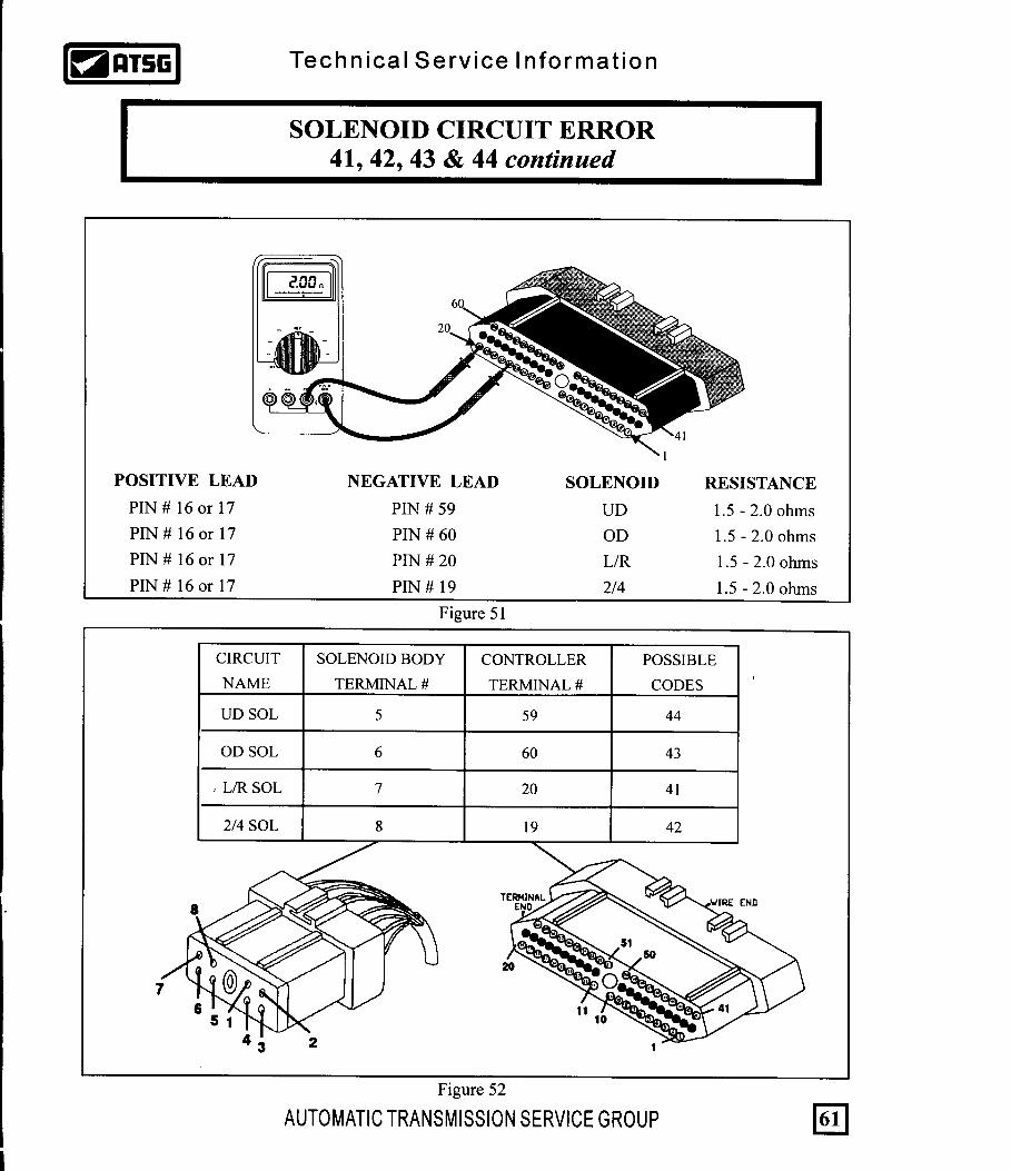
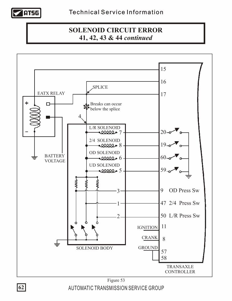
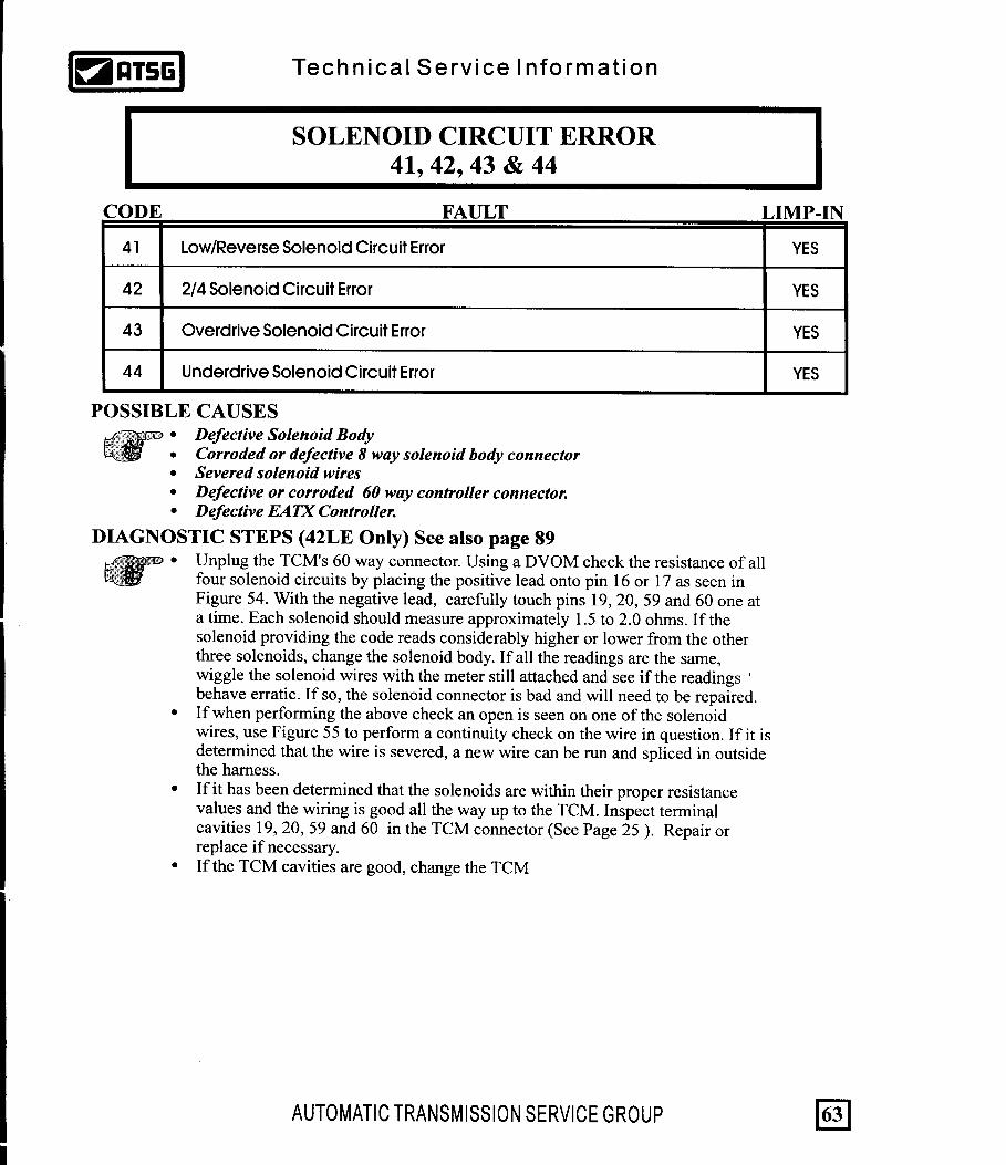
SOLENOID CIRCUIT ERROR 41, 42, 43 & 44 continued
Technica l Serv ice In format ion
AUTOMATIC TRANSMISSION SERVICE GROUP
Figure 53
62


213
4
6
1
78
942
5
11
41
45
43
4647
48-49
51
44
5253
5455
5657
5859
60
50
12
13
15
10
1617
1819
20
14
213
4
6
1
78
942
5
11
41
45
43
4647
48-49
51
44
5253
5455
5657
5859
60
50
12
13
15
10
1617
1819
20
14
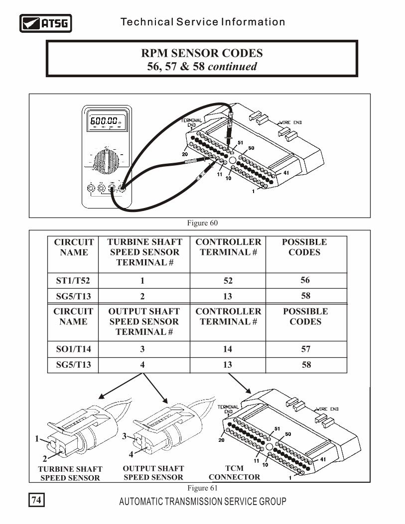
CIRCUITNAME
TURBINE SHAFTSPEED SENSOR
TERMINAL #
OUTPUT SHAFTSPEED SENSOR
TERMINAL #
CONTROLLERTERMINAL #
POSSIBLE CODES
CIRCUITNAME
CONTROLLERTERMINAL #
POSSIBLE CODES
SG5/T13
14
4
ST1/T52 1
58SG5/T13 2
13
SO1/T14 3
13
52 56
57
58
OUTPUT SHAFTSPEED SENSOR
TURBINE SHAFTSPEED SENSOR
2
1
4
3
TCMCONNECTOR
Figure 60
Figure 61
AUTOMATIC TRANSMISSION SERVICE GROUP74
Technica l Serv ice In format ion
RPM SENSOR CODES 56, 57 & 58 continued
Technica l Serv ice In format ion


Technica l Serv ice In format ion
INADEQUATE CLUTCH VOLUME 60, 61 & 62
CODE FAULT LIMP-IN
Inadequate L/R Clutch Volume
Inadequate 2/4 Clutch Volume
Inadequate OD Clutch Volume
60
61
62
NO
NO
NO
POSSIBLE CAUSES
Technica l Serv ice In format ion
High Line Pressure Cross Leaks Clutch Pack Mis-assembly Broken Snap Ring Bad alternator (spike voltage), Bad battery or Bad TCM
DIAGNOSTIC TIPSClutch Volume Index (CVI) is a calculated numerical value to indicate how much volume of transmission fluid was needed to apply a friction element without stroking the accumulator piston. The L/R, 2/4 and OD clutch elements are continuously monitored and learned for adaptive controls. As the friction material wears, the volume of fluid needed to apply the element increases. The following numerical values are Chrysler's suggested acceptable tolerances for A-604 clutch volumes:L/R: 35 to 83 2/4: 20 to 77OD: 75 to 150 UD: 24 to 70If the battery has been disconnected, some models will loose the learned CVI values. In such cases, the EATX Controller will go to a default setting until the new CVI values are learned. The default settings used are:L/R: 64 2/4: 48 OD: 89 UD: 45Late model vehicles as well as updated controllers will remember the learned CVI values even if the battery has been disconnected. These controllers will also allow you to utilize a QUICK LEARN feature through a scan tool to update new CVI values after an overhaul. Earlier transaxle controllers require what is called an "Upshift Learn Procedure" otherwise known as the "Dumb Method". This means that you have to first bring the vehicle up to operating temperature before road testing. During this road test, you must maintain constant throttle opening during the shifts and do not move the accelerator pedal during these shifts. Make 15 to 20 1-2, 2-3 and 3-4 upshifts. Accelerate from a stop each time to approximately 45 mph at an approximate throttle angle of 20-25 degrees. Next, perform what is called the "Kickdown Learn Procedure" by making 5 to 8 wide open throttle kickdowns to first gear from speeds below 25 mph. With vehicle speeds greater than 25 mph, make 5 to 8 part throttle to wide open throttle kickdowns to either 3rd or 2nd gear. The clutch volumes will update during the following shift sequence:The L/R clutch volume updates during a 2-1 or 3-1 downshift.The 2/4 clutch volume updates during a 1-2 upshift.The OD clutch volume updates during a 2-3 upshift.The UD clutch volume updates during a 4-3 or 4-2 downshift.
AUTOMATIC TRANSMISSION SERVICE GROUP76


Locate and unplug the Autostick Switch in the center console (See Figure 66). Using a volt meter, turn the ignition ON and place the negative lead to ground. With the positive lead check for battery voltage at pin 1 in the Autostick connector (See Figure 67). If voltage is seen go to the next step. If voltage is not seen, check for a blown fuse. LH vehicles check fuse # 17, all others check fuse # 11. If the fuse is good, the wire from the fuse to pin 1 is severed and will need to be repaired or replaced.
Technica l Serv ice In format ion
AUTOSTICK SENSOR CIRCUIT70
CODE FAULT LIMP-IN
Autostick Sensor Circuit Error NO
Technica l Serv ice In format ion
70
POSSIBLE CAUSES Wiring or Connector Problems Autostick Switch Failure TCM
DIAGNOSTIC STEPS
AUTOMATIC TRANSMISSION SERVICE GROUP
Figure 67
12.50DCV
4
1
Figure 66
AutoswitchConnector
80

4
1
Technica l Serv ice In format ion
AUTOSTICK SENSOR CIRCUIT70 continued
Technica l Serv ice In format ion
Turn the ignition off and change the meter to read ohms. Keep the negative lead to ground and place the positive lead into terminal 2 of the Autostick connector (See Figure 68). If continuity (5 ohms or less) is observed, go to the next step. If continuity is not seen, the ground wire is severed or corroded. Repair or replace the wire. Unplug the TCM and perform a continuity check from terminal 3 in the Autostick connector to terminal 5 in the TCM (See Figure 69). If continuity is seen, move to the next step. If continuity is not seen, the wire is severed. Repair or replace the wire. Perform a continuity check from terminal 4 in the Autostick connector to terminal 44 in the TCM (See Figure 70). If continuity is seen, move to the next step. If continuity is not seen, the wire is severed. Repair or replace the wire.
DIAGNOSTIC STEPS
Figure 68
213
4
6
1
78
942
5
11
41
45
43
4647
48-49
51
44
5253
5455
5657
5859
60
50
12
13
15
10
1617
1819
20
14
Figure 69
4
1
AUTOMATIC TRANSMISSION SERVICE GROUP 81Figure 70
4
121
34
6
1
78
942
5
11
41
45
43
4647
48-49
51
44
5253
5455
5657
5859
60
50
12
13
15
10
1617
1819
20
14

Technica l Serv ice In format ionTechnica l Serv ice In format ion
AUTOMATIC TRANSMISSION SERVICE GROUP82
NEW FOR 1996:Beginning in 1996, some models have an Autostick feature built into the gear shift lever (See Figure 1). Autostick is a driver-interactive transaxle feature that offers manual gear shift capability. When the shifter is moved into the Autostick position, the transaxle remains in whatever gear it was using before Autostick was activated. Moving the shifter to the left (towards the driver) causes a downshift, and moving it to the right (towards the passenger) causes an upshift. The instrument cluster will illuminate the selected gear (See Figure 72). The vehicle can be launched in 1st, 2nd or 3rd gear while in the Autostick mode. Speed control will be deactivated if the transaxle is shifted to 2nd gear. Shifting into OD position cancels the Autostick mode, and the transaxle resumes the OD shift schedule. Some shifts are executed automatically or prevented. Automatic shifts will occur under the following conditions:
TYPE OF SHIFT APPROXIMATE SPEED4-3 coast downshift3-2 coast downshift 2-1 coast downshift
1-2 upshift2-3 upshift
4-3 kickdown shift
13 mph9 mph5 mph
6300 engine rpm
13-47 mph w/sufficient throttle6300 engine rpm
Additionally, under certain circumstances, the TCM may take over and override the autostick features when one of the following conditions occur: There are autostick errors detected, error over speed, engine overheating or transmission over heating.
Autostick shifts are not permitted under the following conditions:
Instrument ClusterIlluminates Autostick
Status
Autostick OperationLocated at the Bottom
of the Gear Selector Range
Tap to the leftto Downshift
Tap to the rightto Upshift
TYPE OF SHIFT APPROXIMATE SPEED3-4 upshift
3-2 downshift2-1 downshift
Below 15 mphAbove 74 mph @ closed throttle or 70 mph otherwiseAbove 41 mph @ closed throttle or 38 mph otherwise
Figure 71
Figure 72
AUTOSTICK SENSOR CIRCUIT70 continued


![INDEX []...CHRYSLER 41TE (A604) NEW TRANSMISSION RANGE SENSOR CHANGE: Beginning at the start of production 1996, some models equipped with the 41TE (A604) transaxle replaced the PRNODL](https://static.documents.pub/doc/80x56/606d56ab1430b51d6c06918d/index-chrysler-41te-a604-new-transmission-range-sensor-change-beginning.jpg)


