1/18 4/2, 4/3 proportional directional valves, pilot operated, without electric position feedback Type 4WRZ…XE Sizes (NG) 10, 16, 25, 32 Component series 7X Maximum operating pressure 350 bar Maximum flow 1600 l/min RE 29115-XE-B2/05.11 Replaces: 09.04 H7138 Information on explosion protection: Range of application in accordance with the Explosion Protec- tion Directive and type of protection – Range of application as per directive 94/9/EC II 2G – Type of protection of the valve solenoid EEx em IIT4 according to EN 60079-7:2007 / EN 60079-18:2005 Special features of seawater-resistant valves – The external metal parts are galvanized and passivated olive-green. – The seawater resistance is defined by "J" in the ordering code. ATEX units For explosive areas Part II Data sheet What you need to know about these operating instructions These operating instructions apply to the explosion-proof version of Rexroth valves and consist of the following three parts: Part I General information 07010-X-B1 Part II Data sheet 29115-XE-B2 Part III Product-specific instructions 29115-XE-B3 You can find further information on the correct handling of Rexroth hydraulic products in our publication "General product information on hydraulic products" 07008. Operating instructions 29115-XE-B0
Transcript
1/18
4/2, 4/3 proportional directional valves, pilot operated, without electric position feedback
Information on explosion protection:Range of application in accordance with the Explosion Protec-tion Directive and type of protection– Range of application as per directive 94/9/EC II 2G– Type of protection of the valve solenoid EEx em IIT4
according to EN 60079-7:2007 / EN 60079-18:2005Special features of seawater-resistant valves– The external metal parts are galvanized and passivated
olive-green.– The seawater resistance is defined by "J" in the ordering
code.
ATEX units For explosive areas Part II Data sheet
What you need to know about these operating instructions These operating instructions apply to the explosion-proof version of Rexroth valves and consist of the following three parts:Part I General information 07010-X-B1 Part II Data sheet 29115-XE-B2 Part III Product-specific instructions 29115-XE-B3You can find further information on the correct handling of Rexroth hydraulic products in our publication "General product information on hydraulic products" 07008.
Operating instructions 29115-XE-B0
2/18 Bosch Rexroth AG Hydraulics 4WRZ…XE RE 29115-XE-B2
Table of contentsContents PageFeatures 2Spool symbols 2Ordering code and scope of delivery 3Function, section 4, 5Technical data 6, 7Information on explosion protection 7Control electronics 7Electrical connection 8Characteristic curves 9 … 12Unit dimensions 13 … 16Pilot oil supply 17
Features– Pilot operated 2-way proportional directional valves for
Controlling the flow direction and size– Actuation by means of the pilot control valve (3-way pres-
sure reducing valve) – For subplate mounting:
Porting pattern according to ISO 4401 - … (information depending on the size)Subplates available in FE/ZN version (see pages 13 to 16)
– Spring-centered control piston
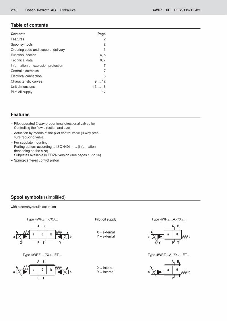
Spool symbols (simplified)
with electrohydraulic actuation
Type 4WRZ…-7X./… Pilot oil supply Type 4WRZ…A.-7X./…
for spool symbol E1 and W8:P → A: qV max B → T: qV/2P → B: qV/2 A → T: qV maxfor spool symbol E3 and W9:P → A: qV max B → T: lockedP → B: qV/2 A → T: qV max(Differential circuit, piston top at port A)Important: In spool position "0", spools W6-, W8-, W9-, W6A have a connection from A → T and B → T with approx. 2% of the relevant nominal cross-section.
M = 1) NBR sealsV = FKM seals
Important: Observe compatibility
of seals with hydraulic fluid used!
D3 = with pressure reducing valve (preset)
Pilot oil supply and return
No code = Pilot oil supply external,Pilot oil return external
E = Pilot oil supply internal, Pilot oil return externalET = Pilot oil supply internal, Pilot oil return internalT = Pilot oil supply external, Pilot oil return internal
For details, see page 17. Surface protection
J = Seawater-resistant, galvanized and passivated olive-green
XE = Explosion protection "e",for details see information on
the explosion protection, Page 7 Supply voltage of the control electronics
G24 = 24 V direct voltage6E = Proportional solenoid
7X = Component series 70 to 79 (70 to 79: Identical installation and connection dimensions)
1) Suitable for mineral oils (HL, HLP) according to DIN 51524
Included in the delivery:Valve operating instructions with declaration of conformity in part III
4/18 Bosch Rexroth AG Hydraulics 4WRZ…XE RE 29115-XE-B2
Function, section
Type 3DREP 6..2X/..XE..
Pilot control valve type 3DREP 6…The pilot control valve is a 3-way pressure reducing valve that is actuated by a proportional solenoid. It converts an electrical input signal into a proportional pressure output signal and is used for all valves of the type 4WRZ ...The proportional solenoids are adjustable wet-pin DC sole-noids. The solenoids are actuated by external control elec-tronics.Set-up:The valve basically consists of:– Housing (1) with connection surface– Control piston (2) with pressure measuring spool (3 and 4)– Solenoids (5 and 6) with central thread
Functional description:The pressure in A or B is set by means of the proportional so-lenoids. The amount of the pressure depends on the current.With de-energized solenoids (5, 6), the control piston (2) is held in the central position by means of the pressure springs (8). Ports A and B are connected with T so that the hydraulic fluid can flow off to the tank without obstructions.
By actuating a proportional magnet, e. g. solenoid "b" (5), the pressure measuring spool and the control piston with it (2) are moved to the left. This opens the connection from P to A and B to T via orifice-type cross-sections with progressive flow characteristic. The pressure that builds up in channel B acts with the surface of the pressure measuring spool (3) on the control piston and against the solenoid force. The pres-sure measuring spool (3) is supported by the solenoid "a". If the pressure exceeds the value set at solenoid "b", the control piston (2) is pushed back against the solenoid force and con-nects A with T until the set pressure is achieved again. The pressure is proportional to the solenoid current.After shut-down of the solenoid, the control piston (2) is re-turned into the central position by the compression springs (8).Important:Regarding valves of the version 3DREP 6 C, only one solenoid may be actuated at a time.
Valve with two spool positions(Type 3DREP 6…A…)The function of this valve design basically corresponds to the valve with 3 spool positions. This 2 spool position valve is, however, only equipped with solenoid "b" (5). Instead of the 2nd proportional solenoid, there is a plug screw (7).
Important:The tank line must not be allowed to run empty. With corre-sponding installation conditions, a preload valve (pre-charging pressure approx. 2 bar) must be installed.
Function, sectionPilot operated proportional directional valvesType 4WRZ…-7X/..XEValves of the type 4WRZ... are pilot operated 4-way direc-tional valves that are actuated by means of proportional sole-noids. You control the flow direction and size.
Set-up:The valve basically consists of:– Pilot control valve (9) with proportional solenoids (5 and 6)– Main valve (10) with main spool (11) and centering
spring (12)
Functional description:– With de-energized solenoids (5 and 6), the main spool
(11) is held in the central position by means of a centering spring (12).
– Actuation of the main spool (11) using the pilot control valve (9) – the main spool is moved proportionally – e.g. Actuation solenoid "b" (6)→ Movement of the control piston (2) to the right, via the pilot control valve (9), pilot oil reaches the pressure chamber (13) and moves the main spool (11) proportionally to the electrical input signal to the left→ Connection of P → A and B → T via orifice-type cross-sections with progressive flow characteristics
– Pilot oil supply to the pilot control valve internally via port P or externally via port X
– Shut-down of the solenoid (6) → Control piston (2) and main spool (11) are moved back
into the central position.– Flow depending on the spool position from P → A and
B → T or P → B and A → T.
Type 4WRZ…-7X/..XE..
6/18 Bosch Rexroth AG Hydraulics 4WRZ…XE RE 29115-XE-B2
Technical data
GeneralInstallation position Any, preferably horizontal Storage temperature range °C –20 … +70Ambient temperature range °C –20 … +70 Weight, maximum Size 10 kg 10
Size 16 kg 16Size 25 kg 21Size 32 kg 45
Surface protection Galvanized and passivated olive-green
HydraulicSize Size 10 16 25 32Operating pressure range
Pilot control valve Pilot oil supply externalor internal bar 30 … 315 30 … 350 30 … 350 30 … 350
Main valve bar up to 315 up to 350 up to 350 up to 350Return flow pressure
Port T(Pilot oil return external) bar up to 315 up to 250 up to 250 up to 150
Port T(Pilot oil return internal) bar up to 30 up to 30 up to 30 up to 30
Port Y bar up to 30 up to 30 up to 30 up to 30Pilot volumefor switching process 0 → 100% cm3 1.7 4.6 10 26.5
Pilot flow at port X and Ywith stepped input signal 0 → 100% l/min 3.5 5.5 7 15.9
Flow of the main valve l/min up to 170 up to 460 up to 870 up to 1600Hydraulic fluid Mineral oil (HL, HLP) according to DIN 51524,
additional hydraulic fluids upon request!Ignition temperature > 180 °C
Hydraulic fluid temperature range °C –30 ... +80 (NBR seals)°C –15 ... +80 (FKM seals)
Viscosity range mm2/s 20 ... 380 (preferably 30 ... 46)Max. permissible degree of contamination of the hydraulic fluid
Class 17/15/12 1)Cleanliness class accord-ing to ISO 4406 (c)
Pilot control valveMain valve Class 18/16/13 1)
Hysteresis % ≤ 6
1) The cleanliness classes specified for the components must be adhered to in hydraulic systems. Effective filtration pre-vents faults and at the same time increases the service life of the components. For the selection of the filters see www.boschrexroth.com/filter.
ElectricVoltage type Direct voltage or pulse width modulated
signal 100 … 500 Hz Type of signal AnalogMaximum current per solenoid A 1.03Solenoid coil resistance
Cold value at 20 °C Ω 8.7Maximum hot value Ω 12.9
Duty cycle % 100Coil temperature °C up to 125Electrical connection
Threaded connection M20 x 1.5Line diameter mm 9 … 11 Protection class according to EN 60529:1991+A1:2000 IP 66 in mounted or installed state
Seal material FKM
Technical data
Range of application as per directive 94/9/EC II 2GType of protection valve according to EN 13463-1:2007 / EN 13463-5:2003 c T4 X
Type of protection valve solenoid according to EN 60079-7:2007 / EN 60079-18:2005 EEx em IIT4 1)
Type examination certificate Solenoid KEMA 02 ATEX 2240Special operating conditions for a safe application Marker X: In all operating states, maximally one
solenoid may be operated at a time.Ambient temperature range °C –20 … +70
1) Surface temperature > 50 °C, provide contact protection2) Important: The power supply of the proportional solenoids must
comply with Directive 94/9/EC (equipment and protective systems intended for use in potentially explosive areas).A monitoring circuit is to be provided for the monitoring of the solenoid current. We recommend operating the valves with the assemblies described herein.
Information on explosion protection
Amplifier module for the actuation of explosion-proof pro-portional directional valves 4WRA...XE, 3DREP 6...XE and 4WRZ...XE
VT-MSPA2-200-1X/V0/0 according to data sheet 30228-200
Module for monitoring and limiting the solenoid currents with proportional valves VT-MUXA2-2-1X/V0/1A according to data sheet 30290
Control electronics 2)
8/18 Bosch Rexroth AG Hydraulics 4WRZ…XE RE 29115-XE-B2
Electrical connectionThe type-tested valve solenoid of the valve is equipped with a terminal box and a type-tested cable gland.The connection is insensitive to polarity.
Important:If the valve is not operated with the module VT-MUXA2-2-1X/V0/1A (see page 7), a fuse appropriate for the valve solenoid‘s rated current (max. 3 x Irated according to DIN 41571 and/or IEC 60127) or a protective motor switch with short-circuit and thermal instantaneous tripping must be connected to each valve solenoid as short-circuit protection. The cut-off capacity of this fuse must match or exceed the short-circuit current of the supply source. This fuse or motor protection switch may only be fitted outside the explosive area or must be of an explosion-proof design.
3) Recommended pre-fusecharacteristics medium time-lag according to DIN 41571, 1.25 A.
Suppressor diode47 V, 1.5 kW
Properties of the terminals and mounting elementsItem Function Connectable line cross-section Tightening torque
Characteristic curves size 10(measured with spools "E, W6-, EA, W6A" as well as HLP46, ϑoil = 40 °C ± 5 °C)
1 ∆p = 10 bar constant2 ∆p = 20 bar constant3 ∆p = 30 bar constant4 ∆p = 50 bar constant5 ∆p = 100 bar constant
1 ∆p = 10 bar constant2 ∆p = 20 bar constant3 ∆p = 30 bar constant4 ∆p = 50 bar constant5 ∆p = 100 bar constant
1 ∆p = 10 bar constant2 ∆p = 20 bar constant3 ∆p = 30 bar constant4 ∆p = 50 bar constant5 ∆p = 100 bar constant
Ordering code 25: 26 l/min at a valve pressure differential of 10 bar
Ordering code 85: 87 l/min at a valve pressure differential of 10 bar
Ordering code 50: 49 l/min at a valve pressure differential of 10 bar
∆p = valve pressure differential according to DIN 24311 (inlet pressure pP minus load pressure pL minus return flow pressure pT)Transition function with stepped electric input signals
1 Main valve2 Pilot control valve3 Proportional solenoid "a"4 Proportional solenoid "b"5 Terminal box6 Plug screw for valves with one solenoid7 Name plate for pilot control valve8 Name plate for main valve9 Pressure reducing valve (always available)
10 Identical seal rings for ports P, A, B, T and T111 Identical seal rings for X and Y12 Machined valve mounting face, porting pattern
according to ISO 4401-05-05-0-05 (X, Y as required, T1 is available at the valve and can optionally be provided) Deviating from the standard:
– Locating pin not available
! !
!!
Rzmax 4
0,01/100
Required surface qualityof the valve mounting face
Subplates G 534/01 FE/ZN (G3/4) without ports X and YG 535/01 FE/ZN (G3/4) with ports X and YG 536/01 FE/ZN (G1) with ports X and Ywith dimensions as in the data sheet 45054 must be ordered separately.
Valve mounting screwsFor reasons of stability, exclusively use the following valve mounting screws:4 hexagon socket head cap screws ISO 4762-M6x45-10.9-flZn-240h-L(tot. friction coefficient: 0.09-0.14 according to VDA 235-101) (must be ordered separately)Important:Subplates are no components in the sense of directive 94/9/EC and can be used after the manufacturer of the overall system has assessed the risk of ignition.The G...FE/ZN versions are free from aluminum and/or magnesium and galvanized.
14/18 Bosch Rexroth AG Hydraulics 4WRZ…XE RE 29115-XE-B2
Unit dimensions size 16 (dimensions in mm)
1 Main valve2 Pilot control valve3 Proportional solenoid "a"4 Proportional solenoid "b"5 Terminal box6 Plug screw for valves with one solenoid7 Name plate for pilot control valve8 Name plate for main valve9 Pressure reducing valve (always available)
10 Identical seal rings for ports P, A, B and T11 Identical seal rings for X and Y12 Machined valve mounting face, porting pattern
according to ISO 4401-07-07-0-05 (X, Y as required) Deviating from the standard:
– Ports P, A, B and T with Ø 20 mm13 Locating pin
"
""
!
!
!!
!
!#
#
Rzmax 4
0,01/100
Required surface qualityof the valve mounting face
Subplates G 172/01 FE/ZN (G3/4) G 172/02 FE/ZN (M27 x 2)G 174/01 FE/ZN (G1) G 174/02 FE/ZN (M33 x 2) G 174/08 FE/ZN (flange)with dimensions as in the data sheet 45056 must be ordered separately.
Valve mounting screwsFor reasons of stability, exclusively use the following valve mounting screws:2 hexagon socket head cap screws ISO 4762-M6x60-10.9-flZn-240h-L(tot. friction coefficient: 0.09-0.14 according to VDA 235-101) (must be ordered separately)4 hexagon socket head cap screws ISO 4762-M10x60-10.9-flZn-240h-L(tot. friction coefficient: 0.09-0.14 according to VDA 235-101) (must be ordered separately)Important:Subplates are no components in the sense of directive 94/9/EC and can be used after the manufacturer of the overall system has assessed the risk of ignition.The G...FE/ZN versions are free from aluminum and/or magnesium and galvanized.
1 Main valve2 Pilot control valve3 Proportional solenoid "a"4 Proportional solenoid "b"5 Terminal box6 Plug screw for valves with one solenoid7 Name plate for pilot control valve8 Name plate for main valve9 Pressure reducing valve (always available)
10 Identical seal rings for ports P, A, B and T11 Identical seal rings for X and Y12 Machined valve mounting face, porting pattern
according to ISO 4401-08-08-0-05 (X, Y as required)13 Locating pin
!
!
!!
!
!#
#
Rzmax 4
0,01/100
Required surface quality of the valve mounting face
Subplates G 151/01 FE/ZN (G1) G 154/01 FE/ZN (G1 1/4) G 154/08 FE/ZN (flange)G 156/01 FE/ZN (G1 1/2) with dimensions as in the data sheet 45058 must be ordered separately.
Valve mounting screwsFor reasons of stability, exclusively use the following valve mounting screws:6 hexagon socket head cap screws ISO 4762-M12x60-10.9-flZn-240h-L(tot. friction coefficient: 0.09-0.14 according to VDA 235-101) (must be ordered separately)Important:Subplates are no components in the sense of directive 94/9/EC and can be used after the manufacturer of the overall sys-tem has assessed the risk of ignition.The G...FE/ZN versions are free from aluminum and/or mag-nesium and galvanized.
16/18 Bosch Rexroth AG Hydraulics 4WRZ…XE RE 29115-XE-B2
Unit dimensions size 32 (dimensions in mm)
1 Main valve2 Pilot control valve3 Proportional solenoid "a"4 Proportional solenoid "b"5 Terminal box6 Plug screw for valves with one solenoid7 Name plate for pilot control valve8 Name plate for main valve9 Pressure reducing valve (always available)
10 Identical seal rings for ports P, A, B and T11 Identical seal rings for X and Y12 Machined valve mounting face, porting pattern
according to ISO 4401-10-09-0-05 (X, Y as required) Deviating from the standard:
– Ports P, A, B and T with Ø 38 mm13 Locating pin
"
""
"
! !
!!
!
!#
#
Rzmax 4
0,01/100
Required surface quality of the valve mounting face
Subplates G 157/01 FE/ZN (G1 1/2) G 157/02 FE/ZN (M48 x 2) G 158/10 FE/ZN (flange) with dimensions as in the data sheet 45060 must be ordered separately.
Valve mounting screwsFor reasons of stability, exclusively use the following valve mounting screws:6 hexagon socket head cap screws ISO 4762-M20x80-10.9-flZn-240h-L(tot. friction coefficient: 0.09-0.14 according to VDA 235-101) (must be ordered separately)Important:Subplates are no components in the sense of directive 94/9/EC and can be used after the manufacturer of the overall system has assessed the risk of ignition.The G...FE/ZN versions are free from aluminum and/or magnesium and galvanized.
Type 4WRZ…-…/… Pilot oil supply externalPilot oil return externalWith this version, the pilot oil is supplied from a separate pilot circuit (external).The pilot oil return is not directed into the T channel of the main valve, but is separately directed to the tank via port Y (external).
Type 4WRZ…-…/…E…Pilot oil supply internalPilot oil return externalWith this version, the pilot oil is supplied by the P channel of the main valve (internal).The pilot oil return is not directed into the T channel of the main valve, but is separately directed to the tank via port Y (external).In the subplate, port X is to be closed.
Type 4WRZ…-…/…ET…Pilot oil supply internalPilot oil return internalWith this version, the pilot oil is supplied by the P channel of the main valve (internal).The pilot oil is directly returned to channel T of the main valve (internal).In the subplate, ports X and Y are closed.
Type 4WRZ…-…/…T…Pilot oil supply externalPilot oil return internalWith this version, the pilot oil is supplied from a separate pilot circuit (external).The pilot oil is directly returned to channel T of the main valve (internal).In the subplate, port Y is to be closed.
Pilot oil supply
18/18 Bosch Rexroth AG Hydraulics 4WRZ…XE RE 29115-XE-B2