48
OWNER’S MANUAL 424@$ 3D0023100A

OWNER’S MANUAL
424@$
3D0023100A

2
Safety Instructions 3Introduction 4The Recording System 5
The three steps to multitrack 5Understanding the Mixer 6-7
Signal flow in the 424 MKIII mixer 6Tape cue monitor system 7
Multitrack Cassette Recorder 8Track Format and Tape Recommendations 9-10PORTASTUDIO 424 MKIII Brief Guide 11-14Step-By-Step Operations Guide 15-24
Let's try the 424 MKIII mixer 15How to record on track 1 16Track 1 playback through TAPE CUE 18How to make an overdub on track 2 19How to record tracks 3 and 4 20How to record many sources onto a
single track 20How to record a mix onto two tracks
simultaneously 21Recording on more than two tracks
simultaneously : DIRECT 22How to mix down 23
Using Memory Location Points 25-26Loading MEMO points 25Locating the tape 26
Repeat Play 27PUNCH-IN or INSERT Recording 28-32
Preliminary 28Rehearsal and auto in/out procedures 29Manual punch-in 31
Bouncing Tracks (Ping-Pong) 33-34Ping-pong procedure 33
Using Effects with the PORTASTUDIO 424 MKIII 35-36
Setting effect send levels 35Setting the output level of effect devices 35Setting the mix/balance control
on effect devices 35How to connect your effects devices 36
Syncing MIDI-Tape—Using the TASCAM MTS-30 37
Troubleshooting 38Features and Controls 39-45
424 MKIII MixerInput section 40Stereo input section 41Monitor section 41Master section 41Output section 41
424 MKIII RecorderCassette loading and dbx system 42Transport controls 43Track controls 44Displays 44Autolocators 44
Optional Accessories 47Care and Maintenance 48-49How the dbx Works 49Specifications 50-52Block Diagram 53-54Level Diagram 55
Table Of Contents
"© Copyright 1998, TEAC Corporation"All rights reserved under international and Pan American copyright conventions.This book may not be reproduced in whole or in part, by mimeograph or any other means,without permission.
"The following marking is located on the bottom of the unit."
This appliance has a serial number locatedon the rear panel. Please record the modelnumber and serial number and retain themfor your records.Model numberSerial number
WARNING: TO PRIVENT FIRE OR SHOCKHAZARD, DO NOT EXPOSE THIS APPLIANCE TO RAIN OR MOISTURE.
CAUTION: TO REDUCE THE RISK OF ELECTRIC SHOCK, DO NOT REMOVE COVER (OR BACK). NO USER-SERVICEABLE PARTSINSIDE. REFER SERVICING TO QUALIFIED SERVICE PERSONNEL.
The lightning flash with arrowhead symbol, within equilateral triangle, is intended to alertthe user to the presence of uninsulated "dangerous voltage" within the product's enclosurethat may be of sufficient magnitude to constitute a risk of electric shock to person.
The exclamation point within an equilateral triangle is intended to alert the user to thepresence of important operating and maintenance (servicing) instructions in theliterature accompanying the appliance.
CAUTIONRISK OF ELECTRIC SHOCK
DO NOT OPEN

3
Safety Instructions
CAUTION:• Read all of these Instructions.• Save these Instructions for later use.• Follow all Warnings and Instructions marked on the
audio equipment.
1) Read instructions — All the safety and operating instructionsshould be read before the product is operated.2) Retain instructions — The safety and operating instructions shouldbe retained for future reference.3) Heed Warnings — All warnings on the product and in the operatinginstructions should be adhered to.4) Follow instructions — All operating and use instructions shoud befollowed.5) Cleaning — Unplug this product from the wall outlet before cleaning.Do not use liquid cleaners or aerosol cleaners. Use a damp cloth forcleaning.6) Attachments — Do not use attachments not recommended by theproduct manufacturer as they may cause hazards.7) Water and Moisture — Do not use this product near water _ forexample, near a bath tub, wash bowl, kitchen sink, or laundry tub; in a wetbasement; or near a swimming pool; and the like.8) Accessories — Do not place this product on an unstable cart, stand,tripod, bracket, or table. The product may fall, causing serious injury to achild or adult, and serious damage to the product. Use only with a cart,stand, tripod, bracket, or table recommended by the manufacturer, or soldwith the product. Any mounting of the product should follow themanufacturer’s instructions, and should use a mounting accessoryrecommended by the manufacturer.9) A product and cart combination should be moved with care. Quickstops, excessive force, and uneven surfaces may cause the product and cartcombination to overturn.
10) Ventilation — Slots and openings in the cabinet are provided forventilation and to ensure reliable operation of the product and to protect itfrom overheating, and these openings must not be blocked or covered. Theopenings should never be blocked by placing the product on a bed, sofa,rug, or other similar surface. This product should not be placed in a built-ininstallation such as a bookcase or rack unless proper ventilation is providedor the manufacturer’s instructions have been adhered to.11) Power Sources — This product should be operated only from thetype of power source indicated on the marking label. If you are not sure ofthe type of power supply to your home, consult your product dealer or localpower company. For products intended to operate from battery power, orother sources, refer to the operating instructions.12) Grounding or Polarization — This procuct may be equipped witha polarized alternating-current line plug (a plug having one blade widerthan the other). This plug will fit into the power outlet only one way. Thisis a safety feature. If you are unable to insert the plug fully into the outlet,try reversing the plug. If the plug should still fail to fit, contact yourelectrician to replace your obsolete outlet. Do not defeat the safety purposeof the polarized plug.13) Power-Cord Protection — Power-supply cords shoud be routed sothat they are not likely to be walked on or pinched by items placed upon oragainst them, paying particular attention to cords at plugs, conveniencereceptacles, and the point where they exit from the product.14) Outdoor Antenna Grounding — If an outside antenna or cablesystem is connected to the product, be sure the antenna or cable system isgrounded so as to provide some protection against voltage surges and built-up static charges. Article 810 of the National Electrical Code, ANSI/NFPA70, provides information with regard to proper grounding of the mast andsupporting structure, grounding of the lead-in wire to an antenna dischargeunit, size of grounding conductors, location of antenna-discharge unit,connection to grounding electrodes, and requirements for the groundingelectrode.
"Note to CATV system installer:This reminder is provided to call the CATV system installer’s attention toSection 820-40 of the NEC which provides guidelines for proper groundingand, in particular, specifies that the cable ground shall be connected to thegrounding system of the building, as close to the point of cable entry aspractical.
15) Lightning — For added protection for this product during a lightningstorm, or when it is left unattended and unused for long periods of time,unplug it from the wall outlet and disconnect the antenna or cable system.This will prevent damage to the product due to lightning and power-linesurges.16) Power Lines — An outside antenna system should not be located inthe vicinity of overhead power lines or other electric light or power circuits,or where it can fall into such power lines or circuits. When installing anoutside antenna system, extreme care should be taken to keep fromtouching such power lines or circuits as contact with them might be fatal.17) Overloading — Do not overload wall outlets, extension cords, orintegral convenience receptacles as this can result in risk of fire or electricshock.18) Object and Liquid Entry — Never push objects of any kind intothis product through openings as they may touch dangerous voltage pointsor short-out parts that could result in a fire or electric shock. Never spillliquid of any kind on the product.19) Servicing — Do not attempt to service this product yourself asopening or removing covers may expose you to dangerous voltage or otherhazards. Refer all servicing to qualified service personnel.20) Damage Requiring Service — Unplug this product from the walloutlet and refer servicing to qualified service personnel under the followingconditions:a) when the power-supply cord or plug is damaged.b) if liquid has been spilled, or objects have fallen into the product.c) if the product has been exposed to rain or water.d) if the product does not operate normally by following the operatinginstructions. Adjust only those controls that are covered by the operatinginstructions as an improper adjustment of other controls may result indamage and will often require extensive work by a qualified technician torestore the product to its normal operation.e) if the product has been dropped or damaged in any way.f ) when the product exhibits a distinct change in performance _ thisindicates a need for service.21) Replacement Parts — When replacement parts are required, besure the service technician has used replacement parts specified by themanufacturer or have the same characteristics as the original part.Unauthorized substitutions may result in fire, electric shock, or otherhazards.22) Safety Check — Upon completion of any service or repairs to thisproduct, ask the service technician to perform safety checks to determinethat the product is in proper operating condition.23) Wall or Ceiling Mouting — The product shoud be mounted to awall or ceiling only as recommended by the manufacturer.24) Heat — The product should be situated away from heat sources suchas radiators, heat registers, stoves, or other products (including amplifiers)that produce heat.
ANTENNALEAD INWIRE
ANTENNADISCHARGE UNIT(NEC SECTION 810-20)
GROUNDING CONDUCTORS(NEC SECTION 810-21)
GROUND CLAMPS
POWER SERVICE GROUNDINGELECTRODE SYSTEM(NEC ART 250. PART H)
NEC - NATIONAL ELECTRICAL CODE
ELECTRICSERVICEEQUIPMENT
Example of Antenna Grounding as perNational Electrical Code, ANSI/NFPA 70
GROUNDCLAMP
Using this manual : To get the most out of your424 MKIII, please take the time to read throughthis manual. Some time spent now will keep youfrom overlooking some of the features that makethe 424 MKIII a more creative tool. You maydiscover some new tricks you haven't triedbefore.
Use of capital letters : In general, we use all uppercase type to designate a particular switch,control, jack name or label (like PAN). Transportmodes and some features are described with anupper case first letter (like Record mode).
The PORTASTUDIO 424 MKIII is...
The PORTASTUDIO 424 MKIII is a 4-track"Multitrack Master" cassette tape recorder and afull-function mixer with 8 inputs/stereo outputscombined into a single workstation.
Its high audio quality and creative flexibilityreflect the experience and innovation that haveallowed TASCAM to earn its reputation inprofessional audio production fields, and its user-friendly design makes the 424 MKIII suitable foranyone, from expert to novice.
NOTE FOR U.K. CUSTOMERS
DO NOT cut off the mains plug from thisequipment. If the plug fitted is not suitable for thepower points in your home or the cable is tooshort to reach a power point, then obtain anappropriate safety approved extension lead orconsult your dealer.
If nonetheless the mains plug is cut off, removethe fuse and dispose of the plug immediately, toavoid a possible shock hazard by inadvertentconnection to the mains supply.
If this product is not provided with a mains plug,or one has to be fitted, then follow theinstructions given below:
IMPORTANT. DO NOT make any connection tothe larger terminal which is marked with the letterE or by the safety earth symbol ç or colouredGREEN or GREEN-and-YELLOW.
The wires in the mains lead on this product arecoloured in accordance with the following code:
BLUE: NEUTRALBROWN: LIVE
Introduction
CAUTION : TO PREVENT ELECTRIC SHOCK,MATCH WIDE BLADE OF PLUG TO WIDESLOT, FULLY INSERT
ATTENTION : POUR ÉVITER LES CHOCSÉLECTRIQUES, INTRODUIRE LA LAME LAPLUS LARGE DE LA FICHE DANS LA BORNECORRESPONDANTE DE LA PRISE ETPOUSSER JUSQU' AU FOND.
About the weld line
There is a patterned stripe-like effect on thebottom surface of the 424 unit. This effect iscalled a "weld line" and is a natural result ofthe resin molding process employed in themanufacture of the 424 unit. It is not a crackor scratch, and will cause no problems withthe operation of the 424 unit.
As these colours may not correspond with thecoloured markings identifying the terminals inyour plug proceed as follows:
The wire which is coloured BLUE must beconnected to the terminal which is marked withthe letter N or coloured BLACK.
The wire which is coloured BROWN must beconnected to the terminal which is marked withthe letter L or coloured RED.
When replacing the fuse only a correctly ratedapproved type should be used and be sure to re-fit the fuse cover.
IF IN DOUBT — CONSULT A COMPETENTELECTRICIAN.
4

5
The PORTASTUDIO 424 MKIII is a complete audioproduction facility in a single box. It is dividedinto two major sections: a full-function mixer andan 4-channel, multitrack cassette recorder.
To complete the recording system, you'lladditionally need these: Input devices(microphones, instruments), Output devices(headphones), 2 track recorder, Effectsprocessors, etc.
The Recording System
The Three Steps to Multitrack
In TRACKING and Overdubbing, the mixer inputsare usually microphones or instruments, going todifferent tracks of the recorder.
In OVERDUBBING, the MONITOR section andTAPE CUE of the mixer must be used to listen toprevious tracks while you record new ones, sothere is a two-way flow through the console.
In MIXDOWN, signal comes from the multitrackand is sent to an external 2-track recorder.

6
jacks. This is the most important signal route inthe mixer and is called "Main Mix".
The illustration below shows how input signalspass through the 424 MKIII Mixer section. Afterthe MASTER fader they go to the L/R LINE OUT
Signal Flow in the 424 MKIII Mixer
Understanding the Mixer

7
Tape Cue Monitor System
The TAPE CUE mix and MONITOR switches arealso crucial for successful multitrack recording,because they control what you hear in theheadpnones. This CUE mix is totally independentfrom the Main Mix going to tape. If you don't usethe CUE mix, you run the risk of accidentally"bouncing tracks" every time you record newmaterial.
The 4 TAPE CUE controls act like a separate 4x1mixer, dedicated solely to enabling you to hearplayback from the multitrack recorder in yourheadphones. The settings of these controls don’taffect the mix going to tape. When theEFFECT/CUE switch is set to the center position(EFFECT 2/CUE), the EFFECT 2/TAPE CUE switchis set to TAPE CUE, the TAPE CUE of the tracksyou want to hear are turned clockwise, and theMONITOR LEVEL is turned up, you can hear thetape playback in the headphones and MONITORoutputs. You can adjust the monitor level of eachtrack by adjusting its TAPE CUE control. Thechannels of the Main Mix remain free to handleexternal inputs for recording.
If you can hear tape playback in your headphoneswhen TAPE CUE is off (in the left position), itmeans you're hearing tape through the Main Mix.This is correct for mixdown and bouncing tracks,but during overdubbing it can cause previoustracks to be mixed together with new tracks,instead of each part remaining separate. Use theTAPE CUE to avoid this.
The MONITOR SELECT LINE OUT switch affectswhether you will hear the off-tape signal (OFF), orthe LINE OUT signals in MONO or stereo (L-R).When you are recording, you should set thisswitch to OFF, the EFFECT/CUE switch to EFFECT2/CUE, and the EFFECT 2/TAPE CUE switch toTAPE CUE.

8
∑ A three-point autolocator (MEMO/LOC 1 and 2and RTZ) lets the tape STOP at, or PLAY frompreset points.
∑ REPEAT allows a section to be played overand over between the MEMO 1 and MEMO 2points.
∑ REHEARSAL programs the 424 MKIII to repeata punch-in/out sequence as many times asyou wish, and AUTO PUNCH actually executesit on tape exactly as you "previewed" inREHEARSAL.
∑ Two tape speeds offer HIGH for greaterfidelity, and NORMAL for compatibility withstandard cassette tapes.
∑ The tape speed can be increased or decreasedwith the PITCH CONTROL dial in bothplayback and record, to match pitch or forspecial effects.
The 424 MKIII records on readily availablestandard (Philips) Compact Cassette tape, highbias Type II. The recorder has 4 tracks while themixer has a stereo output; however, using theDIRECT feature you can record on any or all ofthe 4 tracks at one time. For more details, see"Recording on More Than Two TracksSimultaneously", page 22.
The 424 MKIII's dbx Noise Reduction virtuallyeliminates unwanted tape noise. A special SYNCfeature tuns off the dbx on track 4 separately,making it possible to record and play back theMIDI sync tones or SMPTE/EBU time codewithout being affected by the dbx encode/decode.This ensures that the sync tones/code arerecorded and played back without unnecessaryprocessing. With proper operating techniques, itis not necessary to leave a guard band betweenmusic and sync tone tracks because of the lowcrosstalk of the TASCAM heads.
The transport controls of the 424 MKIII are micro-processor operated, allowing highly reliablefunctions that make the unit easier to use:
Multitrack Cassette Recorder

9
Tape Speed and Track FormatThe Portastudio 424 MKIII uses a HIGH speed of9.5 cm/sec. (3-3/4 inches per second) which is twotimes (2X) the normal speed of a standard audiocassette. Its NORMAL speed is 4.8 cm/sec (1-7/8i.p.s.), the same as that used by conventionalrecorders.
It also employs a discrete 4-channel format headdeveloped especially by TEAC for TASCAMmultitrack cassette recorders. Here is acomparison of various cassette formats:
Track Format and Tape Recommendations
Playing back standard (stereo) prerecordedtapes: Tapes recorded on stereo cassetterecorders can play back properly on the 424 MKIIIif you set the track playback, tape speed, andnoise reduction type correctly. Tracks 1 and 2roughly follow the standard "stereo" format, buttracks 3 and 4 use the "Side B" (reverse side)tracks. So you must turn off Track 3-4 playback toavoid hearing the flip side playing backwards. Ifthe cassette was recorded with Dolby B typenoise reduction, the DBX NR switch should be setto OFF.
For the same reasons, tapes recorded on thePortastudio 424 MKIII will not play back properlyon stereo cassette recorders. Material recordedon the 424 MKIII must be mixed down to stereofor final distribution.
The 424 MKIII needs the entire width of the tapeto record its four tracks, eliminating the option ofrecording on both sides (actually, it's bothdirections). Therefore, you should decide which
side (side "A" or side "B") you want to use anduse that side exclusively. It's a good idea to getinto habit of consistently using the same side onall multitrack tapes.
Tape TypeThe Portastudio 424 MKIII is internally adjustedfor HIGH BIAS Type II tape. This means that forbest results, you should only use tapes of thistype. TDK SA, Maxell XL-II or equivalentformulations are recommended. We stronglysuggest that you select one good quality brandand use it exclusively. The time you spendcreating your multitrack master is much morevaluable than the money you save by buyinginferior tape. The cassette shell essentiallybecomes a part of the 424 MKIII's transport. Poorquality shells can cause wrinkles, snarls andshredding of the edges of the tape with use. Evensmall scratches on the tape oxide can cause"dropouts" (temporary loss of signal) on one ormore tracks. High quality tapes are less likely tocause problems in the long run.
10
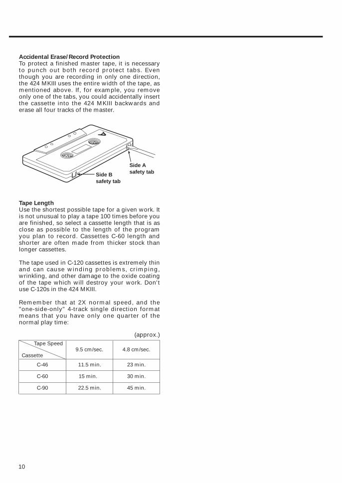
Accidental Erase/Record ProtectionTo protect a finished master tape, it is necessaryto punch out both record protect tabs. Eventhough you are recording in only one direction,the 424 MKIII uses the entire width of the tape, asmentioned above. If, for example, you removeonly one of the tabs, you could accidentally insertthe cassette into the 424 MKIII backwards anderase all four tracks of the master.
Tape LengthUse the shortest possible tape for a given work. Itis not unusual to play a tape 100 times before youare finished, so select a cassette length that is asclose as possible to the length of the programyou plan to record. Cassettes C-60 length andshorter are often made from thicker stock thanlonger cassettes.
The tape used in C-120 cassettes is extremely thinand can cause winding problems, crimping,wrinkling, and other damage to the oxide coatingof the tape which will destroy your work. Don'tuse C-120s in the 424 MKIII.
Remember that at 2X normal speed, and the"one-side-only" 4-track single direction formatmeans that you have only one quarter of thenormal play time:
Tape Speed
Cassette9.5 cm/sec. 4.8 cm/sec.
C-46 11.5 min. 23 min.
C-60 15 min. 30 min.
C-90 22.5 min. 45 min.
(approx.)
Side Asafety tabSide B
safety tab

Ch 7-8
STEREO INPUT: Connect any stereoline-level signal (such an effectreturn or electronic instrument)here. Alternatively, you canconnect two mono line-levelsignals.
MONO feature: If only one monosignal is to be connected,connect it to the L jack, andleave the R jack unconnected.The signal is automatically takento both the 7 and 8 channels.
LEVEL: Controls the volume of bothof the inputs simultaneously.The signal is sent to thedestination selected by theASSIGN switch.
ASSIGN: This sends the signal(s) atthe STEREO INPUT to the stereomix for recording (L-R) or to themonitor mix (MON), or turns thesignals OFF (center).
LINE OUT switch: Controls whetherthe LINE OUT stereo mix will beoutput to the monitor mix, instereo (L-R), in mono (MONO) ornot at all (OFF).
EFFECT/CUE switch: Controlswhether the signals sent toEFFECT 1 or EFFECT 2/CUE orneither (OFF) will be output tothe monitor mix, or you mayselect neither of these formonitoring (OFF).
LEVEL: Controls the level of themonitor mix feeding theMONITOR OUT jacks andheadphones.
EFFECT 2/TAPE CUE switch: Thisalters the function of the fourlevel controls immediatelyabove the pan controls ofchannels 1 through 4.
MASTER fader: This sets the totaloutput level of the stereo mix.
Ch.1-4
MIC/LINE INPUTS: These are the input jacks forthe mixer channels. Primarily, the 3-contact,XLR-type connectors are for connection tobalanced microphones, and the 1/4" jacksare for line-level, unbalanced signal sources(such as electronic instruments). But youcan also connect lower-level signals (downto –50 dBV) to these 1/4" jacks and use theTRIM control to amplify them.
TRIM : Sets how much preamplification will beadded to the MIC/LINE IN jack. Turn to theright if the signal needs amplification, to theleft if the signal is so loud it is distorting themixer electronics.
INPUT : Detemines where the channel signalcomes from.MIC/LINE (left) brings the mic/line inputinto the channel.OFF (center) shuts off the channel.TAPE (right) makes tape play back thechannel source.
EQ HIGH : Cuts or boosts treble frequencies.Shelving point is at 10 kHz.
EQ MID sweep : The upper control sets thefrequency range, centered from 250 Hz to 5 kHz. The lower control cuts or boosts thisfrequency range.
EQ LOW : Cuts or boosts bass frequencies.Shelving point is at 100 Hz.
EFFECT 1 and 2 : These control how much signalwill go to the corresponding EFFECT sendjacks. They get their signal from a point justafter the channel fader.
TAPE CUE : The EFFECT 2 controls can beswitched to act as the TAPE CUE levelcontrols (by means of the correspondinglylabeled switch) and adjust the playbacklevel for the musicians in the studio.
PAN : Sets the pan position (left-right balance) ofthe channel. Note that the Left Mix can berecorded on tracks 1 and 3, and the RightMix onto tracks 2 and 4.
Channel fader : Sets the volume of the channelfeeding the MASTER fader.
1211
Input Selection and Adjustment
NOTE
DO NOT use both the XLR and 1/4" jacksin the same channel at one time.Disconnect one when the other is used.
PORTASTUDIO 424 MKIII Brief GuideFor detailed information on each feature, see "Featuresand Controls", pp. 39-45 of the supplied manual.
Ch.5-6
1/4” STEREO INPUTS : Primarily used forconnecting line-level sources. However,you can also connect lower-level signals(down to –50 dBV) to these 1/4” jacksand use the TRIM level to amplify them.
TRIM: Sets how much preamplification willbe added to the MIC/LINE IN jack. Turnto the right if the signal needsamplification, to the left if the signal isso loud it is causing distortion in themixer electronics.
INPUT: Determines the source of the channelsignals.
MIC/LINE 1/3/5 (channel 5): Allows youto choose whether the signalhandled by channel 5 comes fromeither of the MIC/LINE inputs ofchannel 1, either of the MIC/LINEinputs of channel 3, or the MIC/LINEinput of channel 5.
MIC/LINE 2/4/6 (channel 6): Allows youto choose whether the signalhandled by channel 6 comes fromeither of the MIC/LINE inputs ofchannel 2, either of the MIC/LINEinputs of channel 4, or the MIC/LINEinput of channel 6.
EQ HIGH: Cuts or boosts treble frequencies.Shelving point is at 10 kHz.
EQ MID (sweep): The upper control sets thefrequency range, centered from 250 Hzto 5 kHz. The lower control cuts orboosts this frequency range.
EQ LOW: Cuts or boosts bass frequencies.Shelving point is at 100 Hz.
EFFECT 1 and 2: These control how muchsignal will go to the correspondingEFFECT SEND jacks. They get theirsignal from a point just after thechannel fader.
TAPE CUE: The EFFECT 2 controls can beswitched to act as the TAPE CUE levelcontrols (by means of thecorrespondingly labeled switch) andadjust the playback level for themusicians in the studio.
PAN: Sets the pan position (left-rightbalance) of the channel. Note that theLeft Mix can be recorded on tracks 1and 3, and the Right Mix onto tracks 2and 4.
Channel fader: Sets the volume of thechannel feeding the MASTER fader.
Monitor Section
Master Section
✂

13
Recorder Controls
RECORD FUNCTION 1-4 : These controlwhich track(s) will be recorded when themaster RECORD and the PLAY key ispressed, and choose where the signal tobe recorded is coming from.œ Setting to DIRECT routes the
channel signal directly to the tape(channel 1 is recorded on track 1,channel 2 on track 2, and so on).Recording level is adjusted by thechannel fader only.
œ When recording the stereo mix: Asthe labels indicate, tracks 1 and 3are recorded with the mix in BUSSL, and tracks 2 and 4 are recordedwith the mix in BUSS R.
TAPE SPEED : HIGH is 3-3/4 ips (9.5 cm/sec.),double the standard (NORMAL) cassettetape speed of 1-7/8 ips (4.8 cm/sec.).
Meters : The meters numbered 1-4 show theplayback or the record level of therespective tape tracks. The averagerecord level should be in the center (0),but occasional peaks up to +6 scale areacceptable.
The MONITOR meters show the level ofmixes selected by the MONITORswitches.
Tape counter : A four-digit display thatshows the distance the tape has movedfrom a zero reference point.
REC indicators : They blink to show thecorresponding tracks are in recordready, and glow solid when recordingstarts.
COUNTER RESET : Press to change thecounter to "0000".
PITCH CONTROL : Increases or decreasesthe speed of the transport in play andalso in Record, over a 12% range(approx.).
RTZ (Return To Zero) : Lets the tape fastwind to the counter zero point. The tapewill automatically start playing from thezero point if PLAY is pressed after RTZ.
REPEAT : Lets the tape play over and overbetween two memo points.
Transport keys : Principally these work thesame as on any cassette recorder.
MEMO IN : Hold this key down and press LOC 1or 2 to load the current counter location intothe MEMO 1 or 2 register.
LOC 1 and 2 : When used together with MEMOIN, these keys let you load the currentcounter location into memory. If only LOC 1or 2 is hit, the tape will be located to theMEMO 1 or 2 point. Pressing LOC for half asecond or more allows you to check thememo point on the display.
REHEARSAL : Lets you program a punch-in/outsequence to be used for rehearsals and forAUTO IN/OUT.
AUTO PUNCH : Executes the punch-in recordingactually on tape as you practiced inREHEARSAL.
CLEAR : Disables the REHEARSAL and AUTOIN/OUT functions.
PORTASTUDIO 424 MKIII Brief Guide
14
REMOTE PUNCH IN/OUT: Connect anoptional RC-30P footswitch to this jack.
POWER switch: Push in to turn on the 424 MKIII, and push again to turn it off.
POWER connector: Connect the powercable of the PS-424MKIII power supplyto this connector. Never use any powersupply with the 424 MKIII except thePS-424MKIII power supply which isappropriate for your area’s voltage.
TAPE OUTPUTS: These jacks receive signals directlyfrom tape tracks 1–4 and are connected to theinputs of an external mixer, or of anothermultitrack recorder for making a backup copy ofyour 4-track master, as required.
DBX NR switch: Normally, leave this switch in theON position. When you use track 4 forrecording and playing back MIDI sync tones ortimecode, set to SYNC, to set the dbx NR on fortracks 1 through 3, and off for track 4.
LINE OUTPUT L and R: Normally, connect thesejacks to the left and right inputs of yourmixdown deck.
MONITOR OUTPUT L and R: These are connected toan amplifier powering the control roomspeakers.
EFFECT 2 SEND/TAPE CUE OUT: The signal available at this jack comes from either postchannel fader for connection to an additional effects device, or from the tape forconnection to a studio speaker system, as selected by means of the EFFECT 2/TAPECUE switch.
EFFECT 1 SEND: For sending post-fader signals to effects devices. The returns may beplugged into the stereo inputs.
SUB INPUT L and R: Provide a direct route to the MASTER fader. You may connect anoutboard mixer here. The SUB IN R jack is also used to record sync tones on track 4.
Rear Panel Connections
On the front
PHONES (not shown) : This carries the samemix as the MONITOR OUTPUT jacks, asselected by the MONITOR switches.
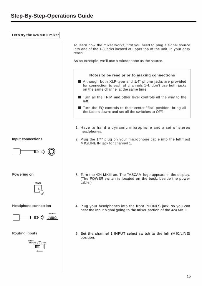
Input connections
Powering on
Headphone connection
Routing inputs
Let’s try the 424 MKIII mixer
To learn how the mixer works, first you need to plug a signal sourceinto one of the 1-8 jacks located at upper top of the unit, in your easyreach.
As an example, we'll use a microphone as the source.
1. Have to hand a dynamic microphone and a set of stereoheadphones.
2. Plug the 1/4" plug on your microphone cable into the leftmostMIC/LINE IN jack for channel 1.
3. Turn the 424 MKIII on. The TASCAM logo appears in the display.(The POWER switch is located on the back, beside the powercable.)
4. Plug your headphones into the front PHONES jack, so you canhear the input signal going to the mixer section of the 424 MKIII.
5. Set the channel 1 INPUT select switch to the left (MIC/LINE)position.
15
Notes to be read prior to making connections
■ Although both XLR-type and 1/4" phone jacks are providedfor connection to each of channels 1-4, don't use both jackson the same channel at the same time.
■ Turn all the TRIM and other level controls all the way to theleft.
■ Turn the EQ controls to their center "flat" position; bring allthe faders down; and set all the switches to OFF.
Step-By-Step-Operations Guide
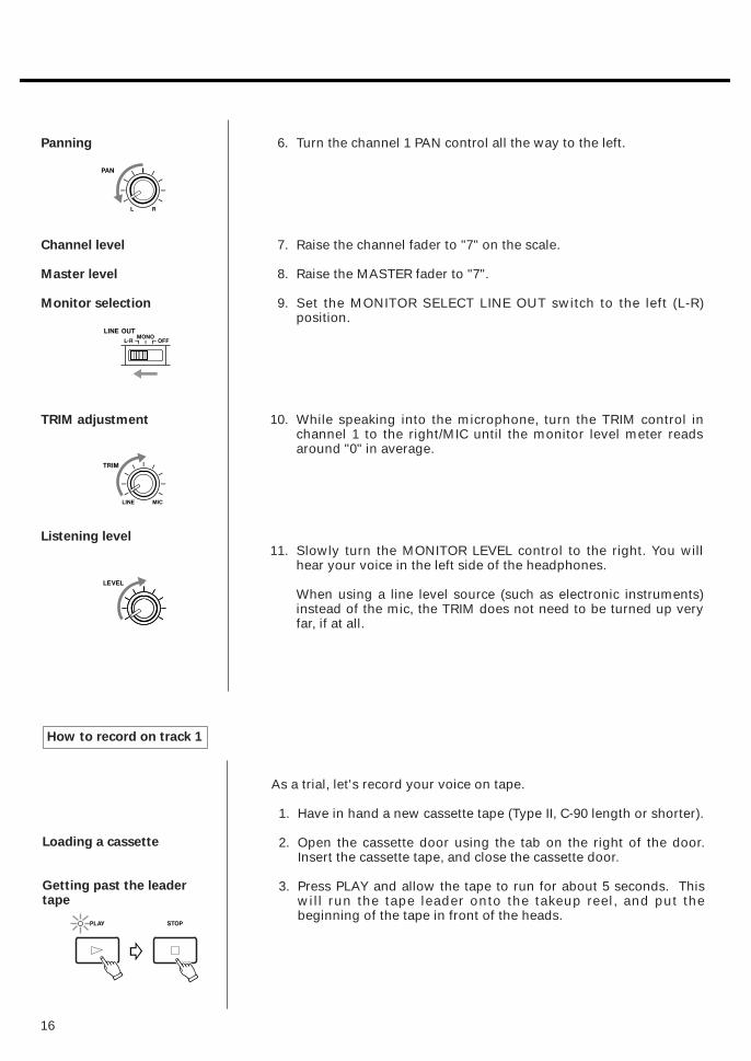
Panning
Channel level
Master level
Monitor selection
TRIM adjustment
Listening level
6. Turn the channel 1 PAN control all the way to the left.
7. Raise the channel fader to "7" on the scale.
8. Raise the MASTER fader to "7".
9. Set the MONITOR SELECT LINE OUT switch to the left (L-R)position.
10. While speaking into the microphone, turn the TRIM control inchannel 1 to the right/MIC until the monitor level meter readsaround "0" in average.
11. Slowly turn the MONITOR LEVEL control to the right. You willhear your voice in the left side of the headphones.
When using a line level source (such as electronic instruments)instead of the mic, the TRIM does not need to be turned up veryfar, if at all.
16
As a trial, let's record your voice on tape.
1. Have in hand a new cassette tape (Type II, C-90 length or shorter).
2. Open the cassette door using the tab on the right of the door.Insert the cassette tape, and close the cassette door.
3. Press PLAY and allow the tape to run for about 5 seconds. Thiswill run the tape leader onto the takeup reel, and put thebeginning of the tape in front of the heads.
Loading a cassette
Getting past the leadertape
How to record on track 1
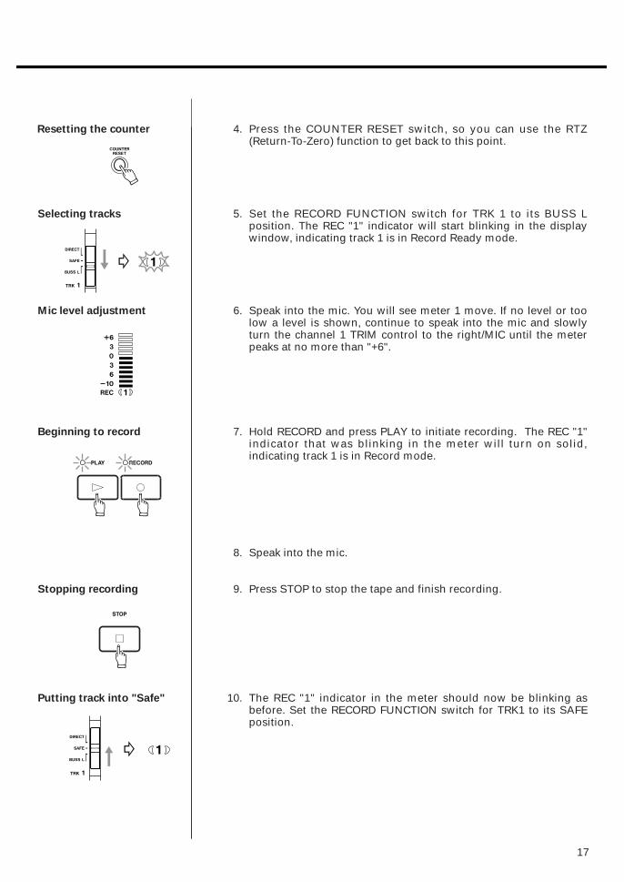
Resetting the counter
Selecting tracks
Mic level adjustment
Beginning to record
Stopping recording
Putting track into "Safe"
4. Press the COUNTER RESET switch, so you can use the RTZ(Return-To-Zero) function to get back to this point.
5. Set the RECORD FUNCTION switch for TRK 1 to its BUSS Lposition. The REC "1" indicator will start blinking in the displaywindow, indicating track 1 is in Record Ready mode.
6. Speak into the mic. You will see meter 1 move. If no level or toolow a level is shown, continue to speak into the mic and slowlyturn the channel 1 TRIM control to the right/MIC until the meterpeaks at no more than "+6".
7. Hold RECORD and press PLAY to initiate recording. The REC "1"indicator that was blinking in the meter will turn on solid,indicating track 1 is in Record mode.
8. Speak into the mic.
9. Press STOP to stop the tape and finish recording.
10. The REC "1" indicator in the meter should now be blinking asbefore. Set the RECORD FUNCTION switch for TRK1 to its SAFEposition.
17
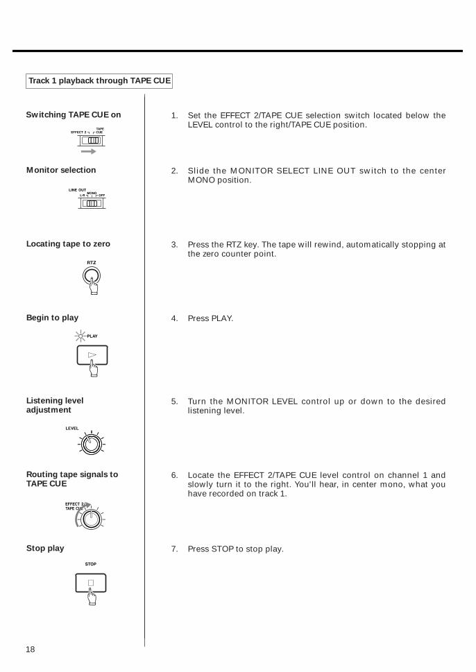
Switching TAPE CUE on
Monitor selection
Locating tape to zero
Begin to play
Listening leveladjustment
Routing tape signals toTAPE CUE
Stop play
Track 1 playback through TAPE CUE
1. Set the EFFECT 2/TAPE CUE selection switch located below theLEVEL control to the right/TAPE CUE position.
2. Slide the MONITOR SELECT LINE OUT switch to the centerMONO position.
3. Press the RTZ key. The tape will rewind, automatically stopping atthe zero counter point.
4. Press PLAY.
5. Turn the MONITOR LEVEL control up or down to the desiredlistening level.
6. Locate the EFFECT 2/TAPE CUE level control on channel 1 andslowly turn it to the right. You'll hear, in center mono, what youhave recorded on track 1.
7. Press STOP to stop play.
18

19
Routing input
Panning
Channel 1 level
Master level
Monitor selection
Locating tape to zero
Track selection
Record level adjustment(TRIM)
How to make an overdub on track 2
Overdubbing entails recording one or more additional tracks on thesame tape, while listening to previously recorded tracks using TAPECUE.
Leave the microphone connected to the channel 1 input. There is noneed to repatch it to channel 2 to record on track 2. You can send anymixer input to any track of the recorder through the combination useof PAN and RECORD FUNCTION.
1. Set the channel 1 INPUT selection switch to the left (MIC/LINE)position.
2. Turn the channel 1 PAN control all the way to the right (R)position.
3. Bring the channel 1 fader to 7.
4. Bring the MASTER fader to 7.
5. Make sure the MONITOR SELECT LINE OUT switch is still in theMONO position.
6. Press the RTZ key, so the tape will rewind to the beginning of thetrack 1 recording.
7. Set the TRK 2 RECORD FUNCTION switch to its BUSS R position.The REC 2 indicator will start blinking in the meter.
8. Speak into the mic to check to see meter 2 move. If no level ortoo low a level is shown, continue to speak into the mic andslowly turn the channel 1 TRIM control to the right until the meterpeaks at no more than +6.
20
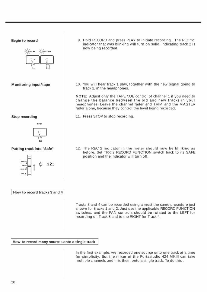
How to record tracks 3 and 4
How to record many sources onto a single track
9. Hold RECORD and press PLAY to initiate recording. The REC "2"indicator that was blinking will turn on solid, indicating track 2 isnow being recorded.
10. You will hear track 1 play, together with the new signal going totrack 2, in the headphones.
NOTE: Adjust only the TAPE CUE control of channel 1 if you need tochange the balance between the old and new tracks in yourheadphones. Leave the channel fader and TRIM and the MASTERfader alone, because they control the level being recorded.
11. Press STOP to stop recording.
12. The REC 2 indicator in the meter should now be blinking asbefore. Set TRK 2 RECORD FUNCTION switch back to its SAFEposition and the indicator will turn off.
Begin to record
Monitoring input/tape
Stop recording
Putting track into "Safe"
Tracks 3 and 4 can be recorded using almost the same procedure justshown for tracks 1 and 2. Just use the applicable RECORD FUNCTIONswitches, and the PAN controls should be rotated to the LEFT forrecording on Track 3 and to the RIGHT for Track 4.
In the first example, we recorded one source onto one track at a timefor simplicity. But the mixer of the Portastudio 424 MKIII can takemultiple channels and mix them onto a single track. To do this :

21
How to record a mix onto two tracks simultaneously
œ Set the PAN control of each channel to the same setting, forexample :
In this example, all instruments plugged intochannels 1-4 will be recorded onto Track 1 or 3.
If you want to record multiple sources onto two tracks, you use thechannel PAN controls to send them to LEFT or RIGHT (or anywhere inbetween, if you're making a stereo mix). The track RECORDFUNCTION switches choose what track the Left and Right mixes willbe recorded on. Note that in this method, the mixer channel numberhas nothing to do with what track the instrument winds up on. Anymixer channel can be panned to any track.
These mixer channels are being sent to the LEFT, for recording on either Track 1 or Track 3.
These mixer channels are being sent to the RIGHT, for recording on either Track 2 or Track 4.
œ Lower the MASTER fader to make overall level adjustments onceyou have each channel's TRIM and fader level set.
œ Make sure the INPUT switch of every channel you want to recordis set to MIC/LINE.
∑ You can't record channels 7 and 8 onto a single track.

22
Recording on more than two tracks simultaneously : DIRECT
∑ Set the MONITOR SELECT LINE OUT switch to L-R or MONO, andset the EFFECT 2/TAPE CUE switch to TAPE CUE if you need tohear tape tracks or MIDI virtual tracks.
Recording is the same procedure as for one track. In the exampleabove, set both the TRK 3 and TRK 4 RECORD FUNCTION switches toBUSS to record on tracks 3 and 4 simultaneously.
Restrictions : The 424 MKIII mixer section has only two main mixes,Left and Right. For this reason, you can record only two tracks at oncewhile you're recording a mix of instruments (for example, twoinstruments on track 1, three instruments on track 2). Also, you canrecord a mix only on combinations or even/odd numbered tracks (1 &2, 1 & 4, 2 & 3 etc.). If the TRK 1 and TRK 3 RECORD FUNCTIONswitches are set to BUSS, the two tracks will both record the samemix.
Recording the stereo channels (5-6 and 7-8) : Channels 5 and 6 can beused to add additional signals to the L and R mixes. The input forthese channels can be odd-numbered inputs 1 through 5 (channel 5)and even-numbered inputs 2 through 6 (channel 6).
Note that if one of the inputs 1 through 4 is selected for use with itsappropriately-numbered channel, as well as with channel 5 or 6, thesignal level will be doubled, as it is being mixed through twochannels together.
Use the stereo channels 7 and 8 to add additional signal sources tothe mix. These channels are automatically panned left and rightrespectively, so you may want to use them with a pre-panned source,such as the stereo outputs of a multi-timbral synthesizer, or a stereoeffects unit.
It is possible to record on three or four tracks at the same time byusing the DIRECT position of the RECORD FUNCTION switches. InDirect recording, each track gets its signal from a single mixerchannel only — Track 3 from channel 3, etc.
∑ When using DIRECT, the MASTER fader has no effect on therecord level. It only affects the level going to theheadphones/monitor speakers. Use the CHANNEL FADER only toset record levels.
∑ Even when using DIRECT, a channel still goes to the Left/Rightmix. If you record another track with BUSS L or BUSS R at thesame time, you must check your PAN settings. For example, youcan record a vocal DIRECT onto Track 3, and record multipleinstruments on Track 1 via BUSS L at the same time. But Channel3's PAN control must be turned hard right, otherwise you'll windup with vocals "bleeding through" onto Track 1's instruments.
∑ DIRECT can be used anytime you want to record a single channelto a single track.

23
Connections
Master level
Monitor source
Routing inputs
Playback level
How to mix down
When the 4 tracks are all recorded, the final step is mixing them into astandard stereo format. This procedure is known as Remixing orMixing down. During this procedure the tracks are blended togetherand balanced to create the desired sound.
1. Connect the LINE OUTPUT L jack of the 424 MKIII to the left lineinput of the mixdown deck, and the LINE OUTPUT R jack to theright line input.
2. Raise the MASTER fader to the shaded area between 7 and 8.
3. Set the MONITOR SELECT LINE OUT switch to the L-R position.
4. Set all the INPUT select switches on the input channels to theright TAPE position.
5. Press PLAY and, while listening to the tape play, tentatively setthe channel faders.
6. Adjust the PAN controls to set each track's left-to-right positionfor the desired stereo image. You may also want to use the EQcontrols to adjust the individual tracks for the desired tonality.(For using effects, see page 35.)
7. Using the MASTER fader, adjust the overall playback level so themonitor level meter averages around "0" and peaks below "+6".

24
Review
Record level
8. When the signal balance, level, and tonality sound right, rewindthe tape, and press PLAY again to check the result.
9. Rewind the multitrack tape again. Put a blank tape in themixdown deck and let it play for 5 seconds, then stop it and resetthe mixdown deck's counter to zero.
10. Press PLAY on the 424 MKIII.
11. Put the mixdown deck into its "Record Ready" mode, and adjustits input level controls for the desired record level.
12. Rewind the multitrack tape to the beginning of the recording.
13. Put the mixdown deck into Record mode then press PLAY on the424 MKIII.
14. When recording is done, stop both machines, rewind themixdown tape and listen to it.
If the mixdown tape does not sound right, make the necessarycorrections and re-do from the beginning.
Using channels 5 and 6 with alternative inputs at mixdown: When channels 1 through 4 are being used to replay previously-recorded tape tracks, channels 5 and 6 can be used to add signalsreceived at the MIC/LINE INPUTS of channels 1–4.
Set the INPUT switch for channel 5 to 1 or 3 or 5, and the INPUTswitch for channel 6 to 2 or 4 or 6.
These signals will appear in the final stereo mix. Use the PAN controlto position them in the desired stereo position.

25
Using Memory Location Points
MEMO 1
MEMO 2
Establishing new MEMOs
Recalculation of MEMOs
Checking MEMO points
Erasing
Loading MEMO points
Two autolocation points can be established in the 424 MKIII's memorysystem.
At the desired moment, hold the MEMO IN key and press the LOC 1key. The MEMO 1 indicator will turn on, showing that the current tapelocation is loaded into that register.
Similarly, if you hold MEMO IN and press LOC 2, the current tapelocation is loaded as memory point 2 into that register.
Each time LOC 1 or 2 is pressed while MEMO IN is held down, a newmemory point is established, and the previous memory point iserased.
MEMO points can't be entered while the tape is locating to eitherMEMO point or during REPEAT.
If the COUNTER RESET button is pressed, both MEMO points areautomatically recalculated, so they stay the same relative to theiroriginal tape positions.
When the tape is stopped, hold down the desired LOC key (for 0.5 second or more). The content of the corresponding MEMOregister will be displayed in the counter window.
Remember : If you don't hold down but just hit the LOC key, the tapeis autolocated to the corresponding MEMO point.
Both MEMO points are erased when the cassette is taken out fromthe compartment or the power is turned off.
26
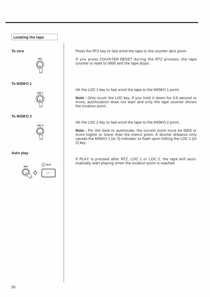
To zero
To MEMO 1
To MEMO 2
Auto play
Locating the tape
Press the RTZ key to fast wind the tape to the counter zero point.
If you press COUNTER RESET during the RTZ process, the tapecounter is reset to 0000 and the tape stops.
Hit the LOC 1 key to fast wind the tape to the MEMO 1 point.
Note : Only touch the LOC key. If you hold it down for 0.5 second ormore, autolocation does not start and only the tape counter showsthe location point.
Hit the LOC 2 key to fast wind the tape to the MEMO 2 point.
Note : For the deck to autolocate, the current point must be 0003 ormore higher or lower than the memo point. A shorter distance onlycauses the MEMO 1 (or 2) indicator to flash upon hitting the LOC 1 (or2) key.
If PLAY is pressed after RTZ, LOC 1 or LOC 2, the tape will auto-matically start playing when the location point is reached.
27
Repeat Play
Operating procedure
To interrupt REPEATsequence
Note 1
Note 2
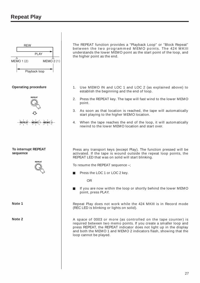
The REPEAT function provides a "Playback Loop" or "Block Repeat"between the two programmed MEMO points. The 424 MKIIIunderstands the lower MEMO point as the start point of the loop, andthe higher point as the end.
1. Use MEMO IN and LOC 1 and LOC 2 (as explained above) toestablish the beginning and the end of loop.
2. Press the REPEAT key. The tape will fast wind to the lower MEMOpoint.
3. As soon as that location is reached, the tape will automaticallystart playing to the higher MEMO location.
4. When the tape reaches the end of the loop, it will automaticallyrewind to the lower MEMO location and start over.
Press any transport keys (except Play). The function pressed will beactivated. If the tape is wound outside the repeat loop points, theREPEAT LED that was on solid will start blinking.
To resume the REPEAT sequence –;
- Press the LOC 1 or LOC 2 key.
OR
- If you are now within the loop or shortly behind the lower MEMOpoint, press PLAY.
Repeat Play does not work while the 424 MKIII is in Record mode(REC LED is blinking or lights on solid).
A space of 0003 or more (as controlled on the tape counter) isrequired between two memo points. If you create a smaller loop andpress REPEAT, the REPEAT indicator does not light up in the displayand both the MEMO 1 and MEMO 2 indicators flash, showing that theloop cannot be played.
28
PUNCH-IN or INSERT Recording
Selecting in and out points
"Punching in" or "insert recording" is recording over a small sectionof previously recorded track to correct or improve a performance,while keeping the rest of the track intact. The mixer settings shouldbe exactly the same as they were during the original recording.
In the following, we'll use track 2 as the punch-in track as an example.
1. As the punch-in track is track 2 in our example, your input mustbe sent to the stereo right bus. To do so, rotate the PAN control ofthe channel into which your source instrument is plugged all theway to the right.
2. TAPE CUE signal path is used to hear the tape, so set the EFFECT 2/TAPE CUE select switch (located below the MONITOR LEVEL control) to the TAPE CUE position and set theEFFECT/CUE monitor switch to EFFECT 2/CUE.
3. To hear the instrument, set the MONITOR SELECT LINE OUTswitch to the MONO position.
4. Press PLAY to play the tape, adjust the TAPE CUE control onchannel 2 until the MONITOR level meters read a maximum offrom 0 to +3, and adjust the MONITOR LEVEL control for thedesired headphone listening level.
5. Play the instrument. You'll hear it together with the tape signalsthrough the headphones. Stop the tape, and you hear only theinstrument being played.
6. Set the TRK 2 RECORD FUNCTION switch to BUSS R. The REC 2indicator will start blinking in the display window, and meter 2will show your instrument's output level. Adjust the channel andMASTER faders for the proper recording level.
For both musical and technical reasons, when punching in or out of atrack, you must select points that are "in the points clear", i.e., inpauses between phrases or notes. Sound seems unnatural andinserts are noticeable if a new note is recorded before the old one hasended, or a note is held as you punch in or out. Making smoothinserts requires practice. Spacing between the erase and recordheads requires that you anticipate in/out points by a fraction of asecond for extremely tight cues. Use the following procedures withthe REHEARSAL switch on.
Preliminary

29
Rehearsing Punch-in(Insert) recording
Storing the punch-in andout points into memory
Rehearsal and Auto In/Out Procedures
You can rehearse your punch-in as many times needed withoutaffecting the existing recording. During rehearsal, what you hear inthe monitor mix and read on the level meters will be the same asduring recording, but signal won't be recorded on tape.
1. Cue the tape up a few seconds before you reach the expectedpunch-in point.
2. Press the REHEARSAL switch. The "RHSL" indicator will startblinking in the display.
3. Press PLAY to start playing ("preroll"). The "START" indicator willglow on the display. The counter readout at which the key waspressed is stored as the START point. The MEMO 1 or 2 indicatorturns off (if it was lit).
4. When you reach JUST BEFORE the error, press RECORD to startrecording (punch in). The "IN" indicator will glow on the displayand an LED will start flashing above the RECORD button. Thecounter readout at which the key was pressed is stored as thePUNCH-IN point.
5. When the tape reaches the expected punch-out point, press PLAY.The "OUT" indicator will turn on, and the "IN" indicator and theLED above the RECORD button will turn off. The counter readoutat which the key was pressed is stored as the PUNCH-OUT point.
6. The tape will play for about 3 seconds ("postroll"), then willautomatically rewind, stopping at the START point. The "RHSL"indicator that was blinking will glow solid in the display.
7. Press PLAY (or REPEAT if you want to practice the performanceover and over again, continuously). When the tape reaches thepreset punch-in point, the monitor will switch from tape to "live"instrument on the punch-in track (in our example, on track 2).
The RECORD LED will blink to indicate that you are "rehearsing"punch-in recording, not actually recording.
Rehearsal

30
When the tape reaches the preset punch-out point, you will beable to hear the old material existing on track 2, letting you checkthat the new material is smoothly followed by the old one. TheRECORD LED will turn off, indicating that the "dry-run" record isover.
After 3 seconds of play ("postroll") the tape will automaticallyrewind, stopping at the START point, so you can again gothrough the rehearsal procedure.
● To change the punch-in and out points, press CLEAR, andrestart from the beginning.
● If you want to quit Rehearsal mode for any reason, pressCLEAR. "RHSL" goes out and the start, punch-in and out pointsare cleared from memory.
- Practice the performance until you are sure that you will get itright when actually recording. Remember, punching-in overexisting material erases the original signal.
- When the REHEARSAL key is pressed during playback, thecounter readout at which the key is pressed is stored as theSTART point.
- You can store the Punch-In/Out or Rehearsal point also using theoptional remote footswitch (RC-30P).
Suggestion: During the punch-in setting or the rehearsal process,if you press the footswitch after STOP, the tape will rewind toyour START point.
- Rehearsal function is not available while the 424 MKIII is in thelocate, repeat or record mode.
- Locate or repeat function is not available while storing Punch-In/Out points in memory.
- After the Punch-In/Out points have been stored in memory, the424 MKIII cannot enter the record mode (whereby RECORD LEDblinks or glows).
- If you press any of the transport keys during storage of theRehearsal (Punch-In/Out) points, the 424 MKIII will start operationcorresponding to the key pressed. However, only when the REWkey is pressed, the tape will rewind, stopping at that Start point.
Once you're sure your performance and the in/out points selected arecorrect, you're ready to actually record the insert using the AutoPunch-In/Out feature.
Before proceeding to the next step, #8, check to see that the RHSLindicator is on solid in the display, showing that your punch-in andout points are in memory, and that all REC indicators beneath themeters are off (except the one for the punch-in track), showing that allnon-punch-in tracks are in Safe mode.
Actual Auto Punch In/Out

31
Manual Punch-in
8. Press the AUTO PUNCH switch. "RHSL" will turn off and "AUTO"will start blinking in the display.
9. Press PLAY.
What you have anticipated in REHEARSAL will automaticallyoccur in sequence: preroll, punch in, punch out, postroll, rewind,and stop.
"AUTO" will be solidly displayed when the 424 MKIII punches outof record.
10. Press PLAY (or the optional footswitch). The tape will play theentire length of insert and rewind to the START point.
After completing auto review if you want to re-do the autopunch-in and out using the same settings, press the AUTOPUNCH switch once more and "AUTO", which was lit steadily,starts flashing as before, showing that the auto punch-in processwill restart when pressing PLAY.
● To Disable AUTO PUNCH Mode, press CLEAR. The memorypoints will be cleared and "AUTO" will turn off in the display.
The 424 MKIII lets you manually punch in, too. There are 2 ways toinitiate the punch-in recording. The first is with the transport RECORDbutton, and the second is with the optional footswitch.
We always use track 2 as the punch-in track in the following example.
Perform the "Preliminary" on page 28, if you haven't yet done so.
1. Check to see that the REC 2 indicator is blinking showing track 2is in Rec Ready mode. Locate the tape a little behind the expectedpunch-in point. Then press PLAY.
2. When you reach JUST BEFORE the error, press RECORD. TheREC 2 indicator that was blinking will be solidly displayed andtrack 2 enters Record mode.
3. To punch-out of record, press PLAY. The REC 2 indicator that wassolidly displayed again blinks to indicate that recording is over.
4. To stop the tape, press STOP.
Auto Review
Punching-in/out withRECORD
32
Using the remotefootswitch (RC-30P)
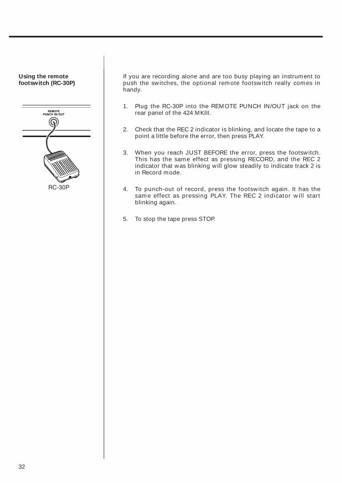
If you are recording alone and are too busy playing an instrument topush the switches, the optional remote footswitch really comes inhandy.
1. Plug the RC-30P into the REMOTE PUNCH IN/OUT jack on therear panel of the 424 MKIII.
2. Check that the REC 2 indicator is blinking, and locate the tape to apoint a little before the error, then press PLAY.
3. When you reach JUST BEFORE the error, press the footswitch.This has the same effect as pressing RECORD, and the REC 2indicator that was blinking will glow steadily to indicate track 2 isin Record mode.
4. To punch-out of record, press the footswitch again. It has thesame effect as pressing PLAY. The REC 2 indicator will startblinking again.
5. To stop the tape press STOP.

33
The recording capability of the PORTASTUDIO 424 MKIII is not limitedto four tracks. You can "bounce" or combine tracks you have recordedto an empty track, and then replace the original tracks with newmaterial. A bounce is like a mixdown, except you are recording to oneof the tracks of the 424 MKIII instead of to an external recorder. Thefollowing diagrams depict the process.
During a bounce you can add live sources along with the prerecordedtracks, using the "empty" mixer channels not being used for tapeplayback. This gives you even more ways to add layers to acomposition. For example, you can bounce tracks 1-3 along withanother "live" part onto track 4, for a total of four parts on one track.
Bouncing Tracks (Ping-Pong)
Ping-pong procedure
In this example, we will combine material from tracks1-3 onto track 4.
1. On channels 1-3, make the following settings :
œ INPUT to TAPE,
œ PAN all the way to R, and
œ Input fader to the shaded zone (7-8 on the scale).
2. Push the MASTER fader to the shaded zone.
3. Set the MONITOR SELECT LINE OUT switch to the MONOposition.
4. Set the RECORD FUNCTION switch for track 4 to BUSS R. TheREC 4 indicator will start blinking in the meter window, indicatingthe track is in Rec Ready mode.
5. Press PLAY. The tape will start playing.
TRK 1 A2 B3 C4
Bouncing tracks 1-3onto track 4
DEFA + B + C
Tracks 1-3 available forrecording new parts
®

34
6. Use channel faders 1 through 3 to make any necessary leveladjustments. You may want to repeat this step several times toget the balance correct.
7. When the balance is right and the level is peaking at no morethan +6 on the track 4 meter, stop and rewind the tape to thebeginning of the track.
8. Hold RECORD and press PLAY. The REC 4 indicator that wasblinking will turn on solid and track 4 will record a copy of what ison tracks 1-3.
9. You'll hear the mix being recorded on track 4 in the headphones.
10. Once the recording is done, press STOP.
11. The REC 4 indicator will now be blinking as before. Turn that offby setting the RECORD FUNCTION switch for track 4 to SAFE.
When bouncing tracks, remember that live material can be addedfrom channels 5 and 6, as well as from 7-8. Channels 5 and 6 canuse the signal sources connected to inputs 1 through 4, using theINPUT switches for channels 5 and 6.
Using Effects With the PORTASTUDIO 424 MKIII
35
Effects and signal processing are areas whereyou can really start to have fun customizing yoursound, and develop your own unique recordingstyle. Because there are so many possibilities, italso can be confusing. There are many differenteffect units on the market, all with differentcontrols, types of inputs and outputs, and othercharacteristics. Read the manual of your effectsdevice, and the following sections to get thecomplete story of what's possible for yourparticular situation.
1. In-line processing: The processing that'seasiest to understand doesn't involve the 424MKIII directly at all. You can plug yourinstrument directly into the input of the effectdevice, and plug the output of the devicedirectly into a line input of the 424 MKIII. Thewhole signal gets processed (flanged,doubled, limited, delayed etc.), and only oneinstrument can use that processor. Effectpedals for guitar are typically used this way.To get a mix of processed ("wet") and original("dry") signal, the unit must have its own MIXor BALANCE control.
2. Send/return mix processing: This is the mostcommon method of effect processing,especially for reverb and delay. It allows anumber of different channels to use the sameeffect, while allowing you to control howmuch effect is mixed with each channel.Each of the 4 mixer channels can sendsignals to the EFFECT SEND 1 or 2 outputs onthe upper top panel. These outputs can thenbe connected to the input of effect devices.The processed signals from the devices comeback into the mix via the STEREO INPUTS.Finally, the effect is mixed onto the stereo leftor right buss with the ASSIGN switch on thestereo channels (7-8). This whole path—fromthe EFFECT SENDS to the reverb and backinto STEREO INPUTS — is called an effectsloop. The EFFECT 1 and 2 controls determinehow much signal goes to the reverb unit; theLEVEL control on the stereo channelsdetermine how much returns from the reverbunit. In this method, the stereo inputsfunction as effect returns.
Setting effect send levels
Setting the output level of effect devices
The goal is not to distort the device, whilestaying above the noise that effect unitsgenerate. To get the best signal-to-noise frommost effects units, you should send it as strong asignal as you can. With a properly set inputsignal in the 424 MKIII, the channel EFFECT sendset to about 2 o'clock position (for EFFECT 1 orEFFECT 2 feed), you should get a fairly loudsignal from the EFFECT SEND jacks.
If your effects device has an input level control ofits own, it should be set so the meter or signallight of the effects device is just under theoverload point on peak signals. When you wantto hear less effect overall, turn down the returnLEVEL control on the stereo channels.
If the effect send level has been set properly, inmost cases the output level of the effect unitshould be set as high as possible withoutclipping (distorting) the STEREO INPUTS of the424 MKIII, but low enough so that you have areasonable range of control. If you can get theeffect sound you want with the return LEVELcontrol in the 12 to 2 o'clock range, you're in theballpark. If, on the other hand, very smallsettings of the Effects Return still give you a mixdrowning in effects, turn down the output levelof your effect device.
Some effect units have rear panel switchessetting input and output level ranges between"+4" and "–20 dB". In this case, try setting theinput to –20 (high sensitivity) and the output to+4 (full output level).
When it's being used in a send-return mix, setthe mix/balance of your effect device all the wayto "wet" or full processing with no direct originalsignal. In send/receive processing, the dry signalgoes down the 424 MKIII's channel fader to bemixed with the effect return signal on the stereomix. Therefore, you don't need any "dry" signalcoming to the effects return. The mix/balancecontrol is set toward "dry" only when you'reusing the effects device as an in-line processor.
Setting the mix/balance control on effectdevices
36
To record reverb onto a track : Switch theASSIGN switch to L-R, and adjust thecontrols for the sound you want. Rememberthat stereo signals must be recorded ontotwo tracks to keep their "stereo" effect.
To hear reverb in the headphones but not recordthe reverb : Set the ASSIGN switch on thestereo channel being used for returningeffects to the right/MON position, turning upthe LEVEL control on the stereo channel inuse.
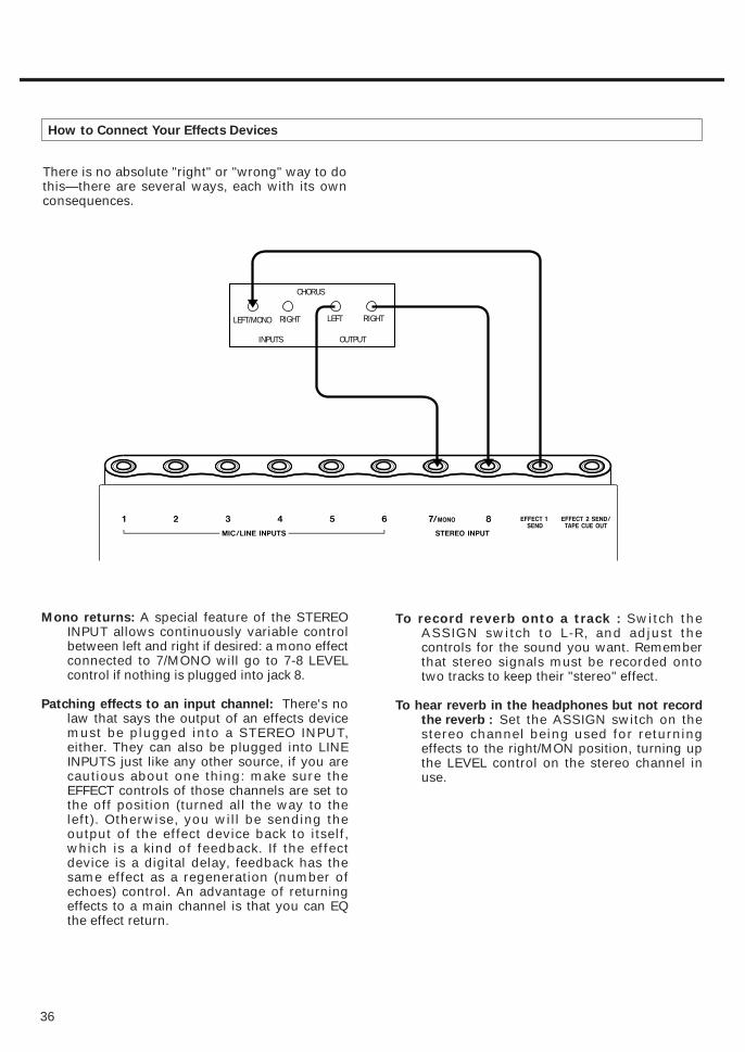
Mono returns: A special feature of the STEREOINPUT allows continuously variable controlbetween left and right if desired: a mono effectconnected to 7/MONO will go to 7-8 LEVELcontrol if nothing is plugged into jack 8.
Patching effects to an input channel: There's nolaw that says the output of an effects devicemust be plugged into a STEREO INPUT,either. They can also be plugged into LINEINPUTS just like any other source, if you arecautious about one thing: make sure theEFFECT controls of those channels are set tothe off position (turned all the way to theleft). Otherwise, you will be sending theoutput of the effect device back to itself,which is a kind of feedback. If the effectdevice is a digital delay, feedback has thesame effect as a regeneration (number ofechoes) control. An advantage of returningeffects to a main channel is that you can EQthe effect return.
How to Connect Your Effects Devices
There is no absolute "right" or "wrong" way to dothis—there are several ways, each with its ownconsequences.
CHORUS
LEFT/MONO RIGHT
INPUTS
LEFT RIGHT
OUTPUT

Problem Solution
Old tracks are always recorded along Use the TAPE CUE section instead of the with new material. main mixer for monitoring previous tracks.
Make sure all mixer channel INPUT switchesare in the OFF position except ones you are
Recording is noisy. using. Also, increase the volume faders ofthe instruments themselves — the 424 MKIII channel and master faders should not have to be "full up" at any time.
Incorrect tape sync. Try re-recording sync tones by adjusting the MASTER fader between –10 to 0 dB on the track 4 meter.
Problem Possible Cause
Playback sounds dull Dirty heads
Playback level is low Dirty heads
Transport keys not effective Power turned off, or tape not loaded
No tape motion PAUSE pressed
RECORD FUNCTION set to SAFE,No recording cassette tab broken, or REHEARSAL
engaged
Wrong tracks recorded PAN improperly set
Incorrect playback pitch PITCH CONTROL set to a differentposition than during recording
Feedback occurs during ping-pong Level is too high or EQ HIGH is recording excessively boosted
38
Troubleshooting
37
Syncing MIDI-Tape1Using the TASCAM MTS-30
MIDI clocks are themselves a computer type digital language andcannot be recorded on analog tape; it is necessary to convert them torecordable FSK (Frequency Shift Keying) signals using an appropriateconverter, such as the MTS-30.
The MTS-30 is not a mere MIDI-FSK converter but translates MIDIclocks into an FSK sync signal containing score "bar" information or"Song Position Pointer", allowing the associated MIDI equipment tostay in sync and follow the tape no matter where you move the tapewithin a given song. The maximum stability or resolution of thesynchronization is ensured by a TASCAM-exclusive error correctioncircuit in the MTS-30.
1. Connect the TAPE OUT of the MTS-30 to the SUB IN "R" of the424 MKIII, and the TAPE OUT 4 of the 424 MKIII to the TAPE IN ofthe MTS-30.
2. Set the TRK 4 RECORD FUNCTION switch to BUSS R.
3. Locate the DBX NR switch on the back panel and set it to theSYNC position. This defeats the dbx encode/decode for track 4only.
● When recording FSK signal, adjust the MASTER fader of the 424MKIII to get a reading on the track 4 meter of from -10 to 0 dB.
We suggest that you input the "virtual" tracks from the MIDI system toSTEREO INPUTS 7 and 8. Set the ASSIGN switch of these inputs toMON while recording, and to L-R position on mixdown.

424 MKIII MIXER
1. POWER switch (on the rear panel): Turns the424 MKIII on and off.
2. Power connector: Connect the power adaptorfor the 424 MKIII to this connector. It isimportant that you use only a power adaptorspecially designed for the 424 MKIII which isdesigned for use with the voltage in yourarea.
3. MIC/LINE INPUTS jacks, Balanced (Channels
1-4): The 3-contact XLR-type connectoraccepts balanced microphone signalsranging from –60 dBV (1 mV) to –20 dBV (100 mV), depending on the setting of theTRIM control (#6).
4. MIC/LINE INPUTS jacks, Unbalanced
(Channels 1-4): This 1/4" jack acceptsunbalanced signals ranging from –50 dBV (3 mV) to –10 dBV (0.3 V), depending on thesetting of the TRIM control (#6).
5. SUB INPUT L and R jacks: These jacks are forcascade connection of an outboard mixer,etc. The signal input to these jacks is sent tothe MASTER fader. Nominal input level is –10 dBV (0.3 V).
The SUB IN R jack is also used to accept FSK-converted MIDI sync signals from devicessuch as the optional TASCAM MIDI-TapeSynchronizer MTS-30.
6. TRIM controls: This is used to setpreamplification level on the MIC/LINEINPUTS. When TRIM is turned all the way tothe left (LINE position), the preamplifier gainis low, allowing the jack to accept line levelsources such as electronic instruments. Asyou turn TRIM up, the preamplifier gainincreases, and when you turn TRIM fullclockwise (MIC position), the nominal inputsensitivity increases to –50 dBV (3 mV) for1/4" phone jack, and to –60 dBV (1 mV) forXLR-type jack.
NOTE
■ DO NOT use both the XLR-type and 1/4"phone jacks on the same channel at thesame time.
Input Section
39
Features and Controls
40
7. INPUT select switches:
(channels 1-4)
This is used to control what the source of thechannel is:
The left position (MIC/LINE) is used whenrecording microphones/instruments (intracking or overdubbing).
The center position (OFF) is used to shut offthe channel.
The right position (TAPE) is used duringmixdown or bouncing tracks.
(channels 5 and 6)
This is used to control the source of thesechannels. Channel 5 can accept the signalsfrom equipment connected to odd-numberedinputs 1, 3 and 5, and channel 6 uses theeven-numbered inputs in the same way. Slidethe switch to the appropriate number to sendthe signal from the appropriately-numberedinput to the channel.
Note that if signals are sent through morethan one channel at the same time (e.g.through channel 1 and 5), the level of thesesignals will be doubled. You should allow forthis when mixing.
8. EQ HIGH: This controls the tonality of thehigh or "treble" frequencies. Turn it to theright to boost the signal's high frequencycontent emphasizing brilliance or brightness.Turn it to the left to cut the high frequencycontent, if the signal sounds too harsh orshrill. The EQ shelving point is 10 kHz.
9. EQ MID: The upper knob changes the centerfrequency of the MID equalizer from 250 Hzto 5 kHz. The lower knob controls how muchcut or boost is applied to the band chosen bythe upper knob. Turning the lower knob tothe right amplifies the band up to 12 dB.Turning it to the left cuts the band down to–12 dB. At center, there is no effect (flatresponse).
10. EQ LOW: Turn the control to the right toboost bass frequencies and make the soundrelatively heavy. Turn the control to the left tocut bass and make the sound thinner. The EQshelving point is 100 Hz.
11. EFFECT 1 send controls: These controls gettheir signal from a point just after thechannel fader (i.e., "post fader send") androute the corresponding channel signal tothe EFFECT 1 SEND jack. Turn the control tothe right to increase volume to the EFFECT 1SEND jack.
12. EFFECT 2/TAPE CUE controls: These controlsget their signal after the channel fader androute the signal to the EFFECT 2 SEND jack,or are used to adjust the tape playback levelsent to the monitor section, as determinedby the MONITOR EFFECT 2/TAPE CUE selectswitch.
13. PAN controls: This control allows you tocreate stereo mixes by sending the signalfrom the channel fader in continuouslyvariable degrees to the left or right sides ofthe stereo mix at mixdown time.
14. Channel Faders:This linear control varies thelevel feeding the Master section.The nominal setting position is between 7and 8 (shaded area).
15. STEREO INPUT jacks: Connect the outputs ofyour effects devices to these 1/4" jacks. These jacks can also be used as additionalline inputs. Nominal input level is –10 dBV(0.3 V).
Mono Feature: If you connect a mono signalto the 7/MONO jack, the signal is sent to boththe stereo left and right busses.
16. LEVEL control: This rotary control varies thelevel feeding the Master section. The nominal setting position is about 2o'clock.
17. ASSIGN switch: This send the signal fromthe LEVEL control to the MASTER (L-R),switches it off entirely (OFF) or to theMONITOR LEVEL control (MON). If you areusing these inputs for MIDI “virtual tracks”,you should probably set this switch to MONwhile recording tape tracks, and L-R onmixdown.
Stereo Input Section
18. MONITOR SELECT switches: These switchesdetermine what you will hear whenmonitoring.
The LINE OUT switch allows you to monitorin stereo (L-R), in mono (MONO) or turn offthe L-R signals completely from themonitoring mix (OFF).
The EFFECT/CUE switch allows you tochoose whether you will hear the EFFECT 1send, the EFFECT 2 or TAPE CUE send (asdetermined by the position of the EFFECT2/TAPE CUE switch), or neither of these(OFF).
19. MONITOR LEVEL control: This affects signalfrom the MONITOR select switch and setsthe level you'll hear in theheadphones/monitor speakers.
20. EFFECT 2/TAPE CUE select switch : Depend-ing on the setting of this switch, eachchannel's EFFECT 2/TAPE CUE control isswitched to send the mic/line input to effectsdevices or the signal coming back from therecorder to the musicians in studio.
21. MASTER fader : Used to adjust the stereomix level. The signal fed to this fader comesfrom each channel's PAN control. The safeoperating zone is between 7-8 on the scale.
22. LINE OUTPUT L and R jacks: These jacks arethe line-level outputs from the MASTERfader. The L and R jacks are typicallyconnected to your 2-track master recorder atMIXDOWN. The LINE OUTPUT jacks can alsobe used to send the mixer outputs of the 424 MKIII to the sub inputs of a larger mixer.
23. MONITOR OUTPUT L and R jacks: Theseprovide a line level version of the samesignal that feeds the PHONES jack and maybe connected to your control room speakeramplifier.
Output Section
Master Section
Monitor Section
41
42
424 MKIII RECORDER
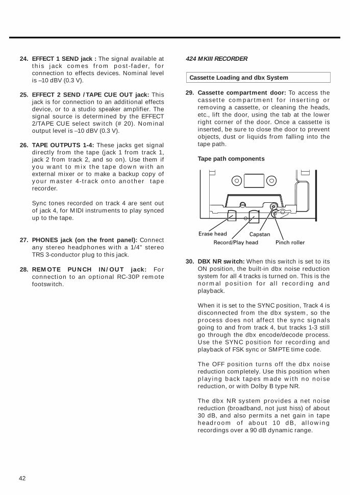
29. Cassette compartment door: To access thecassette compartment for inserting orremoving a cassette, or cleaning the heads,etc., lift the door, using the tab at the lowerright corner of the door. Once a cassette isinserted, be sure to close the door to preventobjects, dust or liquids from falling into thetape path.
Tape path components
30. DBX NR switch: When this switch is set to itsON position, the built-in dbx noise reductionsystem for all 4 tracks is turned on. This is thenormal position for all recording andplayback.
When it is set to the SYNC position, Track 4 isdisconnected from the dbx system, so theprocess does not affect the sync signalsgoing to and from track 4, but tracks 1-3 stillgo through the dbx encode/decode process.Use the SYNC position for recording andplayback of FSK sync or SMPTE time code.
The OFF position turns off the dbx noisereduction completely. Use this position whenplaying back tapes made with no noisereduction, or with Dolby B type NR.
The dbx NR system provides a net noisereduction (broadband, not just hiss) of about30 dB, and also permits a net gain in tapeheadroom of about 10 dB, allowingrecordings over a 90 dB dynamic range.
Cassette Loading and dbx System
24. EFFECT 1 SEND jack : The signal available atthis jack comes from post-fader, forconnection to effects devices. Nominal levelis –10 dBV (0.3 V).
25. EFFECT 2 SEND /TAPE CUE OUT jack: Thisjack is for connection to an additional effectsdevice, or to a studio speaker amplifier. Thesignal source is determined by the EFFECT2/TAPE CUE select switch (# 20). Nominaloutput level is –10 dBV (0.3 V).
26. TAPE OUTPUTS 1-4: These jacks get signaldirectly from the tape (jack 1 from track 1,jack 2 from track 2, and so on). Use them ifyou want to mix the tape down with anexternal mixer or to make a backup copy ofyour master 4-track onto another taperecorder.
Sync tones recorded on track 4 are sent outof jack 4, for MIDI instruments to play syncedup to the tape.
27. PHONES jack (on the front panel): Connectany stereo headphones with a 1/4" stereoTRS 3-conductor plug to this jack.
28. REMOTE PUNCH IN/OUT jack: Forconnection to an optional RC-30P remotefootswitch.

This can be used to save slightly out-of-tuneparts, or to create sound effects such asflanging. Note that if you record with the dialat its maximum or minimum setting, you willNOT be able to make further adjustment inthat direction upon playback.
CAUTION: The PITCH CONTROL dial affectsrecording speed also. Check to make surethat the dial is at its center "0" position unlessyou are using the function intentionally.
37. TAPE SPEED select switch: Controls thespeed of the transport in both record andplayback.
HIGH (3-3/4 i.p.s., 9.5 cm/sec.) is the positionyou should use for master recording, since itoffers slightly better frequency response andsignal-to-noise ratio than standard speed. Inhigh speed, a C-60 offers 15 minutes of 4-track recording.
NORMAL is standard cassette speed of 1-7/8i.p.s. (4.8 cm/sec.). It offers compatibility withother cassettes, acceptable sound quality forless critical work, and 30 minutes ofrecording on a C-60.
43
31. REW key: Winds tape at high speed inreverse direction.
32. F FWD key: Winds tape at high speed in theforward direction.
33. STOP key: Stops any tape motion anddisables all transport modes.
34. PLAY key:
a) Press this key alone to start playback. b) If pressed together with RECORD,
recording ("punch in") starts. c) Press this key during recording to stop
recording ("punch out") without stoppingtape motion.
35. RECORD key: Pressing this key alone has noeffect. Pressing it together with PLAY (4)activates either of two functions:
1) Recording begins if one or more RECORDFUNCTION switches (#38) are previouslyset to a different position from SAFE andthe track indicators blink in the meterwindow.
- Recording can also be initiated by pressingRECORD during PLAY. See "PUNCH-IN orINSERT Recording", page 28.
2) If all RECORD FUNCTION switches (#38)are in the SAFE position, the recorder willenter Record standby mode as indicatedby a blinking RECORD LED.
36. PITCH CONTROL dial: Varies tape speed inrecord and play modes by up toapproximately 12%. Turn the dial to the left tolower the speed, or to the right to increasethe speed. Set the dial to the center "0"position to run tape at a standard speed of9.5 or 4.8 cm/sec., as selected by the TAPESPEED switch.
Transport Controls
44
Autolocators
41. Monitor level meters: These show the levelin the monitor mix selected by the MONITORswitches (#18). The meters are "Pre" (before)the rotary MONITOR LEVEL control, so thiscontrol does not affect the meter readings.
42. Tape counter: Displays the distance the tapehas moved from a zero reference pointselected by pressing the COUNTER RESETkey beneath.
43. Other indicators: Light up or blink dependingon the selected mode and condition of your424 MKIII.
44. RTZ (Return-To-Zero) key: When this key ispressed in any transport mode, the tape willfast wind to the counter's zero (0000) point.
45. LOC 1 key: If pressed while the MEMO IN key(#47) is held down, it loads the current tapelocation into MEMO 1 register.
If pressed alone, it causes the tape to fastwind in either direction to the MEMO 1 point(if this point has been memorized).
This key is also used to check the memopoint.
NOTE: To initiate autolocation, HIT the LOCkey. To check the memo point, PRESS the keyfor 0.5 second or more.
46. LOC 2 key: Similar to the LOC 1 key, this keyis used to establish a MEMO 2 point, and tolocate tape with that memory point.
47. MEMO IN key: Used together with the LOC 1and LOC 2 keys to load the current tapelocation into memory. See #45 and 46 above.
48. REPEAT switch: This provides a "playbackloop" or "block repeat" between MEMO 1 andMEMO 2 points.
Track Controls
38. RECORD FUNCTION switches 1-4: Theseswitches put the respective tracks into RecordReady. Recording starts when RECORD ispressed after or together with PLAY.
In the center position (SAFE) no recordingtakes place.
NOTE: Don't operate the RECORD FUNCTION
switches to punch in and out. Otherwise,
"clicks" will remain on tape.
The RECORD FUNCTION switches also selectwhat source will be recorded. For example,Track 1 can record either the single sourceplugged into Channel 1 of the mixer(DIRECT), or the entire BUSS L mix (whichmay have as many as six sources). The otherRECORD FUNCTION switches work in thesame way: either DIRECT from the same-numbered mixer channel, or from theMASTER stereo mix: Tracks 1 & 3 from BUSSL, Tracks 2 & 4 from BUSS R.
39. Track REC indicators: They show theindividual track's status as selected by theRECORD FUNCTION switches (#38).
40. Track level meters 1-4: These meters showthe record level coming either from eachchannel's fader or from the MASTER fader(the first and the third meters register thelevel from the left buss, the second and thefourth meters register the level from the rightbuss). If a track or tracks are in Safe mode thecorresponding meters show the playbacklevel.
Displays
Track REC Track statusindicator
Off Safe
Blinking Record Stand-by
Steady indication Record
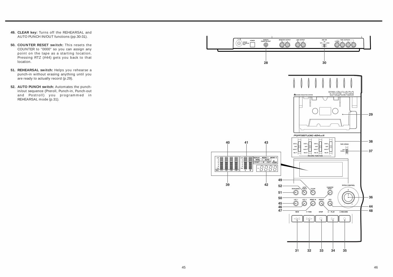
4645
49. CLEAR key: Turns off the REHEARSAL andAUTO PUNCH IN/OUT functions (pp.30-31).
50. COUNTER RESET switch: This resets theCOUNTER to "0000" so you can assign anypoint on the tape as a starting location.Pressing RTZ (#44) gets you back to thatlocation.
51. REHEARSAL switch: Helps you rehearse apunch-in without erasing anything until youare ready to actually record (p.29).
52. AUTO PUNCH switch: Automates the punch-in/out sequence (Preroll, Punch-in, Punch-outand Postroll) you programmed inREHEARSAL mode (p.31).
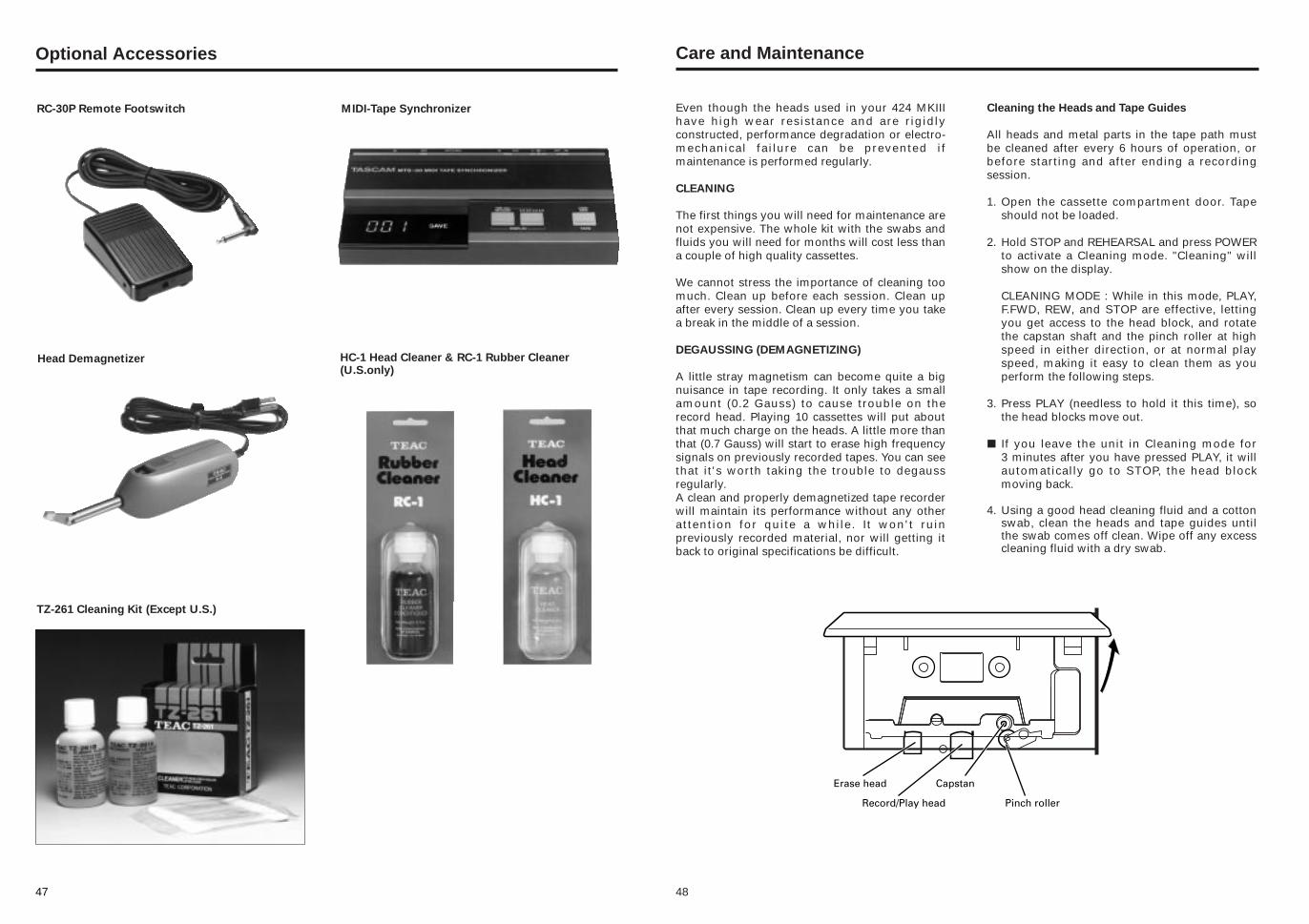
47
Optional Accessories
TZ-261 Cleaning Kit (Except U.S.)
HC-1 Head Cleaner & RC-1 Rubber Cleaner(U.S.only)
Head Demagnetizer
RC-30P Remote Footswitch MIDI-Tape Synchronizer Cleaning the Heads and Tape Guides
All heads and metal parts in the tape path mustbe cleaned after every 6 hours of operation, orbefore starting and after ending a recordingsession.
1. Open the cassette compartment door. Tapeshould not be loaded.
2. Hold STOP and REHEARSAL and press POWERto activate a Cleaning mode. "Cleaning" willshow on the display.
CLEANING MODE : While in this mode, PLAY,F.FWD, REW, and STOP are effective, lettingyou get access to the head block, and rotatethe capstan shaft and the pinch roller at highspeed in either direction, or at normal playspeed, making it easy to clean them as youperform the following steps.
3. Press PLAY (needless to hold it this time), sothe head blocks move out.
∑ If you leave the unit in Cleaning mode for 3 minutes after you have pressed PLAY, it willautomatically go to STOP, the head blockmoving back.
4. Using a good head cleaning fluid and a cottonswab, clean the heads and tape guides untilthe swab comes off clean. Wipe off any excesscleaning fluid with a dry swab.
Even though the heads used in your 424 MKIIIhave high wear resistance and are rigidlyconstructed, performance degradation or electro-mechanical failure can be prevented ifmaintenance is performed regularly.
CLEANING
The first things you will need for maintenance arenot expensive. The whole kit with the swabs andfluids you will need for months will cost less thana couple of high quality cassettes.
We cannot stress the importance of cleaning toomuch. Clean up before each session. Clean upafter every session. Clean up every time you takea break in the middle of a session.
DEGAUSSING (DEMAGNETIZING)
A little stray magnetism can become quite a bignuisance in tape recording. It only takes a smallamount (0.2 Gauss) to cause trouble on therecord head. Playing 10 cassettes will put aboutthat much charge on the heads. A little more thanthat (0.7 Gauss) will start to erase high frequencysignals on previously recorded tapes. You can seethat it's worth taking the trouble to degaussregularly.A clean and properly demagnetized tape recorderwill maintain its performance without any otherattention for quite a while. It won't ruinpreviously recorded material, nor will getting itback to original specifications be difficult.
Care and Maintenance
48
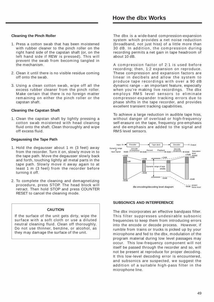
49
The dbx is a wide-band compression-expansionsystem which provides a net noise reduction(broadband, not just hiss) of a little more than 30 dB. In addition, the compression duringrecording permits a net gain in tape headroom ofabout 10 dB.
A compression factor of 2:1 is used beforerecording; then, 1:2 expansion on reproduce.These compression and expansion factors arelinear in decibels and allow the system toproduce tape recordings with over a 90 dBdynamic range – an important feature, especiallywhen you're making live recordings. The dbxemploys RMS level sensors to eliminatecompressor-expander tracking errors due tophase shifts in the tape recorder, and providesexcellent transient tracking capabilities.
To achieve a large reduction in audible tape hiss,without danger of overload or high-frequencyself-erasure on the tape, frequency pre-emphasisand de-emphasis are added to the signal andRMS level sensors.
Cleaning the Pinch Roller
1. Press a cotton swab that has been moistenedwith rubber cleaner to the pinch roller on theright hand side of the capstan shaft (or, on theleft hand side if REW is pressed). This willprevent the swab from becoming tangled inthe mechanism.
2. Clean it until there is no visible residue comingoff onto the swab.
3. Using a clean cotton swab, wipe off all theexcess rubber cleaner from the pinch roller.Make certain that there is no foreign matterremaining on either the pinch roller or thecapstan shaft.
Cleaning the Capstan Shaft
1. Clean the capstan shaft by lightly pressing acotton swab moistened with head cleaningfluid onto the shaft. Clean thoroughly and wipeoff excess fluid.
Degaussing the Tape Path
1. Hold the degausser about 1 m (3 feet) awayfrom the recorder. Turn it on, slowly move in tothe tape path. Move the degausser slowly backand forth, touching lightly all metal parts in thetape path. Slowly move it away again to atleast 1 m (3 feet) from the recorder beforeturning it off.
2. To complete the cleaning and demagnetizingprocedure, press STOP. The head block willretract. Then hold STOP and press COUNTERRESET to cancel the cleaning mode.
How the dbx Works
CAUTION
If the surface of the unit gets dirty, wipe thesurface with a soft cloth or use a dilutedneutral cleaning fluid. Clean off thoroughly.Do not use thinner, benzine, or alcohol, asthey may damage the surface of the unit.
SUBSONICS AND INTERFERENCE
The dbx incorporates an effective bandpass filter.This filter suppresses undesirable subsonicfrequencies to keep them from introducing errorsinto the encode or decode process. However, ifrumble from trains or trucks is picked up by yourmicrophone and fed to the dbx, modulation of theprogram material during low level passages mayoccur. This low-frequency component will notitself be passed through the recorder and so, willnot be present at reproduce for proper decoding.It this low-level decoding error is encountered,and subsonics are suspected, we suggest theaddition of a suitable high-pass filter in themicrophone line.
80dB
Input
Dynamic rangeof
input signal
Encoder Tape deck Decoder Output
Encode(Compress)
40dB 40dBRecord Playback
Decode(Expand)
80dB Saturationlevel
+20dB
+10dB+15dB
+25dB+20dB
0dB
Dynamic range of tape(65dB)
–60dB–60dB
–30dB
–50dB
–80dB Noise level dbx encoding/decoding level diagram
Á Á Á Á
Á
Á Á Á

50
Specifications
Mechanical Characteristics
Tape: Compact Cassette (C-30 to 90), High-Bias (CrO2)Track Format: 4-track/4-channelHead Configuration: 4-channel record/play (permalloy) x 1
4-channel erase (ferrite) x 1Motor: DC servo motor x 1Tape Speed: Switchable two speeds: 9.5 cm/sec. (3-3/4 ips) and
4.8 cm/sec. (1-7/8 ips), ± 1%Pitch Control: ± 12 % (approx.)Wow and Flutter: 0.06% WRMS at 4.8 cm/sec.,
0.05% WRMS at 9.5 cm/sec.Fast Winding Time: 120 sec. (approx.) with C-60Dimensions (W × H × D) 419 x 115 x 357 mm (16-1/2" x 4-1/2" x 14-1/16")Weight: 4.9 kg (10.8 lbs.)
Mixer Section
MIC/LINE INPUT, Ch.1-4
(XLR type connector x 4)
Input Impedance: 3.6k ohmsNominal Input Level: –60 dBV (1mV) (MIC position)
–20 dBV (0.1 V) (LINE position)Maximum Input Level: +3 dBV (1.4 V) at Trim Min.
MIC/LINE INPUT, Ch.1-6
(1/4" phone jack x 6)
Input Impedance: 5.6k ohmsNominal Input Level: –50 dBV (3mV) (MIC position)
–10 dBV (0.3 V) (LINE position)Maximum Input Level: +10 dBV (3 V) at Trim Min.
STEREO INPUT, Ch.7-8
(1/4" phone jack x 2)
Input Impedance: 10k ohmsNominal Input Level: –10 dBV (0.3 V)Maximum Input Level: +10 dBV (3 V)
SUB INPUT (RCA jack x 2)
Input Impedance: 10k ohmsNominal Input Level: –10 dBV (0.3 V)Maximum Input Level: +10 dBV (3 V)
LINE OUTPUT (RCA jack x 2)
Output Impedance: 100 ohmsNominal Output Level: –10 dBV (0.3 V)Minimum Load Impedance: 2k ohms
EFFECT 1 SEND (1/4" phone jack)
Output Impedance: 100 ohmsNominal Output Level: –10 dBV (0.3 V)Minimum Load Impedance: 2k ohms
Electrical Characteristics

EFFECT 2 SEND/TAPE CUE OUT
(1/4" phone jack)
Output Impedance: 100 ohmsNominal Output Level: –10 dBV (0.3 V)Minimum Load Impedance: 2k ohms
TAPE OUTPUT (RCA jack x 4)
Output Impedance: 100 ohmsNominal Output Level: –10 dBV (0.3 V)Minimum Load Impedance: 2k ohms
MONITOR OUTPUT (RCA jack x 2)
Output Impedance: 690 ohmsNominal Output Level: –10 dBV (0.3 V)
PHONES (1/4" stereo phone jack x 1)
Nominal Load Impedance: 30 ohmsMaximum Output Level: 60 mW (approx.)
Equalizer
HIGH (Shelving): 10 kHz, ±10 dBMID (Parametric): 250 Hz to 5 kHz, ±12 dBLOW (Shelving): 100 Hz, ±10 dB
Frequency Response:
MIC INPUT to LINE OUTPUT: 20 Hz to 20 kHz ±3 dBLINE INPUT to LINE OUTPUT: 20 Hz to 20 kHz ±2 dBLINE INPUT to EFFECT OUTPUT: 20 Hz to 20 kHz ±2 dBLINE INPUT to PHONES: 40 Hz to 20 kHz ±3 dB
Signal-to-Noise Ratio
(20 Hz to 20 kHz, B.P.F. inserted)
1 MIC INPUT to LINE OUTPUT 65 dB (at a nominal input level of –60 dBV)4 MIC INPUTS to LINE OUTPUT 60 dB (at a nominal input level of –60 dBV)1 LINE INPUT to LINE OUTPUT 76 dB (at a nominal input level of –10 dBV)4 LINE INPUTS to LINE OUTPUT 70 dB (at a nominal input level of –10 dBV)
Distortion
1 MIC INPUT to LINE OUTPUT 0.05% (at 1 kHz, 15 dB above nominal input level with 30 kHz low-pass filter inserted)
1 LINE INPUT to LINE OUTPUT 0.04% (at 1 kHz, nominal input level with 30 kHz low-passfilter inserted)
Crosstalk: 55 dB (at 1 kHz, nominal input level with 30 kHz low-pass filter inserted)
Recorder Section
Record/Play channels: 4/4Noise Reduction: dbx TYPE II Frequency Response (overall): 40 Hz to 16 kHz, ±3 dB at 9.5 cm/sec.,
40 Hz to 10 kHz, ±3 dB at 4.8 cm/sec.Signal-to-Noise Ratio (overall): UNWTD (20 Hz to 20 kHz)/IHF A WTD
HIGH: 55 dB/58 dB (without dbx); 90/95 dB (with dbx)NORMAL: 54 dB/56 dB (without dbx); 88/93 dB (with dbx)
Total Harmonic Distortion: 1.0% (1 kHz)Crosstalk (Channel Separation): 55 dB or betterErasure: 65 dB or better (at 1 kHz, B.P.F. inserted)
51

52
419mm 115mm
51mm 4mm
357m
m
351m
m
Others
Power Requirements
USA/CANADA: 120 V AC, 60 HzU.K./EUROPE: 230 V AC, 50 HzAUSTRALIA: 240 V AC, 50 Hz
Power Consumption: 22 W
In these specifications, 0 dBV is referenced to 1 Volt. Actual voltage levels are also given in parentheses(0.316 V for -10 dBV rounded off to 0.3 V).
* dbx is a registered trademark of dbx Incorporated.
n Changes in specifications and features may be made without notice or obligation.

5453
Block Diagram

55
Level Diagram
424@$
TEAC CORPORATION 3-7-3, Nakacho, Musashino-shi, Tokyo 180-8550, Japan Phone: (0422) 52-5082
TEAC AMERICA, INC. 7733 Telegraph Road, Montebello, California 90640 Phone: (323) 726-0303
TEAC CANADA LTD. 5939 Wallace Street, Mississauga, Ontario L4Z 1Z8, Canada Phone: 905-890-8008 Facsimile: 905-890-9888
TEAC MEXICO, S.A. De C.V Privada De Corina, No.18, Colonia Del Carmen Coyoacon, Mexico DF 04100 Phone: 5-658-1943
TEAC UK LIMITED 5 Marlin House, Marlins Meadow, The Croxley Centre, Watford, Herts. WD1 8YA, U.K. Phone: 01923-819699
TEAC DEUTSCHLAND GmbH Bahnstrasse 12, 65205 Wiesbaden-Erbenheim, Germany Phone: 0611-71580
TEAC FRANCE S. A. 17 Rue Alexis-de-Tocqueville, CE 005 92182 Antony Cedex, France Phone: 01.42.37.01.02
TEAC BELGIUM NV/SA P.A. TEAC Nederland BV, Perkinsbaan 11a, 3439 ND Nieuwegein, Netherlands Phone: 0031-30-6048115
TEAC NEDERLAND BV Perkinsbaan 11a, 3439 ND Nieuwegein, Netherlands Phone: 030-6030229
TEAC AUSTRALIA PTY., LTD. 106 Bay Street, Port Melbourne, Victoria 3207, Australia Phone: (03) 9644-2442A.C.N. 005 408 462
TEAC ITALIANA S.p.A. Via C. Cantù 11, 20092 Cinisello Balsamo, Milano, Italy Phone: 02-66010500
PRINTED IN CHINA M-1463


