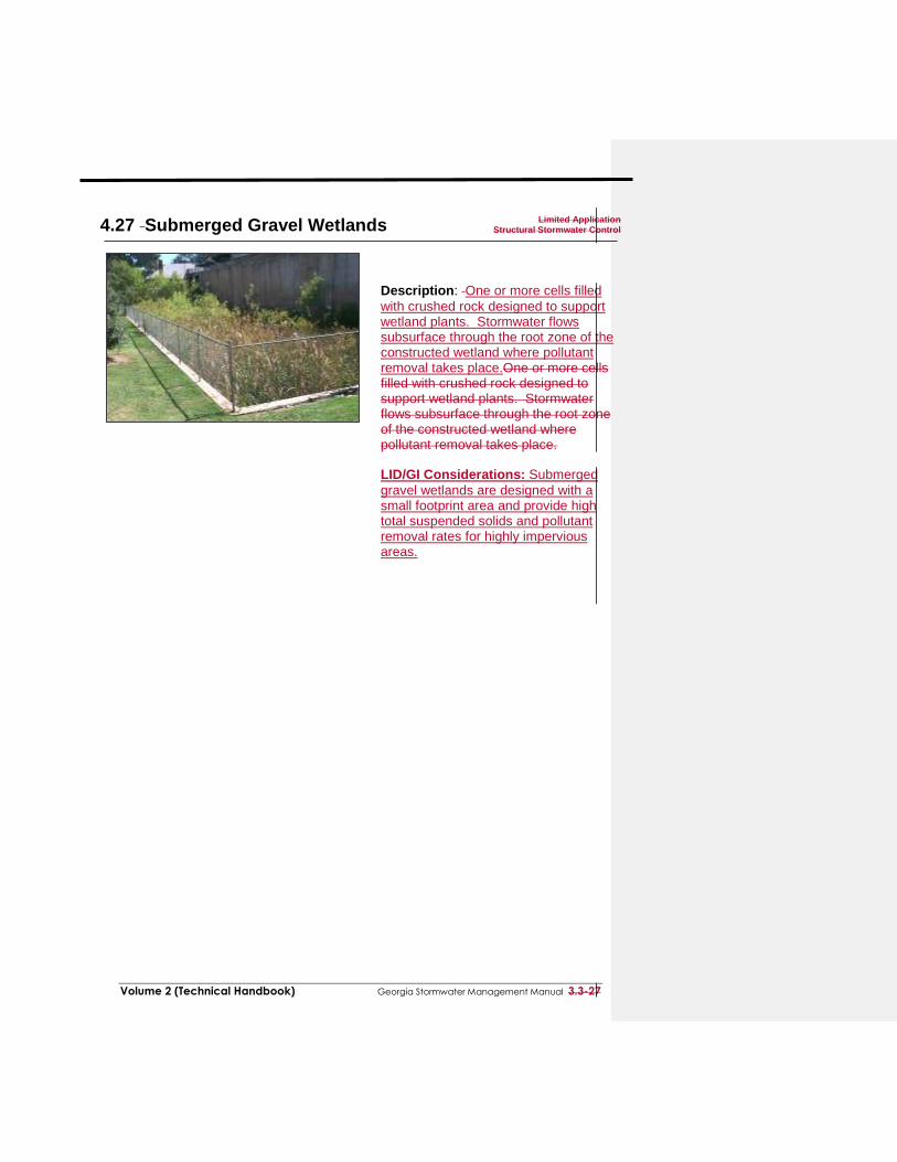
Volume 2 (Technical Handbook) Georgia Stormwater Management Manual 3.3-27 4.27 Submerged Gravel Wetlands Limited Application Structural Stormwater Control Description: One or more cells filled with crushed rock designed to support wetland plants. Stormwater flows subsurface through the root zone of the constructed wetland where pollutant removal takes place.One or more cells filled with crushed rock designed to support wetland plants. Stormwater flows subsurface through the root zone of the constructed wetland where pollutant removal takes place. LID/GI Considerations: Submerged gravel wetlands are designed with a small footprint area and provide high total suspended solids and pollutant removal rates for highly impervious areas.
with crushed rock designed to support wetland plants. Stormwater flows subsurface through the root zone of the constructed wetland where pollutant removal takes place.One or more cells filled with crushed rock designed to support wetland plants. Stormwater flows subsurface through the root zone of the constructed wetland where pollutant removal takes place. LID/GI Considerations: Submerged
gravel wetlands are designed with a small footprint area and provide high total suspended solids and pollutant removal rates for highly impervious areas.
Submerged gravel wetlands should be designed as off-line systems designed to handle only water quality volume.
Submerged gravel wetland systems need sufficient drainage area to maintain vegetation
The local slope should be relatively flat (<2%).
Elevation drop from the inlet to the outlet is required to ensure that hydraulic conveyance by gravity is feasible (generally about 3 to 5 feet).
All submerged gravel wetland designs should include a sediment forebay or other equivalent pretreatment measures to prevent sediment or debris from entering and clogging the gravel bed.
Unless they receive hotspot runoff, submerged gravel wetland systems can be allowed to intersect the groundwater table.
ADVANTAGES / BENEFITS:
High total suspended solids removal
High removal rate of urban pollutants
Useful in space-limited applications
Can be located in low-permeability soils with a high water table
DISADVANTAGES / LIMITATIONS:
High maintenance requirements
Drainage through the wetland can be problematic for low relief terrain
ROUTINE MAINTENANCE REQUIREMENTS: Ensure that inlets and outlets to each submerged gravel
wetland cell are free from debris and not clogged
Check for sediment buildup in gravel bed
If sediment buildup is preventing flow through the wetland, remove gravel and sediment from cell. Replace with clean gravel and replant vegetation.
POLLUTANT REMOVAL
Total Suspended Solids
Nutrients - Total Phosphorus / Total Nitrogen removal
Metals - Cadmium, Copper, Lead, and Zinc removal
Pathogens – Fecal Coliform
REASONS FOR LIMITED USE
Intended for space-limited applications High maintenance requirements
KEY CONSIDERATIONS
Generally requires low land consumption, and can fit within an area that is typically devoted to landscaping
High pollutant removal capabilities are expected; however, limited performance data exist
Can be located in low-permeability soils with a high water table
Periodic sediment removal required to prevent clogging of
STORMWATER MANAGEMENT
SUITABILITY
Runoff Reduction
Water Quality
Channel/Flood Protection
Overbank Flood Protection
Extreme Flood Protection
= suitable for this practice
= may provide partial benefits
IMPLEMENTATION
CONSIDERATIONS
L Land Requirement
H Capital Cost
M Maintenance Burden
Residential Subdivision Use: Yes
High Density/Ultra-Urban: Yes
Roadway Projects: No Soils: The HSG should be C or D,
or a high groundwater table, hard pan, or other confining layer should be present to maintain submerged flow conditions.
Other Considerations: Additional
space is needed for pretreatment measures to prevent sediment or debris from entering and clogging the gravel bed.
L=Low M=Moderate H=High
Runoff Reduction Credit: Runoff Reduction is not provided by a submerged gravel wetland. A pretreatment BMP or downstream regional facility should be used if runoff reduction is desired.
SPECIAL APPLICATIONS
Pretreatment
High Density/Ultra-Urban
Other: Hotspot areas
Residential Subdivision Use: No
510%23
0%%
860%
N/A70%
50%
Formatted: Font: Century Gothic
Formatted: Indent: Left: 0.5", No bullets or numbering
Formatted: No bullets or numbering, Adjust space betweenLatin and Asian text, Adjust space between Asian text andnumbers
Formatted: Indent: Left: 0.5", No bullets or numbering
Formatted: Font: 10 pt, Bold, No underline, Not All caps
Formatted: Left, Indent: Left: 0.69"
Formatted: Font: 10 pt, Not Bold, No underline, Not All caps
Formatted: Indent: Left: 0.13", Hanging: 0.19", Bulleted +Level: 1 + Aligned at: 0" + Tab after: 0.25" + Indent at: 0.25", Tab stops: 0.31", List tab + Not at 0.25"
Formatted: Indent: Left: 0.13", Hanging: 0.19", Bulleted +Level: 1 + Aligned at: 0" + Tab after: 0.25" + Indent at: 0.25", Tab stops: 0.31", List tab + Not at 0.25"
Formatted: Indent: Left: 0.13", Hanging: 0.19", Bulleted +Level: 1 + Aligned at: 0" + Tab after: 0.25" + Indent at: 0.25", Tab stops: 0.31", List tab + Not at 0.25"
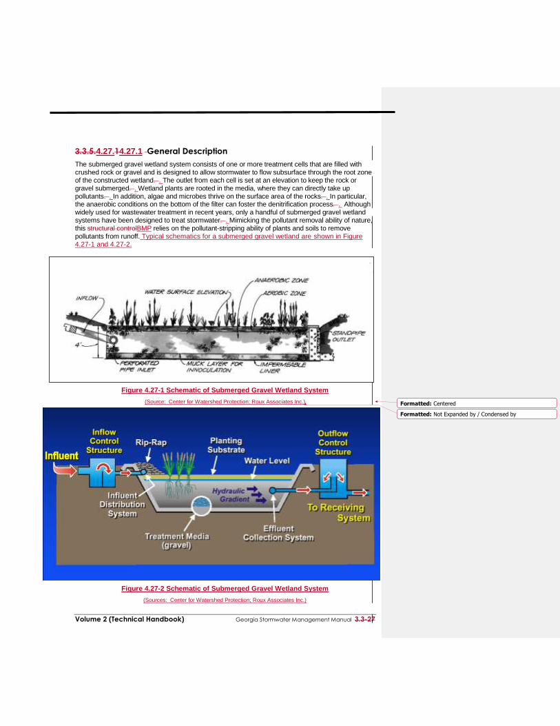
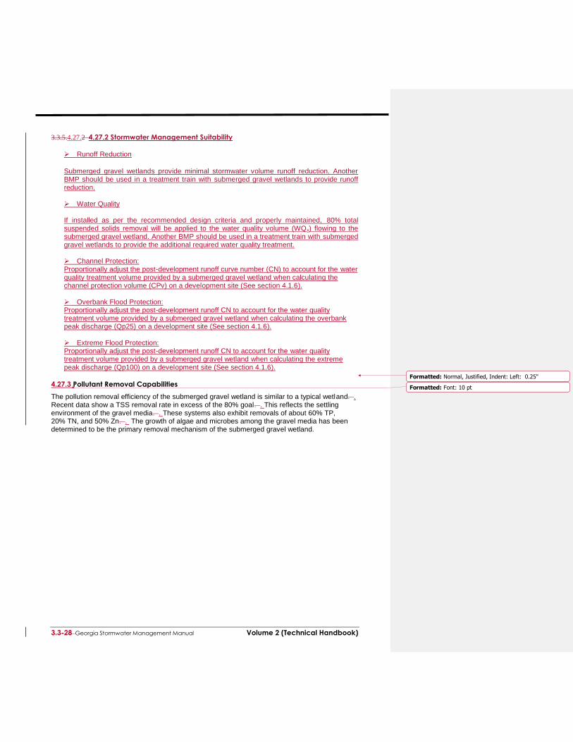
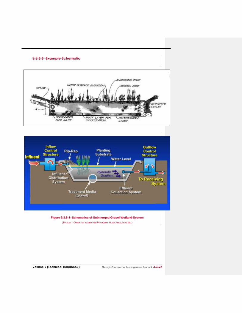
The submerged gravel wetland system consists of one or more treatment cells that are filled with crushed rock or gravel and is designed to allow stormwater to flow subsurface through the root zone of the constructed wetland. . The outlet from each cell is set at an elevation to keep the rock or gravel submerged. . Wetland plants are rooted in the media, where they can directly take up pollutants. . In addition, algae and microbes thrive on the surface area of the rocks. . In particular, the anaerobic conditions on the bottom of the filter can foster the denitrification process. . Although widely used for wastewater treatment in recent years, only a handful of submerged gravel wetland systems have been designed to treat stormwater. . Mimicking the pollutant removal ability of nature, this structural controlBMP relies on the pollutant-stripping ability of plants and soils to remove pollutants from runoff. Typical schematics for a submerged gravel wetland are shown in Figure 4.27-1 and 4.27-2.
Figure 4.27-1 Schematic of Submerged Gravel Wetland System
(Source: Center for Watershed Protection; Roux Associates Inc.)
Figure 4.27-2 Schematic of Submerged Gravel Wetland System
(Sources: Center for Watershed Protection; Roux Associates Inc.)
Submerged gravel wetlands provide minimal stormwater volume runoff reduction. Another BMP should be used in a treatment train with submerged gravel wetlands to provide runoff reduction.
Water Quality If installed as per the recommended design criteria and properly maintained, 80% total suspended solids removal will be applied to the water quality volume (WQv) flowing to the submerged gravel wetland. Another BMP should be used in a treatment train with submerged gravel wetlands to provide the additional required water quality treatment. Channel Protection: Proportionally adjust the post-development runoff curve number (CN) to account for the water quality treatment volume provided by a submerged gravel wetland when calculating the channel protection volume (CPv) on a development site (See section 4.1.6).
Overbank Flood Protection: Proportionally adjust the post-development runoff CN to account for the water quality treatment volume provided by a submerged gravel wetland when calculating the overbank peak discharge (Qp25) on a development site (See section 4.1.6).
Extreme Flood Protection: Proportionally adjust the post-development runoff CN to account for the water quality treatment volume provided by a submerged gravel wetland when calculating the extreme peak discharge (Qp100) on a development site (See section 4.1.6).
4.27.3 Pollutant Removal Capabilities
The pollution removal efficiency of the submerged gravel wetland is similar to a typical wetland. . Recent data show a TSS removal rate in excess of the 80% goal. . This reflects the settling environment of the gravel media. . These systems also exhibit removals of about 60% TP, 20% TN, and 50% Zn. . The growth of algae and microbes among the gravel media has been determined to be the primary removal mechanism of the submerged gravel wetland.
The following design pollutant removal rates are conservative average pollutant reduction percentages for design purposes derived from sampling data, modeling and professional judgment.
Total Suspended Solids – 80%
Total Phosphorus – 50%
Total Nitrogen – 20%
Fecal Coliform – 70%
Heavy Metals – 50%
4.27.4 Application and Site Feasibility Criteria A submerged gravel wetland is a small-scale filter using wetland plants in a rock media to provide water quality treatment. Runoff drains into the lowest elevation of the wetland, is distributed throughout the system, and discharges at the surface. Pollutant removal is achieved in a submerged gravel wetland through biological uptake from algae and bacteria growing within the filter media. Wetland plants provide additional nutrient uptake and physical and chemical treatment processes allow filtering and absorption of organic matter. The following criteria should be evaluated to ensure the suitability of submerged gravel wetlands for meeting stormwater management objectives on a site or development. General Feasibility
Suitable for Residential Subdivision Usage – YES
Suitable for High Density/Ultra Urban Areas – YES
Regional Stormwater Control – NO Physical Feasibility - Physical Constraints at Project Site
Drainage Area – In general, submerged gravel wetlands should be used on sites with a minimum area of 1 acre to ensure submerged flow conditions. The maximum drainage to a submerged gravel wetland is 5 acres.
Space Required – Additional space is needed for pretreatment measures to prevent sediment or debris from entering and clogging the gravel bed.
Site Slope – The local slope should be relatively flat (<2%). While there is no minimum slope requirement, there does need to be enough elevation drop from the inlet to the outlet to ensure that hydraulic conveyance by gravity is feasible (generally about 3 to 5 feet).
Minimum Depth to Water Table - Unless they receive hotspot runoff, submerged gravel wetland systems can be allowed to intersect the groundwater table. If a submerged gravel wetland receives hotspot runoff and has an underlying water supply aquifer, a separation distance of 2 feet is required between the bottom of the gravel and the elevation of the seasonally high water table to prevent groundwater contamination.
Soils – Submerged gravel wetlands can be used in almost all soils and geology, with minor design adjustments for regions of karst (i.e., limestone) topography or in rapidly percolating soils such as sand. In these areas, submerged gravel wetlands should be designed with an impermeable liner to prevent groundwater contamination or sinkhole formation.
Other Constraints / Considerations
Hot spots – Submerged gravel wetlands without a liner should not be used to treat hotspots that generate higher concentrations of hydrocarbons, trace metals, or toxicants than are found in typical stormwater runoff and may contaminate groundwater.
Proximity – The following is a list of specific setback requirements for the location of a submerged gravel wetlands area:
10 feet from building foundations
10 feet from property lines
100 feet from private water supply wells
100 feet from open water (measured from edge of water)
200 feet from public water supply reservoirs (measured from edge of water)
Trout Stream –In cold water streams, submerged gravel wetlands should be designed to detain stormwater for a relatively short time (i.e., less than twelve hours) to minimize the potential amount of stream warming that occurs in the practice.
Coastal Areas
Poorly Drained Soils, such as hydrologic soil groups C and D— Since they are equipped with waterproof liners, the presence of poorly drained soils does not influence the use of submerged gravel wetlands on development sites.
Well drained soils, such as hydrologic soil group A and B - Since they are equipped with waterproof liners, the presence of well drained soils does not influence the use of submerged gravel wetlands on development sites.
Flat Terrain - The presence of flat terrain does not preclude the use of a submerged gravel
wetland.
Shallow Water Table – Except in the case of hotspot runoff, the base of the submerged gravel wetland can intersect the ground water table.
Tidally-influenced drainage system – Saltwater intrusion of the submerged gravel wetland should not be allowed.
4.27.5 Planning and Design Criteria
3.3.5.4.27.3 Design Criteria and Specifications
Before designing the submerged gravel wetland, the following data is necessary:
Existing and proposed site, topographic and location maps, and field reviews.
Impervious and pervious areas. Other means may be used to determine the land use data.
Roadway and drainage profiles, cross sections, utility plans, and soil report for the site.
Design data from nearby storm sewer structure.
Water surface elevation of nearby water systems as well as the depth to seasonally high groundwater.
The following criteria are to be considered minimum standards for the design of a submerged gravel wetland. Consult with the local review authority to determine if there are any variations to these criteria or additional standards that must be followed.
4.27.5.1 Location and Layout
Submerged gravel wetlands are generally applied to land uses with a high percentage of impervious surfaces. Submerged gravel wetlands should be located upstream or downstream of other BMPs providing runoff reduction, channel protection volume (CPv), overbank flood protection (QP25) and extreme flood protection (Qf). See Section 4.1.6 for more information on the use of multiple BMPs in a treatment train.
4.27.5.2 General Design
Pretreated stormwater enters via piped or overland flow and discharges into the gravel-filled chamber. A perforated pipe (4 to 6-inch preferred) at the base of the gravel layer allows for flow-through conditions and maintains a constant water surface elevation. Discharges that exceed the WQv exit to a stable outfall at non-erosive velocities.
4.27.5.3 Physical Specifications / Geometry
The aggregate shall be composed of an 18 to 48 inch layer of clean washed, uniformly graded material with a porosity of 40%. Rounded bank run gravel is recommended (e.g., ASTM D448 4,5, or 6 stone or equal).
Storage for the WQv for the entire drainage area contributing to the wetland shall be provided. Temporary ponding depth shall not be greater than the tolerance levels of the
Formatted: Body Text, Indent: Left: 0", Widow/Orphancontrol, Tab stops: 0.25", Left + Not at 0.36" + 0.7" + 1.18" + 3.5" + 6.9"
Formatted: Font: Bold, Underline
Formatted: Underline
Formatted: Underline
Formatted: Underline
Formatted: Underline
Formatted: Font: Bold, Underline
Formatted: Font: Bold
Formatted: Font: Bold
Formatted: Body Text, Indent: Left: 0", Tab stops: 0.25",Left
Formatted: Font: Bold
Formatted: Indent: Left: 0"
Formatted: Indent: Left: 0", Tab stops: 0.25", List tab +Not at 0.5"
Formatted: Normal, Don't adjust space between Latin andAsian text, Don't adjust space between Asian text andnumbers
Formatted: Indent: Left: 0"
Formatted: Font: Arial
Formatted: Normal, Indent: Left: 0", Bulleted + Level: 1 +Aligned at: 0.25" + Indent at: 0.5", No widow/orphancontrol, Tab stops: 0.25", List tab + 0.36", Left + 0.7", Left+ 1.18", Left + 3.5", Left + 6.9", Left
Formatted: Font: Arial, Not Superscript/ Subscript
wetland vegetation. Temporary storage of WQv may be provided above the gravel bed.
Storage calculations shall account for the porosity of the gravel media.
The gravel substrate shall be no deeper than four feet.
Flow Splitter: A flow splitter should be provided to divert the WQv to the submerged gravel wetland.
Multiple treatment cells are optional and may be separated by earth berms.
An observation well consisting of an anchored, six-inch diameter perforated pipe shall be required. The top of the observation well shall be at least six inches above grade.
A minimum 20’ wide maintenance right-of-way or drainage easement shall be provided to a submerged gravel wetland from a driveway, public or private road. The maintenance access easement shall have a maximum slope of no more than 15% and shall have a minimum unobstructed drive path having a width of 12 feet, appropriately stabilized to withstand maintenance equipment and vehicles.
4.27.5.4 Pretreatment \ Inlets
Sediment regulation and removal is critical to sustain submerged gravel wetlands.
A gravel wetland facility shall have a sediment forebay or equivalent upstream pretreatment.
A sediment forebay is designed to remove incoming sediment from the stormwater flow prior to dispersal into the wetland.
The forebay shall consist of a separate cell, formed by an acceptable barrier. A forebay shall be provided at each inlet, unless the inlet provides less than 10% of the total design storm inflow to the gravel wetland facility.
The forebay shall be sized to contain 0.1 inches per impervious acre of contributing drainage and shall be no more than 4 feet deep. The pretreatment storage volume is part of the total WQv design requirement and may be subtracted from the WQv for wetland storage sizing. A fixed vertical sediment depth marker shall be installed in the forebay to measure sediment deposition over time.
4.27.5.5 Outlet Structures
For a submerged gravel wetland, the outlet structure can consist of a weir, orifice, outlet pipe, combination outlet, or other acceptable control structure.
Small outlets that will be subject to clogging or are difficult to maintain are not acceptable.
4.27.5.6 Safety Features
A minimum of 6 inches of freeboard must be provided, measured from the top of the water surface elevation for the water quality volume, to the lowest point of the ground surface elevation, not counting the outlet weir.
Stormwater should be conveyed to and from submerged gravel wetlands safely and to minimize erosion potential.
4.27.5.7 Landscaping
Use of native wetland plant stock obtained from a local aquatic plant nursery is recommended for establishing vegetation.
A minimum of three different types of wetland species shall be provided.
Design variations may use wetland mulch or topsoil on top of the gravel, which may allow for successful seed germination.
Use of the rock media for establishing wetland conditions requires specific planting stock.
Frequent inspection and maintenance will be necessary until wetland plantings are well established.
Replacement plantings may be necessary.
4.27.5.8 Construction Considerations
Construction equipment should be restricted from the submerged gravel wetland to prevent compaction of the native soils.
All on-site disturbed areas should be stabilized prior to allowing runoff to enter the newly
Formatted: Font: Arial, Not Superscript/ Subscript
Formatted: Font: Arial
Formatted: Font: Arial
Commented [JLS4]: MD SWM Manual
Formatted: Font: Arial
Commented [JLS5]: Knox County
Formatted: Font: Arial
Commented [JLS6]: Knox County
Formatted: Indent: Left: 0", Tab stops: 0.25", List tab
The proposed location of a submerged gravel wetland shall be protected during construction. Surface runoff shall be diverted away from the practice during grading operations. Flow splitters and other conveyance infrastructure shall be blocked.
Wetland construction shall be performed with lightweight, wide-tracked equipment to minimize disturbance and compaction. Excavated materials shall be placed in a contained area. Any pumping operations shall discharge filtered water to a stable outlet.
4.27.5.8 Construction and Maintenance Costs
A rough rule of thumb estimate for submerged gravel wetland construction costs is approximately $4 - $5/square foot, including sediment forebay
4.27.6 Design Procedures
In general, site designers should perform the following design procedures when designing a submerged gravel wetland.
Step 1. Determine the goals and primary functions of the submerged gravel wetland
A submerged gravel wetland can be designed to provide treatment of the water quality volume (WQv),
Check with local officials and other agencies to determine if there are any additional restrictions and/or surface water or watershed requirements that may apply. In addition, consider if the submerged gravel wetland has any special site-specific design conditions or criteria. List any restrictions or other requirements that may apply or affect the design.
Step 2. Determine if the development site and conditions are appropriate for the use of a submerged gravel wetland
Consider the application and site feasibility criteria in this chapter. In addition, determine if site conditions are suitable for a submerged gravel wetland. Create a rough layout of the submerged gravel wetland dimensions taking into consideration existing trees, utility lines, and other obstructions. Step 3. Determine submerged gravel wetland location and preliminary geometry This step involves initially designing the grading of the wetland (establishing contours) and determining the elevation-storage relationship for the wetland. Include sediment forebay and outfall weir. Step 4. Calculate the Target Water Quality Volume
Calculate the Target Water Quality Volume using the following formula: WQv = (1.2) (RV) (A) / 12 Where: WQv = Target Water Quality Volume (cubic-feet) 1.2 = Target rainfall amount to be treated (inches) Rv = Volumetric runoff coefficient which can be found by: RV = 0.05+0.009(I) Where: I = new impervious area of the contributing drainage area (%) A = Site area (square feet) 12 = Unit conversion factor (in/ft)
Step 5. Calculate the Water Quality volume (WQv) provided by the submerged gravel wetland:
To determine the storage provided in the submerged gravel wetland, use the following equation: VP = (PV + VGM (N))
Commented [JLS8]: MD SWM Manual
Formatted: Font: Bold
Formatted: Font: Arial
Formatted: Normal, Space After: 0 pt, No bullets ornumbering, No widow/orphan control, Tab stops: 0.36", Left+ 0.7", Left + 1.18", Left + 3.5", Left + 6.9", Left
Formatted: Font: Arial
Commented [JLS9]: Charles River Watershed Association
Where: VP = Volume provided (temporary storage) PV = Ponding Volume VGM = Volume of Gravel Media N = Porosity Using Table 4.1.3-2 - BMP Runoff Reduction Credits, lookup the appropriate runoff WQv/TSS removal provided by the practice: Calculate the Water Quality Volume/TSS Removal provided by the selected practice WQv (provided) = (WQv/TSS%) (VP) Where: WQv (provided) = Water Quality Volume/Total Suspended Solids Removal provided (cubic feet) by a specific BMP WQv/TSS% = Water Quality Volume/Total Suspended Solids Removal percentage, or credit, assigned to the specific practice VP = As calculated above When WQv (provided) = Target WQv, Water Quality requirements are met. If WQv (provided) is less than the Target WQv, then additional water quality treatment/TSS removal or runoff reduction volume must be provided by an upstream or downstream BMP
Step 6. Size flow diversion structure, if needed
If the contributing drainage area to the submerged gravel wetland exceeds the water quality treatment and/or storage capacity, flow regulator (or flow splitter diversion structure) should be supplied to divert the WQv (or RRv) to the submerged gravel wetland.
Step 7. Design stable outfall
An overflow, such as an overdrain with an invert set slightly above the elevation of maximum ponding depth, must be provided to bypass and/or convey larger flows to the downstream drainage system or stabilized watercourse. Non-erosive velocities need to be ensured at the outlet point. The overflow should be sized to safely pass the peak flows anticipated to reach the practice.
Step 8. Prepare Vegetation and Landscaping Plan
A landscaping plan for the submerged gravel wetland should be prepared to indicate how it will be established with vegetation. See section 4.27.5.7 (Landscaping) and Appendix D for more details.
Submerged gravel wetlands should be designed as off-line systems designed to handle only water quality volume.
Submerged gravel wetland systems need sufficient drainage area to maintain vegetation.
See subsection 2.1.8 for guidance on performing a water balance calculation. The local slope should be relatively flat (<2%). While there is no minimum slope requirement,
there does need to be enough elevation drop from the inlet to the outlet to ensure that hydraulic conveyance by gravity is feasible (generally about 3 to 5 feet).
All submerged gravel wetland designs should include a sediment forebay or other equivalent
pretreatment measures to prevent sediment or debris from entering and clogging the gravel bed.
Unless they receive hotspot runoff, submerged gravel wetland systems can be allowed to
intersect the groundwater table. Guidance on establishing wetland vegetation can be found in Appendix F, Landscaping and Aesthetics Guidance.
Formatted: Body Text, Indent: Left: 0.36", Adjust spacebetween Latin and Asian text, Adjust space between Asiantext and numbers, Pattern: 12.5% (Auto Foreground, WhiteBackground)
Formatted: Font: (Default) Arial
Formatted: Normal, Indent: Left: 0.36", No widow/orphancontrol, Pattern: 12.5% (Auto Foreground, WhiteBackground), Tab stops: 0.36", Left + 0.7", Left + 1.18",Left + 3.5", Left + 6.9", Left
See subsection 3.2.2 (Stormwater Wetlands) for additional planning and design guidance.
3.3.5.4.27.4 Inspection and Maintenance Requirements
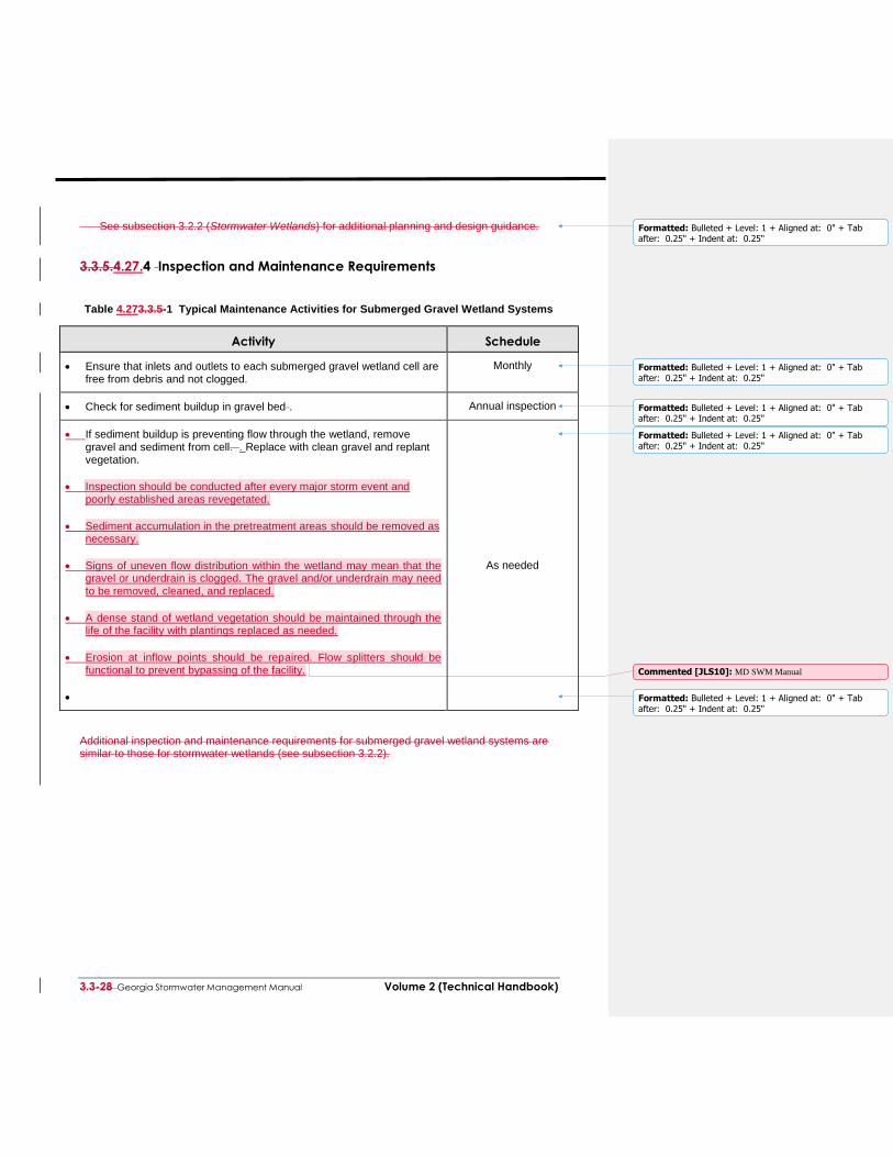
Table 4.273.3.5-1 Typical Maintenance Activities for Submerged Gravel Wetland Systems
Activity
Schedule
Ensure that inlets and outlets to each submerged gravel wetland cell are free from debris and not clogged.
Monthly
Check for sediment buildup in gravel bed . Annual inspection
If sediment buildup is preventing flow through the wetland, remove gravel and sediment from cell. . Replace with clean gravel and replant vegetation.
Inspection should be conducted after every major storm event and poorly established areas revegetated.
Sediment accumulation in the pretreatment areas should be removed as necessary.
Signs of uneven flow distribution within the wetland may mean that the gravel or underdrain is clogged. The gravel and/or underdrain may need to be removed, cleaned, and replaced.
A dense stand of wetland vegetation should be maintained through the life of the facility with plantings replaced as needed.
Erosion at inflow points should be repaired. Flow splitters should be functional to prevent bypassing of the facility.
As needed
Additional inspection and maintenance requirements for submerged gravel wetland systems are similar to those for stormwater wetlands (see subsection 3.2.2).