20
430BOOST-SENSE1 – Capacitive Touch BoosterPack for the LaunchPad User's Guide Literature Number: SLAU337 March 2011
430BOOST-SENSE1 – Capacitive TouchBoosterPack for the LaunchPad
User's Guide
Literature Number: SLAU337
March 2011

2 SLAU337–March 2011Submit Documentation Feedback
© 2011, Texas Instruments Incorporated
Preface ....................................................................................................................................... 51 430BOOST-SENSE1 Overview .............................................................................................. 6
1.1 Overview .................................................................................................................. 6
1.2 Kit Contents .............................................................................................................. 7
2 Getting Started with 430BOOST-SENSE1 BoosterPack ............................................................ 72.1 Hardware Preparation .................................................................................................. 7
2.2 Software Preparation ................................................................................................... 8
2.3 Capacitive Touch User Experience ................................................................................... 8
3 The Capacitive Touch BoosterPack Hardware ....................................................................... 113.1 Driving the LEDs ....................................................................................................... 13
3.2 Capacitive Touch sensors ............................................................................................ 14
4 LaunchPad Capacitive Touch BoosterPack User Experience Firmware .................................... 154.1 Project Import in CCS ................................................................................................. 15
4.2 Open project & workspace with IAR embedded workbench ..................................................... 15
4.3 Capacitive Touch Library ............................................................................................. 15
5 LaunchPad Capacitive Touch BoosterPack User Experience Software .................................... 175.1 LaunchPad Capacitive Touch BoosterPack User Experience GUI ............................................. 17
5.2 MediaPad ............................................................................................................... 17
5.3 UART Communication Protocol ...................................................................................... 17
6 Frequently Asked Questions (FAQ), Tips & Tricks ................................................................. 187 Reference ......................................................................................................................... 188 Appendix .......................................................................................................................... 19
8.1 Schematics ............................................................................................................. 19
8.2 PCB Layout ............................................................................................................. 20
8.3 Bill of Materials (BOM) ................................................................................................ 20
3SLAU337–March 2011 Table of ContentsSubmit Documentation Feedback
© 2011, Texas Instruments Incorporated

www.ti.com
List of Figures
1 Capacitive Sense BoosterPack with LaunchPad ....................................................................... 7
2 PC GUI is looking for LaunchPad......................................................................................... 9
3 PC GUI in sleep mode .................................................................................................... 10
4 PC GUI in active mode ................................................................................................... 10
5 MediaPad ................................................................................................................... 11
6 Capacitive Sense BoosterPack HW .................................................................................... 12
7 Schematic LED multiplexing ............................................................................................. 13
8 LED driving ................................................................................................................. 14
9 Capacitive Touch sensor areas.......................................................................................... 14
10 Capacitive Touch BoosterPack schematics............................................................................ 19
11 Capacitive Touch BoosterPack layout top layer....................................................................... 20
12 Capacitive Touch BoosterPack layout bottom layer and silkscreen ................................................ 20
List of Tables
1 BoosterPack Interface .................................................................................................... 12
2 Bill of Materials............................................................................................................. 20
4 List of Figures SLAU337–March 2011Submit Documentation Feedback
© 2011, Texas Instruments Incorporated

PrefaceSLAU337–March 2011
Read This First
If You Need Assistance
If you have any feedback or questions, support for the MSP430 device, the MSP-EXP430G2 LaunchPadand the 430BOOST-SENSE1 BoosterPack for the LaunchPad is provided by the Texas InstrumentsProduct Information Center (PIC) and the TI E2E Forum (https://community.ti.com/forums/12.aspx).Contact information for the PIC can be found on the TI web site at support.ti.com. Additionaldevice-specific information can be found on the MSP430 web site at www.ti.com/msp430.
Related Documentation from Texas Instruments
The primary sources of MSP430 information are the device-specific data sheets and user's guides. Themost up-to-date versions of the user's guide documents available at www.ti.com/msp430 Informationspecific to the MSP-EXP430G2 LaunchPad Experimenter Board and the different BoosterPacks can befound at http://focus.ti.com/docs/toolsw/folders/print/msp-exp430g2.html or the LaunchPad wiki page athttp://processors.wiki.ti.com/index.php/MSP430_LaunchPad_(MSP-EXP430G2.
User's guides and detailed information on setting up a project for the MSP430 using Code ComposerStudio or IAR Embedded Workbench can be found at the Tools & Software section of the MSP430 landingpage.www.ti.com/msp430
FCC Warning
This equipment is intended for use in a laboratory test environment only. It generates, uses, and canradiate radio frequency energy and has not been tested for compliance with the limits of computingdevices pursuant to subpart J of part 15 of FCC rules, which are designed to provide reasonableprotection against radio frequency interference. Operation of this equipment in other environments maycause interference with radio communications, in which case, the user will be required to take whatevermeasures may be required to correct this interference his own expense.
5SLAU337–March 2011 PrefaceSubmit Documentation Feedback
© 2011, Texas Instruments Incorporated

User's GuideSLAU337–March 2011
430BOOST-SENSE1 - Capacitive Touch BoosterPack forthe LaunchPad
1 430BOOST-SENSE1 Overview
1.1 Overview
The 430BOOST-SENSE1 is the first extension module for the MSP-EXP430G2 LaunchPad. Theseextension modules, designed specifically for the LaunchPad, are called BoosterPacks and each featuresan application example for one of the MSP430 ValueLine devices. The BoosterPacks can be connected tothe MSP-EXP430G2 with both 10 pin male headers (included in MSP-EXP430G2 kit) soldered onto theboard and therefore use all available pins on the MSP430G2452 ValueLine device.
This Capacitive Sense BoosterPack is designed to feature the new MSP430G2xx2 devices which arecapable of driving up to 16 touch-sense enabled I/O pins. The included MSP430G2452 device allows forlow cost capacitive sense and approximation sensing applications without the use of any externalcomponents. The BoosterPack includes a Capacitive Sense Board and an MSP420G2452 devicepreprogrammed with a demo application. The user experience application demonstrates Capacitive Senseas standalone feature by showing the user interaction directly with the onboard LEDs, by a GUI or anapplication example on a Microsoft Windows PC.
430BOOST-SENSE1 features:
• 9 LEDs giving instant feedback to user interaction• 6 touch-sense areas (a button, a 4-element wheel and a proximity sensor)• 1 preprogrammed MSP430G2452 device
6 430BOOST-SENSE1 - Capacitive Touch BoosterPack for the LaunchPad SLAU337–March 2011Submit Documentation Feedback
© 2011, Texas Instruments Incorporated

www.ti.com Getting Started with 430BOOST-SENSE1 BoosterPack
Figure 1. Capacitive Sense BoosterPack with LaunchPad
For latest information on the LaunchPad, other available BoosterPacks, software examples and how toprogram the included MSP430G2452 device take a look at the MSP-EXP430G2 User’s Guide (SLAU318)or the LaunchPad wiki pagehttp://processors.wiki.ti.com/index.php/MSP430_LaunchPad_(MSP-EXP430G2).
1.2 Kit Contents
The 430BOOST-SENSE1 kit includes two components:
• The Capacitive Touch BoosterPack Board with 9 LEDs and 6 sensor areas• A preprogrammed MSP430G2452 device
– o Low-power 16Bit microcontroller with an 8-channel 10-bit ADC, Comparator, Universal SerialInterface supporting SPI and I2C, 8kB FLASH and 256B RAM memory
2 Getting Started with 430BOOST-SENSE1 BoosterPack
There are different preparations required to get the user experience application demo to work correctlyand to start developing applications with the MSP430G2452 for the Capacitive Touch BoosterPack.
2.1 Hardware Preparation
Follow the described steps properly to ensure proper device operation.
1. Solder both 10-pin male headers on to the LaunchPad's breakout pin connections J1 and J2. Thesetwo 10-pin male headers as well as two 10-pin female headers come with the original LaunchPad kit.Note: If the 10-pin female headers are already populated, simply use the 10-pin male headers asadapter to further extend the connections to the LaunchPad. The additional distance adds minimalbase capacitance and does not affect the user experience of the kit.
2. Remove J5 connections to disconnect the LaunchPad LEDs and keep them from interfering with P1.0& P1.6 functions of the Capacitive Sense BoosterPack.
3. Ensure jumpers VCC, TXD, & RXD of J3 connection are populated in order for the user experience
7SLAU337–March 2011 430BOOST-SENSE1 - Capacitive Touch BoosterPack for the LaunchPadSubmit Documentation Feedback
© 2011, Texas Instruments Incorporated

Getting Started with 430BOOST-SENSE1 BoosterPack www.ti.com
demo to operate properly.Note: The Jumpers RST & TEST must also be populated when programming the device. They are notrequired for normal demo application operation.
4. Replace the existing MSP430 device in the LaunchPad MCU socket with the MSP430G2452 devicethat comes with the Capacitive Sense BoosterPack kit.
5. Plug the Capacitive Sense BoosterPack board in the LaunchPad with proper orientation by ensuringthat the Texas Instruments logo and the texts on the BoosterPack are in the same direction with thetexts and logo on the Launchpad.
6. Connect the LaunchPad with an USB cable to a PC or connect an external power supply (2.7V to3.6V) to J6, the user experience demo application will light up the Center LED as soon as power issupplied to the board.
NOTE: The 32-kHz crystal/oscillator on Pin 18 and 19 is not required for the application to work.
2.2 Software Preparation
This step is not required for a LaunchPad Capacitive Touch BoosterPack stand-alone demo. For all otherpurposes that require PC software interaction, proper installation of the hardware driver and the softwareis required. To develop applications its also necessary to install one of the IDEs shown on the Tools andSoftware section of the MSP430 landing page www.ti.com/msp430. More information on how to startdeveloping applications for the LaunchPad and how to install the drivers and IDEs required the
All software necessary to run the User Experience demo can be found in the LaunchPad CapacitiveTouch BoosterPack software package located on the LaunchPad wiki pagehttp://processors.wiki.ti.com/index.php/MSP430_LaunchPad_(MSP-EXP430G2)Once installed all UserExperience application demos are stores inside the Software folder within the selected installationdirectory.
2.2.1 LaunchPad USB Driver
In order for the PC to communicate to the hardware, the LaunchPad's USB driver must be installed. If thisis the first time the LaunchPad is connected to the PC, install the USB serial COM port driver located at[INSTALL_PATH]\LaunchPad_Driver\LaunchPad_Driver.exe.
NOTE: The LaunchPad USB Drivers is integrated into the IDE installer packages from CodeComposer Studio (version 4+) or IAR Embedded Workbench (version 5.20+) and do notrequire a second installation if an IDE has already been installed.
2.2.2 Locate Software Programs
Two software programs are provided to work with the LaunchPad Capacitive Touch BoosterPack UserExperience demo. They can be both located under [INSTALL_PATH]\Software. All software and firmwareexamples are also available as source code within the Capacitive Touch software package.
2.3 Capacitive Touch User Experience
The Capacitive Touch User Experience consists of three projects: the firmware application that canoperate in stand-alone mode [LaunchPad Capacitive Touch BoosterPack Firmware Demo], a processingGUI that displays the information from the LaunchPad Capacitive Touch BoosterPack visually[LaunchPadCapacitive Touch BoosterPack GUI Demo] and a Visual Studio program that uses the LaunchPadCapacitive Touch BoosterPack input to control media in Windows [MediaPad].
2.3.1 LaunchPad Capacitive Touch BoosterPack Firmware Demo
This part applies for both stand-alone demo (no PC required) and demo with PC applications running. IfPC application is desired, make sure to start the PC application execution before proceeding with step 2.
8 430BOOST-SENSE1 - Capacitive Touch BoosterPack for the LaunchPad SLAU337–March 2011Submit Documentation Feedback
© 2011, Texas Instruments Incorporated

www.ti.com Getting Started with 430BOOST-SENSE1 BoosterPack
1. Plug the LaunchPad with Capacitive Touch BoosterPack into a USB source (such as USB port on PC,USB Hub, USB battery pack, etc.) via the mini-USB connector or to a battery pack via the power pinconnector J6. The User Experience application starts up and remains in 'sleep' mode, with only thecenter LED on.
2. Slowly wave hand or finger ~3-5cm above the BoosterPack in order to trigger the proximity sensor andto wake up the device. During the wake up period, the LEDs surrounding the wheel light in a wake-upsequence, starting with a slow clockwise rotation and ending with a fast counter-clockwise rotation. Asthis sequence ends, the device enters active mode.
3. Firmly press any position on the wheel or the center button to perform a touch. Make sure to keepfinger fully and between the circles of the wheel.
• Upon releasing a touch on the center button, the center LED toggles.• Touching a wheel position lights up the corresponding LEDs.
4. Slide along the wheel without releasing finger from the wheel to perform a gesture. The correspondingLEDs trace & follow the touch & gesture.
5. After a period of no capacitive touch activity, the board returns to sleep mode. Only the center LEDstays on.
6. Go back to step 2 to re-enable the application active mode.
2.3.2 LaunchPad Capacitive Touch BoosterPack GUI Demo
This part describes instructions to run the application on both of the LaunchPad Capacitive TouchBoosterPack and the PC. Hence it assumes that the hardware is connected to the PC via USB cable[Step 1 of Section 2.3.1] and proper software installation [Section 2.2].
The steps described below also correspond to instructions described in Section 2.3.1.
1. Start the CapTouch_BoosterPack_UserExperience_GUI.exe application located at[INSTALL_PATH]\Software\CapTouch_BoosterPack_UserExperience_GUI\Upon startup, the GUI checks for a valid LaunchPad USB serial COM port. If no compatible portconnection is available, the GUI prompts user to plug in the LaunchPad Capacitive TouchBoosterPack. The GUI will continue as normal whenever a LaunchPad is plugged into the PC.
Figure 2. PC GUI is looking for LaunchPad
2. Upon start-up or after long period of inactivity, the device goes into sleep mode. The GUI grays outaccordingly to indicate such inactivity. Upon proximity sensor detection (wave hand ~3-5cm above theBoosterPack) the device returns to active mode and triggers the GUI to wake up as well.
9SLAU337–March 2011 430BOOST-SENSE1 - Capacitive Touch BoosterPack for the LaunchPadSubmit Documentation Feedback
© 2011, Texas Instruments Incorporated

Getting Started with 430BOOST-SENSE1 BoosterPack www.ti.com
Figure 3. PC GUI in sleep mode
3. The 'Center Button' press data toggles the center circle color, mimicking the behavior of the centerLED on the BoosterPack.The 'Wheel Tap' is represented by lighting up a single slice on the wheel and displaying the fieldnumber on the left upper corner of the PC GUI.
4. The gesture tracking [Start, Stop, Update] is visualized on the wheel with the coloration of the wheelslices. Gesture can be tracked for several revolutions of the wheel, in both clockwise andcounter-clockwise directions.
Figure 4. PC GUI in active mode
5. After a period of no capacitive touch activity, the board returns to sleep mode. The GUI also grays outand returns to 'sleep mode' as well.* Embedded within the wheel, a hidden mode can be unlocked. Correct sequence [similar to arotational combination lock] reveals a secret.
2.3.3 MediaPad
This part describes instructions to run the application on both of the LaunchPad Capacitive TouchBoosterPack and the PC. Hence it assumes that the hardware is connected to the PC via USB cable[Step 1 of 2.3.1] and proper software installation [Step 2.2].
Start the MediaPad.exe application located at [INSTALL_PATH]\Software\MediaPad\
10 430BOOST-SENSE1 - Capacitive Touch BoosterPack for the LaunchPad SLAU337–March 2011Submit Documentation Feedback
© 2011, Texas Instruments Incorporated

www.ti.com The Capacitive Touch BoosterPack Hardware
Upon execution, the application starts looking for a LaunchPad or an eZ430 emulator compatible USBserial COM port. If no compatible COM port is found, the application displays an error message whichthen exits the application. If a LaunchPad COM port is found, the application prompts a greeting start-upmessage. Once the message is closed, the application minimizes itself to the taskbar.
When the LaunchPad Capacitive Touch BoosterPack is in sleep mode, no data is transferred and noactivity occurs in the program. Use hand/finger wave motion to trigger the proximity sensor and wake upthe device.
The following touches or gestures can be used for media control in a Windows system.
1. Center button press: Start Media Player [Windows Media Player by default]**2. Bottom arrow button press: Play/Pause3. Left arrow button press: Previous Track4. Right arrow button press: Next Track5. Scroll wheel clockwise: Volume Up6. Scroll wheel counter-clockwise: Volume Down
Figure 5. MediaPad
Note: The Microsoft .NET runtime library might be required in order to execute the MediaPad software.While most recent Windows PC come pre-installed with .Net runtime library, a new/re- install of the librarymight be necessary.
3 The Capacitive Touch BoosterPack Hardware
The Capacitive Touch BoosterPack Board is showing a typical Capacitive Touch application example forthe new MSP430G2xx2 Touch-sense enabled I/O Pins. The board is showing three different capacitivesensor types, a single button right in the middle, a wheel made up from 4 single capacitive sensors and aproximity sensor all around the PCB. Additionally there are 9 LEDs on the Board to give instant feedbackto user interaction. The eight LEDs around the wheel are multiplexed to increase their number withoutusing too much of the microcontrollers I/O Pins. This way only 5 pins are use to drive all 8 LEDs by atimeshared signal.
11SLAU337–March 2011 430BOOST-SENSE1 - Capacitive Touch BoosterPack for the LaunchPadSubmit Documentation Feedback
© 2011, Texas Instruments Incorporated

The Capacitive Touch BoosterPack Hardware www.ti.com
Figure 6. Capacitive Sense BoosterPack HW
The Capacitive Touch BoosterPack Board is showing a typical Capacitive Touch application example forthe new MSP430G2xx2 Touch-sense enabled I/O Pins. The board is showing three different capacitivesensor types, a single button right in the middle, a wheel made up from 4 single capacitive sensors and aproximity sensor all around the PCB. On top of the PCB there is a 0.8mm thick layer of acrylic to insulatethe PCB like its used on most Capacitive Touch applications. Additionally there are 9 LEDs on the Boardto give instant feedback to user interaction. The eight LEDs around the wheel are multiplexed to increasetheir number without using too much of the microcontrollers I/O Pins. This way only 5 pins are use to driveall 8 LEDs by a timeshared signal.
Table 1. BoosterPack Interface
BoosterPackPin MSP430 Port DescriptionSignal
1 VCC NC Supply voltage, not Connected to BoosterPack
2 P1.0 LED9 The white center LED
Backchannel UART transmit data output, not connected3 P1.1/TXD NC to BoosterPack
Backchannel UART receive data input, not connected to4 P1.2/RXD NC BoosterPack
5 P1.3 LEDx LED base to drive the 8 multiplexed LEDs
6 P1.4 LED1 LED1 positive LED5 negative drive
7 P1.5 LED2 LED2 positive LED6 negative drive
8 P2.0 SENS0 Touch-sense proximity sensor
9 P2.1 SENS1 Touch-sense wheel sensor left
10 P2.2 SENS2 Touch-sense wheel sensor down
11 P2.3 SENS3 Touch-sense wheel sensor right
12 P2.4 SENS4 Touch-sense wheel sensor up
13 P2.5 SENS5 Touch-sense center button sensor
14 P1.6 LED3 LED3 positive LED7 negative drive
15 P1.7 LED4 LED4 positive LED8 negative drive
12 430BOOST-SENSE1 - Capacitive Touch BoosterPack for the LaunchPad SLAU337–March 2011Submit Documentation Feedback
© 2011, Texas Instruments Incorporated
www.ti.com The Capacitive Touch BoosterPack Hardware
Table 1. BoosterPack Interface (continued)
BoosterPackPin MSP430 Port DescriptionSignal
Reset line for SBW JTAG data, not connected to16 RST/SBWTDIO NC BoosterPack
Test line for SBW JTAG clock, not connected to17 TEST/SBWTCK NC BoosterPack
18 P2.6/XOUT NC Oscillator output, not connected to BoosterPack
19 P2.7/XIN NC Oscillator input, not connected to BoosterPack
20 GND GND Supply Ground
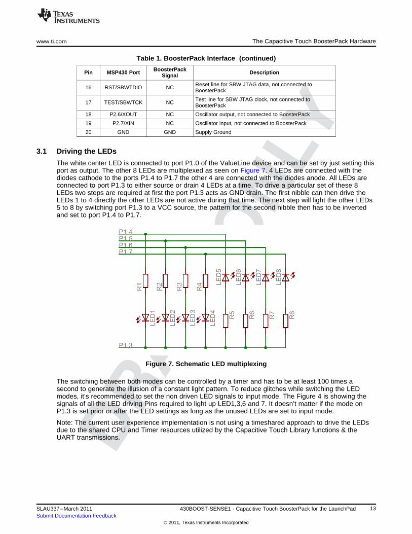
3.1 Driving the LEDs
The white center LED is connected to port P1.0 of the ValueLine device and can be set by just setting thisport as output. The other 8 LEDs are multiplexed as seen on Figure 7. 4 LEDs are connected with thediodes cathode to the ports P1.4 to P1.7 the other 4 are connected with the diodes anode. All LEDs areconnected to port P1.3 to either source or drain 4 LEDs at a time. To drive a particular set of these 8LEDs two steps are required at first the port P1.3 acts as GND drain. The first nibble can then drive theLEDs 1 to 4 directly the other LEDs are not active during that time. The next step will light the other LEDs5 to 8 by switching port P1.3 to a VCC source, the pattern for the second nibble then has to be invertedand set to port P1.4 to P1.7.
Figure 7. Schematic LED multiplexing
The switching between both modes can be controlled by a timer and has to be at least 100 times asecond to generate the illusion of a constant light pattern. To reduce glitches while switching the LEDmodes, it’s recommended to set the non driven LED signals to input mode. The Figure 4 is showing thesignals of all the LED driving Pins required to light up LED1,3,6 and 7. It doesn’t matter if the mode onP1.3 is set prior or after the LED settings as long as the unused LEDs are set to input mode.
Note: The current user experience implementation is not using a timeshared approach to drive the LEDsdue to the shared CPU and Timer resources utilized by the Capacitive Touch Library functions & theUART transmissions.
13SLAU337–March 2011 430BOOST-SENSE1 - Capacitive Touch BoosterPack for the LaunchPadSubmit Documentation Feedback
© 2011, Texas Instruments Incorporated

The Capacitive Touch BoosterPack Hardware www.ti.com
Figure 8. LED driving
3.2 Capacitive Touch sensors
The 6 different Capacitive Touch sensor areas are connected to the port 2 of the device. The pins on port2 of the MSP430 ValueLine devices with enabled Touch-sense I/Os have no analog functionality and asmaller internal capacitance, which make these ports more sensitive than Capacitive Touch sensors onthe port 1. The Capacitive Touch BoosterPack hardware can also be used with other MSP430s theResistors R10 to R15 have to be populated with a resistor to realize a RC discharge which can bemeasured with a timer.
Figure 9. Capacitive Touch sensor areas
The Figure 9 is showing the connection of the Capacitive Touch sensor areas to the MSP430.
The Touch-sense feature of the I/Os can be enabled with setting the secondary port select PxSEL2 andclearing of the PxSEL bit. The selected pins will start oscillating right away and the frequency gives adirect indication about the capacitance connected to the port pin. The Touch-sense I/Os are oscillatingwithin a frequency range from 1 to 2 MHz, which is strongly dependant by the supply voltage, the devicepackage and some environmental influences. For more information about the Touch-sense feature of thenew MSP430 ValueLine devices, some code snippets or applications examples visit the Capacitive TouchBoosterPack wiki page (http://processors.wiki.ti.com/index.php/MSP430_LaunchPad_(MSP-EXP430G2))or take a look at the MSP430 Capacitive Touch Library, also used in the application demo included in thiskit.
14 430BOOST-SENSE1 - Capacitive Touch BoosterPack for the LaunchPad SLAU337–March 2011Submit Documentation Feedback
© 2011, Texas Instruments Incorporated

www.ti.com LaunchPad Capacitive Touch BoosterPack User Experience Firmware
4 LaunchPad Capacitive Touch BoosterPack User Experience Firmware
This chapter describes the firmware application that is provided with the project. Detailed information onthe project was constructed, the usage of the Capacitive Touch Library, and how to set up and import theprojects are also described. The source code for the MSP430G2452 firmware application can be locatedunder [INSTALL_PATH]\Source\ as described in Section 2.2.
This application operates on the LaunchPad platform using the MSP430G2452 device and the CapacitiveTouch BoosterPack plugin board. The capacitive touch and proximity sensing are enabled by the pinoscillator feature new to the MSP430G2xx2 family devices. The User Experience application also utilizesthe Capacitive Touch Library to realize & measure the capacitive touch and proximity sensors. TheCapacitive Touch Library also provides layers of abstractions to generate higher logical outputs such aslogical touches and there position (in this hardware, a four-button wheel).
The User Experience application starts up and remains in 'sleep' mode, sampling the proximity sensorevery ~8.3ms [VLO/100=12kHz/100=120Hz]. Upon registering a valid proximity event hand/finger/objecthovering ~3-5cm from the BoosterPack], the application wakes up to operate in the 'active' mode. Duringthe wake up period, the LEDs surrounding the wheel light in a wake-up sequence, starting with a slowclockwise and ending with a fast counter-clockwise motion. As this sequence ends, the device entersactive mode.
In active mode, the application samples and registers individual finger touches on the 16-position wheel orthe center button as well as simple gestures [Clockwise & Counter-clockwise] while the finger movesalong and remains on the wheel. Upon wheel position detection, the corresponding LEDs surrounding thewheel light up accordingly. Each individual tap on the center capacitive touch button toggles the centerLED.
After a predetermined amount of time without any touch activity (on the wheel or on the center button) theapplication returns to sleep mode, enabling only the proximity sensor periodically.
A 9600 baud UART link is also implemented using SW TimerA to provide application and capacitivesensing data to the PC via the UART-USB back channel. The application sends UART data upon eventssuch as wake up, sleep, touch, or gesture.
For more detailed information on the firmware project, refer to the source code and the associatedReadMe.txt
4.1 Project Import in CCS
(a) Open CCS(b) Select a new project workspace outside of the project folder*(c) Select Project-->Import Existing Project(d) Browse to the [PROJECT_ROOT]\CCS folder(e) Select Finish
*Ideally, workspace should be in completely independent folder, not containing or contained by theproject/package folder.
Note: For CCS, while project root is in the outer directory, the CCS project files are located inside CCS. Toenable the portability of the project, the file macros.ini is created to define the root. Additionally, all projectcode files (*.c, *.h) are added as linked resources with their relative path to the project root.
4.2 Open project & workspace with IAR embedded workbench
(a) Browse to the [PROJECT_ROOT]\IAR folder(b) Open the Sense_BoosterPack_UserExperience.eww workspace.
4.3 Capacitive Touch Library
The Capacitive Touch Library is a configurable tool to abstract the various peripheral settings from theapplication and perform several capacitive touch functions through API calls. The following describes theconfiguration of the library to support the Capacitive Touch BoosterPack, the methodology to calibrate thedifferent elements, and how the API calls are used in the application to create the user experience.
15SLAU337–March 2011 430BOOST-SENSE1 - Capacitive Touch BoosterPack for the LaunchPadSubmit Documentation Feedback
© 2011, Texas Instruments Incorporated

LaunchPad Capacitive Touch BoosterPack User Experience Firmware www.ti.com
1. ConfigurationThe very first step in the configuration process is identifying the methodology used to measure thecapacitance. For the Capacitive Touch BoosterPack the goal is to highlight the new PinOsc featureand therefore an RO implementation is chosen, where the relaxation oscillator is implemented with thePinOsc. The RO implementation requires two timers (hardware or software timers): an interval timer(gate) and a frequency counter. The frequency counter is implemented with the TimerA0 peripheraland the interval timer is implemented with the WDT+.The Capacitive Touch BoosterPack is represented in the various structures defined in the filestructure.c. The element structures define the GPIO and the performance characteristics of eachelement. The GPIO are defined first and then once the appropriate sensor characteristics are definedthe performance characteristics are measured and added.The sensor structure groups elements as appropriate and identifies the measurement characteristic forthat group, namely the interval period. For the RO method increasing the interval time increases thesensitivity, but this is at the cost of response time which is critical for supporting the PC GUI in thisapplication.The proximity sensor uses an SMCLK of 125KHz while for the button and wheel the frequency isincreased to 1Mhz. The interval count is 8192: 8.192ms gate time for the button and wheel elementsand 65.5ms for the proximity element. The wheel is a special kind of sensor where each elementcontributes to the sensor performance. The wheel is made up of 4 elements, divided into 64 points orsections, and requires that the cumulative response exceed 75 percent. This last point is based uponthe normalized response where meeting the threshold would represent 0% and the maximum responsewould represent 100%. This is to account for cases when the interaction is near the edges of the wheelinstead of the middle.
2. CalibrationThe calibration of the middle button and the proximity sensor are relatively straight forward since thedesired output is simply a binary indication if the threshold is exceeded or not. Using a controlled testfixture to represent the minimum touch (distance in the case of the proximity sensor), the values arerecorded and input as the threshold value in the element structure.The calibration for the wheel was a little more complicated, as several measurements are required atvarious positions. Please refer to section “Sensor arrays: Wheels and Sliders” in SLAA490 for a moredetailed explanation.The calibration values for each element are recorded in the element structure in the file structure.c.
3. API CallsThere are 5 different API functions which are called several times throughout the application.
• The TI_CAPT_Init_Baseline and TI_CAPT_Update_Baseline functions are used to initialize andupdate the baseline tracking performed by the library. Typically these functions are called at thebeginning of an application or after long periods of inactivity. In this user experience code theinitialization and updates are performed at the beginning after a power up sequence and alsobefore a transition from the sleep (polling proximity sensor only) to active (polling button and wheelonly). These functions are used at the transitions because it is unknown how old the previousmeasurements are and if these still represent the current environment.
• The TI_CAPT_Custom function is used to measure the proximity sensor. The variable dCnt isupdated with the measured value. In the application, this variable is compared to a threshold value.Since this is a simple On/Off function the TI_CAPT_Button function could have been used, but fordemonstration purposes the TI_CAPT_Custom function was chosen. Once a threshold crossing isdetected an LED sequence is started and the application transitions to the active state (polling thewheel and middle button). One possible enhancement of the proximity sensor application is toenable several different thresholds and indicate how close the user is with the LEDs on theBoosterPack.
• The TI_CAPT_Button function is used to determine if the middle button has been detected. This isa fairly straightforward function returning either a 0 or 1 to indicate a threshold crossing (touch). Themiddle LED is illuminated to indicate a touch.
• The TI_CAPT_Wheel function indicates the position on the wheel if touched or simply returns adefined illegal value if no touch was detected. This information is used by the application forgesture recognition (which is sent to the PC) and for illuminating the 8 LEDs around the board.
For more information on the library, refer to the Capacitive Touch Library documentation. (SLAA490)
16 430BOOST-SENSE1 - Capacitive Touch BoosterPack for the LaunchPad SLAU337–March 2011Submit Documentation Feedback
© 2011, Texas Instruments Incorporated

www.ti.com LaunchPad Capacitive Touch BoosterPack User Experience Software
5 LaunchPad Capacitive Touch BoosterPack User Experience Software
5.1 LaunchPad Capacitive Touch BoosterPack User Experience GUI
Written in Processing, this Windows PC GUI application communicates with the LaunchPad to receivespecific capacitive touch data from the LaunchPad Capacitive Touch BoosterPack and provides thevisualization of said information in the GUI. Processing is a platform independent open sourceprogramming language and environment, specialized on visual arts, graphics and interactive applications.
The GUI uses a small .NET utility (FindAppUART.exe) to automatically detect a properLaunchPad/430Emulator device connected to the PC USB port. Upon correct USB COM port discovery,the application initiates a 9600baud UART connection and starts receiving data.
The GUI processes event and capacitive touch data and visualizes said information on the GUI in a16-slice wheel formation. Individual touches as well as gestures can be tracked in real time.
Further description of the behavior can be found in the Getting Started chapter (2.3.2) and the ReadMe.txtin the project source code directory.
The application also takes advantage of the serial library for USB COM serial communication, and thesound library pitaru.sonia_v2_9.* (available at http://sonia.pitaru.com/download.htm) for audio effects.
5.1.1 Requirement
- Processing download from http://www.processing.org
- serial library [included with processing installation]
- pitaru.sonia_v2_9 sound library: http://sonia.pitaru.com/download.htm
- FindAppUART.exe: [included .NET utility]
5.2 MediaPad
The program MediaPad, written using Visual Studio, translates capacitive touch data from from theLaunchPad Capacitive Touch BoosterPack into Microsoft Windows virtual keystrokes for Windows mediacontrol. The application implements auto-detection code that automatically seeks for aLaunchPad-compatible USB COM port before establishing the proper connection. Further behavior of theapplication is described in the Getting Started chapter (2.3.3) and the ReadMe.txt in the project sourcecode directory.
5.2.1 Requirements
Microsoft Visual C++ 2010 Redistributable Package (included in any version of Visual Studio 2010).(available at http://www.microsoft.com/downloads)
5.3 UART Communication Protocol
Per each event (wake up, go to sleep, touch/press, or gesture), a UART packet of two bytes is sent viathe Application UART back channel of the LaunchPad. They are specified as follows:
• WAKE UP [due to proximity sensor detection]: 0xBE 0xEF• SLEEP [after period of inactivity]: 0xDE 0xAD• CENTER BUTTON PRESS: 0x80 0x80• WHEEL POSITION TOUCH/PRESS: 0x3z 0x3z [z = touch position 0x0-0xF, one nibble]• GESTURE START: 0xFC 0x2z [z = touch position 0x0-0xF, one nibble]• GESTURE STOP: 0xFB 0xFB• GESTURE & GESTURE END POSITION : 0xGG 0x2z GG = [binary] b????????
GG: MSB is direction: 0 = clockwise, 1 = counter-clockwise; last 7 bits = count of gesture movementz = ending position of the immediate gesture, 0x0-0xF, one nibble.
The PC applications can receive and decipher the UART information to translate them into appropriateactions.
17SLAU337–March 2011 430BOOST-SENSE1 - Capacitive Touch BoosterPack for the LaunchPadSubmit Documentation Feedback
© 2011, Texas Instruments Incorporated

Frequently Asked Questions (FAQ), Tips & Tricks www.ti.com
6 Frequently Asked Questions (FAQ), Tips & Tricks1. The LaunchPad is unable to program the MSP430G2452.
Some of the revision 1.4 LaunchPads have problems with supporting the MSP430G2452 devices.Please update the LaunchPad firmware with the application provided herehttp://processors.wiki.ti.com/index.php/MSP430_LaunchPad_Firmware_Update.
2. The Touch-sense I/Os are not working when the LaunchPad is picked up?Place board flat on the table before using the Capacitive Touch BoosterPack. Do not hold the sides ofthe board while in use. The contacts on the back of the Capacitive Touch BoosterPack are otherwisetouched and the Touch-sense I/Os are not able to detect user interaction.
3. My application is not able to light up all the LEDs?The LEDs around the wheel are multiplexed, hence they can’t all be turned on simultaneously. Itsrequired to use a timeshared approach to light up all LEDs at one. See chapter Section 3.1.
4. The button or the wheel is sometimes not detecting the first touch.Make sure to wave hand to wake up the device before actually touch the wheel or button. Thecapacitive sensors are activated right after the wake up sequence is finished.
5. Windows player is not starting.Loading Windows Media Player might take some time, depending on the system. On some systemsanother Media Player program is associated with the windows media keys.
7 Reference
The primary sources of MSP430 information are the device-specific data sheets and user's guides. Themost up-to-date versions of those documents can be found at the Texas Instruments MSP430 page or theMSP430 LaunchPad wiki.
www.ti.com/msp430, http://processors.wiki.ti.com/index.php/MSP430_LaunchPad_(MSP-EXP430G2)
For in-depth knowledge on the supporting IDEs such as CCS and IAR, download the latest version fromthe web pages above and refer to included user's guides and documentation inside the installation folder.Documents describing the IAR tools (Workbench/C-SPY, the assembler, the C compiler, the linker, andthe library) are located in common\doc and 430\doc. All necessary CCS documents can be found insidethe msp430\doc inside the CCS installation path.
The FET user's guide also includes detailed information on how to set up a project for the MSP430 usingIAR or CCS, and it is included in most of the IDE releases and on the TI MSP430 side.
18 430BOOST-SENSE1 - Capacitive Touch BoosterPack for the LaunchPad SLAU337–March 2011Submit Documentation Feedback
© 2011, Texas Instruments Incorporated
www.ti.com Appendix
8 Appendix
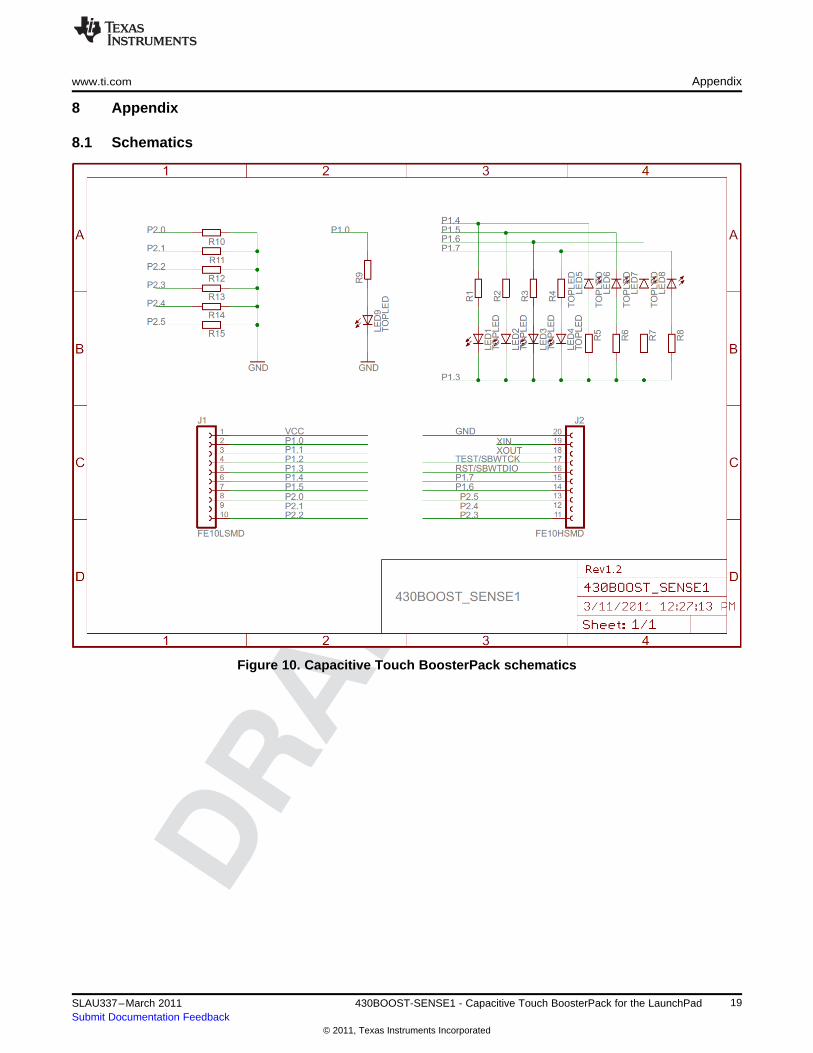
8.1 Schematics
Figure 10. Capacitive Touch BoosterPack schematics
19SLAU337–March 2011 430BOOST-SENSE1 - Capacitive Touch BoosterPack for the LaunchPadSubmit Documentation Feedback
© 2011, Texas Instruments Incorporated

Appendix www.ti.com
8.2 PCB Layout
Figure 11. Capacitive Touch BoosterPack layout top layer
Figure 12. Capacitive Touch BoosterPack layout bottom layer and silkscreen
8.3 Bill of Materials (BOM)
Table 2. Bill of Materials
Number perPos. Ref Name DescriptionBoard
1 R1-8 8 390Ohm SMD0603 Resistor
2 R9 1 180Ohm SMD0603 Resistor
3 LED1-8 8 TOPLED RED WTR CLR 631NM 1206
4 LED9 1 LED WHITE ROUND DIFFUSED 1206
5 J1, J2 2 Female Header SSM-110-L-SV 2.54mm
6 R10-15 0 SMD0603 Resistor (Not populated)
20 430BOOST-SENSE1 - Capacitive Touch BoosterPack for the LaunchPad SLAU337–March 2011Submit Documentation Feedback
© 2011, Texas Instruments Incorporated


