ms, Inc. All rights reserved worldwide. No parts of this manual, in whole or in part, may be d, translated, or transmitted to any electronic medium or machine readable form without mission of FLIR Systems, Inc.
es not contain export-controlled information
Names and marks appearing on the products herein are either registered trademarks or trademarks of FLIR Systems, Inc. and/or its subsidiaries. All other trademarks, trade names, or company names referenced herein are used for identification only and are the property of their respective owners.This product is protected by patents, design patents, patents pending, or design patents pending.The contents of this document are subject to change. FLIR Systems, Inc.6769 Hollister AvenueGoleta, CA 93117Phone: 888.747.FLIR (888.747.3547)International: [email protected]
Proper Disposal of Electrical and Electronic Equipment (EEE)The European Union (EU) has enacted Waste Electrical and Electronic Equipment Directive 2002/96/EC (WEEE), which aims to prevent EEE waste from arising; to encourage reuse, recycling, and recovery of EEE waste; and to promote environmental responsibility.In accordance with these regulations, all EEE products labeled with the “crossed out wheeled bin” either on the product itself or in the product literature must not be disposed of in regular rubbish bins, mixed with regular household or other commercial waste, or by other regular municipal waste collection means. Instead, and in order to prevent possible harm to the environment or human health, all EEE products (including any cables that came with the product) should be responsibly discarded or recycled.To identify a responsible disposal method where you live, please contact your local waste collection or recycling service, your original place of purchase or product supplier, or the responsible government authority in your area. Business users should contact their supplier or refer to their purchase contract.
Document HistoryVersion Date Comment100 December 2017110 July 2018 Added support for cryocooler control; three new visible camera modes: wide
dynamic range, defog, and electronic stabilization; additional GUI language support for Español and Türkҫe; simplified automatic gain controls; updated password security
432-0012-01-12 Version 110 2 August 2020
RMogster
Rectangle
RMogster
Typewriter
August 2020
Contents
Installing the M500
General Information..................................................................................................... 5Standard Features ................................................................................................. 5Additional Installation Components ....................................................................... 6Additional References ........................................................................................... 6
Warnings and Cautions ............................................................................................... 7
System Installation .................................................................................................... 11Installing the Joystick Control Unit (JCU II) ......................................................... 12
Installation of other Shipboard Systems.................................................................... 18NMEA 0180 Interface .......................................................................................... 18
M500 Reference
M500 Maintenance.................................................................................................... 19Cleaning the JCU II ............................................................................................. 19Cleaning the Camera Optics ............................................................................... 19Cleaning the Camera Body ................................................................................. 19
M500 Web Browser Interface .................................................................................... 23View Camera and JCU II IP Address .................................................................. 24Camera Web Server Login Accounts .................................................................. 24Log in to the Camera Web Server ....................................................................... 24Setup Menu ......................................................................................................... 28Maintenance Menus ............................................................................................ 33Changing Video Outputs ..................................................................................... 37Geo-Referencing of the Sensors ......................................................................... 39Software Update.................................................................................................. 40Accessing the JCU II Web Interface.................................................................... 40
Enabling Universal Plug and Play (UPnP) ................................................................ 41UPnP Overview ................................................................................................... 41Enabling the UPnP User Interface....................................................................... 41
Mechanical ICD Reference
M500 Top Down Riser Installation Template ............................................................. 47
M500 Interface Control Document ............................................................................... 52Joystick Control Unit Interface Control Document........................................................ 53Maritime/Tracker Joystick Control Unit Interface Control Document............................ 54M500 Riser Installation Document ............................................................................... 55
432-0012-01-12 Version 110 4 August 2020
1
Installing the M500
General InformationThis manual describes the installation of the M500 system. If you need help or have additional questions, please call to speak with our support experts; refer to contact information listed on the back cover of this manual.
The multi-sensor M500 is a stabilized maritime thermal and high definition (HD) visible-light camera system for use on most types of vessels. The mid-wave infrared (MWIR) thermal camera with 14X optical zoom provides excellent nighttime visibility and situational awareness, without any form of natural or artificial illumination. The HD visible-light camera with 30X optical zoom provides daytime viewing.
Standard Features• Pan/Tilt provides continuous 360° pan and +/- 90° tilt.
• Active gyro-stabilization provides steady, long-range viewing.
• Video tracking locks on and follows objects as long as they are in view.
• High intensity LED spotlight
M500 Pan/Tilt Camera System
LED spotlight
Thermal camera
HD visible-lightcamera
432-0012-01-12 Version 110 5 August 2020
General Information
The M500 should be installed by a qualified marine electronics technician; incorrect installation could void the warranty.
This manual includes information about the following topics:
• Installation overview and planning
• Mounting the camera and installing the Joystick ControlUnit (JCU II)
• Connecting the electronics
• Configuration and Communication using a PC
• Maintaining the camera
• Parts list and other reference information
Additional Installation Components
Contact FLIR Systems, Inc. for more information regarding available accessories including additional JCU IIs, PoE equipment, video distribution amplifiers, Serial to Ethernet servers, NMEA Multiplexers, etc.
Additional ReferencesYour M500 camera comes with a complete documentation set available from the FLIR Systems, Inc. Web site. All documents are in PDF format and can be viewed with Adobe Acrobat Reader:
• M500 Operator’s Manual (FLIR Doc. # 432-0012-01-10) contains information about how toconfigure and operate the camera.
• M500 Quick Start Guide (FLIR Doc. # 432-0012-01-11) is a card used as a reference for thefunctions executed by the various JCU II buttons.
• M500 ICD (FLIR Doc. # 432-0012-05-41) is an Interface Description Document providingdetailed installation information.
For safety, and to achieve the highest levels of performance from the M500 system, always follow the warnings and cautions in this manual when handling and operating the M500 camera system.
Warning notices are used to emphasize conditions that could cause personal injury or death existing with this equipment, or that may be associated with its use.
Caution notices are used where equipment might be damaged if care is not taken or an operation might have an unexpected outcome.
Notes call attention to information significant to understanding and operating the equipment.
432-0012-01-12 Version 110 6 August 2020
Warnings and Cautions
Warnings and CautionsWarning: Do not use the M500 imaging system as the primary navigation system. Use it in conjunction with other navigation aids and a primary manual navigation system.
Warning: Ensure power is removed before accessing power wires during installation or removal of system components. DO NOT HOT SWAP components (such as the JCU II). Damage to equipment or injury to personnel may result.
Warning: The M500 system is not designed to operate in an enclosed environment in the presence of flammable gases. Failure to follow this warning may result in explosion or fire.
Warning: Use of insufficient wire gauge can result in fire.
Warning: The M500 camera body is a remotely and automatically controlled device. Ensure camera motion has been disabled before cleaning surfaces that can cause pinch hazards.
Caution: Do not open the M500 camera unit for any reason. Disassembly of the camera (including removal of the cover) can cause permanent damage and will void the warranty.
Caution: Be careful not to leave fingerprints on the M500 camera optics.
Caution: The M500 requires a power supply of 12 Vdc to 24 Vdc nominal, 5.5 A maximum @ 24 Vdc, 11 A maximum @ 12 Vdc. Absolute voltage range: 12 Vdc to 32 Vdc. Operating the camera outside of the specified input voltage range or the specified operating temperature range can cause permanent damage.
Caution: During installation, ensure the cables exiting the camera are not in contact with sharp edges, do not bend at sharp angles, and are not pinched between the bottom of the camera and the mounting surface. Do not pull on the cables with excessive force.
Operating temperature range –20 °C to +55 °C (–4 °F to +131 °F) per IEC 60945
Storage temperature range –50 °C to +80 °C (–58 °F to +176 °F)
432-0012-01-12 Version 110 7 August 2020
Installation Overview
Installation OverviewThe M500 includes these standard components:
The standard cable set shipped with the M500 system is shown below in Figure 1-1. See “M500 Interface Control Document” on page 52 for the location of cable connections on the bottom of the M500 camera.
Contact FLIR Systems, Inc. for information on additional cables, shown in Table 1.1, which may be purchased.
308-0263-01-00 - Power cable - right angle, 12 AWG, 1 m
308-0261-01-00 - Ethernet cable - right angle to RJ45, 1 m4115028 - RJ45 waterproof enclosure coupler
308-0265-01-00 - AV and serial cable - right angle, 1 m
M500 Pan/Tilt Camera432-0012-05-00
Joystick Control UnitPN 500-0398-10
5-port PoE+ Ethernet SwitchPN 4141042
NMEA and Factory test
F-type connector
serial interface
432-0012-01-12 Version 110 8 August 2020
Installation Overview
308-0267-00 - HD-SDI cable, 1 m
4142057 - HD-SDI isolation transformer
Figure 1-1: Standard Cable Set
TABLE 1.1 Additional Cables Available from FLIR
Part Number Description
308-0260-01-00 Cable - Ethernet to RJ45, 1 m308-0262-01-00 Power Cable - 12 AWG, 1 m308-0264-01-00 Cable - AV and serial, 1 m4141864 Cable - HD/SDI, 100 ft308-0251-30-00 Cable - Ethernet to RJ45, 100 ft, LSZH308-0252-30-00 Cable - Ethernet, RA to RJ45, 100 ft, LSZH308-0253-30-00 Cable - Power, 12 AWG, 100 ft, LSZH308-0254-30-00 Cable - Power, right angle, 12 AWG, 100 ft, LSZH308-0255-30-00 Cable - AV and serial, 100 ft, LSZH308-0256-30-00 Cable - AV and serial right angle, 100 ft, LSZH
BNC connectors (2)
HD-SDI Isolation Transformer
BNC connectors (2)
refer to the latest released ICDfor installation requirements
to display Input from camera
M6x1 16 mm SHCS (6)
41411973 - Top down riser
Washer M6 (6)
Riser gasket
Vinyl transferFLIR logos
Figure 1-2: Top down riser kit
432-0012-01-12 Version 110 9 August 2020
Installation Overview
You will need to supply the following items depending on the planned installation:
• For Top Down Riser—Six (6) M8 stainless steel bolts and washers to secure the top down riserafter the camera is attached—bolt length depends on mounting platform thickness.Recommended:M8 socket head cap screws, or5/16” - 18 socket head cap screws, or5/16” - 18 hex head sheet metal screws type 316 stainless steelApply thread locker (Loctite 262 or equivalent)
• One or more multi-function displays (MFD) or other analog or digital video display devices
• Coaxial RG6 video cable to customer-supplied analog video monitors
• Coaxial RG6 video cable to customer-supplied HD-SDI digital video monitors
• Ethernet cables to connect the M500 and the JCU II to the PoE Ethernet switch,8-conductor T568B
• Ethernet cables to connect to the ship’s Ethernet port,8-conductor T568B
• Miscellaneous electrical hardware, connectors, and tools
General Location Considerations
Warning: The M500 system is not designed to operate in an enclosed environment in the presence of flammable gases. Failure to follow this warning may result in explosion or fire.
First determine a good location for mounting the M500 system body and the JCU II. The system has four cable connections:
• Power
• Ethernet connection to PoE switch for the JCU II; the switch requires an Ethernet connection tothe JCU II and optionally to other JCU II controllers or to a shipboard network.
• HD-SDI digital video
• Composite analog video and serial data (NMEA and factory test)
More than one JCU II can be installed to control the camera and more than one display can be used to view the video. Also, a single JCU II can be used to control more than one camera. Most often, the JCU II and video monitor are mounted close together, as a pair, so the video can be viewed when the camera position (pan, tilt, zoom) is changed with the JCU II.
When determining the component locations, consider how the system may be expanded in the future. For example, adding an additional monitor, or perhaps a JCU II and monitor pair.
Consider the following points when determining the camera location:
• Mount the M500 camera body as high as practical, but without interfering with any radar,navigational, or communications electronics.
• To minimize interference with video signals, the camera body must be mounteda minimum of 1 meter away from any radio frequency antenna.
• Minimize the degree to which vessel structures block the camera’s 360° view. The camera’scontinuous-pan design lets it rotate and point in all directions.
432-0012-01-12 Version 110 10 August 2020
System Installation
• It is a good practice to test the unit at the planned installation location with typical vesselelectronics active prior to mounting the camera.
• Mount the camera as close to the vessel’s center line as possible so you will have asymmetrical view of on-coming traffic, obstacles, and other navigational hazards.
• The M500 camera has a “forward” direction adjustment which has been set atthe factory. This is the direction directly toward the front of the vessel. Icons onthe video show the direction the camera is facing in relation to an outline of aship. Refer to the latest Interface Description Document for details. Afterinstallation, the forward direction of the camera must be verified and adjusted ifrequired. Refer to M500 Operator’s Manual (FLIR Doc. # 432-0012-00-10).
Note: When the camera is mounted upside down (ball down), the camera base must be rotated backwards, to point toward the stern of the vessel.
• An appropriate camera mount suited for the camera mass and potential vibration andmechanical shock is important for proper camera functioning. The camera is tested to holdposition for mechanical shock up to 9 G transverse and 15 G vertical. Improper mounts that areloose and/or resonate can magnify vessel impacts causing the camera to be unable to maintainpointing direction.
• When selecting a mounting location for the M500 system, consider cable lengths and cablerouting. Ensure the cables are long enough, given the proposed mounting locations and cablerouting requirements, and route the cables before you install the components.
• Use power cables that have sufficient dimensions to ensure safety and video andcommunication cables that have sufficient dimensions to ensure adequate signal strength.
• To ensure a proper seal between the camera unit and the vessel, an O-ring should be installedin the camera base. The O-ring will seal properly with a surface that is flat to within 1.5 mm(0.06 in) over the diameter of the base of the camera. If it is necessary to install on a surfacethat does not meet this criteria, a marine-grade sealant (3M 4200 or equivalent) must be usedrather than the O-ring.
• A final location consideration is the relation between the camera and other navigation devices.If relying on a magnetic compass for navigation and direction, establish a “compass safedistance” for any object placed in its vicinity, especially any electronic equipment. The magneticcompass safe distance for the camera is 40 cm (15.7 in).
System InstallationIn most installations, the M500 is mounted upright on top of a mounting surface, with the pan/tilt base below the camera; this is known as the ball up orientation. Optionally, the unit can be hung upside down or ball down. Once the mounting location has been selected, verify that both sides of the mounting surface are accessible. The camera mounting surface must be at least as large as the footprint of the camera itself to ensure an adequate seal with the O-ring.
Use a thread-locking compound such as Loctite 262 or equivalent with all metal-to-metal threaded connections.
Caution: Use all six mounting holes to secure the camera rigidly.
As an alternative to a mounting O-ring, you can use a marine-grade sealant such as 3M 4200 or the equivalent.
432-0012-01-12 Version 110 11 August 2020
System Installation
Mounting Upright
The cable connectors terminating the pigtail cables on the camera are waterproof, vibration tolerant, twist pin connectors designed for the marine environment. Appropriate sealing steps are needed when making connections to on-board systems.
Caution: If you print the template from the PDF file, ensure that it is printed to the correct scale by checking the dimensions prior to cutting any holes.
Using the template as a guide, mark the location of the holes for mounting the camera
Once the holes are drilled in the mounting surface, thread the power supply, video, and Ethernet cables from the camera through the center hole, and then place the camera on the mounting surface so the mounting bolts extend through the drilled holes. Secure and seal the camera body to the mounting surface.
Mounting Upside Down
When a camera is going to be mounted upside down (ball down), a menu setting is used to configure the system for ball down operation. Set the camera orientation after the camera is installed. Refer to the M500 Operator’s Manual.
Installing the Joystick Control Unit (JCU II)
Mount the JCU II in an area that is close to the monitor being used to display the M500 video output. Make sure the area you choose leaves enough room for the cable under the JCU II. The magnetic compass safe distance from the JCU II is 55 cm (21.7 in).
The JCU II can be mounted to the dash in any orientation, using four captive mounting screws that hold panel mounting clamps. When the mounting screws are tightened, the panel mounting clamps rotate and extend away from the JCU II at a right angle, and come into contact with the mounting surface. The JCU II can be mounted to dash thicknesses ranging from 0.16 cm to 4.45 cm (0.063 in to 1.750 in). A trim bezel snaps on top of the JCU II to cover the mounting screws.
The JCU II is a Power over Ethernet (PoE) device and can be connected to either the supplied PoE Ethernet Switch or a customer supplied PoE injector.
To ensure a proper seal around the JCU II, the supplied gasket must be applied to the JCU II and the cutout opening for the JCU II should precisely match the template. If the cutout opening is too large, the gasket around the JCU II may not cover the opening adequately.
The cable gland seal is designed for use with double-shielded category 5 Ethernet cable. To ensure a good seal and to maintain compliance with EMI ratings, a double-shielded cable is required.
Caution: If you print the template from the PDF file, ensure that it was printed to the correct scale by checking the dimensions prior to cutting any holes.
Joystick Control Unit
432-0012-01-12 Version 110 12 August 2020
System Installation
Standard JCU II Mounting Instructions
1. Using the JCU II template supplied as a guide, mark thelocation of the rectangular opening that will allow the JCU IIto be recessed in the vessel’s control console. Ensure thecorners are marked precisely and cut square.
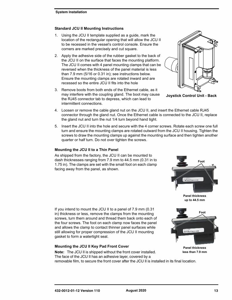
2. Apply the adhesive side of the rubber gasket to the back ofthe JCU II on the surface that faces the mounting platform.The JCU II comes with 4 panel mounting clamps that can bereversed when the thickness of the panel material is lessthan 7.9 mm (5/16 or 0.31 in); see instructions below.Ensure the mounting clamps are rotated inward and arerecessed so the entire JCU II fits into the hole
3. Remove boots from both ends of the Ethernet cable, as itmay interfere with the coupling gland. The boot may causethe RJ45 connector tab to depress, which can lead tointermittent connections.
4. Loosen or remove the cable gland nut on the JCU II, and insert the Ethernet cable RJ45connector through the gland nut. Once the Ethernet cable is connected to the JCU II, replacethe gland nut and turn the nut 1/4 turn beyond hand tight.
5. Insert the JCU II into the hole and secure with the 4 corner screws. Rotate each screw one fullturn and ensure the mounting clamps are rotated outward from the JCU II housing. Tighten thescrews to draw the mounting clamps up against the mounting surface and then tighten anotherquarter or half turn. Do not over tighten the screws.
Mounting the JCU II to a Thin Panel As shipped from the factory, the JCU II can be mounted to dash thicknesses ranging from 7.9 mm to 44.5 mm (0.31 in to 1.75 in). The clamps are set with the small foot on each clamp facing away from the panel, as shown.
If you intend to mount the JCU II to a panel of 7.9 mm (0.31 in) thickness or less, remove the clamps from the mounting screws, turn them around and thread them back onto each of the four screws. The foot on each clamp now faces the panel and allows the clamp to contact thinner panel surfaces while still allowing for proper compression of the JCU II mounting gasket to form a watertight seal.
Mounting the JCU II Key Pad Front CoverNote: The JCU II is shipped without the front cover installed. The face of the JCU II has an adhesive layer, covered by a removable film, to secure the front cover after the JCU II is installed in its final location.
Joystick Control Unit - Back
Panel thicknessup to 44.5 mm
Foot
Panel thicknessless than 7.9 mm
Foot
432-0012-01-12 Version 110 13 August 2020
Electrical Connections
1. Pull up the tab to remove the adhesiveprotection film and expose the adhesivelayer.
2. Install the key pad front cover over thejoystick ensuring that the joystick bootis not caught between the cover and theJCU II.
3. Position the cover starting with thebottom corners and then press into theadhesive on all edges. The covershould snap into place flush with theJCU II bezel.
Electrical ConnectionsWatertight connectors/enclosures should be used on each of the electrical connections. Table 1.2 describes the connections for the cables attached to the camera.
Warning: Ensure power is removed before accessing power wires during installation or removal of system components. Damage to equipment or injury to personnel may result.
Caution: During installation, ensure the cables exiting the bottom of the camera are not in contact with sharp edges, do not bend at sharp angles, and are not pinched between the bottom of the camera and the mounting surface. Do not pull on the cables with excessive force.
Caution: It is recommended that any built-up triboelectric charge on the Ethernet cable should be discharged before connecting it to the JCU II and camera. This can be accomplished simply by pressing an ungloved finger across the Ethernet RJ45 connector of the cable for a few seconds.
TABLE 1.2 Connections Quick Reference
Cable Label Connectors Comment
Power Red Nominal 24 Vdc Absolute range 12 Vdc to 32 Vdc 2.5 A typical, 5.5 A max maximum @ 24 Vdc;5 A typical, 11 A max maximum @ 12 Vdc
Black Vdc return
Drain Chassis ground
HD/SDI BNC style Coax Digital video with isolation
Analog Video and serial cable
F-type style Coax and pigtailfor serial (NMEA/factory test)
Analog video
Ethernet RJ45 Use shielded Ethernet cable for connection to PoE switch providing power to JCU II and optional connection to shipboard network.
Key Pad Front Cover
Pull tab toexpose adhesive
Ensure bootis clear of cover
432-0012-01-12 Version 110 14 August 2020
Electrical Connections
Connecting Power
The camera itself does not have an on/off switch. Generally the camera will be connected to a circuit breaker and the circuit breaker will be used to apply or remove power to the camera. When power is supplied, the camera will be in one of three modes: Booting Up, Standby, Parked, or Powered On. The M500 Operator’s Manual has detailed information about powering and operating the camera.
Installation of a circuit breaker (or fuse) in line with the power connection is required to protect the power wiring and camera from power surge or short circuit.
The installer must use power cable wires that are sufficient size gauge or diameter for the supply voltage and total load (camera and length of cable run), to ensure proper supply voltage at the camera and adequate current carrying capacity.
Warning: Use of insufficient wire gauge can result in fire. Wire gauge depends on supply voltage shown. For lower supply voltages, lower gauge wire must be used.
Proper Grounding
Caution: Ensure the camera is properly grounded. Following best grounding practices, the camera chassis ground should use the lowest resistance path possible.
Failure to provide this connection may result in electrical interference between camera and other shipboard electronic systems. Furthermore, it is recommended that a bonded grounding scheme is used with a common ground between the chassis ground and electrical return, with the connection made as close as possible to the negative terminal of the battery.
Video Connections
Video cables of various lengths with different connectors at one end are available from FLIR. The video cable used should be rated as RG6 to ensure an adequate quality video signal. For cable runs in excess of 100 ft, a video amplifier should be used.
Ethernet Connections
The Ethernet cable from the camera can be connected to another Ethernet cable with an RJ45 waterproof enclosure connector (FLIR PN 4115028). The Ethernet network cable should be 8-conductor T568B, Ethernet, double-shielded for EMI considerations.
TABLE 1.3 Fuse Recommendation
Model Fuse
M500 12 amp, slow blow at lowest voltage range (12 Vdc)
TABLE 1 4. Typical Power Cable Wire Gauge
Length in Meters (Feet)
Wire Gauge (AWG) for 12V Supply
Wire Gauge (AWG) for 24V Supply
8 (25) 16 1816 (50) 14 1824 (75) 12 16
32 (100) 10 16
432-0012-01-12 Version 110 15 August 2020
2
Installation Examples
This chapter describes several typical installations using standard and optional accessories.
Basic Standard InstallationThe JCU II selects which video output to view (IR or visible) on the monitor and to control the camera configuration using the OSD menus. If two JCU II are used (see Figure 2-2), typically, they are installed in different locations aboard the vessel, each with a monitor. They both can be switched on and enabled at the same time. The video to the monitor can be either the HD-SDI video signal or the composite analog video signal to match the customer supplied monitor. NMEA/ serial data connections and digital IP video connections are not shown below.
Video StreamsThe M500 system provides five configurable video outputs.
Two video streams are provided on separate connectors:
• one analog composite video
• one HD-SDI digital video
Both video streams are configurable using the camera Web Server to show video from theactive camera, the secondary camera, or to always show video from one or the other.
Three digital video streams are provided over the Ethernet connector:
• VIDEO_0 always shows the DLTV visible stream (HD res)
• VIDEO_2 always shows the IR stream (HD res)
• VIDEO_4 always shows Live View (low res) video on the camera Web Server pageconfigurable to show the active camera, the secondary camera, or to always show videofrom one or the other.
Dashed lines represent connection to power
Ethernet Video signal
JCU II
Customer supplied monitor
PoE switch
Figure 2-1: Basic Single-Station System
432-0012-01-12 Version 110 16 August 2020
Digital Video and PC Interface
Digital Video and PC InterfaceA computer (PC) on the network can control and configure the camera using a web browser (refer to “IP Interface and PC Operations” on page 23). Additionally, both IR and DLTV digital video streams are available on the Ethernet connection to a shipboard network for use by a video management system (VMS) or a network video recorder (for example, FLIR DNR400 Series) to record video streams and provide other features such as video storage and backup. Refer to the documentation for the VMS or video recorder for operation and setup details.
FLIR DNR400-Series Connection1. Open a web browser and enter the camera IP address to log in with the admin user name.
2. Ensure that the VMS Remote INTERFACE 1 driver (ONVIF v2.0) is enabled. Refer to“Maintenance->Sensor->Communications->VMS Remote” on page 35.
3. Connect the camera Ethernet to the switch, as shown in Figure 2-2.
4. Connect the video recorder on the same Ethernet network.
The DNR400 video recorder must be connected to the Internet to utilize services.
5. Follow the instructions in the VMS or video recorder documentation to discover the camera.
Digital Video/Control
Ethernet
Dashed lines represent connection to power
PC
Analog Video
HD-SDI Video
JCU II
Customer supplied monitor
Customer supplied monitor
PoE Switch
Customer supplied
Isolationtransformer
1 m or less
Network Video Recorder
Figure 2-2: System with Video Recorder
432-0012-01-12 Version 110 17 August 2020
Installation of other Shipboard Systems
Installation of other Shipboard SystemsNMEA 0180 InterfaceSerial NMEA 0183 interface devices (radar interface for example) can be connected via a Serial port into the M500 system. The NMEA serial interface is included as pigtail leads on the composite analog video/serial cable.
Dashed lines represent connection to power
Analog Video
Customer supplied monitor
NMEA serial inteface
Customer supplied
Ethernet
JCU II
PoE switch
Figure 2-3: Shipboard System
432-0012-01-12 Version 110 18 August 2020
3
M500 Reference
M500 MaintenanceThe M500 components are designed for years of rugged, trouble-free use.
Cleaning the JCU IITo clean the JCU II, use a soft cloth and clean water. Mild household cleaner such as Windex can also be used to remove tougher stains or spots. Do not use alcohol based cleaners or any type of solvents as this may discolor or damage the unit.
Cleaning the Camera Optics
Warning: The M500 camera body is a remotely and automatically controlled device. Ensure camera motion has been disabled before cleaning surfaces that can cause pinch hazards.
Great care should be used with your camera's optics. They are delicate and can be damaged by improper cleaning. The M500 thermal camera lenses are designed for the harsh outdoor environment and have a coating for durability and anti-reflection, but may require cleaning occasionally. FLIR Systems, Inc. suggests that you clean the lens when image quality degradation is noticed or excessive contaminant build-up is seen on the lens.
Rinse the camera housing and optics with low pressure fresh water to remove any salt deposits and to keep it clean. If the front window of the camera gets water spots, wipe it with a clean soft cotton cloth dampened with fresh water. If the window requires further cleaning, use a soft moist cotton-based cloth with Isopropyl alcohol or dish soap.
Do not use abrasive materials, such as paper or scrub brushes as this will possibly damage the lens by scratching it. Only wipe the lens clean when you can visually see contamination on the surface.
Cleaning the Camera Body
Warning: The M500 camera body is a remotely and automatically controlled device. Ensure camera motion has been disabled before cleaning surfaces that can cause pinch hazards.
Caution: The M500 is sealed at the factory against liquid water, suspended particulates, and other contaminants. It is important that you not open the camera for any reason, as it will compromise this seal and possibly damage the unit. Opening the M500 camera will void the manufacturer’s warranty.
Do not pressure wash the camera, especially around the FLIR logos, as that could force water through the camera seals. Clean the interface between the yoke and base often to prevent accumulation of debris or salt deposits.
If you have a problem with your thermal camera, do not attempt to repair it yourself. The M500 camera is a sealed unit and can not be opened or serviced in the field. Consult your installation dealer or FLIR Systems, Inc. for repair information.
432-0012-01-12 Version 110 19 August 2020
Specifications
SpecificationsTable 3.1 lists details about physical characteristics, power usage, and environmental features of your M500 camera.
TABLE 3.1 Specifications
Thermal Imaging Specifications M500
Array Format 640 × 480 (NTSC), 640 x 512 (PAL)Detector Type Cooled MWIRSpectral Range 3 µm to 5 µmThermal Sensitivity <30 mK @ 25 °CEffective Resolution 307,200 (NTSC), 327,680 (PAL)Field Of View WFOV: 28° x 22.4° (PAL) 28° x 21° (NTSC)
NFOV: 2° x 1.6° (PAL) 2° x 1.5° (NTSC)Optical zoom Continuous to 14xE-Zoom Continuous E-Zoom to 8xImage Frequency 25 Hz / 30 Hz video, PAL/NTSC—refer to “Changing
Video Outputs” on page 37.Daylight Imaging Specifications
Detector Type Long range color daylight and low light viewing
Resolution High Definition up to 1080/30p
Minimum Illumination >0.5 lux at 50 IRE / .05 Lux in ICR Mode (B/W)
Zoom 30X Optical Zoom
Focal Length 129 mm to 4.3 mm
Field of View 64° to 2.3° Optical HFOV / 0.2 NFOV e-zoom
Spotlight Specifications
Type LED
Lumens 580
Beam 5° Divergence Angle
Physical Characteristics
Camera Size 32.4 cm (12.75 in) diameter by 46 cm (18.1 in) tall
Camera Weight 12.25 kg (27 lb), depending on the camera model
Joystick Size 9.1 X 14.2 X 8.13 cm (3.6 X 5.6 X 3.2 in)7.4 cm (3 in) above platform including joystick
Joystick Weight 0.45 kg (1 lb)
Power
Camera Input Power 24 Vdc, 2.5 A typical, 5.5 A max12 Vdc, 5 A typical, 11 A maxAbsolute range 12 Vdc to 32 Vdc
JCU II Input Power Power over Ethernet (PoE) per IEEE 802.3af
Consumption 50 W Nominal, 132 W maximum
432-0012-01-12 Version 110 20 August 2020
External Standards
External StandardsTable 3.2 lists other sources of information and standards definitions that may be useful during the installation of your M500 camera.
Environmental
Operating temperature range
–20 °C to +55 °C (–4 °F to +131 °F) per IEC 60945
Storage temperature range –50 °C to +80 °C (–58 °F to +176 °F)
Automatic Window defrost Standard
Sand/dust IEC 60945
Water Ingress IP X6
Shock 15 G vertical, 9 G horizontal
Vibration IEC 60945
Lightening Protection IEC 60945
Salt Mist IEC 60945
Wind 100 knot (115 mph)
EMI IEC 60945
TABLE 3.2 External References
Standard Description
IEC 60169-24 Radio-frequency coaxial connectors with screw coupling, typically for use in 75 Ohm cable distribution systems (Type F)
IEC 60754-1 Testing of cable materials indicating content of acidic gases evolved during combustion.
IEC 60945 Maritime navigation and radio communication equipment and systems general requirements
IEC 60529 Degrees of Protection Provided by Enclosures (IPX6)
IEC 60068 Basic Environmental Testing Procedures, Part 2: Tests
The M500 camera and JCU II are network devices that communicate over an Ethernet network using Internet Protocol (IP). In addition to using the JCU II to control and configure a camera, a user or installer can also complete similar operations and more advanced configurations using a Web browser to view the video and control the camera.
Once the camera is connected to a network and powered on, a video management system (VMS) or a network video recorder (for example, FLIR DNR400 Series) can record video streams and provide other features such as cloud storage. Refer to the documentation of any VMS or video recorder for operation and setup details.
The M500 camera and JCU II are shipped with Dynamic Host Configuration Protocol (DHCP) enabled to assign IP addresses. During installation or at other times the system may have been set to Static addressing and these addresses may have been changed.
M500 Web Browser InterfaceThis chapter describes how to use a Web browser to communicate with and configure the M500 cameras and JCU IIs:
• “View Camera and JCU II IP Address” on page 24
• “Camera Web Server Login Accounts” on page 24
• “Log in to the Camera Web Server” on page 24
• “Setup Menu” on page 28
• “Maintenance Menus” on page 33
• “Maintenance->Server->LAN Settings” on page 34
• “Enable ONVIF v2.0 Driver” on page 35
• “Azimuth and Elevation Offsets” on page 36
• “Changing Video Outputs” on page 37
• “Geo-Referencing of the Sensors” on page 39
• “Software Update” on page 40
• “Accessing the JCU II Web Interface” on page 40
Caution: Changes to configuration settings should only be made by someone who has expertise with M500 cameras and a thorough understanding of how the settings affect the image. Haphazard changes can lead to image problems including a complete loss of video.
432-0012-01-12 Version 110 23 August 2020
M500 Web Browser Interface
View Camera and JCU II IP Address
Connect the camera and JCU II together through the switch and power on both the camera and the switch. (The JCU II is a PoE device getting power from the switch.)
On the JCU II, press and hold the COLOR button while pushing the joystick forward. The IP address of the JCU II and then camera are shown for 3 seconds on the LCD display.
The PC or laptop must be on the same network as the camera and JCU II. For example: for a camera IP address of 192.168.250.116, set the network adapter to a compatible IP address such as 192.168.250.1 with a netmask of 255.255.255.0. See “Enabling Universal Plug and Play (UPnP)” on page 41 for another method of finding the camera on the network.
Camera Web Server Login Accounts
It is possible to log in to the camera using one of three User Names: user, expert, or admin. By default, the passwords are: user, expert, and admin, respectively. The user login can access the Live Video page and control the camera. The expert login can access the Setup menus and make configuration changes to the payloads and other components. The admin login can access the Maintenance menu and all the other menus as well as change the login passwords. The default login passwords should be changed to prevent unauthorized log in. Refer to “Maintenance->Server->Security Options” on page 34.
Note: Only two web sessions can be active at once.
Log in to the Camera Web Server1. Open a web browser and enter the
camera IP address.The login screen with a picture of thecamera will appear.
2. Enter admin for User Name and adminfor Password, then click Log in.
Live Video Page
The Live Video page will be displayed, with a live image from the camera on the left part of the page and a virtual joystick and function buttons on the right part of the page. Next to the FLIR logo along the top of the screen are some menu choices, including Live Video (the red text indicates it is selected), Setup, Maintenance, Help, and Log out.
Figure 4-1: Live Video Page (admin or expert)
Toggle TimeAGC Scene
432-0012-01-12 Version 110 24 August 2020
M500 Web Browser Interface
The user log in can only use the Live Video page and controls.
In the lower right of the page there is a frame rate selector. This selector allows the user to change the rate at which the frames are displayed in the browser from the default 8 fps up to 16 fps. This rate controls the user’s own web browser only, and does not affect video streams to other users.
Help
At the top of the page, the Help menu shows software version information. This page has information about the camera software revision numbers. If it is necessary to contact FLIR Technical Support for assistance, it will be helpful to have the information from this page on hand.
Log out
Use this button to disconnect from the camera and stop the display of the video stream. If a web session is inactive for 20 minutes, it will be stopped.
Toggle Camera/PC time
Click on the icon to view either the PC time or the camera time.
Camera Control and Status
In the lower left of the screen are two indicator lights: Control and Status. Initially the Control light is off indicating the user is not able to control the camera. When multiple users are connected to a camera, only one user at a time can issue commands to the camera. If another user has control of the camera, the Control light is yellow. Request control of the camera by clicking on the yellow or black light, or simply by sending a command to the camera. Be patient, there may be a slight delay between each command while the browser waits for a response from the camera.
When the cursor is moved over the video, a snapshot button is available to capture a .jpg file of the video image. The browser will provide prompts to save the file.
Web Control Panel
The control buttons on the right side of the page provide a way to control the camera in a limited number of ways. When the mouse cursor is positioned over a button, a tool tip is displayed.
Each camera will generally have different buttons depending on the available functions.
Figure 4-2: Live Video Page (user log in)
Go to Preset position.See “Setup->Surveillance->Scan List” on page 31.
IR Control Keypad Visible Control Keypad
432-0012-01-12 Version 110 25 August 2020
M500 Web Browser Interface
The functions of the buttons appearing for the M500 cameras are described below:
Zoom In/Zoom Out
These buttons zoom the active camera (IR or daylight). Plus zooms the camera in; minus zooms the camera out.
Toggle Video Source
This button changes the source of the Live Video image between the IR camera and the daylight camera. When the daylight camera is selected, only buttons that have a function on the daylight camera are shown.
Freeze - Visible only
This button freezes the video on the current frame. Click again to return to live video. The IR video stream is not affected.
Toggle Polarity - IR only
This button changes the polarity of the assigned colors to the different temperatures in a scene. In the black and white palette for example, hot objects are displayed as white and cold objects as black, or vice versa.
Toggle Palette - IR only
This button causes the camera to cycle through six different look up table (LUT) color palettes. Depending on the subjects viewed, one color palette may be preferable to the others. The Toggle Polarity button allows access to six more palettes.
Perform IR NUC Calibration - IR only
This button causes the camera to perform a Non-Uniformity Correction operation.
Toggle Scene Preset
This button causes the camera to cycle through four different image settings: Night, Day, Dock, and High Contrast. The Scene Presets cause the image brightness and contrast to adjust. Depending on the time of day, weather, and other conditions, one Scene Preset may be preferable to the others.
Toggle Automatic Gain Control (AGC)
This button causes the camera to cycle through different AGC options that use a combination of settings to produce different configurations that could improve the video image for a given set of conditions.
AutoFocus
This button causes the camera to perform a focus function.
Toggle Low Light Mode - Visible only
This button causes the camera to enter or exit low light mode.
432-0012-01-12 Version 110 26 August 2020
M500 Web Browser Interface
Home
Click moves the camera to the Home position; Click and Hold sets the current pan and tilt position of the camera as the Home position.
Function Keys
When selected, the keypad changes to an OSD control panel. Select the back arrow to return to the main keypad.
Use the OSD menu keypad to navigate through the OSD menus and make selections. Refer to the M500 Operator’s Manual for descriptions of the menu functions.
When using the OSD menu from the Web page, the virtual joystick is still enabled to drive the camera pan and tilt. Use the Web Control Panel to navigate through the OSD menu and make selections. Refer to the M500 Operator’s Manual for descriptions of the menu functions.
Click to accessnext menu
OSD Menu Keypad
OSD Menu Keypad
Display OSD menu
Move up through OSD
Exit current OSD function
Move left through OSD
Enter
Move right through OSD
Move down through OSD
432-0012-01-12 Version 110 27 August 2020
M500 Web Browser Interface
Use the shortcut keypad to access common modes. These modes are also available through the OSD, JCU II, or other web pages.
Setup MenuThe pages and settings under the Setup menu are available to both the Expert and the Admin logins.
Setup->Temperature
Setup->Input/Output (IO)
Shortcut Keypad
Shortcut Keypad
Spotlight On/Off
Stabilization On/Off
Vertical Stabilization On/Off
AutoScan On/Off
AutoScan Width toggle
AutoScan Speed toggle
Video Tracking On/Off
Video Tracking Engage/Disengage
432-0012-01-12 Version 110 28 August 2020
M500 Web Browser Interface
Setup->IR->ROI (region of interest)
The camera adjustments under the ROI heading allow the user to make changes to the Region Of Interest. The ROI determines what portion of the image is considered by the Automatic Gain Control (AGC) algorithm. By default all of the pixels in the image are considered; in some cases it may provide an improved image if a portion of the image is excluded. A pull-down list offers some convenient options.
Setup->IR->AGC The AGC parameters affect how the overall IR video image appears. Using the AGC button on the Live Video page (refer to “Toggle Automatic Gain Control (AGC)” on page 26), toggle through AGC Scene Presets. The default presets are suitable for most installations, but in some cases other selections may provide a more appealing image, depending on personal preferences. Be aware the settings that are optimal at one time may be less optimal a short time later, since conditions such as weather and time of day affect the image and are constantly changing.
• Brightness (ITT Mean) setting determines the temperature that is at the middle of the 256“shades of gray” produced by the AGC. Positive values allow more detail in hotter scenes,while negative values allow more detail in lower temperature scenes. Range is -4 to 4.
• Contrast (Max Gain) can be used to increase contrast, especially for scenes with littletemperature variation (it may also increase noise due to increased gain). Range is 12 to 24.
• Sharpness (DDE Gain) is used to enhance image details and/or suppress fixed pattern noise.Positive values increase Sharpness, while negative values soften the image and filter fixedpattern noise. A setting of 0 is neutral and will not have any effect. Range is -10 to 40.
• AGC Filter determines how quickly a scene adjusts when a hot object appears (or disappears)within the AGC ROI. If set to a low value, the AGC will adjust more slowly to a hot objectentering the scene, resulting in a more gradual transition. Range is 1 to 32.
Scroll down the page to see additional IR settings.
Both the Cooler On/Off control and the cumulative Cooler Runtime are located here.
Select Save Settings button at the bottom of the page tokeep the settings after a power cycle or select the Factory Defaults button to return the settings to default values.
432-0012-01-12 Version 110 29 August 2020
M500 Web Browser Interface
Setup->Pan and Tilt->Status
Icons on the video show the direction the camera is facing in relation to an outline of a ship. The Pan and Tilt status shows the azimuth and elevation of the current direction of the camera.
The azimuth angle is measured from 0 to 360 starting to starboard from the bow of the ship outline icon on the video. The elevation angle is measured from horizontal; minus values are down. positive values are up. Both the reported angles and the Go to angles take into consideration the Offsets. See “Azimuth and Elevation Offsets” on page 36.
The Azimuth “0” direction should be directly toward the front of the vessel; the elevation may be set to the horizon or another preferred reference. The azimuth and elevation offsets can also be set using the OSD menu. Refer to the M500 Operator’s Manual.
To move the cameraenter coordinates,click Go to.
Reported directioncoordinates, updatedin real time.
432-0012-01-12 Version 110 30 August 2020
M500 Web Browser Interface
Setup->Surveillance->Scan List
Setup->Surveillance->Auto Scan
The Relative Auto Scan (Surveillance mode) can be started and the settings changed from the OSD menu, JCU II (UPB), or the web page.
The Absolute Auto Scan can be started and the parameters set in the web page, but Absolute Auto Scan can also be started as an option in the Startup mode when the camera boots. Refer to “Startup Mode” on page 35.
Click Set
select Preset IDposition camera,To setup Presets:
then select Startselect width and speed,To start Auto Scan:
select limits,select speed,Set Autoscan at Startup:
click Save
432-0012-01-12 Version 110 31 August 2020
M500 Web Browser Interface
Setup->OSDMake selections on the OSD Web page to set the content of each level of Display Icons.
Scroll down and select to enable or hide each icon for the Full, Minimal, and Custom icon sets.
Choose Read to display the saved settings.
Choose Save to save the current settings.
432-0012-01-12 Version 110 32 August 2020
M500 Web Browser Interface
Maintenance Menus
After making configuration changes, click the Save button at the bottom of the page. After saving, it is also necessary to stop and restart the server. The server has a configuration that is active and running, and another configuration that is saved.
The message at the bottom of the page indicates the saved configuration is different than the active (running) configuration, and it is necessary to restart the server.
Restarting the Server
Click on the green light at the lower left next to “Server Running” to stop the server.
It may take up to 20 seconds for the server to stop, especially if multiple video streams are open. Be patient.
Once the server is stopped, an information message will pop up on the screen.
When the server is stopped and the page is refreshed, the status will show as “Server Stopped.”
Click to restart the server. When the page refreshes, the status will again show as “Server Running…”. The Start button will be replaced by a Stop button when the startup procedure has completed.
Maintenance->Server->Server StatusThe page provides an indication of the current server status (either running or stopped) and buttons for starting or stopping the server or for rebooting the system. Scroll down to see additional status information which may be useful to FLIR technical support.
Figure 4-3: LAN SettingsServer Status
432-0012-01-12 Version 110 33August 2020
M500 Web Browser Interface
Maintenance->Server->LAN SettingsThe admin and expert log in accounts can change the IP address of the camera and other LAN settings. The M500 system is shipped with DHCP IP addressing enabled. Some networks may require that a static IP address is set. The camera IP address, mask, and gateway is shown in the figure below. A Static option is selected with an IP address of 192.168.250.116.
Select the Static or DHCP option and enter the appropriate information for the network, then scroll down to select the Save button at the bottom of the page.
Maintenance->Server->Security Options
Use the Security Options page torestrict access through the camera web server to specific IP addresses and to set or change passwords. The admin login can change or set any password. The expert login canonly configure the expert loginpassword.
As an additional security measure, limit access to the web browser interface to specific computers. Simply add a computer’s IP address and click Add. After all the allowed IP addresses are entered, select the Save button to save the changes.
Note
To maintain security of the system set new passwords for each of the three login accounts.ß user—The user account can only use
the Live Video page and controls.ß expert—The expert account can use
the Live Video page, the cameraSetup page, the Server pages on theMaintenance menu, and set thepassword for the expert login.
ß admin—The admin account can useall pages and set passwords.
A VMS Remote to the camera, ONVIF or Nexus CGI, uses the same password as the web interface. Refer to VMS Remote, pg. 3-42.
Add IPaddress
Select login Click Edit
Enter new password
Click Save
Confirm password
432-0012-01-12 Version 110 34 August 2020
M500 Web Browser Interface
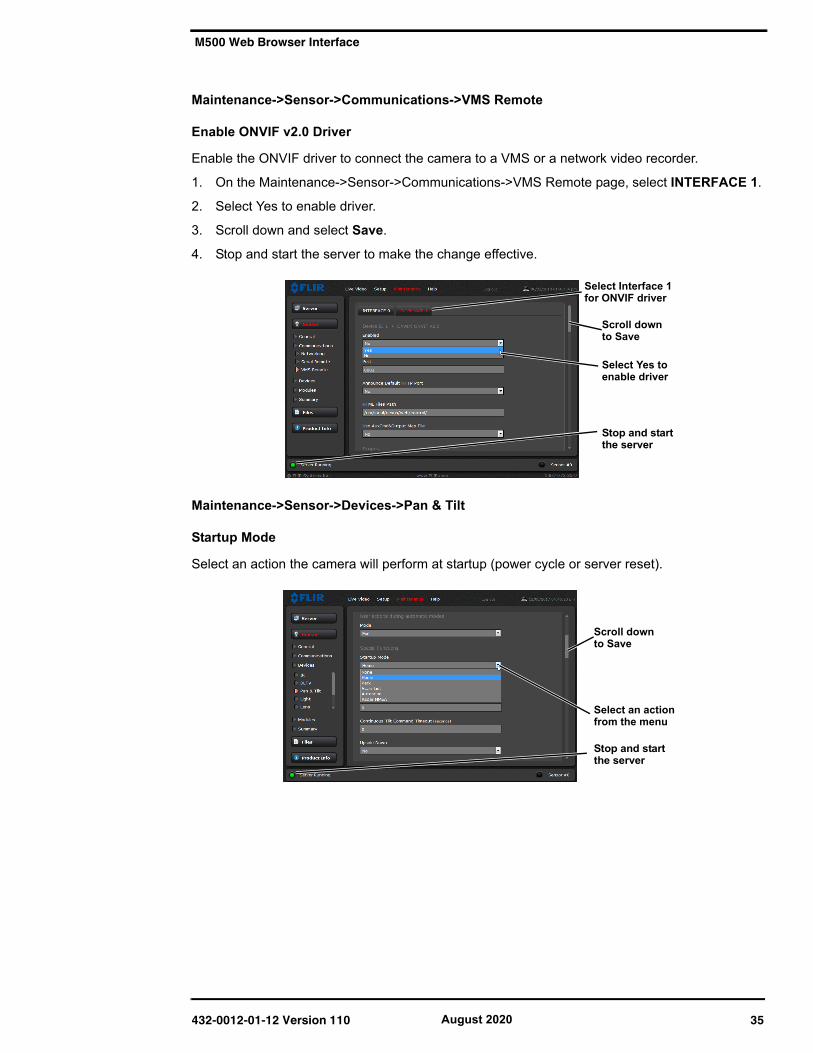
Maintenance->Sensor->Communications->VMS Remote
Enable ONVIF v2.0 Driver
Enable the ONVIF driver to connect the camera to a VMS or a network video recorder.
1. On the Maintenance->Sensor->Communications->VMS Remote page, select INTERFACE 1.
2. Select Yes to enable driver.
3. Scroll down and select Save.
4. Stop and start the server to make the change effective.
Maintenance->Sensor->Devices->Pan & Tilt
Startup Mode
Select an action the camera will perform at startup (power cycle or server reset).
Scroll down to Save
Select Yes to enable driver
Stop and start
Select Interface 1for ONVIF driver
the server
Scroll down to Save
Select an actionfrom the menu
Stop and startthe server
432-0012-01-12 Version 110 35 August 2020
M500 Web Browser Interface
Azimuth and Elevation Offsets
After the camera is installed, the azimuth may be set to account for variations required during installation. The azimuth direction should be directly toward the front of the vessel; the Elevation Offset should be zero. The azimuth/elevation offset can also be set using the OSD menu.
Setting Park Position
The default park position is defined as 0° azimuth and -90° elevation. If a different park position is desired, adjust the Park position as follows:
1. On the Maintenance->Sensor->Devices->Pan & Tilt page, enter the new values for ParkPosition.
Scroll down
Azimuth Offset
to Save
to front of vessel
Elevation Offsetfrom horizontal
Stop and startthe server
Enter new
Scroll down to Save
park position
Stop and startthe server
432-0012-01-12 Version 110 36 August 2020
M500 Web Browser Interface
Changing Video OutputsThe M500 camera system has two cameras with different video streams which are then processed to provide multiple display formats and video resolutions. Use the following web pages to control these video streams and how they are affected by Active Camera selections from the JCU II.
Maintenance->Sensor->Devices• Sensor -> Devices->IR, Aspect Ratio—select either 4:3 or 16:9 video
• Sensor -> Devices->DLTV—16:9 video
These video streams are provided unchanged as inputs to VIDMUX.
Maintenance->Sensor->Devices->Video Matrix
Scroll down to select how the Active Camera selection will affect each video Output (HDSDI, SD, or LiveView). Each video output stream can be set to the Active Camera, Secondary Camera, or to always display one or the other of the cameras.
Note: The IP video output streams can not be changed except by the initial selection above in Maintenance-> Sensor->Devices->IR or DLTV.
Additional display resolution settings can be made for the standard video (SD) and the LiveView video streams.
• Sensor -> Devices->Video Matrix Output 1 - SD Analog is processed as either NTSCLetter Box 720x360 (cropped top and bottom), NTSC Center Box 720x480 (full data), PALLetter Box 720x432 (cropped top and bottom), or PAL Center Box 720x576 (full data).
• Sensor -> Devices->Video Matrix Output 2 - LiveView (Live Video web page) is outputunchanged.
432-0012-01-12 Version 110 37 August 2020
M500 Web Browser Interface
Maintenance->Sensor->Modules->Video
VIDEO 0 is the daylight camera (DLTV) video stream, VIDEO 2, shown above and at the right, is the infrared camera video stream, and VIDEO 4 is the video stream shown on the Live Video web page.
• VIDEO 0 and VIDEO 2 Video Settings Image Size
• VIDEO 4 Video Settings Image Size
432-0012-01-12 Version 110 38 August 2020
M500 Web Browser Interface
Maintenance->Sensor->Modules->Radar Interface
Geo-Referencing of the SensorsThe Camera Server and the Radar Server can each have a Georeference location. When the camera is installed on a vessel, the location information can come from a GPS and gyrocompass and the information is available as NMEA data directly from those devices or through the radar device.
Maintenance->Sensor->Modules->Georeference
The Camera Server can have a different Georeference location and heading than the Radar Server, but typically they are associated with each other, with an offset if they are in different locations on a larger ship. It is recommended that the Radar Server is configured to receive the live location information, and the Camera Server Georeference can be associated with the Radar Server Georeference.
432-0012-01-12 Version 110 39 August 2020
M500 Web Browser Interface
Software UpdateWhen software updates become available, use the Software Update field to load the update to the camera. The update typically comes with a pre-update file (update-prep.sh) and an update file (for example, marlin-v2.1.1.swu.sh). Contact the FLIR dealer where you purchased the camera for additional information, or contact FLIR directly.
Maintenance->Files->Firmware
Accessing the JCU II Web InterfaceThe JCU II communicates through the Ethernet IP protocol just like the M500 camera does.
Changing the IP Address of the JCU IIOn the JCU II, the IP address is displayed by pressing the COLOR button and pushing the joystick forward at the same time. The IP addresses of the JCU II and the camera are displayed for 3 seconds and then the display returns to its state before the IP request was made.
On networks with specific requirements, you may need to assign the JCU II a static IP address. Do this using steps similar to the way you changed the camera IP address:
1. Determine the JCU II IP address by pressing theCOLOR button and pushing the joystick forwardat the same time. The IP address is shown onthe JCU II screen.
2. Type the JCU II IP address into the address barof the browser adding /index.html.for example: http://192.168.250.110/index.htmlThe JCU II Web page is shown, with a picture ofthe JCU II.
3. For Network Addressing, select Static.
4. Enter the new value in the IP field. The Network Mask should fill in automatically(255.255.255.0).
5. Click Save to save the changes and exit the Web page.
Click to stop server. The server must be stopped to upload or download any files.
432-0012-01-12 Version 110 40 August 2020
Enabling Universal Plug and Play (UPnP)
Enabling Universal Plug and Play (UPnP)In order to use the Web interface, the PC may need to be set up to use Universal Plug and Play (UPnP), which may not be active.
UPnP is typically not active on older computers using Windows XP but can be activated by following the steps outlined here.
Note: The JCU II will display on the PC network only when the PC is on the same network as the camera. If the PC is not configured with a static IP address, the UPnP icons will not display.
UPnP OverviewUPnP is a set of networking protocols that allows devices on a network to connect automatically, without the need for configuration by a network expert, thus simplifying the implementation of networks and the installation of computer components. A UPnP compatible device from any vendor can dynamically join a network, obtain an IP address, announce its name, convey its capabilities upon request, and learn about the presence and capabilities of other devices.
UPnP devices are plug-and-play in that when connected to a network they automatically announce information about themselves and supported device and services types, enabling clients that recognize those types to immediately begin using the device.
M500 cameras and JCU IIs are UPnP devices so they broadcast their presence on the network. A PC configured to accept UPnP broadcasts will show all UPnP devices discovered under My Network Places.
Enabling the UPnP User InterfaceIn some cases, Windows will discover UPnP devices and provide its own user interface to control them. Windows Vista and Windows 7 automatically detect network devices in the Network page. If UPnP devices are hidden, a prompt at the top of the screen will ask to display hidden devices.
With Windows XP, install the optional user interface (UI) component using the steps below. This UI component Web page a balloon tip for newly discovered devices and places an icon for each device in the My Network Places folder. To enable the UPnP UI, follow these steps:
1. Click Start, click Control Panel, and then click Add or Remove Programs.
2. In the Add or Remove Programs dialog box, click Add/Remove Windows Components on theleft side.
3. In the Windows Components Wizard, click Networking Services and then click Details.
432-0012-01-12 Version 110 41 August 2020
Enabling Universal Plug and Play (UPnP)
4. Select the Universal Plug and Play check box.
5. Click OK, and then click Next in the Windows Components Wizard. The Windows XPinstallation CD may be required.
See if any UPnP-enabled devices exist on your network by opening My Network Places. If there are UPnP devices on the local network, they will appear here with a generic icon based on the device type. In the future when a UPnP device is installed on the network, a notifying icon will appear briefly in the System Tray. When you see this icon, go to My Network Places to view the new device. Double-click on the icon to bring up the Web page.
432-0012-01-12 Version 110 42 August 2020
FLIR Systems, Inc.CS World HeadquartersFLIR Systems, Inc.6769 Hollister Ave.Goleta, CA 93117USA
The following Mechanical Interface Control Documents detail the outline and mounting for the M500 systems. These documents are provided for reference only. You should consult your local sales representative or application engineer to obtain current ICD information. Also, the Thermal Imaging Camera Data Sheet available from the website contains important mechanical interface data as well.
Figure A-1: M500 Top Down Riser Installation—Ball up
Socket Head Cap Screw with locking patchM6 X 1.0Length: 16 mm316 Stainless Steel6 placesApply corrosion inhibitor (USS TEF-GEL)Torque to 4.5 N-m (3.3 lb-ft)
AS568-436 EPDM O-Ring[5.85in ID x .275in DIA][49mm ID x 7mm DIA]AS568-444 EPDM O-Ring[7.72in ID x .275in DIA][96mm ID x 7mm DIA]
M500 Weight: <14 kg (31 lb)
Cable Port
Washer M6316 Stainless Steel
Mounting holes per customer supplied hardware6 Places
Customer decking, orother structuremaximum deck thickness for right angled cables withoutTop Down Riser: 10 mm
Gasket, Top Down Riser
Top Down Riser KitFLIR PN 4141973Highly recommendedfor installations onto metal surfaces
Fasteners between Top Down Riser and mounting surface to be supplied by the installer.
WarningDo not bottom fasteners in base.Bolt length not to exceed 6 mm into base.Electronics will be damaged by base penetrationBolt torque not to exceed 4.5 N-m (3.3 lb-ft).
6 places
Non-standard paint NoticeA. Secondary painting of the camera puts the warranty at risk. A change in paint is a change in design which may affect camera performance and reliability.
B. Paint color can significantly affect camera internal temperature. Darker colors generally absorb heat to a greater degree compared to light colors. Internal camera temperatures affect performance and reliability.
C. Those who still choose to paint the camera, must ensure secondary paint does not block airflow around the FLIR logos. There are moisturebarrier, pressure relief valves under the lowerFLIR icons which require airflow pathways for proper function.
432-0012-01-12 Version 110 44August 2020
Socket Head Cap Screw with locking patchM6 X 1.0Length: 16 mm316 Stainless Steel6 placesApply corrosion inhibitor (USS TEF-GEL)Torque to 4.5 N-m (3.3 lb-ft)
AS568-436 EPDM O-Ring[5.85in ID x .275in DIA][49mm ID x 7mm DIA]AS568-444 EPDM O-Ring[7.72in ID x .275in DIA][96mm ID x 7mm DIA]
M500 Weight: <14 kg (31 lb)
Cable PortMounting holes per customer supplied hardware6 Places
Gasket, Top Down Riser
Top Down Riser FLIR PN 4141973Highly recommendedfor installations onto metal surfaces
Fasteners between Top Down Riser and mounting surface to be supplied by the installer.
WarningDo not bottom fasteners in base.Bolt length not to exceed 6 mm into base.Electronics will be damaged by base penetrationBolt torque not to exceed 9.5N-m (7 lb-ft).
6 places
Washer M6316 Stainless Steel6 places
Figure A-2: M500 Top Down Riser Installation—Ball down
432-0012-01-12 Version 110 45August 2020
TABLE A.1 Analog Video and Serial Cable PinoutPin # Signal Name Wire Color
1 Factory TX-P GREEN
2 Factory TX-N GREEN/WHITE
3 ANALOG VIDEO OUT RG179
4 ANALOG VIDEO RETURN NATURAL
5 NMEA RX-N BROWN/WHITE
6 NMEA RX-P BROWN
7 NMEA TX-P BLUE
8 Factory RX-N ORANGE/WHITE
9 Factory RX-P ORANGE
10 NMEA SHIELD DRAIN
11 Factory SHIELD DRAIN
12 NMEA TX-N BLUE/WHITE
TABLE A.2 Ethernet Cable PinoutP1
Pin # Signal Name Wire Color P2Pin #
1 TXRX A+ ORANGE/WHITE 1
2 TXRX A- ORANGE 2
3 TXRX C+ DC+ BLUE 4
4 TXRX C- DC+ BLUE/WHITE 5
5 TXRX B+ GREEN/WHITE 3
6 TXRX B- GREEN 6
7 TXRX D+ DC- BROWN/WHITE 7
8 TXRX D- DC- BROWN 8
9 NA NA
10 DRAIN DRAIN SHELL
NMEA and Factory Test
F-type connector
Figure A-3: Analog Video and Serial CablePIN 1
PIN 2
PIN 3
PIN 4 PIN 5
PIN 6
PIN 7PIN 8
PIN 9
PIN 10
PIN 11
PIN 12
serial interface
Figure A-4: Ethernet Cable
P1
PIN 2
PIN 1
PIN 9
PIN 8
PIN 7
PIN 6PIN 5
PIN 10
PIN 3PIN 4
P2
RJ45 connector pinout in accordance with 802.3af Standard B
TABLE A.3 Power Cable Pinout
Signal Name Wire Color
BATT + RED
BATT - BLACK
CHASSIS GROUND DRAIN
432-0012-01-12 Version 110 46August 2020
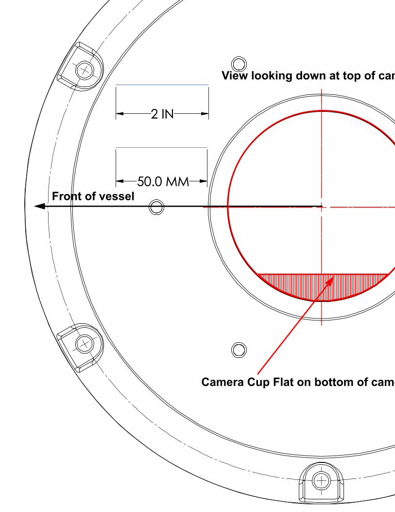
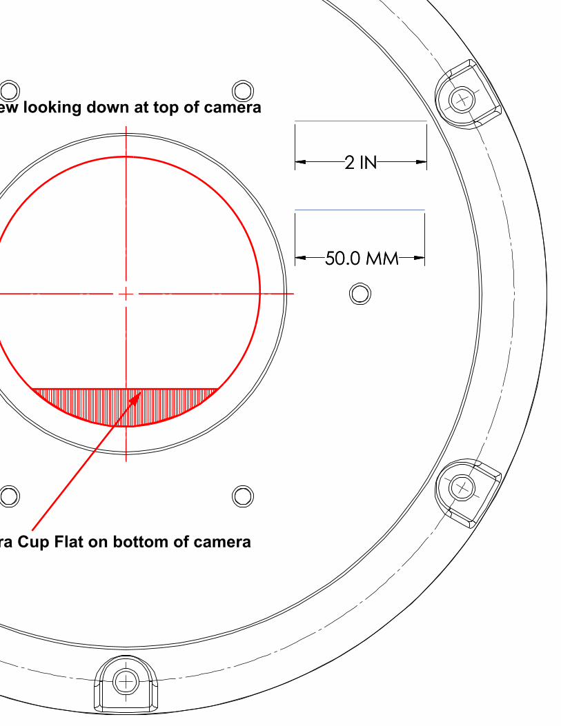
M500 Top Down Riser Installation Template
M500 Top Down Riser Installation TemplateThe following four pages provide a mounting template for the M500 camera using the top down riser which can be printed on a standard printer using either 8.5x11 or A4 paper. See “M500 Riser Installation Document” on page 55. for dimensions.
1. Ensure printer margins are set to zero and scale is 100%.
2. After printing verify the scale dimensions of the key on each page.
3. Align the center cross on the sheets to get a full 13 in. by 13 in. template.
Figure A-5: HD-SDI Cable
BNC connectors (2)
HD/SDI Isolation Transformer
BNC connectors (2)
refer to the latest released ICDfor installation requirements
to display Input from camera
432-0012-01-12 Version 110 47August 2020
50.0 MM
2 IN
50.0 MM
2 IN
Front of vessel
Camera Cup Flat on bottom of camera
View looking down at top of camera
50.0 MM
2 IN
50.0 MM
2 IN
MMMM
Camera Cup Flat on bottom of camera
View looking down at top of camera
50.0 MM
2 IN
50.0 MM
2 IN
Front of vessel
Camera Cup Flat on bottom of camera
View looking down at top of camera
50.0 MM
2 IN
50.0 MM
2 IN
MMMM
Camera Cup Flat on bottom of camera
View looking down at top of camera
M500 Installation Guide
-01-12, version 110 August 2020 52
9.61244.2
O-Ring used for sealing system to mounting structure.Stand alone unit meets IPx6 sealing specification.Minimum mounting surface flatness of 1.5mm [0.060in]over system diameter required for o-ring use. Whenmounting to irregular surfaces, use of bedding compoundis recommended.
ty.
Clearance required for free motion of system.9.61244
Clearance required for fre
M500 Interface Control Document Sheet 1
All dimensions are in mm and (inches)
432-0012
Appendix 1 Mechanical ICD Reference
Spotlight
InfraredCamera
VIsible Camera
AS568A-436 EPDM O-Ring [5.85in ID x .275in DIA]149mm ID x 7mm DIA
AS658A-444 EPDM O-Ring[7.72in ID x .275in DIA]196mm ID x 7mm DIA
7.09180.0 bolt circle
8.86225.0 min base plate diameter
for effective o-ring seal
Cable port dimensions depend on Mounting solution and cable type.
Warranty void if screws removed
HD/SDI BNC connector
Ethernet connector
Power connector
Analog video and serial connector
6X M6X1.0 10
Use Loctite 262 with all metal to metal threaded connections that do not have locking patches.
WarningDo not bottom fasteners in base.Bolt length not to exceed 6mm into base.Electronics will be damaged by base penetration - voiding warranBolt torque not to exceed 4.5 N-m (3.3 lb-ft).
Clearance required for free motion of system.
5.19131.8
potlight Clearance required
12.37314.2
9.29
236.0
10.75273.1
5.14
130.6
5.89149.7
15.70398.7
M500 Installation Guide
-01-12, version 110 August 2020 53
Joystick Control Unit Interface Control Document Sheet 1
3.0377.0
5.06
128.5
WITH CABLE INSTALLED, TURN NUT1/4 TURN BEYOND HAND TIGHT.
GLAND SEAL DESIGNED FOR USE WITH DOUBLE SHIELDED CAT 5 ETHERNET CABLE. USE OF SINGL SHIELDED CABLE MAY REQUITE THE USE OF ADDITIONAL SEALENT SUCH AS SILICON OR RTV TO ENSURE SEALING OF ENCLOSURE
INSERT NETWORK CABLE RJ45 THROUGH GLAND NUT AND SEAL BEFORE INSTALLINGET. IP64 RATED BEHIND GASKET.
All dimensions are in mm and (inches)
432-0012
Appendix 1 Mechanical ICD Reference
3.5890.8
5.62142.8
3.3284.2
IP66 RATED ABOVE GASK
3.0577.5
2.4361.8
APPLY ADHESIVE SIDE OF GASKET TO JCU BODY.
MOUNTING PANEL THICKNESS RANGE 1.6-45 [0.036-1.750].WHEN MOUNTING TO PANEL LESS THAN 6.3 [0.25] REVERSE PADDLES.
DURING INITIAL TIGHTENING, ENSURE MOUNTING TABS ON SCREWS SWING FREE OF REAR OUSING.
WITH TABS RUN UP AGAINST REAR OF INSTRUMENT PANEL, TIGHTNE 1/4 - 1/2 TURN BEYOND HAND TIGHT.
M500 Installation Guide
-01-12, version 110 August 2020 54
Maritime/Tracker Joystick Control Unit Interface Control Document Sheet 1
2.00IN
50MM
IMPORTANT NOTE:
PAPER SIZE: 11x17inTEMPLATE SHOULD PRINT 1:1
DUE TO VARIATION IN SOFTWARE ANDPRINTER, PLEASE VERIFY SCALE BELOWBEFORE MODIFIYING MOUNTING SURFACE.
2.00IN
50MM
Joystick Control Unit Interface Control Document Sheet 2
All dimensions are in mm and (inches)
432-0012
Appendix 1
Appendix 1Appendix 1
.256.4
3.10±.0578.7±1.3CUTOUT
3.5690.4
OUTSIDEOF JCU
5.10±.05129.5±1.3CUTOUT
5.57141.4
OUTSIDEOF JCU
4.85123.2
OPTIONALDRILL GUIDE
2.8572.4
OPTIONALDRILL GUIDE
CORNERS SHALLBE SHARP.
M500 Installation Guide
-01-12, version 110 August 2020 55
6X .32
8.2 Riser Clearance HolesRecommend: M8 socket head cap screws, or5/16" - 18 socket head cap screws, or5/16" - 18 hex head sheet metal screwsType and length dependant on mounting surface316 stainless steelApply thread locker (Loctite 262 or equivalent)
4.79121.6 Riser cable clearance hole
Recommended deck port: 30.0 [1.18] min130.0 [5.12] max