Page 1
For the very latest specifications visit www.aeroflex.com
4400
Highlights
• All major mobile communication standards
• Remote control through GPIB, LAN, USB
• Options for DC power supply and DC current measurements
• Parallel testing of TX, RX and Audio
Figure 1: 4403 Mobile Phone Tester – the ideal tool forservice centres and the repair loop in production
The 4400 Mobile Phone Tester Series is a leading-edge
product and a good example of Aeroflex's expertise in RF test
and measurement. The instruments of the 4400 Series have
been designed to meet the needs of manufacturing, quality
assurance, and engineering facilities as well as the
requirements in service factories and repair sites. Aeroflex
fulfills these requirements with two different versions of the
4400; the 4403 for service applications and the 4405 for the
production environment.
Unless indicated otherwise, all information in this data sheet
relates to both the 4403 and the 4405 Mobile Phone Testers.
Improving Manufacturing Throughput
In manufacturing and production, accuracy is a key factor.
Therefore the 4405 Mobile Phone Tester provides
exceptional precision, see for example the Voltage Standing
Wave Ratio (VSWR). In addition to this outstanding accuracy,
the 4405 offers high measurement speed and stability, which
makes the 4405 the first choice for production and
manufacturing.
With the remote control possibility via the IEEE/IEC bus
(GPIB), the 4400 will be easily integrated in every production
line. Aeroflex's experienced support personnel helps
manufacturers all over the world to integrate the 4400 into
new and existing production lines.
Mobile Phone Repair from Incoming Inspection to Calibration and Alignment
Measurement speed and accuracy of the 4403 Mobile Phone
Tester fulfill the needs of the service environment to calibrate
and align a mobile phone and then perform a final test. These
final tests are different and predefined by major mobile phone
manufacturers, and the 4400 Series has been approved for
service by all of them.
Today the 4403 Mobile Phone Tester supports and provides
solutions for all major mobile communication technologies.
With its user-friendly menu concept and graphical user
interface, the 4403 provides quick access to all the
measurements and their results. The menus are easy to read
and follow the same concept across all standards to keep
training time to a minimum.
Mobile Phone Tester Series
Page 2
Measurements cannot only be performed in manual mode but also
under remote control. The 7310 Lector and Scriptor family of test
automation programs facilitates easy-to-use tests; these are started
with very few mouse clicks and return a simple Pass or Fail verdict along
with more technical details. See the Lector and Scriptor info sheet for
more details.
The 4400 Series is approved for service by major mobile phone
vendors. These provide special software to align and calibrate the
phone. In most cases the vendors adapt their control software to the
4400, making use of the remote control capabilities of Aeroflex's testers.
Research and Development
Engineering and R&D facilities such as design houses require
measurement equipment which is easy to use, and which provides high
accuracy. With the 4400 Mobile Phone Tester Series, Aeroflex offers two
instruments with the same functionality but different performance,
leaving the choice of accuracy to the customer.
SPECIFICATION
Specifications valid after 60 minutes warm-up time at ambient
temperature, specified environmental conditions and typical
measurement range, within a period of one year after calibration.
The published accuracies are determined in accordance with GUM
(Guide to the Expression of Uncertainty in Measurement) and EA
(European Co-operation for Accreditation) application document
EA4/02: "Expressions of the Uncertainty of Measurements in
Calibration".
BASIC RF DATA
Two independent synthesizers for RX and TX measurements.
Frequency Range
430 to 500 MHz(1)
800 to 1000 MHz
1700 to 2300 MHz
Additional frequency range with the 1209 Downconverter(2)
529.6 to 729.6 MHz
600.0 to 800.0 MHz
1564.8 to 1764.8 MHz
2329.6 to 2529.6 MHz
2400.0 to 2600.0 MHz
Frequency Resolution
10 Hz
Frequency and Level Settling Time
350 ms
RF In/Out
N-type female connector
Input/output Impedance
50 Ω
1) Not available with WCDMA and TD-SCDMA(2) With 1209 Downconverter. Different input and output level ranges apply, see
separate data sheet for the 1209 Downconverter.(3) If RX signal >–32 dBm and TX signal >10 dBm
VSWR
4403 1.2
4405 1.15(3), 1.2
Attenuation of Harmonics up to 4 GHz (f0 = 800 to 1000 and 1700 to
2000 MHz)
>40 dB
Attenuation of Non-Harmonics up to 4 GHz at > 5 kHz from Carrier
>43 dB
TCXO FREQUENCY BASE
Temperature Characteristic
1 x 10⁻⁶ max.
Aging Characteristic
1 x 10⁻⁶ max./year (at +25°C ±2°C)
OCXO FREQUENCY BASE (OPTION)
Temperature Characteristic
5 x 10⁻⁸ max.
Aging Characteristic
1 x 10⁻⁷ max./year
EXTERNAL SYNCHRONIZATION INPUT
Input level
0 to +15 dBm
Impedance
50 Ω
Frequency
5, 10, 13 MHz (autodetection)
GENERAL DATA
Control Interfaces
IEEE 488.2 (GPIB)
LAN (RJ-45, TCP/IP)
USB type A (two on the front, two on the back, for USB flash drive, keyboard and mouse connection)
USB type B, for remote control
VGA
Mains Power Supply
94 to 132 V AC
187 to 264 V AC
Power Consumption
Max. 140 W
Operating Temperature
+5°C up to +45°C
Relative Humidity
<80%
H x W x L
202 x 401 x 431 mm (8 x 15.8 x 17”)
Weight
10.5 kg (without options) (23 lbs.)
Delivery Includes
Mains cable
USB memory stick
Getting started guide
User’s guides (CD)
Calibration report
2
Page 3
RAPID!
Application programming environment
RAPID! = Run Application Programs with Integrated Development
environment.
RAPID!
Programming language (a modern structured BASIC dialect)
Programming environment
Input/Output Control from RAPID! Programs
GPIB
RS-232
Parallel port (printer)
Floppy and hard disk access
Screen (text-based)
Keyboard, incl. bar code reader support
Elements for Structured Programming
Global and local variables
Functions, subroutines
Libraries
Elements for Event-Driven Programming
Keyboard events
SCPI events
External interface events
Other Programming Features
Direct access to SCPI command set,to control the 4400 and collect
measurement results for postprocessing
Information hiding (program files can be protected against reading by the
user)
Scripting (to create or change mobile tests easily and efficiently)
Functions of Built-In Programming Environment
File manager
Editor (multiple files)
Runtime I/O screen
Debug screen, display of variables contents
Figure 2: The 1209 Downconverter is an optional frequencyextension for Bluetooth, WLAN, GPS tests and Mobile TV
standards.
GENERAL OPTIONSAeroflex provides additional options for the 4400 Mobile Phone Tester
Series, facilitating tests of a mobile phone under various
conditions or against special requirements.
Figure 3. Start menu for evaluation tests provided in RAPID!
4470 Audio Option, 4471 Basic Codec Option and 4472 CodecExtension Option
With Aeroflex's 4400 Series and the Audio and Codec options, Aeroflex
provides complete testing solutions for mobile phones.
The Audio and Codec Options for the Aeroflex 4400 Series help to
measure and test the audio capabilities of the mobile phone,
ensuring its high quality. These options have been designed for the
particular needs of R&D, production, repair/service and quality
assurance.
The options can be easily integrated in the Aeroflex 4400 Mobile Phone
Tester, resulting in a compact RF and AF test system.
Audio
The Audio Option can test and evaluate the individual audio
components or the complete audio path of the mobile. There are
different ways to stimulate the mobile phone and to verify the audio
quality.
The generated signal can be fed into a loudspeaker to stimulate the
microphone; it can also stimulate the mobile at the headset input.
Using the codec options, you can transmit voice signals even over the
GSM traffic channel.
The audio signal from the mobile can be evaluated using either the
basic audio analyzer or the unique audio spectrum analyzer. A high
impedance AF input, an auxiliary input for the microphone and the
traffic channel (using the additional codec options) can be used as
sources for the analysis.
GSM Codecs
There are two different codec options for GSM available: the 4471 Basic
Codec Option for Full Rate (FR) speech and the 4472 Codec Extension
Option for Enhanced Full Rate (EFR). These codecs
supplement the audio measurements, allowing audio signals to be
generated and tested via the air interface.
3
Page 4
4481 AM Signal Generator Option
The AM Signal Generator allows the tuning of certain phones in
asynchronous (or non-call) mode. The modulation index and the
modulation signal can be varied to support some vendor-specific AM
suppression measurements.
4473 MS Power Supply Option
In production lines and service centres, mobile phone testing is
usually conducted using an external power supply. Now, Aeroflex helps
mobile manufacturers and service factories optimise their workspace,
instrument control and budget by integrating the power supply into the
Aeroflex 4400 Series.
Aeroflex’s MS Power Supply Option enhances the functionality of the
4400 Mobile Phone Tester Series by enabling engineers to eliminate the
external power supply. With this easy-to-use add-on, the
revolutionary 4400 supplies the mobile with DC power and tests RF and
audio, all from one instrument.
The option was developed in consultation with mobile phone
manufacturers and service centres with the aim of improving mobile
phone testing processes and environments.
This innovative testing option provides a number of benefits:
• Easier programming - The option employs remote control and
RAPID! integration based on SCPI and 4400 standards.
• Streamlined troubleshooting - Quick separation of handset and
power supply problems ensures faster problem resolution.
• Minimize space and cost
The MS Power Supply Option not only reduces installation and
maintenance costs but also saves money over time by reducing the
number of devices manufacturers and service centers need to hold.
The option’s simple-to-interpret graphical user interface, which
reduces both the need for training and the time taken on each test,
further enhances the cost savings.
• Multiple, simultaneous testing capabilities
The MS Power Supply Option can support GPRS applications
because it is able to feed currents for the transmission of at least
two time slots per frame. The number of time slots is limited only
by the current level in transmit mode.
• One-box solution
The MS Power Supply Option is shipped with a one-meter cable,
designed to plug simply and easily into the power supply socket on
the front panel of your 4400. The open-ended termination on this
cable provides free adaptation into an existing test system.
SPECIFICATIONS
OUTPUT VOLTAGE
Range
0 to 10 V
Resolution
50 mV
Accuracy (with constant current)
±20 mV
Maximum Output Current
Continuous (<4 V) 1 A
Continuous (≥4 V) 0.25 A
Peak (<1 ms, <4 V)
4 A
Peak (<1 ms, ≥4 V)
2 A
Ripple Noise (peak-to-peak)
100 mV/A
Proof Against Permanent Short-Circuit
Scope of supply
A power supply connection cable of one meter length with open ends
for free adaptation according to user needs is delivered with the option.
4
Page 5
For the very latest specifications visit www.aeroflex.com
4474 MS CURRENT MEASUREMENTOPTIONIn specific test stations at manufacturing lines and repair stations,
measurement of the current from the battery is a "must" in order to
identify any failure on the PCB (Printed Circuit Board). Quality
assurance measures the current in order to characterize standby and
talk times.
For this range of applications the 4400 plug-in option "MS Current
Measurement" substitutes an external current meter and measures
power and current, which the mobile drains from the battery. The user
can choose between a numerical measurement and a unique graphical
representation of the current versus time measurements. The current
changes dynamically as the mobile’s power amplifier generates the RF
bursts.
In addition the option provides a statistical evaluation for minimum,
maximum, average and peak value regarding the selected duration time.
The duration of the graphical representation is 4.615 ms which enables
the user to analyze a complete GSM TDMA frame.
The 4474 MS Current Measurement Option is an extension of the 4473
MS Power Supply Option. To connect the 4400 with the mobile, a power
supply cable is delivered with the option. An open-ended
termination on this cable provides free adaptation into an existing test
system.
Both options extend the test application area of the 4400. The 4400 is
now able to supply the mobile under test, measures RF and audio
quality and the power consumption with one test instrument.
The benefits in brief:
• Integrated current meter, e.g. to identify short-circuit
situations, eases handling for the user
• The 4400 user can test RF, audio and power consumption with
one test instrument
• No additional external current meter necessary, this saves space in
test systems
• Power, peak current and average current measurements
possible
• Easy-to-read numerical measurement display
• Current vs. time measurements for the analysis of burst current
characteristics with selectable resolutions
• Statistical evaluation and overload detection
• Battery replacement
SPECIFICATIONS
MEASUREMENT
Range
0 to 400 mA or 0 to 4 A
Resolution (at 400 mA)
0.1 mA
Resolution (at 4 A)
1 mA
Accuracy
2%
Offset
±5 mA
Output Voltage Range
0 to 10 V
Recording Duration
4.615 ms (1 TDMA frame)
Resolution
960 points
Sample Rate
192 000 samples/sec
Connection Cable
A 0.5 meter long power supply connection cable with open ends for free
adaptation of user needs is delivered with the option.
5
Page 6
6
OPTIONS FOR WCDMA (UMTS) ANDHSDPAThe WCDMA offering on the 4400 consist of two main options, the
4466 WCDMA/UMTS Non-Call Mode Option and the 4467
WCDMA/UMTS Call Mode Option. These software options are based
upon the 4479 Baseband Processing Hardware.
4466 WCDMA Non-Call Mode Option
The Non-Call Mode Option, sometimes also known as asynchronous
mode or non-signaling mode, offers all the functionality required to
tune a WCDMA mobile phone in a production or high level service
environment. It offers all the functions necessary to generate and
analyze a WCDMA signal. This functionality is dedicated to the
alignment and calibration of the Printed Circuit Board (PCB) of a 3G
mobile phone; these two steps are necessary to guarantee that the
mobile phone's radio frequency parameters are within the limits
specified.
Typical tests include:
• Power measurements
• Modulation quality measurements
• Constellation display
• Code domain power measurements
• Spectrum measurements
• TX-RX sweep calibration
To tune the receiver of a 3G mobile phone the 4400 offers various
signals - a Continuous Wave (CW) signal, a Frequency Modulated (FM)
signal and the WCDMA-modulated signal.
There are more features available, like the power staircase
measurement or the zero-span-analyzer. The power staircase test has
been designed for specific measurements of the power changes; the
zero-span-analyzer can perform the same in a more flexible way and
displays power versus time, just as a spectrum analyzer does in zero-
span mode. These features can be used to display nearly all
signals which are generated within the frequency range of the 4400.
Overall the non-call mode functionality is mostly used through remote
control and in cooperation with service software controlling both the
tester and the device under test.
4467 WCDMA Call Mode Option
The call mode option of the 4400 is prepared for the requirements of a
final test. These tests are based on 3GPP/FDD Release '99 and ETSI
specification TS 134.121.
Call mode or signalling tests are necessary to test the behaviour of the
WCDMA (UMTS) mobile phone in a network, closer to the reality.
Therefore the 4400 acts as a Node B (WCDMA base station),
supporting the necessary signalling exchange.
All the relevant parameters, such as the configured downlink
channels, can be configured. The 4400 supports the required call
processing algorithm for call set up (mobile-terminated call,
mobile-originated call) and also for loopback mode on one of the
Reference Measurement Channels (RMC); these channels are
specified for transmitter and receiver testing.
The 4400 Mobile Phone Tester Series provides a long list of
transmitter measurements, which can be divided into modulation
quality, power, code domain and spectrum measurements with
additional reports from the phone. Receiver measurements are also
included. Fast testing on different frequency channels is supported with
the handover procedure to keep test time to a minimum.
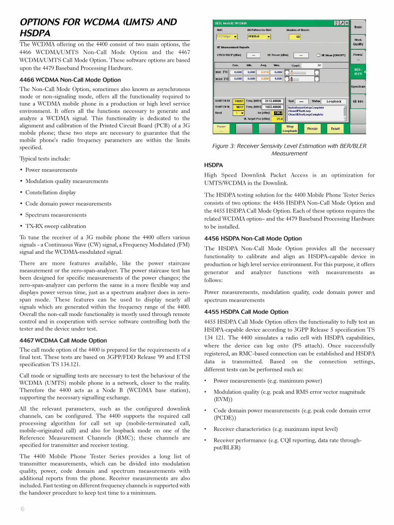
Figure 3: Receiver Sensivity Level Estimation with BER/BLERMeasurement
HSDPA
High Speed Downlink Packet Access is an optimization for
UMTS/WCDMA in the Downlink.
The HSDPA testing solution for the 4400 Mobile Phone Tester Series
consists of two options: the 4456 HSDPA Non-Call Mode Option and
the 4455 HSDPA Call Mode Option. Each of these options requires the
related WCDMA option– and the 4479 Baseband Processing Hardware
to be installed.
4456 HSDPA Non-Call Mode Option
The HSDPA Non-Call Mode Option provides all the necessary
functionality to calibrate and align an HSDPA-capable device in
production or high level service environment. For this purpose, it offers
generator and analyzer functions with measurements as
follows:
Power measurements, modulation quality, code domain power and
spectrum measurements
4455 HSDPA Call Mode Option
4455 HSDPA Call Mode Option offers the functionality to fully test an
HSDPA-capable device according to 3GPP Release 5 specification TS
134 121. The 4400 simulates a radio cell with HSDPA capabilities,
where the device can log onto (PS attach). Once successfully
registered, an RMC-based connection can be established and HSDPA
data is transmitted. Based on the connection settings,
different tests can be performed such as:
• Power measurements (e.g. maximum power)
• Modulation quality (e.g. peak and RMS error vector magnitude
(EVM))
• Code domain power measurements (e.g. peak code domain error
(PCDE))
• Receiver characteristics (e.g. maximum input level)
• Receiver performance (e.g. CQI reporting, data rate through-
put/BLER)
Page 7
For the very latest specifications visit www.aeroflex.com
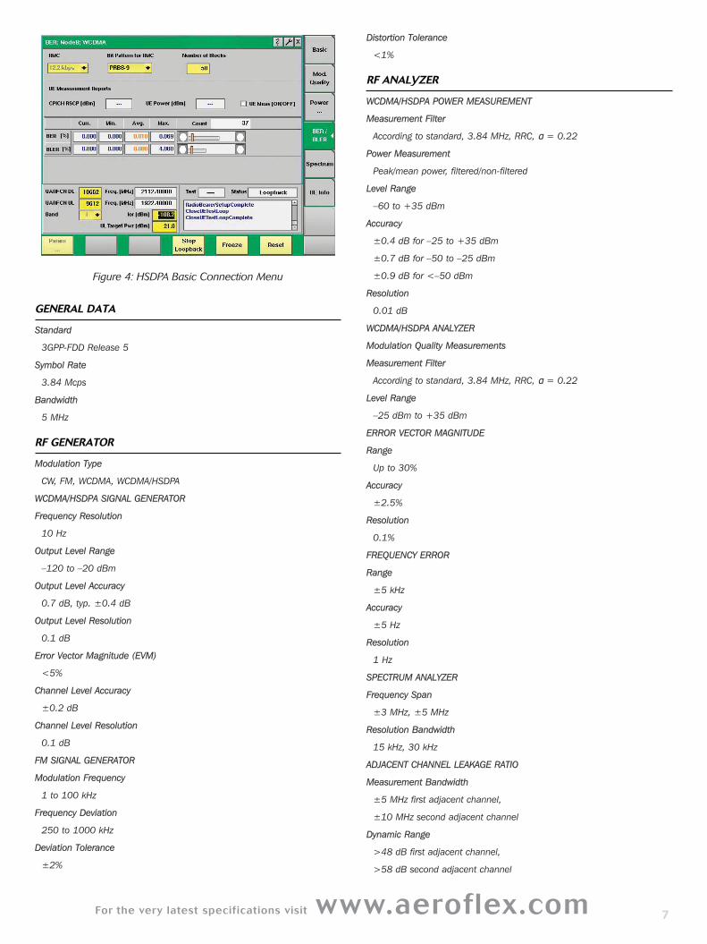
Figure 4: HSDPA Basic Connection Menu
GENERAL DATA
Standard
3GPP-FDD Release 5
Symbol Rate
3.84 Mcps
Bandwidth
5 MHz
RF GENERATOR
Modulation Type
CW, FM, WCDMA, WCDMA/HSDPA
WCDMA/HSDPA SIGNAL GENERATOR
Frequency Resolution
10 Hz
Output Level Range
–120 to –20 dBm
Output Level Accuracy
0.7 dB, typ. ±0.4 dB
Output Level Resolution
0.1 dB
Error Vector Magnitude (EVM)
<5%
Channel Level Accuracy
±0.2 dB
Channel Level Resolution
0.1 dB
FM SIGNAL GENERATOR
Modulation Frequency
1 to 100 kHz
Frequency Deviation
250 to 1000 kHz
Deviation Tolerance
±2%
Distortion Tolerance
<1%
RF ANALYZER
WCDMA/HSDPA POWER MEASUREMENT
Measurement Filter
According to standard, 3.84 MHz, RRC, α = 0.22
Power Measurement
Peak/mean power, filtered/non-filtered
Level Range
–60 to +35 dBm
Accuracy
±0.4 dB for –25 to +35 dBm
±0.7 dB for –50 to –25 dBm
±0.9 dB for <–50 dBm
Resolution
0.01 dB
WCDMA/HSDPA ANALYZER
Modulation Quality Measurements
Measurement Filter
According to standard, 3.84 MHz, RRC, α = 0.22
Level Range
–25 dBm to +35 dBm
ERROR VECTOR MAGNITUDE
Range
Up to 30%
Accuracy
±2.5%
Resolution
0.1%
FREQUENCY ERROR
Range
±5 kHz
Accuracy
±5 Hz
Resolution
1 Hz
SPECTRUM ANALYZER
Frequency Span
±3 MHz, ±5 MHz
Resolution Bandwidth
15 kHz, 30 kHz
ADJACENT CHANNEL LEAKAGE RATIO
Measurement Bandwidth
±5 MHz first adjacent channel,
±10 MHz second adjacent channel
Dynamic Range
>48 dB first adjacent channel,
>58 dB second adjacent channel
7
Page 8
8
Display Range
80 dB
Resolution
0.1 dB
Occupied Bandwidth
Range
1 to 6 MHz
Accuracy
±100 Hz
Resolution
15 kHz
SPECTRUM EMISSION MASK
Measurement Filter
±2.515 to ±3.485 MHz 30 kHz Gaussian
±4 to ±12 MHz 1 MHz Gaussian
Dynamic range
±2.515 to ±3.485 MHz: >70 dB
±4 to ±12 MHz: >65 dB
Resolution
0.1 dB
NON-CALL MODE FUNCTIONS
WCDMA/HSDPA ANALYZER
Power Measurements
Peak power, mean power
Spectrum Measurements
Occupied bandwidth (OBW), adjacent channel power leakage ratio
(ACLR), spectrum emission mask (SEM)
Modulation Quality
Error vector magnitude (EVM), magnitude error, frequency error, phase
error, rho, I/Q offset, I/Q imbalance, constellation display
CODE DOMAIN MEASUREMENTS
Peak code domain error (PCDE), code domain power
POWER VS. TIME
Zero-span analyzer (flexible power vs. time measurements)
Sweep Time
1 to 85 ms1
Reference Level
–23 to 36 dBm
Filter
30 kHz, 100 kHz, 4.6848 MHz
GENERATOR
CW, FM and WCDMA signal151 ms for 4.6848 MHz filter
CALL MODE FUNCTIONS
WCDMA CALL PROCESSING
Supported Bands
Band I- 1920 to 1980 MHz (UL)
2110 to 2170 MHz (DL)
Band II- 1850 to 1910 MHz (UL)
1930 to 1990 MHz (DL)
Band III- 1710 to 1785 MHz (UL)
1805 to 1880 MHz (DL)
Band IV- 1710 to 1755 MHz (UL)
2110 to 2155 MHz (DL)
Band V- 824 to 849 MHz (UL)
869 to 894 MHz (DL)
Band VI-830 to 840 MHz (UL)
875 to 885 MHz (DL)
Band VIII-880 to 915 MHz (UL)
925 to 960 MHz (DL)
Band IX- 1749.9 to 1784.9 MHz (UL)
1844.9 to 1879.9 MHz (DL)
Band X- 1710 to 1770 MHz (UL)
2110 to 2170 MHz (DL)
Supported Procedures
Universal Routing Update (URA), mobile originated call, mobile
terminated call, call clearing by mobile and tester, inter-frequency
handover (channel change), inter-RAT handover (to GSM/GPRS/EDGE)
Reference Measurement Channels According to 3GPP TS 134121
RMC 12.2, 64, 144, 384 kbps
HSDPA Specific Reference Channels
H-Set 1 – 6 QPSK, 16QAM with AWGN and fading (PA3)
Transmitter Measurements
Peak and mean power
Min and max output power
Inner loop power control
Open loop power control
HS-DPCCH power
Spectrum Measurements
Occupied bandwidth (OBW)
Adjacent channel power leakage ratio (ACLR)
Spectrum emission mask (SEM)
Modulation Quality Measurements
Error vector magnitude (EVM)
Magnitude error
Frequency error
Phase error
Rho
I/Q offset
I/Q imbalance
Constellation display
Phase discontinuity
HSDPA: Error vector magnitude
Phase discontinuity
Relative code domain power
Relative code domain error
Code Domain Measurements
Peak code domain error (PCDE), code domain power
Receiver Measurements
BER/BLER measurements
UE Info with UE Measurement Report
HSDPA: Maximum throughput test
BLER
Demodulation of HS-DSCH
Reporting of channel quality indicator (CQI)
Page 9
For the very latest specifications visit www.aeroflex.com
OPTIONS FOR TD-SCDMATD-SCDMA (Time Division Synchronous CDMA) is a
third-generation wireless communications standard for China,
combining Time Division Multiplex Access (TDMA) technology
with a synchronous CDMA component.
Aeroflex's TD-SCDMA testing solution is based on the 4400 Series
Mobile Phone Tester, the 4450 TD-SCDMA Non-Call Mode Option,
the 4451 TD-SCDMA Call Mode Option and the 4479 Baseband
Processing Hardware.
4450 TD-SCDMA Non-Call Mode Option
The 4450 TD-SCDMA Non-Call Mode Option can be seen as a
combined signal analyzer and generator in one instrument used in
R&D, production and high level service environments.
The analyzer functionality provides the following features:
• Power measurements, such as channel, mean, peak, off-power
measurements
• Modulation quality measurements with measurements like Error
Vector
Magnitude (EVM RMS), frequency, magnitude and phase error
• Constellation display
• Code domain power measurements
• Spectrum measurements
Signals such as Continuous Wave (CW), burst and TD-SCDMA
together with QPSK modulation and various types of payload data
allow a flexible tuning of TD-SCDMA handset receivers.
4451 TD-SCDMA Call Mode Option
The Call Mode Option supports the functionality required for typical
tests on a TD-SCDMA mobile phone. These tests are based on the
3GPP/TDD Release ’99 and ETSI specification TS 134.122 (Low
Chip Rate – LCR).
The call processing is required to simulate a TD-SCDMA base
station and test the proper behaviour of the TD-SCDMA mobile
phone in a network. The 4400 in this way acts as a Node B
(TD-SCDMA base station), supporting the necessary signalling. All
the relevant parameters, such as the configured downlink channels,
can be configured. The 4400 supports the basic registration
procedure, as well as the required call processing for the call setup
(mobile-terminated and mobile-originated) and for the test loopback
mode on one of the Reference Measurement Channels (RMC); these
channels are specified for transmitter and receiver testing.
The 4400 Mobile Phone Tester Series provides a long list of
transmitter measurements, which can be divided into modulation
quality, power, code domain and spectrum measurements with
additional measurement reports from the mobile phone. Receiver
measurements are also included and supported. In order to support
fast testing on various frequency channels, handover procedures are
also included – this will keep measurement time to a minimum.
Figure 5: TD-SCDMA power measurements
Figure 6: Constellation Display
GENERAL DATA
Standard
3GPP-TDD
Symbol Rate
1.28 Mcp
Bandwidth
1.6 MHz
RF GENERATOR
Modulation type
CW, burst, TD-SCDMA downlink
TD-SCDMA SIGNAL GENERATOR
Frequency Range
800 to 1000 MHz
1700 to 2300 MHz
Frequency Resolution
1 Hz
9
Page 10
Output Level Range
–120 to –13 dBm
Output Level Accuracy
0.7 dB, typ. ±0.4 dB
Output Level Resolution
0.1 dB
Error Vector Magnitude (EVM)
<5%
Supported Physical Channels
P-CCPCH, S-CCPCH, PICH, DwPCH, FPACH, DPCH
Code Channel Level Range
Off, –30 to 0 dB to absolute level
Code Channel Level Accuracy
±0.2 dB (relative level)
Code Channel Level Resolution
0.1 dB
RF ANALYZER
TD-SCDMA POWER MEASUREMENTS
Measurement Filter
According to standard, 1.28, RRC, alpha = 0.22
Measurements
Channel power, peak/mean/off power, power on/off mask
Frequency Range
800 to 1000 MHz
1700 to 2300 MHz
Level Range
–60 to +35 dBm
Level Accuracy
±0.4 dB for high power (–25 to +35 dBm)
±0.7 dB for low power (–60 to –25 dBm)
±0.9 dB for <-60 dBm
Resolution
0.01 dB
MODULATION QUALITY MEASUREMENT
Measurement Filter
According to standard 1.6 MHz, RRC, alpha = 0.22
Frequency Range
800 to 1000 MHz
1700 to 2300 MHz
Level Range
–25 to +35 dBm
ERROR VECTOR MAGNITUDE (EVM)
Range
up to 30%
Accuracy
±2.5%
Resolution
0.1%
FREQUENCY ERROR
Range
±10 kHz
Accuracy
±10 Hz
Resolution
1 Hz
WAVEFORM QUALITY
Range
0.9 to 1.0
Accuracy
±0.002
Resolution
0.0001
SPECTRUM
Span
±1.2 MHz, ±2.4 MHz
Resolution Bandwidth
15 kHz, 30 kHz
ADJACENT CHANNEL LEAKAGE POWER RATIO (ACLR)
Measurement Bandwidth
±1.6 MHz, first adjacent channel
±3.2 MHz, second adjacent channel
Dynamic Range
>48 dB, first adjacent channel
>58 dB, second adjacent channel
Display Range
80 dB
Resolution
0.1 dB
OCCUPIED BANDWIDTH
Range
1 MHz to 4 MHz
Accuracy
±100 kHz
Resolution
15 kHz
SPECTRUM EMISSION MASK
Measurement Filter
±0.8 MHz to ±2.4 MHz 30 kHz Gaussian
±2.4 MHz to ±4 MHz 1 MHz Gaussian
Dynamic Range
±0.8 MHz to ±2.4 MHz >70 dB
±2.4 MHz to ±4 MHz >65 dB
Resolution
0.1 dB
10
Page 11
For the very latest specifications visit www.aeroflex.com
NON-CALL MODE FUNCTIONS
TD-SCDMA ANALYZER
Power Measurements
Channel power, peak/mean/off power, power on/off mask
Spectrum Measurements
Modulation spectrum
Occupied bandwidth (OBW)
Adjacent Channel leakage power ratio (ACLR)
Spectrum emission mask (SEM)
Modulation Quality
EVM, frequency error, magnitude error, phase error, I/Q offset, I/Q
imbalance, Rho
Code Domain Measurements
Peak code domain error (PCDE), code domain spectrum
GENERATOR
Signal Type
CW, burst, TD-SCDMA
Modulation
None, QPSK
Downlink Timeslots
1 to 6
Payload Data
PN9, PN15, PN23, all 0s, all 1s, 1010..., 1100..., 11110000,
1...10...0
Data Rate (Reference Measurement Channel – RMC)
12.2 kbps
CALL MODE FUNCTIONS
TD-SCDMA CALL PROCESSING
Supported Bands
1900 to 1920 MHz (UL & DL)
2010 to 2025 MHz (UL & DL)
1850 to 1910 MHz: (UL & DL)
1930 to 1990 MHz: (UL & DL)
1910 to 1930 MHz: (UL & DL)
Supported Procedures
Registration, mobile originated call, mobile terminated call, call
clearing by mobile and tester, inter-frequency handover (channel change)
Reference Measurement Channels according to 3GPP TS 34.122
RMC 12.2 kbps (single code and multicode)
RMC 64 kbps
Transmitter Measurements
Peak and mean power, min and max power, inner loop power control,
open loop power control, Transmit ON/OFF Time mask
Spectrum Measurements
Occupied bandwidth (OBW), adjacent channel power leakage ratio
(ACLR), spectrum emission mask (SEM)
Modulation Quality Measurements
Error vector magnitude (EVM), magnitude error, frequency error, phase
error, rho, I/Q offset, I/Q imbalance, constellation display
Code Domain Measurements
Peak code domain error (PCDE), code spectrum
Receiver Measurements
BER/BLER measurements
UE Info with UE Measurement Report
(e.g. UE power, P-CCPCH RSCP, path loss)
OPTIONS FOR CDMA2000The CDMA2000 system options for the 4400 Series enable users in
R&D, manufacturing and service to test subscriber terminals which are
based on the cdmaOne and CDMA2000 technologies. The 4447
CDMA2000 1xRTT Non-Call Mode Option supports asynchronous
measurements and the 4448 CDMA2000 1xRTT Call Mode Option
supports synchronous measurements, so the combination of the both
allow the user to perform alignment as well as functional testing of
terminals.
Supported features are:
• cdmaOne and CDMA2000 call processing including registration,
MS/BS originated call, MS/BS termination, handovers
• Fast power measurements including Min/Max power, open loop
power, gated power, closed loop power and access probe power
• Modulation quality measurements including waveform quality and
code domain measurements
• Receiver performance testing including receiver sensitivity and
dynamic range using the FER feature
• AM generation for calibration of terminals supporting ZIF (zero
intermediate frequency) based chipsets
The CDMA2000 System Option supports the following bands: 0-US
Cellular, 1-US PCS, 2-TACS, 3 JTACS, 4-Korean PCS, 5-NMT-450, 6
IMT 2000, 8-1800 MHz, and 9-900 MHz.
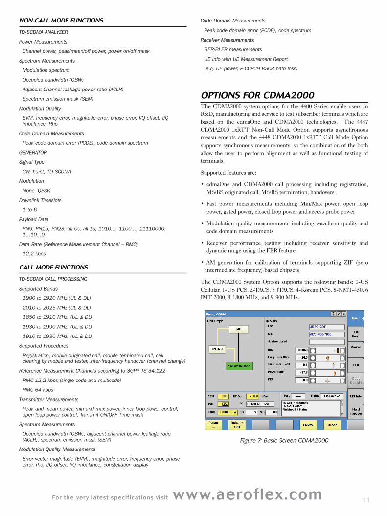
Figure 7: Basic Screen CDMA2000
11
Page 12
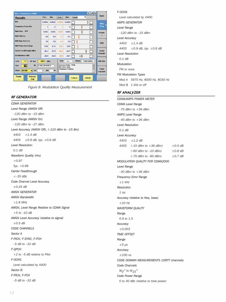
Figure 8: Modulation Quality Measurement
RF GENERATOR
CDMA GENERATOR
Level Range (AWGN Off)
–120 dBm to –15 dBm
Level Range (AWGN On)
–120 dBm to –27 dBm
Level Accuracy (AWGN Off), (–110 dBm to –15 Bm)
4403 ±1.4 dB
4405 ±0.9 dB, typ. ±0.6 dB
Level Resolution
0.1 dB
Waveform Quality (rho)
>0.97
Typ. >0.99
Carrier Feedthrough
<–35 dBc
Code Channel Level Accuracy
±0.25 dB
AWGN GENERATOR
AWGN Bandwidth
>1.8 MHz
AWGN, Level Range Relative to CDMA Signal
+5 to –10 dB
AWGN Level Accuracy (relative to signal)
±0.5 dB
CODE CHANNELS
Sector A
F-PICH, F-SYNC, F-FCH
–5 dB to –32 dB
F-QPCH
+2 to –5 dB relative to Pilot
F-OCNS
Level calculated by 4400
Sector B
F-PICH, F-FCH
–5 dB to –32 dB
F-OCNS
Level calculated by 4400
AMPS GENERATOR
Level Range
–120 dBm to –15 dBm
Level Accuracy
4403 ±1.4 dB
4405 ±0.9 dB, typ. ±0.6 dB
Level Resolution
0.1 dB
Modulation
FM or none
FM Modulation Types
Mod A 5970 Hz, 6000 Hz, 6030 Hz
Mod B 1 kHz or off
RF ANALYZER
CDMA/AMPS POWER METER
CDMA Level Range
–70 dBm to +36 dBm
AMPS Level Range
–40 dBm to +36 dBm
Level Resolution
0.1 dB
Level Accuracy
4403 ±1.2 dB
4405 (–10 dBm to +36 dBm) ±0.5 dB
(–60 dBm to –10 dBm) ±0.6 dB
(–70 dBm to –60 dBm) ±0.7 dB
MODULATION QUALITY FOR CDMA2000
Level Range
–30 dBm to +36 dBm
Frequency Error Range
±1 kHz
Resolution
1 Hz
Accuracy (relative to freq. base)
±10 Hz
WAVEFORM QUALITY
Range
0.9 to 1.0
Accuracy
±0.003
TIME OFFSET
Range
±5 µs
Accuracy
±100 ns
CODE DOMAIN MEASUREMENTS (1XRTT channels)
Code Channels
W016 to W15
16
Code Power Range
0 to 40 dBc (relative to total power)
12
Page 13
For the very latest specifications visit www.aeroflex.com
Code Power Resolution
0.1 dB
Code Power Accuracy
±0.1 dB
Number of Code Channels
1 to 6
Timing Range
0 to 200 ns
Timing Resolution
1 ns
Timing Accuracy
±2 ns
Code Domain Power Range
±3.75 dB (relative to reverse pilot)
Code Domain Power Resolution
0.1 dB
Code Domain Power Accuracy
±0.1 dB
MODULATION SPECTRUM
Display Range
80 dB
Resolution Bandwidth
5 kHz, 10 kHz, 30 kHz
Span (selectable)
±2.5 MHz, ±1.25 MHz, ±500 kHz
ACPM
Display Range
80 dB
Frequencies According to IS-98D up to 2.5 MHz from Centre Frequency
Measurements
Spectrum due to modulation
MODULATION ANALYZER FOR AMPS
Level Range
–15 dBm to +36 dBm
Frequency Error Range
±5 kHz
Resolution
1 Hz
Accuracy (relative to freq. base)
±20 Hz
Deviation Range
0 to 30 kHz
Deviation Resolution
1 Hz
Deviation Accuracy
±5%
Audio Deviation Filter
300 kHz
SAT Frequency Range
±5 Hz
ST Frequency Range
±5 Hz
SAT & ST Frequency Resolution
1 Hz
SAT & ST Frequency Accuracy
±0.1 Hz
NON-CALL MODE FUNCTIONS
CDMA GENERATOR
Signal type
Continuous
Modulation
None, BPSK/QPSK
User-definable parameters for CDMA cell simulation
SID, NID, MCC, MNC, PN offset
CDMA ANALYZER
Supported Signal Types
OQPSK, HPSK
Supported transmitter measurements power gated power, waveform quality, code domain
AMPS GENERATOR
Signal Types
Continuous
Modulation
None, FM
AMPS ANALYZER
Support Signal Types
FM
Supported Transmitter Measurements
Power, frequency error, SAT & ST frequency and deviation, audio devia-tion, SINAD – requires Audio Option
CALL MODE FUNCTIONS
CDMA2000 CALL PROCESSING
Supported CDMA2000 bands
band 0 – US cellular (ch 1 to 1023)
band 1 – PCS band (ch 1 to 1199)
band 2 – TACS band (ch 1-1000, 1329-2047)
band 3 – JTACS band
band 4 - Korean PCS (ch 1 to 599)
band 5 – NMT-450
band 6 – IMT-2000 (ch 1 to 1199)
band 8 – 1800 MHz (ch 1 to 1499)
band 9 – 900 MHz (ch 1 to 699)
Supported Procedures
Registrations, mobile-originated call, mobile-terminated call, intracell handover, cross-band handover, call clearing by MS, call clearing by4400
SPECIAL FUNCTIONS
Call State Diagram
MS Information Display
Mobile ID Number (MIN), Equipment Serial Number (ESN), IMSI (class 0and 1), type, slot class, slot index, power class, transmit mode, digitsdialed
Common Control Channel Parameters
SID, NID, MCC, MNC, PN Offset
Access Channel Parameters
Nominal power, initial power, power step, number steps, request
13
Page 14
sequences, response sequences, timeout, preamble length
Paging Rate
Full
Radio Configuration Combinations
F-RC1/R-RC1, F-RC2/R-RC2, F-RC3/R-RC3, F-RC4/R-RC3, F-RC5/R-RC4
Service Options
1 – 9.6 kbps voice, 2 – 9.6 kbps loopback, 3 – EVRC voice, 9 – 14.4kbps loopback, 17 – 14.4 kbps voice, 55 – RC1, RC2, RC3, RC4, RC5 loopback, 32768 – 14.4 kbps voice
Reverse Link Power Control Modes
Alternating, all up, all down, active
Fundamental Channel Parameters
Walsh code, data rate, pattern (PN15, voice loop back or canned),voice loopback delay
Fundamental channel data rates – forward
RC1 - 1.2, 2.4, 4.8, 9.6 kbps
RC2, RC5 - 1.8, 3.6, 7.2, 14.4 kbps
RC3, RC4 - 1.5, 2.7, 4.8, 9.6 kbps
Fundamental channel data rates - reverse
RC1 - 1.2, 2.4, 4.8, 9.6 kbps
RC2,RC4 - 1.8, 3.6, 7.2, 14.4 kbps
RC3 - 1.5, 2.7, 4.8, 9.6 kbps
CDMA2000 TRANSMITTER MEASUREMENTS
Power Measurements
Minimum/maximum RF power, open loop power (level and timing), gatedoutput power, access probe power, closed loop power (min./max./rangeonly), stand-by power
Modulation Quality Measurements
rho, frequency error, rms vector error, time offset, amplitude imbalance,code domain power (graphical and data), code channel timeoffset, codechannel phase
CDMA2000 RECEIVER MEASUREMENTS
Receiver Performance
Sensitivity, dynamic range (frame error rate)
Demodulator Performance
Demodulation of forward traffic with AWGN
Mobile Reported
FER, pilot strength
AMPS CALL MODE FUNCTIONS
AMPS CALL PROCESSING
Supported Procedures
Handoff CDMA to analog, handoff analog to analog, power level change,call clearing by MS or 4400
AMPS Transmitter Measurements
Power, frequency error, SAT & ST frequency and deviation, Audio deviation, SINAD – requires Audio Option
AMPS Receiver Measurements
Receiver sensitivity with SINAD (requires Audio Option)
OPTIONS FOR 1XEV-DO The 1xEV-DO offering on the 4400 Mobile Phone Tester Series
consist of two main options, the 4452 1xEV-DO Non-Call Mode Option
and the 4453 1xEV-DO Call Mode Option.
These software options are based upon the 4479 Baseband Processing
Hardware.
4452 1xEV-DO Non-Call Mode Option
The Non-Call Mode Option, sometimes also known as asynchronous
mode or non-signaling mode, offers all the functionality required to
tune a 1xEV-DO Rev.0 or Rev. A mobile phone in a production or high
level service environment. It provides all the functions required to ana-
lyze a 1xEV-DO signal. This functionality is dedicated to the
alignment and calibration of the Printed Circuit Board (PCB) of a
1xEV-DO mobile terminal; these two steps are necessary to
guarantee that the mobile terminal's radio frequency parameters are
within the limits specified.
Typical tests include:
• Power measurements
• Modulation quality measurements
• Code domain power measurements
• Spectrum measurements
Overall the non-call mode functionality is typically used through remote
control and in cooperation with service software controlling both the
tester and the device under test.
4453 1xEV-DO Call Mode Option
The 4453 1xEV-DO Call Mode Option enables users to perform a func-
tional test on a 1xEV-DO Revision 0 or Revision A mobile
terminal. The functional test consists of establishing a connection to
the terminal in a similar manner as a connection with a live network.
Once a connection is establish, the appropriate RF transmitter and
receiver measurements may be performed.
The Call Mode Option allows the user to setup the forward link
signaling parameters and traffic channel parameters, thus allowing the
user to simulate their specific network. Once the signaling parameters
are setup the user may perform one of the following
signaling procedures:
• AT Session Open
• AT & AN Connection
• AT & AN Release
• AT & AN Session Close
• Handover
Once the terminal is in a connection state, an array of transmitter and
receiver test may be performed. The transmitter test consist of:
minimum/maximum RF power, access probe power, closed loop power
(min./max./range only), stand-by power, modulation quality measure-
ments including rho, frequency error, rms vector error, time offset,
amplitude imbalance and code domain error. The receiver
performance may be verified by utilizing the FTAP/RTAP
applications to test sensitivity and dynamic range via a packet error rate
measurement.
14
Page 15
For the very latest specifications visit www.aeroflex.com
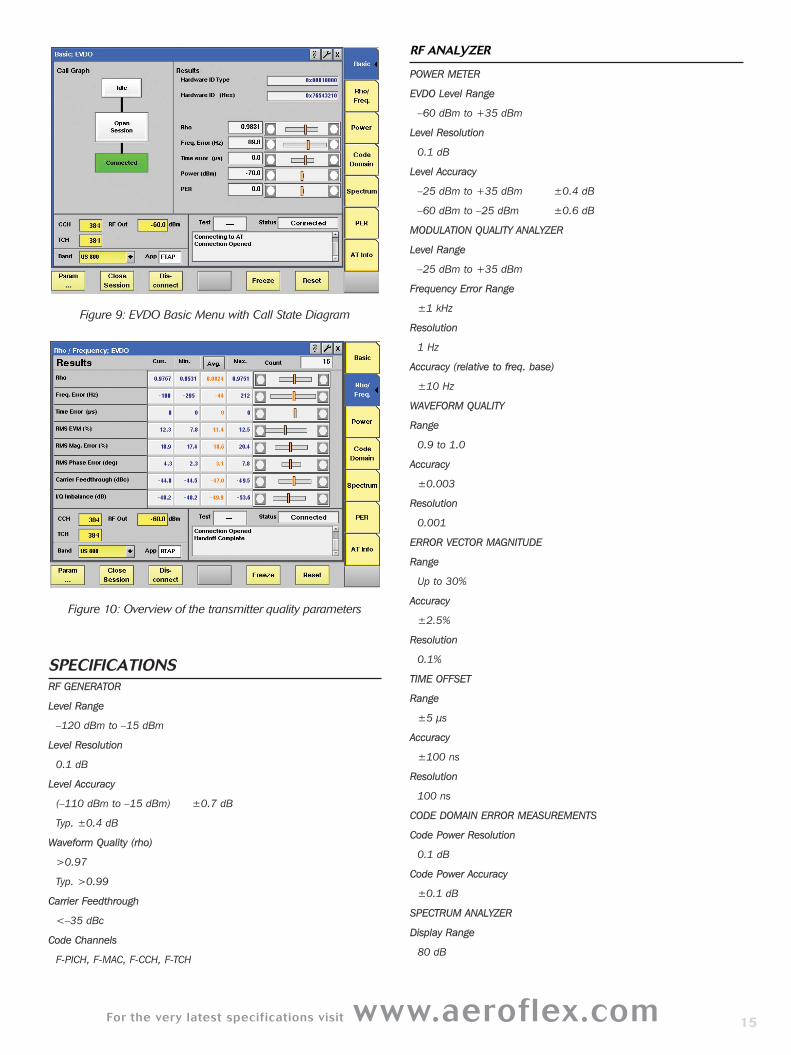
Figure 9: EVDO Basic Menu with Call State Diagram
Figure 10: Overview of the transmitter quality parameters
SPECIFICATIONSRF GENERATOR
Level Range
–120 dBm to –15 dBm
Level Resolution
0.1 dB
Level Accuracy
(–110 dBm to –15 dBm) ±0.7 dB
Typ. ±0.4 dB
Waveform Quality (rho)
>0.97
Typ. >0.99
Carrier Feedthrough
<–35 dBc
Code Channels
F-PICH, F-MAC, F-CCH, F-TCH
RF ANALYZER
POWER METER
EVDO Level Range
–60 dBm to +35 dBm
Level Resolution
0.1 dB
Level Accuracy
–25 dBm to +35 dBm ±0.4 dB
–60 dBm to –25 dBm ±0.6 dB
MODULATION QUALITY ANALYZER
Level Range
–25 dBm to +35 dBm
Frequency Error Range
±1 kHz
Resolution
1 Hz
Accuracy (relative to freq. base)
±10 Hz
WAVEFORM QUALITY
Range
0.9 to 1.0
Accuracy
±0.003
Resolution
0.001
ERROR VECTOR MAGNITUDE
Range
Up to 30%
Accuracy
±2.5%
Resolution
0.1%
TIME OFFSET
Range
±5 µs
Accuracy
±100 ns
Resolution
100 ns
CODE DOMAIN ERROR MEASUREMENTS
Code Power Resolution
0.1 dB
Code Power Accuracy
±0.1 dB
SPECTRUM ANALYZER
Display Range
80 dB
15
Page 16
Resolution Bandwidth
15 kHz, 30 kHz
Span (selectable)
±2.5 MHz
±500 kHz
ACPM
Display Range
80 dB
Frequencies according to IS-98D
Up to 2.5 MHz from centre frequency
Measurements
Spectrum due to modulation
NON-CALL MODE FUNCTIONS
Measurements
Power measurements
Modulation quality measurements
Rho
Frequency error
Rms vector error
Amplitude imbalance
Code domain power
Modulation spectrum
CALL MODE FUNCTIONS
Supported Revisions
Rev. 0, Rev. A
Supported Bands
band 0 - US cellular (ch 1 to 1023)
band 1 - PCS band (ch 1 to 1199)
band 2 - TACS band (ch 1-1000, 1329-2047)
band 3 - JTACS band (ch 1-799, 801-1039, 1041-1199, 1201-1600)
band 4 - Korean PCS (ch 1 to 599)
band 5 - NMT-450 (ch 1-300, 1039-1473, 1792-2016)
band 6 - IMT-2000 (ch 1 to 1199)
band 8 - 1800 MHz (ch 1 to 1499)
band 9 - 900 MHz (ch 1 to 699)
Supported Procedures
AT Session Open
AT & AN Connection
AT & AN Release
AT & AN Session Close
Handover
Terminal information
Hardware ID
Hardware ID type
Session seed
UATI 024
UATI color code
Access Parameters
Open loop adjust (0 to 255 dB)
Preamble length (0 to 7 frames)
Probe initial adjust (-15 to +16 dB)
Probe num step (1 to 15)
Probe power step (0 to 7.5 dB)
Probe sequence max (1 to 15)
Reverse Channel Gain Parameters
Ack channel (-3 to +6 dB)
DRC channel (-9 to +6 dB)
Data offset nominal (-3.5 to 4.0 dB)
Data offset rate (for various rates)
General Parameters
Control channel number
Total RF power
PN offset (0 to 511)
Call Parameters
Physical Layer Subtype
Application
FTAP/FETAP rate
RTAP/RETAP rate
ACK channel bit fixed mode attrib
AT directed packets
Reverse closed loop power control
AT max power
MAC index
Transmitter Measurements
Power measurements
Minimum/maximum RF power
Modulation quality measurements
Rho
Frequency error
Rms vector error
Time offset
Amplitude imbalance
Code domain power
Receiver Measurements
Receiver performance sensitivity
Dynamic range (packet error rate)
16
Page 17
For the very latest specifications visit www.aeroflex.com
OPTIONS FOR GSM, GPRS AND EDGEThe 4400 Mobile Phone Tester Series supports GSM and its
enhancements GPRS and EDGE with different basic options:the GSM
non-call mode and call mode options, the GPRS non-call mode and call
mode options, and the EDGE non-call mode option and call mode
options.
GSM System Options
Worldwide the GSM standard is being applied in four different
frequency bands, all of which are supported by the GSM system
options.
The 4457 GSM Call Mode Option offers a signaling mode in which the
4400 is able to emit a signal similar to that of a GSM base station.
Various signaling parameters can be adjusted to test a GSM mobile
phone under different conditions.
The parameter menu allows signaling parameters to be easily changed.
From the GSM cell parameters, across the definition of SMS message
class, to the call set up procedure details, a lot of parameters are
accessible in the 4400. A range of measurements are supported to test
frequency and phase error, power, spectrum, and various receiver
quality parameters.
The call mode option includes a generic test script to run tests
automatically, without user intervention. This test script consists of a
final test of a GSM mobile phone operating in one or several of the
GSM frequency bands, which are GSM 850 (U.S. cellular band), GSM
900, GSM 1800 and GSM 1900 (U.S. PCS band).
The generator/analyzer mode of the 4458 GSM Non-Call Mode Option
provides basic signal generation capabilities as well as
frequency and phase, burst (power) and spectrum measurements. This
functionality is not limited to GSM channels but available for the whole
frequency range supported by the 4400.
GPRS System Options
GPRS (General Packet Radio Service) adds higher data rate
capabilities to GSM by combining a packet data protocol with bundling
of multiple time slots. The 4462 GPRS Call Mode Option allows
testing of the packet data protocol capability as well as the
multislot transmit and receive quality during a connection. Tests
without the connection setup can be done with the 4454 GPRS
Non-Call Mode Option.
Users who need to test both GSM and GPRS in call mode and
non-call mode, can also use the 4463 GSM/GPRS System Option
combining the capabilities of all the four system options.
EDGE System Options
A further increase in data throughput is achieved with EDGE
(Enhanced Data rates for the Global Evolution), also called Enhanced
GPRS. EGPRS introduces a higher modulation format (8-PSK) which
requires new tests and measurements.
The modulation quality for EDGE-enabled mobile phones is expressed
in Error Vector Magnitude (EVM), origin offset and I/Q imbalance.
Figure 11: GSM Basic Screen
Figure 12: RF Generator/Analyzer Mode
RF GENERATOR
Level Range
–120 dBm to –10 dBm
Level Accuracy (–110 dBm to –10 dBm)
4405 0.7 dB, typ. 0.3 dB
4403 0.9 dB, typ. 0.4 dB
Level Resolution
0.1 dB
Phase Error Rms
2.3°, typ. 1.1°
RF ANALYZER
Peak Power Level Range
–10 dBm to +36 dBm
Dynamic Range
72 dB
Usable Down To
–30 dBm
Phase and Frequency Measurements
17
Page 18
Graphical Display
Phase Error vs. Time
Marker Functions
2 markers, difference indication
Vertical Display Range
±2°, ±5°, ±10°, ±20°, ±50°
Horizontal Display Range
150 bit periods
FREQUENCY ERROR
Display
Current/average/min./max.
Range
±100 kHz
Resolution
1 Hz
Accuracy at 800 MHz to 1000 MHz
Within ±10 kHz error 15 Hz + freq. base
Within ±100 kHz error 20 Hz + freq. base
Accuracy at 1700 MHz to 2000 MHz
Within ±10 kHz error 25 Hz + freq. base
Within ±100 kHz error 30 Hz + freq. base
PHASE ERROR RMS
Display
Current/average/min./max.
Range
0° to 15°
Resolution
0.1°
Accuracy
0.5°, typ. 0.3°
PHASE ERROR PEAK
Display
Current/average/min./max.
Range
0° to 45°
Resolution
0.1°
Accuracy
1° to 15° error 3.2°
15° to 25° error 4.2°
8-PSK (EDGE) Measurements (EDGE System Options)
Level Range
–25 dBm to +36 dBm
FREQUENCY ERROR
Range
±10 kHz
Resolution
1 Hz
Accuracy
Same as GSM specification
RMS EVM
Display
Current/average/min./max.
Range
0 to 50%
Resolution
0.1%
Accuracy
<1.0%
PEAK EVM
Display
Current/average/min./max.
Range
0 to 75%
Resolution
0.1%
Accuracy
<3%
95th PERCENTILE
Display
Current/average/min./max.
Range
0 to 50%
Resolution
0.01%
Accuracy
<1.5%
ORIGIN OFFSET
Display
Current/average/min./max.
Range
0 to 50%
Resolution
0.1%
Accuracy
±0.5 dB
I/Q IMBALANCE
Display
Current/average/min./max.
Range
0 to 50%
Resolution
0.1%
Accuracy
±0.5 dB
BURST MEASUREMENTS
Peak Level Accuracy
4405 0.37 dB1), typ. 0.15 dB
4403 0.8 dB
1 if RX signal >–32 dBm and TX signal >10 dBm
18
Page 19
For the very latest specifications visit www.aeroflex.com
Level Repetition
4405 0.01 dB
4403 0.03 dB
Level Resolution
0.01 dB
Relative Accuracy of 4405
1 dB at –60 dBc
3 dB at –72 dBc
GRAPHICAL DISPLAY
Measurement
Power vs. time
Marker Functions
2 markers, difference indication
Power vs. Time Display Modes
Full burst, edges, flat part
Corner Points
8 measurement points on the burst
Selectable Range
–10 bits to +160 bits
Accuracy
See relative accuracy
Resolution
0.1 dB
TIMING ADVANCE AND TIMING ERROR MEASUREMENT
Setting Range
0 to 63 bit periods
Measurement Resolution
0.1 µs
Measurement Range
± half a time slot (relative to 4400 timing)
MODULATION SPECTRUM
Graphical Display
Power vs. frequency
Display Range
80 dB
Resolution Bandwidth
10 kHz, 30 kHz
Span (selectable)
±1.8 MHz
±500 kHz
±200 kHz
Marker Functions
2 markers, difference indication
Statistical Functions
Current, average
ACPM (ORFS) OPTION
Graphical Display
Bar chart, power vs. frequency
Display Range
80 dB
Frequencies
According to ETSI GSM 11.10 up to 1.8 MHz from centre frequency
Measurements
Spectrum due to modulation
Spectrum due to switching transients
NON-CALL MODE FUNCTIONS
ASYNCHRONOUS RF GENERATOR
Carrier Frequency Selection
By frequency or channel number
Signal Types
Continuous, burst
Modulation
None, GMSK, AM (optional)
Training Sequence
0 to 7 or none
Burst Contents
Fixed bit patterns, PRBS (PN-9, PN-15, PN-23)
ASYNCHRONOUS RF GENERATOR
(Additional specifications for GPRS Non-Call Mode Option)
Signal Type
Continuous, burst, multislot
Selectable channel combinations
Raw GMSK signal
PDTCH (channel comb. 13)
BCH + PDTCH (channel comb. 5 on time slot 0,
Channel comb. 13 on other time slots)
PDTCH Content
RLC/MAC header + data payload
Multislot PDTCH Operation
1 time slot generated and duplicated
PDTCH Data Payload
PN-9, PN-15, PN-23, 1010...
Multislot Power Level
Individually selectable for each time slot
ASYNCHRONOUS RF ANALYZER
Carrier Frequency Selection
By frequency or channel number
Supported Signal Type
GMSK-modulated burst signal
GMSK-modulated continuous signal
Time Synchronisation of MS with 4400
Not required
RF Power Conditions
>–20 dBm
Supported Transmitter Measurements
Peak power
19
Page 20
Burst power (full range)
Corner points
Frequency/phase error measurements
Spectrum measurements
ASYNCHRONOUS RF ANALYZER
(Additional specifications for GPRS Non-Call Mode Option)
In multislot mode, the specified measurement accuracy applies to the
time slot with the highest power level.
Maximum Number of Tme Slots
Up to 4 adjacent time slots
Supported Transmitter Measurements
Same as for GSM, displayed results for selectable time slot, results via
SCPI for one selectable slot or for all time slots
ASYNCHRONOUS RF ANALYZER
(Additional specifications for EDGE Non-Call Mode Option)
In multislot mode, the specified measurement accuracy applies to the
time slot with the highest power level.
Maximum Number of Time Slots
Up to 4 adjacent time slots
Supported Transmitter Measurements
Frequency error, RMS EVM, peak EVM 95th percentile, origin offset, I/Q
imbalance displayed results for selectable time slot, results via SCPI for 1
selectable of for all time slots
CALL MODE FUNCTIONS
Supported Bands
GSM 850 (channels 128 to 251)
P-GSM (channels 1 to 124)
E-GSM (channels 975 to 1023, 0 to 124)
R-GSM (channels 955 to 1023, 0 to 124)
GSM 1800 (channels 512 to 885)
GSM 1900 (channels 512 to 810)
GSM CALL PROCESSING
Supported Procedures
Location update
Mobile-originated call
Mobile-terminated call
Intracell handover
Cross-band intracell handover
Call clearing by MS
Call clearing by 4400
Open loop, closed loop procedures
Early or late assignment
SMS to mobile (idle mode)
SMS to mobile (on TCH/FS)
SMS from mobile (idle mode)
Special Functions
Call state diagram
Paging test
Reduced signalling
TCH Slot
Selectable, range 2 to 6
GPRS CALL PROCESSING
Time slot selection automatic, according to multislot class
Supported Procedures
GPRS attach/detach
Routing area update
Downlink TBF establishment
Uplink TBF establishment
(Using ETSI-defined GPRS test mode command) reduced signalling
Uplink Data Mode According to GSM 04.14 test mode a)
(Without data loopback in the mobile)
Uplink Power Control Method
Closed loop
EDGE CALL PROCESSING
Time Slot Selection
Automatic, according to multislot class
Supported Procedures
EDGE attach/detach
Uplink TBF establishment
ETSI test mode A only
GPRS Transmitter Measurements
The measurement accuracy specified for the base unit applies to the
time slot with the highest power level.
Supported Number of Time Slots
Transmitter measurements: 1 through 4
RF Power Conditions
At least 1 time slot at >–20 dBm
Max. adjacent slot power difference: 30 dB
Power Measurements
Peak power for selectable time slot
Min., max., average, current values
8 corner points for selectable time slot
Power vs. time for selectable no. of time slots
Frequency/phase Error Measurements
Measurements for selectable time slot
Min., max., average, current values
Spectrum Measurements
Modulation spectrum (for selectable slot)
Spectrum due to modulation (selectable slot)
Spectrum due to switching transients
EDGE TRANSMITTER MEASUREMENTS
The measurement accuracy specified for the base unit applies to the
time slot with the highest power level.
Supported Number of Time Slots
Transmitter measurements: 1 through 4
RF Power Conditions
At least 1 time slot at >–20 dBm
Max. adjacent slot power difference: 30 dB
Power Measurements
Peak power for selectable time slot
Min., max., average, current valueS
8 corner points for selectable time slot
Power vs. time for selectable no. of time slots20
Page 21
For the very latest specifications visit www.aeroflex.com
MODULATION QUALITY MEASUREMENTS
Frequency error, RMS EVM, peak EVM
95th percentile, origin offset, I/Q imbalance
Min., max., average, current values
Spectrum Measurements
Modulation spectrum (for selectable slot)
Spectrum due to modulation (selectable slot)
Spectrum due to switching transients
GSM RECEIVER MEASUREMENTS
Supported Measurements
Bit Error Rate (BER)
Residual Bit Error Rate (RBER)
Fast Bit Error Rate (FBER, C loop)
Frame Erasure Rate (FER)
Selectable Patterns
Fixed bit patterns, PRBS (PN-9, PN-15, PN-23)
Displayed Results
Current, average, min., max.
Number of Samples
BER 1000 to 106 bits
RBER 10 to 106 bits
Fast BER 100 to 106 bits
Supported Channels
TCH/FS, TCH/EFS
GPRS RECEIVER MEASUREMENTS
Displayed Results
Minimum, maximum, average BLER/BER
Coding Scheme
CS-1
Data
PRBS (PN-9, PN-15, PN-23)
BLER-BCS Measurement
Number of time slots Up to 4
Concurrent TX tests No
Number of blocks 10 to 999
BLER-USF Measurement
Number of time slots Up to 4
Concurrent TX tests Yes, up to 4 time slots
Number of blocks 10 to 999
EDGE RECEIVER MEASUREMENTS
Displayed Results
Minimum, maximum, average BLER
Coding Scheme
CS-1
BLER-USF MEASUREMENT
Number of time slots
Up to 4
Concurrent TX tests
Yes, up to 4 time slots
Number of Blocks
10 to 999
TCH LOOPBACK IN THE 4400
Speech Loopback
Full rate, enhanced full rate
Data Loopback
9.6 kbit/s, transparent data
14.4 kbit/s, transparent data
ORDERING DETAILS
Aeroflex 4403 Mobile Phone Tester AG 101 105
Aeroflex 4405 Mobile Phone Tester AG 101 104
System Options
4445 GSM/GPRS Call Mode Option AG 897 297
4446 GSM/GPRS Non-Call Mode Option AG 897 298
4447 CDMA2000 1xRTT Non-Call Mode AG 897 299
Option
4448 CDMA2000 1xRTT Call Mode Option AG 897 300
4449 EDGE Non-Call Mode Option AG 897 301
4450 TD-SCDMA Non-Call Mode Option AG 897 255
4451 TD-SCDMA Call Mode Option AG 897 256
4452 1xEV-DO Non-Call Mode Option AG 897 287
4453 1xEV-DO Call Mode Option AG 897 288
4454 GPRS Non-Call Mode Option AG 897 302
4455 HSDPA Call Mode Option AG 897 304
4456 HSDPA Non-Call Mode Option AG 897 303
4457 GSM Call Mode Option AG 897 305
4458 GSM Non-Call Mode Option AG 897 306
4460 GSM/GPRS/EDGE Hardware Option AG 248 710
4462 GPRS Call Mode Option AG 897 307
4463 GSM/GPRS System Option AG 248 712
4464 CDMA2000 1xRTT Hardware Option AG 248 711
4466 WCDMA/UMTS Non-Call Mode Option AG 897 248
4467 WCDMA/UMTS Call Mode Option AG 897 249
4468 EDGE Call Mode Option AG 897 308
4479 Baseband Processing Hardware AG 248 690
7312 Lector Enhanced AG 897 310
7315 Scriptor AG 897 311
General Options
4473 MS Power Supply Option AG 248 355
4474 MS Current Measurement Option AG 248 356
21
Page 22
4477 OCXO AG 214 028
GSM Options
1103 USIM and GSM Test SIM card AG 860 164
1104 Test Micro USIM Card (3FF) AG 860 147
4470 Audio Option AG 248 360
4471 Basic Codec Option AG 248 364
4472 Codec Extension Option AG 897 156
4475 ACPM (ORFS) Option AG 897 163
4481 AM Signal Generator Option AG 897 165
CDMA Options
4470 Audio Option for CDMA-only units AG 248 653
WCDMA Option
1103 USIM and GSM Test SIM card AG 860 164
1104 Test Micro USIM Card (3FF) AG 860 147
Accessories
Carrying case AG 300 808
Rack mount set AG 378 260
4916 Antenna Coupler AG 248 641
4921 RF Shield AG 248 346
RF Shield and Antenna Coupler package AG 248 348
22
Page 23
For the very latest specifications visit www.aeroflex.com 23
Page 24
Part No. 46891/392, Issue 1, 07/10
CHINA BeijingTel: [+86] (10) 6539 1166Fax: [+86] (10) 6539 1778
CHINA ShanghaiTel: [+86] (21) 5109 5128Fax: [+86] (21) 5150 6112
CHINA ShenzhenTel: [+86] (755) 3301 9358 Tel: [+86] (755) 3301 9356
FINLANDTel: [+358] (9) 2709 5541Fax: [+358] (9) 804 2441
FRANCETel: [+33] 1 60 79 96 00 Fax: [+33] 1 60 77 69 22
GERMANYTel: [+49] 8131 2926-0 Fax: [+49] 8131 2926-130
HONG KONGTel: [+852] 2832 7988Fax: [+852] 2834 5364
INDIATel: [+91] 80 [4] 115 4501Fax: [+91] 80 [4] 115 4502
KOREA Tel: [+82] (2) 3424 2719Fax: [+82] (2) 3424 8620
SCANDINAVIATel: [+45] 9614 0045 Fax: [+45] 9614 0047
UK StevenageTel: [+44] (0) 1438 742200Fax: [+44] (0) 1438 727601Freephone: 0800 282388
USATel: [+1] (316) 522 4981 Fax: [+1] (316) 522 1360Toll Free: 800 835 2352
w w w . a e r o f l e x . c o m
i n f o - t e s t @ a e r o f l e x . c o m
As we are always seeking to improve our products,the information in this document gives only a generalindication of the product capacity, performance andsuitability, none of which shall form part of any con-tract. We reserve the right to make design changeswithout notice. All trademarks are acknowledged. Parent company Aeroflex, Inc. ©Aeroflex 2010.