25
SIGTRAN - Protocol Analysis & System Integration INACON GmbH Kriegsstrasse 154 76133 Karlsruhe Germany www.inacon.com e-mail: [email protected]

SIGTRAN -
Protocol Analysis &
System Integration
INACON GmbH Kriegsstrasse 154 76133 Karlsruhe
Germany www.inacon.com
e-mail: [email protected]

Legend:
All INACON publications use the same color codes to distinguish mandatory from optional or conditional parts in frame formats or optional from mandatory data blocks or signaling messages in scenarios. The different color codes are explained underneath:
• Color Codes in Frame Formats:
• Color Codes in Scenarios:
Signaling Message (mandatory)
Signaling Message (optional) Data (mandatory)
Data (optional)

- 2 -
SIGTRAN – Protocol Analysis & System Integration
1
© INACON GmbH 1999 - 2007. All rights reserved. Reproduction and/or unauthorized use of this material is prohibited and will be prosecuted to the full extent of German and international laws. Version Number 1.501
1.1 The Legacy CCS7-Protocol Stack
The objective of this section is to illustrate the most important protocols within the CCS7-protocol stack, their relation to the OSI-reference model and whether or not they are or may be replaced through SIGTRAN-protocols.
Key point of this section is that SIGTRAN can replace CCS7-based signaling transport up to different layers of the CCS7-protocol stack.
• It is basically an implementation option which layers of the CCS7-protocol stack are replaced by SIGTRAN.
• It is the major function of the different adaptation protocols like M2UA or SUA to mimic the respective CCS7-transport protocols towards their application protocols.
• We will illustrate at a later time in chapter 4 that specific adaptation protocols like IUA or V5UA do not even replace layers of the CCS7-protocol stack but on the user-network interface (e.g. D-channel on the U-interface).
The adaptation layer protocols for TCAP (TUA) and ISUP (ISUA) are currently still in the standardization phase. Only internet drafts exist: draft-bidulock-sigtran-tua-XX.txt, draft-bidulock-sigtran-isua-XX.txt

- 14 -
SIGTRAN – Protocol Analysis & System Integration
1
© INACON GmbH 1999 - 2007. All rights reserved. Reproduction and/or unauthorized use of this material is prohibited and will be prosecuted to the full extent of German and international laws. Version Number 1.501
1.2 Introducing SIGTRAN
The objective of this section is to illustrate the principles and the meaning of SIGTRAN as IP-based transport protocol suite for CCS7-protocols.
The key point of this section is that SIGTRAN provides a transport layer to allow CCS7-application protocols to be transported over IP-networks.
Image Description • The figure illustrates the registration process of a roaming mobile user. • The necessary CCS7-application layer messaging between the VLR in the visited
network and the HLR in the home network is not transported over MTP-based transport but using the internet or the GRX and SIGTRAN.
Mobile operators prefer the use of the existing GRX-network because of security and QoS-issues.

- 16 -
SIGTRAN – Protocol Analysis & System Integration
1
© INACON GmbH 1999 - 2007. All rights reserved. Reproduction and/or unauthorized use of this material is prohibited and will be prosecuted to the full extent of German and international laws. Version Number 1.501
1.2.1 The CCS7-Protocol Stack in Case of SIGTRAN
The objective of this section is to illustrate the CCS7-protocols if SIGTRAN is used underneath them up to different levels.
The key points of this section are: 1. Different variations of SIGTRAN exist and allow the replacement of more or less many vertical protocols of the legacy CCS7-protocol stack. 2. There exists apparently quite a number of XUA-layers. 2. The SCTP-layer is inherent whenever SIGTRAN is used.
Additional Information The remark at the top of the figure “repeats here” shall indicate that the indicate SCCP-users (TCAP, BSSAP, RANAP, …) may also reside on the top of the rightmost protocol stack.

- 34 -
SIGTRAN – Protocol Analysis & System Integration
1
© INACON GmbH 1999 - 2007. All rights reserved. Reproduction and/or unauthorized use of this material is prohibited and will be prosecuted to the full extent of German and international laws. Version Number 1.501
1.4 Overview of the Adaptation Layers
The objective of this section is to introduce the user adaptation layer protocols SUA, M3UA and M2UA.
Key point of this section is that the adaptation layers are necessary in the SIGTRAN-stack to emulating the respective CCS7-protocol services that they replace.
1.4.1 SUA The SUA has been described in RFC 3868. It fully replaces the connection-less and connection-oriented services that the SCCP offers to its application layers. SUA may for instance be used within the core network or within the RAN, e.g. on the Iu-cs-, Iu-ps- or Iur-interfaces.
1.4.2 M3UA The M3UA has been described in RFC 4666. It fully replaces the services that the MTP-3 offers to its application layers.
- 35 -
Introduction
1
© INACON GmbH 1999 - 2007. All rights reserved. Reproduction and/or unauthorized use of this material is prohibited and will be prosecuted to the full extent of German and international laws. Version Number 1.501
1.4.3 M2UA The M2UA has been described in RFC 3331. M2UA replaces the CCS7-protocol layers MTP-1 and MTP-2 and allows the piggybacking of MSU’s through an IP-based protocol stack within M2UA-envelopes.
Towards their application layer, e.g. MTP-2, MTP-3, SCCP or TCAP, the user adaptation layers mimic and emulate the message primitives that these application layers expect.
Room for your Notes
----------------------------------------------------------------------------------------------------------------------------------------
----------------------------------------------------------------------------------------------------------------------------------------
----------------------------------------------------------------------------------------------------------------------------------------
----------------------------------------------------------------------------------------------------------------------------------------
• Abbreviations of this Section:
CCS7 Common Channel Signaling System No. 7 (ITU-T Q-series of specifications, in particular Q.700 - Q.703)
RAN Radio Access Network
IP Internet Protocol (RFC 791) RFC Request for Comments (Internet Standards)
ISUP ISDN User Part (ITU-T Q.761 - Q.765)
SAP Service Access Point
M2UA MTP-2 User Adaptation Layer (RFC 3331)
SCCP Signaling Connection Control Part (ITU-T Q.711 - Q.714)
M3UA MTP-3 User Adaptation Layer (RFC 4666)
SIGTRAN Signaling Transport (RFC 2719)
MSU Message Signal Unit SUA SCCP User Adaptation Layer (RFC 3868)
MTP Message Transfer Part (ITU-T Q.701 - Q.709)
TCAP Transaction Capabilities Application Part (Q.771 - Q.773)

- 54 -
SIGTRAN – Protocol Analysis & System Integration
1
© INACON GmbH 1999 - 2007. All rights reserved. Reproduction and/or unauthorized use of this material is prohibited and will be prosecuted to the full extent of German and international laws. Version Number 1.501
1.7.5 Use Case 5: Access Network / Core Network Interconnection
The objective of this section is to illustrate how access networks can be coupled with their core networks.
The key points of this section are: 1. When it comes to plain CCS7-traffic volume, then BSSAP- and RANAP/RNSAP-based traffic accounts for app. 67 % of the overall CCS7-traffic. 2. As long as there are GSM- and UMTS-networks with BSSAP- and RANAP-protocols in use, SIGTRAN will prevail. 3. The similarity of the protocol stacks in the middle and on the right side, if the one on the right side deploys SCTP and an AN-specific application protocol.

- 55 -
Introduction
1
© INACON GmbH 1999 - 2007. All rights reserved. Reproduction and/or unauthorized use of this material is prohibited and will be prosecuted to the full extent of German and international laws. Version Number 1.501
Image Description • The image illustrates three protocol stacks: The two ones on the left side illustrate
legacy protocol stacks with BSSAP and RANAP as protocols for interconnecting BSC’s and RNC’s to the 2G/3G-core network.
• In case of SIGTRAN (the green protocols) the use of SUA is not mandatory. For instance, an implementation could also use M3UA and SCCP underneath BSSAP or RANAP.
• The protocol stack on the right side gives an idea of how the same interconnection is achieved in an IP-originated environment with new access networks like WIMAX. In that respect, the TTG is really part of the so called PDG which incorporates the 3G-specific GGSN plus the TTG.
• Abbreviations of this Section:
ATM Asynchronous Transfer Mode (ITU-T I.361)
RANAP Radio Access Network Application Part (3GTS 25.413)
BSC Base Station Controller RNC Radio Network Controller
BSSAP Base Station Subsystem Application Part
RNSAP Radio Network Subsystem Application Part (3GTS 25.423)
CCS7 Common Channel Signaling System No. 7 (ITU-T Q-series of specifications, in particular Q.700 - Q.703)
SCCP Signaling Connection Control Part (ITU-T Q.711 - Q.714)
GERAN GSM EDGE Radio Access Network SCTP Stream Control Transmission Protocol (RFC 2960)
GGSN Gateway GPRS Support Node SIGTRAN Signaling Transport (RFC 2719)
GSM Global System for Mobile Communication
SUA SCCP User Adaptation Layer (RFC 3868)
IKE Internet Key Exchange (RFC 2409)
TCP Transmission Control Protocol
IP Internet Protocol (RFC 791) TTG Tunnel Termination Gateway
IPsec Internet Protocol / secure (RFC 4301)
UDP User Datagram Protocol (RFC 768)
M3UA MTP-3 User Adaptation Layer (RFC 4666)
UMTS Universal Mobile Telecommunication System
MOBIKE IKEv2 Mobility and Multihoming Protocol (RFC 4555)
UTRAN UMTS (Universal Mobile Telecommunication System) Terrestrial Radio Access Network
MTP Message Transfer Part (ITU-T Q.701 - Q.709)
WIMAX Worldwide Interoperability for Microwave Access (IEEE 802.16)
PDG Packet Data Gateway WLAN Wireless Local Area Network (IEEE 802.11)

- 68 -
SIGTRAN – Protocol Analysis & System Integration
2
© INACON GmbH 1999 - 2007. All rights reserved. Reproduction and/or unauthorized use of this material is prohibited and will be prosecuted to the full extent of German and international laws. Version Number 1.501
2.2.2 End-to-End Routing through the SCCP
The objective of this section is to expand the aforementioned SPC-based routing concept through end-to-end addressing means.
Key points of this section are: 1. Different networks cannot synchronize their configuration and therefore universal identifiers like the IMSI or E.164-numbers serve as input to determine a possibly intermediate target SPC. 2. SCCP-enabled STP’s like the one at bullets 2 and 3 will build new MSU’s with their SPC as OPC.
Image Description • The image illustrates the way of an SCCP-message which is embedded in an
MSU from an MSC through two STP’s to an HLR. • The respective SCCP-subsystem (MAP) is only present in the two peers. The originating MSC is unable to resolve the final DPC (of the HLR) and therefore this operation only provided the DPC of the STP at bullet 4. When the MSU reaches its “final” recipient (the STP at bullet 4) the MTP provides the SCCP-message upwards to the SCCP-layer.

- 69 -
Reviewing Important Assets of the CCS7 Protocol Suite
2
© INACON GmbH 1999 - 2007. All rights reserved. Reproduction and/or unauthorized use of this material is prohibited and will be prosecuted to the full extent of German and international laws. Version Number 1.501
The STP’s SCCP-layer is in charge to evaluate the called party address information, usually provided as global title and represented as E.164-number or IMSI. Through an internal (or external) routing table, the local SCCP is in charge to determine from this global title the final DPC or the next far hop DPC. However, in our case the final recipient’s SPC can be determined.
This process is termed GTT or Global Title Translation.
Please put in the SPC’s and the SLS in the related fields in the drawing for the two MSU’s. Will the SLS differ between the two MSU’s?
Room for your Notes
----------------------------------------------------------------------------------------------------------------------------------------
----------------------------------------------------------------------------------------------------------------------------------------
----------------------------------------------------------------------------------------------------------------------------------------
----------------------------------------------------------------------------------------------------------------------------------------
• Abbreviations of this Section:
CCS7 Common Channel Signaling System No. 7 (ITU-T Q-series of specifications, in particular Q.700 - Q.703)
MSU Message Signal Unit
DPC Destination Point Code MTP Message Transfer Part (ITU-T Q.701 - Q.709)
GTT Global Title Translation (ITU-T Q.714 (2.4))
OPC Originating Point Code
HLR Home Location Register SCCP Signaling Connection Control Part (ITU-T Q.711 - Q.714)
IMSI International Mobile Subscriber Identity
SPC Signaling Point Code
MAP Mobile Application Part STP Signaling Transfer Point
MSC Mobile Services Switching Center

- 86 -
SIGTRAN – Protocol Analysis & System Integration
2
© INACON GmbH 1999 - 2007. All rights reserved. Reproduction and/or unauthorized use of this material is prohibited and will be prosecuted to the full extent of German and international laws. Version Number 1.501
2.4.3 SCCP-Connection Operation and Identification
The objective of this section is to illustrate SCCP-connection establishment, operation and release using protocol class 1 (DT1-messages).
Keys point of this section is to recognize that SCCP-connections and the related messages can unambiguously be identified through their local reference numbers SLR and/or DLR.
Image Description • The image illustrates how the RNC establishes an SCCP-connection with the
SGSN. • The SCCP-CR-message is uniquely identified through the 24 bit long SLR. This
SLR serves as DLR in all SCCP-messages in the opposite direction that belong to the new connection.
• The SGSN provides its own SLR within the SCCP-CC-message that confirms the connection establishment.

- 87 -
Reviewing Important Assets of the CCS7 Protocol Suite
2
© INACON GmbH 1999 - 2007. All rights reserved. Reproduction and/or unauthorized use of this material is prohibited and will be prosecuted to the full extent of German and international laws. Version Number 1.501
• Consecutive data transfer in both directions is performed using DT1-messages
(or DT2-message if acknowledgements are required). Note that DT1-messages only carry the DLR.
• Finally, SCCP-connection release is performed using the respective messages.
SCCP-Connections and SLS-based Loadsharing: • SCCP-connections are evenly distributed over the 16 SLS-values. However, once
a given SLS is used, it prevails throughout the lifetime of the SCCP-connection.
That is: All SCCP-messages in one direction belonging to the same SCCP-connection are mapped to the same CCS7-link.
Room for your Notes
----------------------------------------------------------------------------------------------------------------------------------------
----------------------------------------------------------------------------------------------------------------------------------------
----------------------------------------------------------------------------------------------------------------------------------------
----------------------------------------------------------------------------------------------------------------------------------------
----------------------------------------------------------------------------------------------------------------------------------------
• Abbreviations of this Section:
CCS7 Common Channel Signaling System No. 7 (ITU-T Q-series of specifications, in particular Q.700 - Q.703)
RNC Radio Network Controller
DLR Destination Local Reference (SCCP term)
SCCP Signaling Connection Control Part (ITU-T Q.711 - Q.714)
DT1 Data Form 1 (SCCP message type) SGSN Serving GPRS Support Node
PDU Protocol Data Unit or Packet Data Unit
SLR Source Local Reference
RANAP Radio Access Network Application Part (3GTS 25.413)
SLS Signaling Link Selection

- 110 -
SIGTRAN – Protocol Analysis & System Integration
3
© INACON GmbH 1999 - 2007. All rights reserved. Reproduction and/or unauthorized use of this material is prohibited and will be prosecuted to the full extent of German and international laws. Version Number 1.501
3.4 Details of RTO- and RTT-Measurements
The objective of this section is to illustrate how retransmission timer measurements are conducted within SCTP and how the related timers RTO, SRTT and RTTVAR are determined from these measurements.
Key points of this section are: 1. The related procedure and formula are the same as used in TCP. 2. SCTP differs from TCP because of the multihoming feature: SRTT-, RTTVAR- and RTO-determination must be done per path. 3. It is not illustrated in the image but the related measurements and calculations are also performed per path in the opposite direction.
Image Description The image illustrates two SCTP-peers of which the left one performs RTT-measurements through transmitting appropriate chunks towards its peer. The peer on the right side is obligated to respond with the correct response chunk which allows the left side to perform an RTT-measurement. As illustrated, SRTT and RTO are functions f(x) of the RTT and its variability RTTVAR.

- 111 -
Details of SCTP
3
© INACON GmbH 1999 - 2007. All rights reserved. Reproduction and/or unauthorized use of this material is prohibited and will be prosecuted to the full extent of German and international laws. Version Number 1.501
Formula to calculate the Retransmission Timeout:
RTO(new) = SRTT(new) + 4 x RTTVAR
Formula to calculate the Smoothed Round-Trip-Time:
SRTT(new) = (1 – α) x SRTT(old) + α x RTT
With α = 0.125 (called RTO.Alpha in SCTP)
When you take the suggested Alpha-value of 0.125 into account: What does this formula mean with respect to weighing all previous measurement results of RTT vs. the latest measurement result?
Formula to calculate the Round-Trip-Time Variability:
RTTVAR(new) = (1 – ß) x RTTVAR(old) + …
… ß x ⎪SRTT - RTT⎪ With ß = 0. 25 (called RTO.Beta in SCTP) [RFC 2960 (6.3.1, 14)]
Room for your Notes
----------------------------------------------------------------------------------------------------------------------------------------
----------------------------------------------------------------------------------------------------------------------------------------
• Abbreviations of this Section:
RFC Request for Comments (Internet Standards)
SACK Selective Acknowledgement
RTO Retransmission Time Out SCTP Stream Control Transmission Protocol (RFC 2960)
RTT Round Trip Time SRTT Smoothed RoundTrip Time
RTTVAR Round Trip Time Variation TCP Transmission Control Protocol

- 126 -
SIGTRAN – Protocol Analysis & System Integration
3
© INACON GmbH 1999 - 2007. All rights reserved. Reproduction and/or unauthorized use of this material is prohibited and will be prosecuted to the full extent of German and international laws. Version Number 1.501
3.5.3.2 Bad Case (Chunk needs to be retransmitted)
The objective of this section is to illustrate how to indicate unsuccessful reception of DATA-chunks towards the original transmitter.
Key point of this section is to recognize the joint operation of the different parameters in a SACK-chunk and to link it to the receiver window on the right side.
Image Description • The image illustrates two SCTP-peers of which the one on the left side is
transmitting three consecutive SCTP-packets with six DATA-chunks to its peer. • Unfortunately, the second SCTP-packet gets lost. • Upon reception of the third SCTP-packet the receiver is able to determine the
loss of the DATA-chunk with TSN = 3. • The immediately transmitted SACK indicates the missing TSN.

- 127 -
Details of SCTP
3
© INACON GmbH 1999 - 2007. All rights reserved. Reproduction and/or unauthorized use of this material is prohibited and will be prosecuted to the full extent of German and international laws. Version Number 1.501
3.5.3.2.1 Error Description The error in this case is a packet loss and no RTO-expiry or CRC-error. However, even at the time of reception of the third SCTP-packet with TSN = 4, 5 and 6 the receiver cannot tell whether the DATA-chunk with TSN-3 is late or lost.
3.5.3.2.2 Immediate Acknowledgement An immediate acknowledgement is triggered for two reasons: 1. The missing DATA-chunk shall immediately be reported. 2. Two SCTP-packets with DATA-chunks have been received. A delayed Acknowledgement is not appropriate.
3.5.3.2.3 Fast Retransmit Algorithm in SCTP Maybe surprisingly but explainable because SACK’s may be received out of sequence, it requires four SACK-chunks before a missing DATA-chunk (in this case with TSN = 3) is “fast” retransmitted.
Of course, retransmission will also occur when RTO expires for that DATA-chunk. It depends on the situation which trigger occurs earlier. However, RTO-expiry has more serious consequences for the performance (cwnd = 1 x PMTU).
However, it is not permitted to just transmit four consecutive SACK-chunks to trigger the immediate retransmission of the DATA-chunk. Each SACK-chunk can only be triggered by the reception of a DATA-chunk carrying SCTP-packet. [RFC 2960 (6.2.1, 7.2.4)]
3.5.3.2.4 Interpretation of the Gap Block Information Element Each SACK-chunk can indicate multiple gaps in the receiver window. In our case we have a single gap (No of Gap Blocks = 1) which starts with TSN = 4 (Gap Block 1 Start = 4) and continues towards TSN = 6 (Gap Block 1 End = 6). [RFC 2960 (3.3.4, 6.2.1)]
Take as example that the lost DATA-chunk with TSN = 3 would be part of the same stream as the DATA-chunk with TSN = 6. However, DATA-chunks with TSN = 4 and 5 shall belong to different streams. In this case, DATA-chunk with TSN = 6 needs to wait for the proper reception of DATA-chunk with TSN = 3 but TSN = 4 and 5 can already be delivered to the upper layer. The wait-requirement for TSN = 6 only applies if ordered delivery [RFC 2960 (p.80)] as default operation mode is used for that DATA-chunk.
• Abbreviations of this Section:
ACK Acknowledgement (3GTS 25.214, 25.308, 25.309)
SACK Selective Acknowledgement
CRC Cyclic Redundancy Check SCTP Stream Control Transmission Protocol (RFC 2960)
PMTU Path MTU TSN Transmission Sequence Number
RTO Retransmission Time Out cwnd Congestion window

- 158 -
SIGTRAN – Protocol Analysis & System Integration
3
© INACON GmbH 1999 - 2007. All rights reserved. Reproduction and/or unauthorized use of this material is prohibited and will be prosecuted to the full extent of German and international laws. Version Number 1.501
3.10.2 Counter
The objective of this section is to present the SCTP-parameters Association.Max.Retrans, Path.Max.Retrans and Max.Init.Retransmits.
[RFC 2960 (14)]
If Max.Init.Retransmits = 8 then after how many seconds will the SCTP-layer report a negative association setup result to the upper layer?
- 159 -
Details of SCTP
3
© INACON GmbH 1999 - 2007. All rights reserved. Reproduction and/or unauthorized use of this material is prohibited and will be prosecuted to the full extent of German and international laws. Version Number 1.501
3.10.2.1 Association.Max.Retrans Recommended values depend on Multihoming Situation. Association is really closed while path (see next point) is only set to inactive. In case of M2PA: Single-homed clients with multiple associations between them: Association.Max.Retrans = 3 (with RTO.Max = 250 ms) or 4 (with RTO.Max = 150 ms) is necessary to meet a changeover time of 800 ms (as required by Q.708).
3.10.2.2 Path.Max.Retrans Path is only set to inactive but is not set to out of service. An alternate path takes over in case of multihoming after Path.Max.Retrans negative retransmissions. Retransmissions in case of Multihoming shall anyways be sent on an alternate path [RFC 2960 (p.79)]. Still, new DATA-chunks continue to be sent on the current primary path [RFC 2960 (p.78)]. In case of M2PA: Multi-homed clients with multiple paths between them: Path.Max.Retrans = 3 (with RTO.Max = 250 ms) or 4 (with RTO.Max = 200 ms) or 5 (with RTO.Max = 150 ms) is necessary to meet a changeover time of 800 ms (as required by Q.708).
3.10.2.3 Max.Init.Retransmits Nothing to add to what is stated in the image.
Room for your Notes
----------------------------------------------------------------------------------------------------------------------------------------
----------------------------------------------------------------------------------------------------------------------------------------
----------------------------------------------------------------------------------------------------------------------------------------
----------------------------------------------------------------------------------------------------------------------------------------
----------------------------------------------------------------------------------------------------------------------------------------
----------------------------------------------------------------------------------------------------------------------------------------
• Abbreviations of this Section:
RFC Request for Comments (Internet Standards)
RTO Retransmission Time Out
SCTP Stream Control Transmission Protocol (RFC 2960)

- 178 -
SIGTRAN – Protocol Analysis & System Integration
4
© INACON GmbH 1999 - 2007. All rights reserved. Reproduction and/or unauthorized use of this material is prohibited and will be prosecuted to the full extent of German and international laws. Version Number 1.501
4.1.5.1 SCCP-Based Routing in case of M3UA
The objective of this section is to illustrate how SIGTRAN-enabled network nodes with M3UA can receive CCS7-messages through an SGW without requiring SPC’s.
The key points of this section are: 1. The resulting routing key may be determined differently, e.g. simpler through the DPC. 2. It may also require additional steps 4, 5, … if for instance multiple HLR’s exist as potential message destinations.
Image Description • The image illustrates the 3-step routing decision within as M3UA SGW for an
MSU that is bound for an HLR within an IP-network. • The three steps are based on the DPC of the MSU, the user part being SCCP
and the subsystem number being HLR. The result is the M3UA-specific routing key.
• If more than one HLR would exist a global title translation would be necessary. [RFC 4666 (1.4.2)]

- 179 -
Details of the User Adaptation Layers
4
© INACON GmbH 1999 - 2007. All rights reserved. Reproduction and/or unauthorized use of this material is prohibited and will be prosecuted to the full extent of German and international laws. Version Number 1.501
Room for your Notes
----------------------------------------------------------------------------------------------------------------------------------------
----------------------------------------------------------------------------------------------------------------------------------------
----------------------------------------------------------------------------------------------------------------------------------------
----------------------------------------------------------------------------------------------------------------------------------------
----------------------------------------------------------------------------------------------------------------------------------------
----------------------------------------------------------------------------------------------------------------------------------------
----------------------------------------------------------------------------------------------------------------------------------------
• Abbreviations of this Section:
CCS7 Common Channel Signaling System No. 7 (ITU-T Q-series of specifications, in particular Q.700 - Q.703)
SCCP Signaling Connection Control Part (ITU-T Q.711 - Q.714)
DPC Destination Point Code SGSN Serving GPRS Support Node
HLR Home Location Register SGW Signaling Gateway
IP Internet Protocol (RFC 791) SI Service Indicator
ISUP ISDN User Part (ITU-T Q.761 - Q.765)
SIGTRAN Signaling Transport (RFC 2719)
M3UA MTP-3 User Adaptation Layer (RFC 4666)
SIO Service Information Octet
MSC Mobile Services Switching Center SLS Signaling Link Selection
MSC-S MSC-Server SPC Signaling Point Code
OPC Originating Point Code SSF Service Switching Function (CAMEL)
RFC Request for Comments (Internet Standards)
VLR Visitor Location Register

- 208 -
SIGTRAN – Protocol Analysis & System Integration
4
© INACON GmbH 1999 - 2007. All rights reserved. Reproduction and/or unauthorized use of this material is prohibited and will be prosecuted to the full extent of German and international laws. Version Number 1.501
4.3.3 M3UA
The objective of this section is to illustrate how M3UA applies SCTP-associations and streams.
Key points of this section are: 1. To recognize the similarity between M2UA and M3UA with respect to handling associations and streams. 2. To recognize the flexibility in stream management in SIGTRAN considering the different mapping rules on either side.
Image Description • The image illustrates two CCS7-peers that are interconnected to each other
through two SGW’s that deploy M3UA. • Opposed to the previous two examples, the CCS7-linkset on the left side consists
of four links while the other one consists of only two links. Each CCS7-link is identified through its SLC.
• The SLS-values per SLC provide for loadsharing in the CCS7-environment. Please pay special attention to the different allocation of SLS-values to CCS7-links.

- 209 -
Details of the User Adaptation Layers
4
© INACON GmbH 1999 - 2007. All rights reserved. Reproduction and/or unauthorized use of this material is prohibited and will be prosecuted to the full extent of German and international laws. Version Number 1.501
• As for M2UA, there is only one association between the two SGW’s for M3UA
[RFC 4666 (1.3.2.4)] • Stream 0 in each direction is reserved and used for the transfer of ASP-
management messages. • The stream handling for MSU’s needs to consider the asymmetric link sets and
reflects the flexibility of stream handling in M3UA (and M2UA). • On the left side, there is one stream (per direction!) for each CCS7-link.
Accordingly, with four CCS7-links there are four streams. • However, on the right side the mapping is based on another CCS7-parameter
which is the SLS-value. Incoming and outgoing M3UA-traffic is mapped to the four streams based on their SLS-values.
• That is the MSU’s of e.g. SLC 0 are mapped to their two SCTP-stream identifiers based on their SLS-values. The same applies obviously also for SLC 1.
The final bullet does also apply in case of M2UA. The illustrated configurations are typical but they are only examples.
• Abbreviations of this Section:
ASP Application Server Process RFC Request for Comments (Internet Standards)
CCS7 Common Channel Signaling System No. 7 (ITU-T Q-series of specifications, in particular Q.700 - Q.703)
SCTP Stream Control Transmission Protocol (RFC 2960)
M2PA MTP-2 user Peer-to-Peer Adaptation Layer (RFC 4165)
SGW Signaling Gateway
M2UA MTP-2 User Adaptation Layer (RFC 3331)
SIGTRAN Signaling Transport (RFC 2719)
M3UA MTP-3 User Adaptation Layer (RFC 4666)
SLC Signaling Link Code
MSU Message Signal Unit SLS Signaling Link Selection
- 210 -
SIGTRAN – Protocol Analysis & System Integration
4
© INACON GmbH 1999 - 2007. All rights reserved. Reproduction and/or unauthorized use of this material is prohibited and will be prosecuted to the full extent of German and international laws. Version Number 1.501
4.3.4 SUA
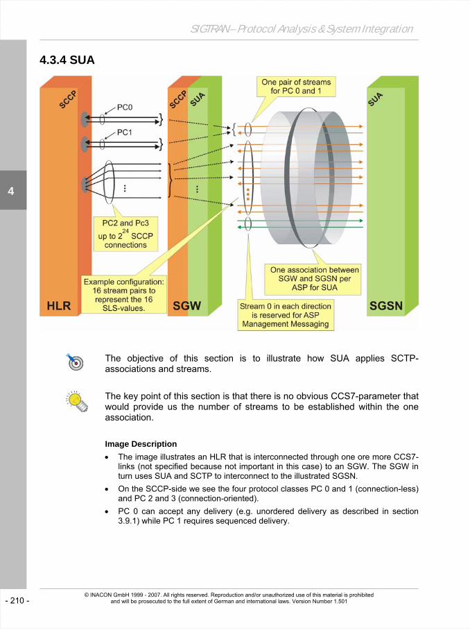
The objective of this section is to illustrate how SUA applies SCTP-associations and streams.
The key point of this section is that there is no obvious CCS7-parameter that would provide us the number of streams to be established within the one association.
Image Description • The image illustrates an HLR that is interconnected through one ore more CCS7-
links (not specified because not important in this case) to an SGW. The SGW in turn uses SUA and SCTP to interconnect to the illustrated SGSN.
• On the SCCP-side we see the four protocol classes PC 0 and 1 (connection-less) and PC 2 and 3 (connection-oriented).
• PC 0 can accept any delivery (e.g. unordered delivery as described in section 3.9.1) while PC 1 requires sequenced delivery.

- 211 -
Details of the User Adaptation Layers
4
© INACON GmbH 1999 - 2007. All rights reserved. Reproduction and/or unauthorized use of this material is prohibited and will be prosecuted to the full extent of German and international laws. Version Number 1.501
• For PC 2 and 3, altogether 224 simultaneous SCCP-connections can be established between the HLR and the SGW.
• These connection-oriented messages and the connection-less messages need to be mapped to SUA / SCTP-streams.
• For SCCP PC 0 and 1, one stream may be established with PC 0 using unordered delivery.
• For the connection-oriented protocol classes 2 and 3 it is basically the same but:
… consecutive messages of the same SCCP-connection shall be transported over the same stream. Accordingly, the mapping of connection-oriented SCCP-messages, namely the DT1-message, to a particular stream shall be related to the SLR of that connection. Still, this does not impose a certain number of streams for SUA.
Since SCCP-messages belonging to the same connection are always mapped to the same SLS it may be beneficial to establish 16+2 streams per direction: One for each SLS-value. This minimizes the risk of any head-of-line blocking. The ‘+2’ relates to one stream for PC 0 and 1 and the second one for AS-management messaging. If no CCS7-interworking is there and therefore no SLS-value can be used for load sharing then some implementation-specific mechanism shall be applied [RFC 3868 (p.105)].
• One has to consider that the theoretically optimum number of streams per direction would be 224: It would precisely fit the maximum number of possible SCCP-connections. However, the number of SCTP-streams per association is limited to 216 per direction.
• Abbreviations of this Section:
ASP Application Server Process SCTP Stream Control Transmission Protocol (RFC 2960)
CCS7 Common Channel Signaling System No. 7 (ITU-T Q-series of specifications, in particular Q.700 - Q.703)
SGSN Serving GPRS Support Node
DT1 Data Form 1 (SCCP message type) SGW Signaling Gateway
HLR Home Location Register SLR Source Local Reference
M2PA MTP-2 user Peer-to-Peer Adaptation Layer (RFC 4165)
SLS Signaling Link Selection
PC Protocol Class (SCCP) SUA SCCP User Adaptation Layer (RFC 3868)
SCCP Signaling Connection Control Part (ITU-T Q.711 - Q.714)


