454 IEEE TRANSACTIONS ON CIRCUITS AND SYSTEMS—I: REGULAR PAPERS, VOL. 53, NO. 2, FEBRUARY 2006
The Method of Double Averaging: An Approachfor Modeling Power-Factor-Correction
Switching ConvertersSiu-Chung Wong, Member, IEEE, Chi K. Tse, Fellow, IEEE, Mohamed Orabi, Member, IEEE, and
Tamotsu Ninomiya, Fellow, IEEE
Abstract—This paper describes the modeling of power-factor-correction converters under average-current-mode control, whichare widely used in switch-mode power supply applications. Theobjective is to identify stability boundaries in terms of majorcircuit parameters for facilitating design of such converters.The approach employs a double averaging procedure, whichfirst applies the usual averaging over the switching period andsubsequently applies generalized averaging over the mains period.The resulting model, after two averaging steps and applicationof a harmonic balance procedure, is nonlinear and capable ofdescribing the low-frequency nonlinear dynamics of the system.The parameter ranges within which stable operation is guaranteedcan be accurately and easily found using this model. Experimentalmeasurements are provided for verification of the analyticalresults.
Index Terms—Averaged model, closed-form stability condition,double averaging, power factor correction (PFC), switching con-verters.
I. INTRODUCTION
POWER-FACTOR-CORRECTION (PFC) boost stages arewidely used in off-line switching power supplies. The basic
configuration of a PFC boost stage consists of 1) an average-cur-rent-mode (ACM) control loop which “forces” the input cur-rent to follow the waveform of the input voltage; and 2) a slowoutput voltage feedback loop which controls the amplitude ofthe “shaped” input current according to the power demandedby the load. The aim of the control is to achieve a unity powerfactor at the input side and to maintain power balance whilekeeping the output voltage at a nearly constant level [1], [2]. Pre-viously, several attempts have been made to model the dynamicsof power converters based on dynamic phasors [3]–[5], whichcan be simplified in some specific applications to averaging andlinearization [6]–[10]. However, because the actual process is
Manuscript received March 1, 2004; revised March 11, 2005 and July 6, 2005.This work was supported by the Hong Kong Research Grants Council underGrant PolyU 5237/04E, a Research Grant on “Control of Electromagnetic En-vironment in Low-Frequency Band Below 100 kHz” of the future research pro-motion business in Japan provided by the Japan Society for Promotion of Sci-ence. This paper was recommended by Associate Editor I. A. Hiskens.
S.-C. Wong and C. K. Tse are with the Department of Electronic and In-formation Engineering, Hong Kong Polytechnic University, Hong Kong, China(e-mail: [email protected]).
M. Orabi is with the Electrical Engineering Department, Aswan Faculty ofEngineering, South Valley University, Aswan, Egypt (e-mail: [email protected]).
T. Ninomiya is with the Department of Electrical and Electronic Systems En-gineering, Kyushu University, Fukuoka 812-8581, Japan.
Digital Object Identifier 10.1109/TCSI.2005.855744
nonlinear, stability analyzes based on linearized models are veryrestricted and often provide stability information (e.g., param-eter ranges for stable operation) which are not necessarily con-sistent with reality. In particular, low-frequency period-doublingphenomena in PFC boost preregulators have been reported byOrabi et al. [11]–[13]. Also, fast-scale instability has also beenreported by Iu et al. [15]. In this paper we make use of a hi-erachical modeling approach, a basic form of which was pro-posed in [6], and apply generalized averaging together with aharmonic balance procedure to identify the low-frequency non-linear dynamics of the PFC boost converter. This method resultsin a model that is capable of revealing the phenomena foundin [11]–[13]. Essentially we apply averaging twice in succes-sion, over the switching period and the mains period, to obtaina double-averaged model in the form of a system of simple con-tinuous-time differential equations which can be readily ana-lyzed and numerically simulated. Stability information gener-ated from this model is accurate for the purpose of locating theranges of parameters within which the PFC boost converter op-erates in its normally expected regime. This technique was alsoused in Gordillo et al. [14] for the study of the dynamics ofa power factor preregulator under a special control. The workof Gordillo et al. [14], however, focuses on varying the outputvoltage. More comprehensive stability information that is pre-sented in terms of major circuit parameters is unavailable. Fur-thermore, as is common to switching converters, operation mayassume either continuous conduction mode (CCM) or discon-tinuous conduction mode (DCM). While much of the previouswork has focused on the CCM case [11]–[15], very few hasaddressed the case of DCM [16]. Moreover, the problem ofbifurcation of a supposedly CCM operation into DCM due tovariation of some parameter(s) is a complex issue, which re-quires further investigation. In this paper we restrict ourselvesto CCM operation, as it is the usual operating condition for mostof medium to high power applications.
This paper is organized as follows. In Section II, we will ex-plain the usual operation of the boost converter as employedin typical PFC applications, with emphasis on the salient op-erational conditions in the presence of a slowly varying inputvoltage. Our main proposal is described in Section III, where weexplain the mathematical technique of doubling averaging, andapply it to produce a model for the PFC boost converter underaverage current-mode control. The derivation of the steady-statesolution will be given in Section IV. Application of the double-averaged model for analysis of the stability of PFC converters
will be illustrated in Section V, where closed-form stability con-ditions are also derived. Finally, in Sections VI and VII, the sta-bility information obtained from the model will be presentedgraphically and verified by experimental measurements takenfrom a practical industrial-standard PFC converter circuit.
II. PFC BOOST CONVERTER UNDER ACM CONTROL
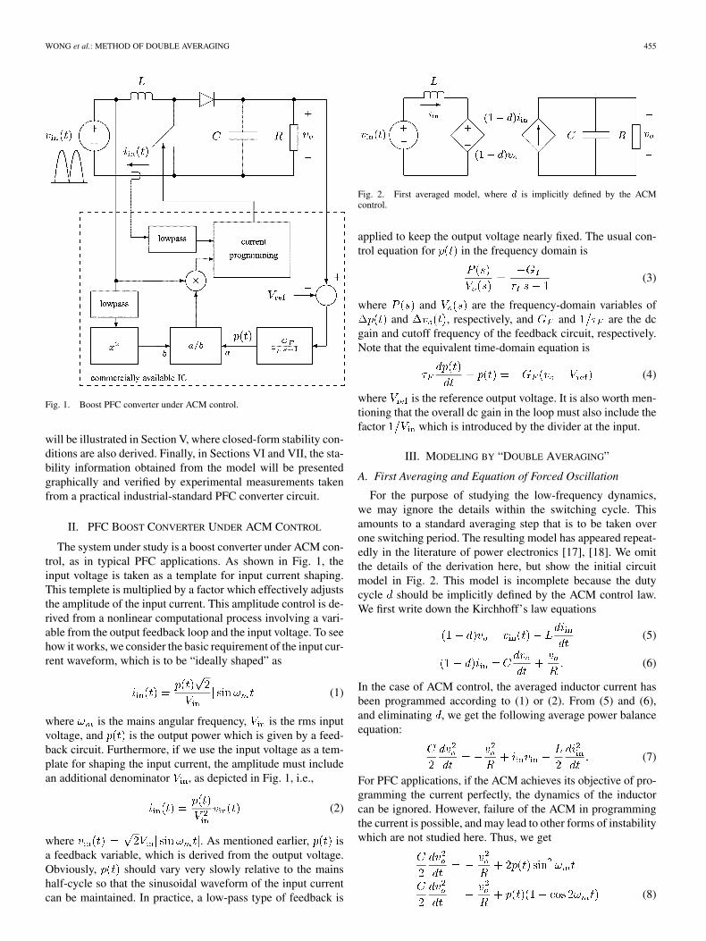
The system under study is a boost converter under ACM con-trol, as in typical PFC applications. As shown in Fig. 1, theinput voltage is taken as a template for input current shaping.This templete is multiplied by a factor which effectively adjuststhe amplitude of the input current. This amplitude control is de-rived from a nonlinear computational process involving a vari-able from the output feedback loop and the input voltage. To seehow it works, we consider the basic requirement of the input cur-rent waveform, which is to be “ideally shaped” as
(1)
where is the mains angular frequency, is the rms inputvoltage, and is the output power which is given by a feed-back circuit. Furthermore, if we use the input voltage as a tem-plate for shaping the input current, the amplitude must includean additional denominator , as depicted in Fig. 1, i.e.,
(2)
where . As mentioned earlier, isa feedback variable, which is derived from the output voltage.Obviously, should vary very slowly relative to the mainshalf-cycle so that the sinusoidal waveform of the input currentcan be maintained. In practice, a low-pass type of feedback is
Fig. 2. First averaged model, where d is implicitly defined by the ACMcontrol.
applied to keep the output voltage nearly fixed. The usual con-trol equation for in the frequency domain is
(3)
where and are the frequency-domain variables ofand , respectively, and and are the dc
gain and cutoff frequency of the feedback circuit, respectively.Note that the equivalent time-domain equation is
(4)
where is the reference output voltage. It is also worth men-tioning that the overall dc gain in the loop must also include thefactor which is introduced by the divider at the input.
III. MODELING BY “DOUBLE AVERAGING”
A. First Averaging and Equation of Forced Oscillation
For the purpose of studying the low-frequency dynamics,we may ignore the details within the switching cycle. Thisamounts to a standard averaging step that is to be taken overone switching period. The resulting model has appeared repeat-edly in the literature of power electronics [17], [18]. We omitthe details of the derivation here, but show the initial circuitmodel in Fig. 2. This model is incomplete because the dutycycle should be implicitly defined by the ACM control law.We first write down the Kirchhoff’s law equations
(5)
(6)
In the case of ACM control, the averaged inductor current hasbeen programmed according to (1) or (2). From (5) and (6),and eliminating , we get the following average power balanceequation:
(7)
For PFC applications, if the ACM achieves its objective of pro-gramming the current perfectly, the dynamics of the inductorcan be ignored. However, failure of the ACM in programmingthe current is possible, and may lead to other forms of instabilitywhich are not studied here. Thus, we get
(8)
456 IEEE TRANSACTIONS ON CIRCUITS AND SYSTEMS—I: REGULAR PAPERS, VOL. 53, NO. 2, FEBRUARY 2006
for , . It should benoted that is connected with via the feedback circuit.Therefore, (8) is a continuous-time differential equation in .
Thus, the system under study can be described by the set ofequations consisting of (4) and (8). To analyze this system, wewill make use of the fact that it describes a system of forcedoscillation, where the variables are “driven” periodically, con-taining frequency components up to twice the mains frequency.
B. Second Averaging
We now consider further application of averaging to thesystem of equations under study, which consists of (4) and (8).Specifically, we take moving average over the mains period[19]. For any variable , we may assume that it takes thefollowing form:
(9)We define each component of the moving average of , de-noted by or simply for , 1, 2, by
(10)
For brevity and without confusion, we simply write as .In other words, is the dc component of the moving averageof , is the component of the moving average of at
, and is the component of the moving average of at. Thus, we may write
(11)
where superscript denotes complex conjugation. Upon ex-panding, we get
(12)
(13)
(14)
It is readily shown that the moving average of the time-deriva-tive of each component is related to the time-derivative of thecomponent by
(15)
where denotes consistently the th component of the movingaverage, with corresponding to the dc component,
the component, and the component. Further-more, the following relations are readily obtained:
(16)
(17)
(18)
(19)
Remarks: It should be noted that the essential procedure oftaking the moving average differs from the basic double-aver-aging method of [6] where a constant steady-state point is as-sumed. Specifically, the method of [6] results in a model thatreduces all variables varying at the mains frequency to fixedsteady-state points. Thus, the subsequent small-signal analysisonly reflects stability of the mains cycle but falls short of identi-fying oscillations at other subharmonics which have been foundexperimentally. As will be shown shortly, a moving-averagedmodel, coupled with the application of a harmonic balance pro-cedure at any specific harmonic of interest, permits a quick iden-tification of forced oscillation which may occur at half, quarter,etc. of the mains frequency. A similar application was also re-ported in Gordillo et al. [14], where bifurcation resulting fromvarying the output voltage was studied. However, practical sta-bility information that is presented in terms of major circuit pa-rameters is still unavailable.
C. Derivation of the Double Averaged Model for PFC BoostConverter
In this subsection we apply the foregoing averaging to (4) and(8). We expect to get three equations from each of (4) and (8),corresponding to the dc, and components. To avoidpossible confusion due to mixup in subscripts, we define
(20)
In the following, the use of subscripts will be consistent withthe description of the second averaging in Section III-B, i.e.,subscript 0 for dc components, subscript 1 for mains frequencycomponents, and subscript 2 for twice mains frequency compo-nents. Now, application of second averaging to (8) gives
(21)
(22)
(23)
WONG et al.: METHOD OF DOUBLE AVERAGING 457
Fig. 3. Stability boundaries with: (a) G = 12:8 A, C = 60 �F, and ! = 2�(60) rad/s; (b) � = 8:6 ms, C = 60 �F, and ! = 2�(60) rad/s;(c) G = 12:8 A, C = 60 �F, and ! = 2�(60) rad/s; (d) � = 8:6 ms, G = 12:8 A, and ! = 2�(60) rad/s. Region above the boundary surface orcurve corresponds to stable operating region. At the boundary, period-doubling occurs to disrupt normal operation. Region under the boundary surface or curvecorresponds to “unstable operation” in the sense that normal operation cannot be maintained.
Note that is equal to . Moreover, (4) is decomposed into
(24)
(25)
(26)
Thus, (21)–(26) are the double averaged equations for the PFCboost converter under study.
IV. STEADY-STATE SOLUTION
To find the steady-state solution, we put all time-derivativesto zero, giving
(27)
(28)
(29)
(30)
(31)
where
(32)
Putting the above equations in (21), and using (24), we get
(33)
458 IEEE TRANSACTIONS ON CIRCUITS AND SYSTEMS—I: REGULAR PAPERS, VOL. 53, NO. 2, FEBRUARY 2006
Fig. 4. Corresponding stability boundaries with: (a) G = 128 A, C = 600 �F, and ! = 2�(60) rad/s; (b) � = 8:6 ms, C = 600 �F, and ! =2�(60) rad/s; (c) G = 128 A, C = 600 �F, and ! = 2�(60) rad/s; (d) � = 8:6 ms, G = 128 A, and ! = 2�(60) rad/s.
from which can be solved numerically. Note that is thesteady-state dc component of the output voltage, which is closeto .
V. APPLICATION OF DOUBLE AVERAGED MODEL TO
STABILITY ANALYSIS
Our purpose in this section is to examine the stability ofthe system with respect to its operation at the forcing fre-quency , which is twice the mains frequency. This isbecause the input is a rectified sine wave repeating at ,and all variables in the system are expected to repeat at thisforcing frequency. Moreover, if the system is entrapped in anorbit of frequency , i.e., at half the expected repetition fre-quency,1 the operation is considered undesirable for practicalpurposes since the device stresses would be drastically altered.
1In the literature of dynamical systems, such a change in operation isknown as period doubling, and the transition from the normal operation to adouble-period operation is typically a sudden transition. The usual term usedto describe this transition is bifurcation [20], [21].
In fact, such “period-doubling” has been observed experimen-tally when certain parameters are changed irrespective of thestability of the -orbit [11], [12]. It is therefore of prac-tical importance to locate the occurrence of period-doublingin the parameter space. In our double-averaged model, this isequivalent to finding the condition under which the system isentrapped into an -orbit.
Our approach to solve this stability problem is to considerthe loop gain of (or ) in our double averaged model. Thus,from (22) and (25), and the steady-state values solved from (28)through (31), putting the time derivatives to zero, we get the loopgain for as shown in (34) at the bottom of the next page.
The system operates at the expected forcing frequency if itis not entrapped in the -orbit, i.e., . (It turns outthat the condition is irrelevant for practical sets ofparameter values.) This condition is necessary for the system tooperate in the expected regime. We may simplify (34) by putting
, giving (35), shown at the bottom of the next page.Wenote that the condition of is equivalent to (36), alsoshown at the bottom of the next page.
WONG et al.: METHOD OF DOUBLE AVERAGING 459
Fig. 5. Schematic of experimental PFC boost converter under average current-mode control.
This means that normal operation of the circuit at can bedisrupted by period-doubling if there are parametric variationsthat violates (36). This is sometimes considered as instabilityfrom an engineering viewpoint as the system fails to operate inthe expected manner. In particular, we observe the following.
1) There is a lower limit of below which the systemcannot operate normally at the forced frequency (i.e,operating range is limited).
2) This lower limit of increases as the load resis-tance increases (i.e., normal operation is disrupted byperiod-doubling as output power decreases to a certainthreshold).
3) This lower limit of generally increases as in-creases (i.e., operating range is reduced as the feedbackgain increases).
4) This lower limit of generally increases as de-creases (i.e., operating range is reduced as the feedbacktime-constant decreases).
5) This lower limit of generally increases as theoutput capacitance decreases (i.e., operating range isreduced as output capacitance decreases).
VI. GRAPHICAL REPRESENTATIONS OF STABILITY BOUNDARIES
To help visualize the above results, we use (36) to plot a fewindicative boundary surface and curves. Our purpose is to high-light the regions in the parameter space where normal operationis expected. Figs. 3 and 4 show several operation boundaries cor-responding to some specific sets of parameters. On the boundarysurface or curves, period-doubling occurs and normal operation
(34)
(35)
(36)
460 IEEE TRANSACTIONS ON CIRCUITS AND SYSTEMS—I: REGULAR PAPERS, VOL. 53, NO. 2, FEBRUARY 2006
Fig. 6. Measured waveforms and phase portraits. (a), (b) Normal operation with R = 454 and V = 297 V; (c), (d) normal operation with R = 645 andV = 360V; (e), (f) period-doubled (unstable) operation withR = 645 and V = 297V. For all cases,G � 20A, input voltage is 100 V rms, � = 8:46ms,and line frequency is 50 Hz. For waveforms in (a), (c) and (e), upper trace is line voltage, middle trace is input current (1 A/div) and lower trace is output voltageripple. For phase portraits in (b), (d) and (f), x axis is input current and y axis is output voltage.
ceases. Region above the boundary corresponds to normal oper-ation, where the system is driven periodically at twice the mainsfrequency. These results are consistent with our observation.Specifically, the operation is stable up to a certain threshold setof parameter values. In Fig. 3, the capacitor values are relativelysmall and the output ripple is therefore relatively large, causinginstability when such a large ripple is being fed back. More-over, in Fig. 4, the capacitor values are large (normal in prac-tical sense), and instability can only occur for relatively highfeedback gain values. Our analysis provides a quantitative toolfor evaluating the stability boundaries. We will verify this toolin the next section by experiments.
VII. EXPERIMENTAL VERIFICATIONS
An experimental PFC boost converter under average currentmode control has been constructed for verification purposes. Thecomplete schematic is shown in Fig. 5. The current-shaping con-trol employs a standard 3854A integrated circuit controller. Theline frequency is 50 Hz. The input voltage is fixed at 100 V rms.
Experiments have been performed to verify the stabilityboundaries predicted in Sections V and VI. First, for a quickillustration, typical waveforms and phase portraits for normal
operation and period-doubled (unstable) operation are shownin Fig. 6.
Our main objective is to locate the parameter points whereperiod-doubling occurs. For convenience we replot the stabilitycurves along with the experimental data in Fig. 7. We clearlysee that the experimental data are in good agreement with theanalytical results.
A few practical points are worth noting here.
1) One of the determining parameters is , as shownin our analytical study. However, for measurement con-venience, we fix the input voltage in our experiments andvary the output voltage.
2) In our analytical model, the feedback loop is defined bytwo parameters, namely and . In order to find thecorresponding value of for the experimental circuit,we have to carefully identify all gains that may possiblycontribute to since the model assumes no gain in themultiplier-divider block. In our experiment, we find thisgain by direct measurement.
3) Our definition of is the real time constant. Thus, itsreciprocal should be compared directly with the angularmains frequency in rad/s instead of the frequency in
WONG et al.: METHOD OF DOUBLE AVERAGING 461
Fig. 7. Measured stability boundaries taken at V = 100 V (rms) and 50 Hz line frequency. Experimental data points are plotted as dots. Solid curves are fromanalytical expressions. (a) C = 69 �F and � = 8:46 ms; (b) C = 69 �F and G = 17:46 A; (c) G = 17:46 A and � = 8:46 ms. Note that the y axiswould have been v =V for better generality, as shown in our analytical study. However, for measurement convenience, we have fixed the input voltage in ourexperiments and varied the output voltage.
Hertz. For instance, ms refersto a time constant equal to the period of a 50 Hz signal.
4) We have performed the experiments for relatively smalloutput capacitor values in order to allow instability to beseen with the usual gain values readily implementable bythe particular controller UC3854A. However, we shouldstress that the phenomenon remains invariant for prac-tical capacitor values (e.g., hundreds of F) provided thathigher feedback gain values are used accordingly, as perFig. 4 or (36).
VIII. CONCLUSION
At present, the main technique for the analysis of powerconverters is based on averaging and subsequent small-signallinearization. Since PFC converters are subject to a time-varyinginput voltage and the current-shaping process is nonlinear, theresults obtained from small-signal linear analysis have limitedvalidity and often provide inaccurate stability information, ashas been explained and demonstrated by Orabi et al. [11]–[13]with computer simulations and laboratory measurements.Nonlinear analytical models would be desirable for stabilityevaluation. This paper has applied a method of double averagingfor modeling PFC converters, leading to nonlinear models from
which closed-form stability conditions can be derived. Thismethod is capable of revealing the low-frequency stability of thecircuit. For instability near the switching frequency, moreover,we need a different type of models, such as those based ondiscrete-time mapping [15], [22], for revealing the fast-scaleinstability.
ACKNOWLEDGMENT
The authors wish to express their gratitude to the reviewersfor drawing their attention to [6] and [14], and to one re-viewer for clarifying the issue of omitting the inductor currentdynamics.
REFERENCES
[1] L. H. Dixon, Jr., “High power factor preregulator for off-line powersupplies,” in Unitrode Switching Regulated Power Supply DesignManual. Merrimack, NH: Unitrode Corp., 1990.
[2] R. Redl, “Power-factor-correction in single-phase switching-modepower supplies—An overview,” Int. J. Electron., vol. 77, no. 5, pp.555–582, 1994.
[3] P. C. Stefanov and A. M. Stankovic, “Modeling of UPFC operation underunbalanced conditions with dynamic phasors,” IEEE Trans. Power Syst.,vol. 17, no. 2, pp. 395–403, May 2002.
[4] A. M. Stankovic, S. R. Sanders, and T. Aydin, “Dynamic phasors inanalysis of unbalanced polyphase ac machines,” IEEE Trans. EnergyConvers., vol. 17, no. 1, pp. 107–113, Mar. 2002.
462 IEEE TRANSACTIONS ON CIRCUITS AND SYSTEMS—I: REGULAR PAPERS, VOL. 53, NO. 2, FEBRUARY 2006
[5] D. Maksimovic, A. M. Stankovic, V. J. Thottuvelil, and G. C. Verghese,“Modeling and simulation of power electronic converters,” Proc. IEEE,vol. 89, no. 6, pp. 898–912, Jun. 2001.
[6] V. J. Thottuvelil, D. Chin, and G. Verghese, “Hierachical approachesto modeling high-power-factor AC-DC converters,” IEEE Trans. PowerElectron., vol. 6, no. 2, pp. 179–187, Apr. 1991.
[7] G. Zhu, H. Wei, P. Kornetzky, and I. Batarseh, “Small-signal modeling ofa single-switch AC/DC power factor correction circuit,” in IEEE PowerElectron. Specialists Conf. Rec., Fukuoka, Japan, 1998, pp. 601–607.
[8] G. Zhu, C. Iannello, P. Kornetzky, and I. Batarseh, “Large-signalmodeling of a single-switch power factor correction converter,” in IEEEPower Electron. Specialists Conf. Rec., Galway, Ireland, 2000, pp.1351–1357.
[9] V. S. Murali, C. K. Tse, and M. H. L. Chow, “Small-signal analysis ofsingle-stage cascaded boost-and-buck PFC converters,” in IEEE PowerElectron. Specialists Conf. Rec., Fukuoka, Japan, 1998, pp. 608–614.
[10] M. Shen and Z. Qian, “A unified average model for single stage and twostage power factor correction converters,” in Proc. Appl. Power Electron.Conf. Expo., 2001, pp. 125–129.
[11] M. Orabi, T. Ninomiya, and C. Jin, “Nonlinear dynamics and stabilityanalyzes of boost power-factor-correction circuit,” in Proc. Int. Conf.Power Syst. Tech., 2002, pp. 600–605.
[12] , “A novel modeling of instability phenomena in PFC converter,”in Proc. IEEE Int. Telecommun. Energy Conf., 2002, pp. 566–573.
[13] M. Orabi and T. Ninomiya, “Nonlinear dynamics of power-factor-cor-rection converter,” IEEE Trans. Ind. Electron., vol. 50, no. 6, pp.1116–1125, Dec. 2003.
[14] F. Gordillo, G. Escobar, and J. Aracil, “Bifurcation analysis of a powerfactor precompensator,” in Stability and Stabilization of Nonlinear Sys-tems. London, U.K.: Springer-Verlag, 1999.
[15] H. H. C. Iu, Y. Zhou, and C. K. Tse, “Fast-scale instability in a PFC boostconverter under average current mode control,” Int. J. Circuit TheoryAppl., vol. 31, no. 6, pp. 611–624, 2003.
[16] X. Wu, C. K. Tse, O. Dranga, and J. Lu, “Fast-scale instability ofsingle-stage power-factor-correction power supplies,” IEEE Trans.Circuits Syst. I, vol. 53, no. 1, pp. 204–213, Jan. 2006.
[17] R. D. Middlebrook and S. Cuk, “A general unified approach to modelingswitching-converter power stages,” in IEEE Power Electron. Spec. Conf.Rec., Pasadena, CA, 1976, pp. 18–34.
[18] C. K. Tse, Y. S. Lee, and W. C. So, “An approach to modeling DC-DCconverters using graph theoretic concepts,” Int. J. Circuit Theory Appl.,vol. 21, no. 4, pp. 371–384, 1993.
[19] S. R. Sanders, J. M. Noworolski, X. Z. Liu, and G. Verghese, “General-ized averaging method for power electronic circuits,” IEEE Trans. PowerElectron., vol. 6, no. 2, pp. 251–259, Mar. 1991.
[20] S. Banerjee and G. Verghese, Eds., Nonlinear Phenomena in PowerElectronics: Attractors, Bifurcations, Chaos and Nonlinear Con-trol. New York: IEEE Press, 2001.
[21] C. K. Tse, Complex Behavior of Switching Power Converters. BocaRaton, FL: CRC Press, 2003.
[22] O. Dranga, C. K. Tse, H. H. C. Iu, and I. Nagy, “Bifurcation behavior inpower-factor-correction boost converter,” Int. J. Bifurc. Chaos, vol. 13,no. 10, pp. 3107–3114, 2003.
Siu-Chung Wong (M’01) received the B.Sc. degreein physics from the University of Hong Kong, HongKong, the M.Phil. degree in electronics from the Chi-nese University of Hong Kong, Hong Kong, and thePh.D. degree from the University of Southampton,Southampton, U.K., in in 1986, 1989, and 1997,respectively.
He is currently an Assistant Professor in the De-partment of Electronic and Information Engineeringat Hong Kong Polytechnic University, Hong Kong.His research interests include modeling of power
converters, nonlinear analysis of power electronics and Internet traffic analysis.Dr. Wong is a member of the Electrical College, The Institution of Engineers,
Australia.
Chi K. Tse (M’90–SM’97–F’06) received the B.Eng.(Hons) degree with first class honors in electrical en-gineering and the Ph.D. degree from the University ofMelbourne, Melbourne, Australia, in 1987 and 1991,respectively.
He is presently Chair Professor of Electronic En-gineering at the Hong Kong Polytechnic University,Hong Kong, and his research interests include chaoticdynamics and power electronics. He is the authorof Linear Circuit Analysis (Reading, MA: Addison-Wesley, 1998) and Complex Behavior of Switching
Power Converters (Boca Raton, FL: CRC Press, 2003), and co-author of Chaos-Based Digital Communication Systems (New York: Springer-Verlag, 2003)and Signal Reconstruction With Applications to Chaos-Based Communications(Beijing, China: Tsinghua University Press, 2005), and co-holder of a U.S.patent.
Dr. Tse served as an Associate Editor for the IEEE TRANSACTIONS ONCIRCUITS AND SYSTEMS—I: FUNDAMENTAL THEORY AND APPLICATIONSfrom 1999 to 2001, and since 1999, he has been an Associate Editor for theIEEE TRANSACTIONS ON POWER ELECTRONICS. He currently also serves asan Associate Editor for the International Journal of Systems Science, a GuestAssociate Editor of the IEICE Transactions on Fundamentals of Electronics,Communications and Computers, and a Guest Editor of Circuits, Systems andSignal Processing. He was awarded the L.R. East Prize by the Institution ofEngineers, Australia, in 1987. He won the IEEE TRANSACTIONS ON POWERELECTRONICS Prize Paper Award for 2001 and the International Journal ofCircuit Theory and Applications Best Paper Award for 2003. In 2005, he wasappointed an IEEE Distinguished Lecturer. While with Hong Kong PolytechnicUniversity, he twice received the President’s Award for Achievement in Re-search, the Faculty’s Best Researcher Award, the Research Grant AchievementAward, and a few other teaching awards.
Mohamed Orabi (S’02–M’04) was born in Kena,Egypt, in 1974. He received the B.Sc. and M.Sc.degrees in electrical engineering from ElminiaUniversity, Elminia, Egypt, in 1996 and 2000, re-spectively, and the Ph.D. degree in power electronicsfrom Kyushu University, Fukuoka, Japan, in 2004.
He has been with the Department of ElectricalEngineering, Aswan Faculty of Engineering, SouthValley University, Aswan, Egypt, first as an Ad-ministrator from 1996 to 2000, then as ResearchAssistant from 2000 to 2004, and as an Assistant
Professor since 2004. His research interests include developing and designingswitched-mode power converters, applications to power factor correction, sta-bility problems, nonlinear phenomena, chaos, and period doubling bifurcation.He has authored more than 30 published papers.
Dr. Orabi received the 2002 Excellent Student Award of the IEEE FukuokaSection, the Best Paper Award of 28th Annual Conference of the IEEE Indus-trial Electronics Society in 2002, the IEEE IES Student Grant from 2003 IEEEInternational Symposium on Industrial Electronics, and the IEICE Best YoungResearcher Award for 2004.
Tamotsu Ninomiya (M’89–SM’98–F’01) receivedthe B.E., M.E., and Dr. Eng. degrees in electronicsfrom Kyushu University, Fukuoka, Japan, in 1967,1969, and 1981, respectively.
Since 1969, he has been with the Department ofElectronics, Kyushu University, first as a ResearchAssistant and, since 1988, as a Full Professor. Sincethe reorganization in 1996, he has been a Professorin the Department of Electrical and Electronic Sys-tems Engineering of the Graduate School of Infor-mation Science and Electrical Engineering. He is a
specialist in the field of power electronics, including the analysis of switchingpower converters and their electromagnetic interference problems, the develop-ment of noise-suppression techniques, and piezoelectric transformer converters.He has authored about 200 published technical papers.
Prof. Ninomiya has served as a Member of the Program Committee and Ses-sion Chairman of the IEEE Power Electronics Specialist Conference (PESC)sponsored by the IEEE Power Electronics Society (PELS) for many years. Hewas Program Vice-Chairman for the 1988 PESC and General Chairman for the1998 PESC. He was a Member of the Administrative Committee of the IEEEPELS from 1993 through 1998. He served as Chairman of the ProfessionalGroup on High-Frequency Applied Magnetics of the Institute of Electrical Engi-neers of Japan, and as Chairman of the Technical Group on Power Engineeringin Electronics and Communications of the Institute of Electronics, Information,and Communication Engineers of Japan.


![IEEE TRANSACTIONS ON CIRCUITS AND SYSTEMS …ssl.kaist.ac.kr/2007/data/journal/[2010_TCSVT]JooYoungKim.pdf · IEEE TRANSACTIONS ON CIRCUITS AND SYSTEMS FOR VIDEO TECHNOLOGY, VOL.](https://static.documents.pub/doc/80x56/5aa3c0047f8b9a84398ec6d7/ieee-transactions-on-circuits-and-systems-sslkaistackr2007datajournal2010tcsvt.jpg)
