[Page 420 (continued)] 4.7. Overview of the MINIX 3 Process Manager Memory managementin MINIX 3 is simple: pagingis not used at all. MINIX 3 memory managementas we will discuss it here does not include swapping either.Swappingcode is available in the complete source and could be activated to make MINIX 3 work on a system with limited physical memory. In practice, memories are so large now that swapping is rarely needed. In this chapter we will study a user-space server designatedthe process manager, or PM for short. The process manager handles system calls relating to process management.Of these some are intimately involved with memory management.The fork , exec , and brk calls are in this category.Process managementalso includes processing system calls related to signals, setting and examiningprocess properties such as user and group ownership, and reporting CPU usage times. The MINIX 3 process manager also handles setting and queryingthe real time clock. Sometimes when we are referring to that part of the process manager that handles memory management,we will refer to it as the "memory manager." It is possible that in a future release, process managementand memory managementwill be completely separated, but in MINIX 3 the two functions are merged into one process. The PM maintains a list of holes sorted in numerical memory address order.When memory is needed, either due to a fork or an exec system call, the hole list is searched using first fit for a hole that is big enough. Without swapping, a process that has been placed in memory remains in exactly the same place during its entire execution.It is never moved to another place in memory, nor does its allocated memory area ever grow or shrink. [Page 421] This strategy for managingmemory is somewhat unusual and deserves some explanation. It was originally derived from three factors: 1. The desire to keep the system easy to understand. 2. The architecture of the original IBM PC CPU (an Intel 8088), 3. The goal of making MINIX 3 easy to port to other hardware, First, as a teaching system, avoidingcomplexity was highly desirable; a source code listing of nearly 250 pages was deemed long enough. Second,the system was designedfor the original IBM PC, which did not even have an MMU, so includingpagingwas impossible to start with. Third, since other computers of its era also lacked MMUs, this memory managementstrategy made porting to the Macintosh, Atari, Amiga, and other machines easier. Of course, one can rightly ask if such a strategy still makes sense. The first point is still valid, althoughthe system has definitely grown over the years. However, several new factors also play a role now.Modern PCs have more than 1000times as much memory available as the original IBM PC. While programs are bigger,most systems have so much memory that swapping and pagingare hardly needed. Finally, MINIX 3 is targeted to some extent at low-end systems such as embedded systems. Nowadays, digital cameras, DVD players, stereos, cell phones,and other products have operatingsystems, but certainly do not support swapping or paging.MINIX 3 is quite a reasonablechoice in this world, so swapping and pagingare not a high priority. Nevertheless, some work is in progress to see what can be done in the area of virtual memory in the simplest possible way. The Web site should be consulted to follow current developments. It is also worth pointingout another way in which implementation of memory managementin MINIX 3 differs from that of many other operatingsystems. The PM is not part of the kernel. Instead, it is a process that runs in user space and communicates with the kernel by the standard message mechanism. The position of the PM is shown in Fig. 2-29 . Moving the PM out of the kernel is an example of the separation of policy and mechanism. The decisions about which process will be placed where in memory (policy) are made by the PM. The actual setting of memory maps for processes (mechanism) is done by the system task within the kernel. This split makes it relatively easy to changethe memory managementpolicy (algorithms, etc.) without havingto modify the lowest layers of the operatingsystem. Most of the PM code is devotedto handling the MINIX 3 system calls that involve creating processes, primarily fork and exec , rather than just manipulatinglists of processes and holes. In the next section we will look at the memory layout, and in subsequent sections we will take a bird's-eye view of how the process managementsystem calls are handledby the PM. [Page 422] 4.7.1. Memory Layout MINIX 3 programs may be compiled to use combined I and D space, in which all parts of the process (text, data, and stack) share a block of memory which is allocated and released as one block. This was the default for the original version of MINIX. In MINIX 3, however, the default is to compile programs to use separate I and D space. For clarity, allocation of memory for the simpler
Transcript
[Page 420 (continued)]
4.7. Overview of the MINIX 3 Process ManagerMemory management in MINIX 3 is simple: paging is not used at all. MINIX 3 memory management as we will discuss it here does not include swapping either. Swapping code is available in the complete source and could be activated to make MINIX 3 work on a system with limited physical memory. In practice, memories are so large now that swapping is rarely needed.
In this chapter we will study a user-space server designated the process manager, or PM for short. The process manager handles system calls relating to process management. Of these some are intimately involved with memory management. The fork, exec, and brk calls are in this category. Process management also includes processing system calls related to signals, setting and examining process properties such as user and group ownership, and reporting CPU usage times. The MINIX 3 process manager also handles setting and querying the real time clock.
Sometimes when we are referring to that part of the process manager that handles memory management, we will refer to it as the "memory manager." It is possible that in a future release, process management and memory management will be completely separated, but in MINIX 3 the two functions are merged into one process.
The PM maintains a list of holes sorted in numerical memory address order. When memory is needed, either due to a fork or an exec system call, the hole list is searched using first fit for a hole that is big enough. Without swapping, a process that has been placed in memory remains in exactly the same place during its entire execution. It is never moved to another place in memory, nor does its allocated memory area ever grow or shrink.
[Page 421]
This strategy for managing memory is somewhat unusual and deserves some explanation. It was originally derived from three factors:
1. The desire to keep the system easy to understand.
2. The architecture of the original IBM PC CPU (an Intel 8088),
3. The goal of making MINIX 3 easy to port to other hardware,
First, as a teaching system, avoiding complexity was highly desirable; a source code listing of nearly 250 pages was deemed long enough. Second, the system was designed for the original IBM PC, which did not even have an MMU, so including paging was impossible to start with. Third, since other computers of its era also lacked MMUs, this memory management strategy made porting to the Macintosh, Atari, Amiga, and other machines easier.
Of course, one can rightly ask if such a strategy still makes sense. The first point is still valid, although the system has definitely grown over the years. However, several new factors also play a role now. Modern PCs have more than 1000 times as much memory available as the original IBM PC. While programs are bigger, most systems have so much memory that swapping and paging are hardly needed. Finally, MINIX 3 is targeted to some extent at low-end systems such as embedded systems. Nowadays, digital cameras, DVD players, stereos, cell phones, and other products have operating systems, but certainly do not support swapping or paging. MINIX 3 is quite a reasonable choice in this world, so swapping and paging are not a high priority. Nevertheless, some work is in progress to see what can be done in the area of virtual memory in the simplest possible way. The Web site should be consulted to follow current developments.
It is also worth pointing out another way in which implementation of memory management in MINIX 3 differs from that of many other operating systems. The PM is not part of the kernel. Instead, it is a process that runs in user space and communicates with the kernel by the standard message mechanism. The position of the PM is shown in Fig. 2-29.
Moving the PM out of the kernel is an example of the separation of policy and mechanism. The decisions about which process will be placed where in memory (policy) are made by the PM. The actual setting of memory maps for processes (mechanism) is done by the system task within the kernel. This split makes it relatively easy to change the memory management policy (algorithms, etc.) without having to modify the lowest layers of the operating system.
Most of the PM code is devoted to handling the MINIX 3 system calls that involve creating processes, primarily fork and exec, rather than just manipulating lists of processes and holes. In the next section we will look at the memory layout, and in subsequent sections we will take a bird's-eye view of how the process management system calls are handled by the PM.
[Page 422]
4.7.1. Memory Layout
MINIX 3 programs may be compiled to use combined I and D space, in which all parts of the process (text, data, and stack) share a block of memory which is allocated and released as one block. This was the default for the original version of MINIX. In MINIX 3, however, the default is to compile programs to use separate I and D space. For clarity, allocation of memory for the simpler
however, the default is to compile programs to use separate I and D space. For clarity, allocation of memory for the simpler combined model will be discussed first. Processes using separate I and D space can use memory more efficiently, but taking advantage of this feature complicates things. We will discuss the complications after the simple case has been outlined.
In normal MINIX 3 operation memory is allocated on two occasions. First, when a process forks, the amount of memory needed by the child is allocated. Second, when a process changes its memory image via the exec system call, the space occupied by the old image is returned to the free list as a hole, and memory is allocated for the new image. The new image may be in a part of memory different from the released memory. Its location will depend upon where an adequate hole is found. Memory is also released whenever a process terminates, either by exiting or by being killed by a signal. There is a third case: a system process can request memory for its own use; for instance, the memory driver can request memory for the RAM disk. This can only happen during system initialization.
Figure 4-30 shows memory allocation during a fork and an exec. In Fig. 4-30(a) we see two processes, A and B, in memory. If A forks, we get the situation of Fig. 4-30(b). The child is an exact copy of A. If the child now execs the file C, the memory looks like Fig. 4-30(c). The child's image is replaced by C.
Figure 4-30. Memory allocation. (a) Originally. (b) After a fork. (c) After the child does an exec. The shaded regions are unused memory. The process is a common I&D one.
Note that the old memory for the child is released before the new memory for C is allocated, so that C can use the child's memory. In this way, a series of fork and exec pairs (such as the shell setting up a pipeline) can result in all the processes being adjacent, with no holes between them, assuming a large block of unallocated memory exists. Holes would remain if the new memory had been allocated before the old memory had been released.
[Page 423]
Doing it this way is not trivial. Consider the possible error condition that there is not enough memory to perform an exec. A test for sufficient memory to complete the operation should be performed before the child's memory is released, so the child can respond to the error somehow. This means the child's memory must be considered as if it were a hole while it is still in use.
When memory is allocated, either by the fork or exec system calls, a certain amount of it is taken for the new process. In the former case, the amount taken is identical to what the parent process has. In the latter case, the PM takes the amount specified in the header of the file executed. Once this allocation has been made, under no conditions is the process ever allocated any more total memory.
What has been said so far applies to programs that have been compiled with combined I and D space. Programs with separate I and D space take advantage of an enhanced mode of memory management called shared text. When such a process does a fork, only the amount of memory needed for a copy of the new process' data and stack is allocated. Both the parent and the child share the executable code already in use by the parent. When such a process does an exec, the process table is searched to see if another process is already using the executable code needed. If one is found, new memory is allocated only for the data and stack, and the text already in memory is shared. Shared text complicates termination of a process. When a process terminates it always releases the memory occupied by its data and stack. But it only releases the memory occupied by its text segment after a search of the process table reveals that no other current process is sharing that memory. Thus a process may be allocated more memory when it starts than it releases when it terminates, if it loaded its own text when it started but that text is being shared by one or more other processes when the first process terminates.
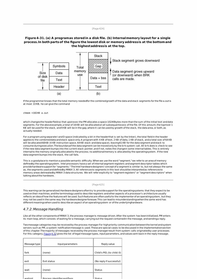
Figure 4-31 shows how a program is stored as a disk file and how this is transferred to the internal memory layout of a MINIX 3 process. The header on the disk file contains information about the sizes of the different parts of the image, as well as the total size. In the header of a program with common I and D space, a field specifies the total size of the text and data parts; these parts are copied directly to the memory image. The data part in the image is enlarged by the amount specified in the bss field in the header. This area is cleared to contain all zeroes and is used for uninitialized static data. The total amount of memory to be allocated is specified by the total field in the header. If, for example, a program has 4 KB of text, 2 KB of data plus bss, and 1 KB of stack, and the header says to allocate 40 KB total, the gap of unused memory between the data segment and the stack segment will be 33 KB. A program file on the disk may also contain a symbol table. This is for use in debugging and is not copied into memory.
[Page 424]
Figure 4-31. (a) A program as stored in a disk file. (b) Internal memory layout for a single process. In both parts of the figure the lowest disk or memory address is at the bottom and
the highest address is at the top.
If the programmer knows that the total memory needed for the combined growth of the data and stack segments for the file a.out is at most 10 KB, he can give the command
chmem =10240 a.out
which changes the header field so that upon exec the PM allocates a space 10240 bytes more than the sum of the initial text and data segments. For the above example, a total of 16 KB will be allocated on all subsequent execs of the file. Of this amount, the topmost 1 KB will be used for the stack, and 9 KB will be in the gap, where it can be used by growth of the stack, the data area, or both, as actually needed.
For a program using separate I and D space (indicated by a bit in the header that is set by the linker), the total field in the header applies to the combined data and stack space only. A program with 4 KB of text, 2 KB of data, 1 KB of stack, and a total size of 64 KB will be allocated 68 KB (4 KB instruction space, 64 KB stack and data space), leaving 61 KB for the data segment and stack to consume during execution. The boundary of the data segment can be moved only by the brk system call. All brk does is check to see if the new data segment bumps into the current stack pointer, and if not, notes the change in some internal tables. This is entirely internal to the memory originally allocated to the process; no additional memory is allocated by the operating system. If the new data segment bumps into the stack, the call fails.
This is a good place to mention a possible semantic difficulty. When we use the word "segment," we refer to an area of memory defined by the operating system. Intel processors have a set of internal segment registers and segment descriptor tables which provide hardware support for "segments." The Intel hardware designers' concept of a segment is similar to, but not always the same as, the segments used and defined by MINIX 3. All references to segments in this text should be interpreted as references to memory areas delineated by MINIX 3 data structures. We will refer explicitly to "segment registers" or "segment descriptors" when talking about the hardware.
[Page 425]
This warning can be generalized. Hardware designers often try to provide support for the operating systems that they expect to be used on their machines, and the terminology used to describe registers and other aspects of a processor's architecture usually reflects an idea of how the features will be used. Such features are often useful to the implementer of an operating system, but they may not be used in the same way the hardware designer foresaw. This can lead to misunderstandings when the same word has different meanings when used to describe an aspect of an operating system or of the underlying hardware.
4.7.2. Message Handling
Like all the other components of MINIX 3, the process manager is message driven. After the system has been initialized, PM enters its main loop, which consists of waiting for a message, carrying out the request contained in the message, and sending a reply.
Two message categories may be received by the process manager. For high priority communication between the kernel and system servers such as PM, a system notification message is used. These are special cases to be discussed in the implementation section of this chapter. The majority of messages received by the process manager result from system calls originated by user processes. For this category, Figure 4-32 gives the list of legal message types, input parameters, and values sent back in the reply message.
Message type Input parameters Reply value
fork (none) Child's PID, (to child: 0)
exit Exit status (No reply if successful)
wait (none) Status
waitpid Process identifier and flags Status
brk New size New size
exec Pointer to initial stack (No reply if successful)
kill Process identifier and signal Status
alarm Number of seconds to wait Residual time
pause (none) (No reply if successful)
sigaction Signal number, action, old action Status
sigsuspend Signal mask (No reply if successful)
sigpending (none) Status
sigprocmask How, set, old set Status
sigreturn Context Status
getuid (none) Uid, effective uid
getgid (none) Gid, effective gid
getpid (none) PID, parent PID
setuid New uid Status
setgid New gid Status
setsid New sid Process group
getpgrp New gid Process group
time Pointer to place where current time goes Status
stime Pointer to current time Status
times Pointer to buffer for process and child times Uptime since boot
ptrace Request, PID, address, data Status
reboot How (halt, reboot, or panic) (No reply if successful)
svrctl Request, data (depends upon function) Status
getsysinfo Request, data (depends upon function) Status
getprocnr (none) Proc number
memalloc Size, pointer to address Status
memfree Size, address Status
getpriority Pid, type, value Priority (nice value)
setpriority Pid, type, value Priority (nice value)
gettimeofday (none) Time, uptime
Figure 4-32. The message types, input parameters, and reply values used for communicating with the PM.
(This item is displayed on page 427 in the print version)
Fork, exit, wait, waitpid, brk, and exec are clearly closely related to memory allocation and deallocation. The calls kill, alarm, and pause are all related to signals, as are sigaction, sigsuspend, sigpending, sigmask, and sigreturn. These also can affect what is in memory, because when a signal kills a process the memory used by that process is deallocated. The seven get/set calls have nothing to do with memory management at all, but they certainly relate to process management. Other calls could go either in the file system or the PM, since every system call is handled by one or the other. They were put here simply because the file system was large enough already. The time, stime, and times calls were put here for this reason, as was ptrace, which is used in debugging.
Reboot has effects throughout the operating system, but its first job is to send signals to terminate all processes in a controlled way, so the PM is a good place for it. The same is true of svrctl, whose most important use is to enable or disable swapping in the PM.
You may have noticed that the last two calls mentioned here, reboot and svrctl, were not listed in Fig. 1-9. This also true of the remaining calls in Fig. 4-32, getsysinfo, getprocnr, memalloc, memfree, and getsetpriority. None of these are intended for use by ordinary user processes, and they are not parts of the POSIX standard. They are provided because they are needed in a system like MINIX 3. In a system with a monolithic kernel the operations provided by these calls could be provided by calls to functions compiled into the kernel. But in MINIX 3 components that are normally considered part of the operating system run in user space, and additional system calls are needed. Some of these do little more than implement an interface to a kernel call, a term we use for calls that request kernel services via the system task.
[Page 426]
As mentioned in Chap. 1, although there is a library routine sbrk, there is no system call sbrk. The library routine computes the amount of memory needed by adding the increment or decrement specified as parameter to the current size and makes a brk call to set the size. Similarly, there are no separate system calls for geteuid and getegid. The calls getuid and getgid return both the effective and real identifiers. In like manner, getpid returns the PID of both the calling process and its parent.
A key data structure used for message processing is the call_vec table declared in table.c. It contains pointers to the procedures that handle the various message types. When a message comes in to the PM, the main loop extracts the message type and puts it in the global variable call_nr. This value is then used to index into call_vec to find the pointer to the procedure that handles the newly arrived message. That procedure is then called to execute the system call. The value that it returns is sent back to the caller in the reply message to report on the success or failure of the call. The mechanism is similar to the table of pointers to system call handlers used in step 7 of Fig. 1-16, only in user space rather than in the kernel.
4.7.3. Process Manager Data Structures and Algorithms
Two key data structures are used by the process manager: the process table and the hole table. We will now look at each of these in turn.
In Fig. 2-4 we saw that some process table fields are needed by the kernel, others by the process manager, and yet others by the file system. In MINIX 3, each of these three pieces of the operating system has its own process table, containing just those fields that it needs. With a few exceptions, entries correspond exactly, to keep things simple. Thus, slot k of the PM's table refers to the same process as slot k of the file system's table. When a process is created or destroyed, all three parts update their tables to reflect the new situation, in order to keep them synchronized.
The exceptions are processes that are not known outside of the kernel, either because they are compiled into the kernel, like the CLOCK and SYSTEM tasks, or because they are place holders like IDLE, and KERNEL. In the kernel process table their slots are designated by negative numbers. These slots do not exist in the process manager or file system process tables. Thus, strictly speaking, what was said above about slot k in the tables is true for k equal to or greater than zero.
[Page 428]
Processes in Memory
The PM's process table is called mproc and its definition is given in src/servers/pm/mproc.h. It contains all the fields related to a process' memory allocation, as well as some additional items. The most important field is the array mp_seg, which has three entries, for the text, data, and stack segments, respectively. Each entry is a structure containing the virtual address, physical address, and length of the segment, all measured in clicks rather than in bytes. The size of a click is implementation dependent. In early MINIX versions it was 256 bytes. For MINIX 3 it is 1024 bytes. All segments must start on a click boundary and occupy an integral number of clicks.
The method used for recording memory allocation is shown in Fig. 4-33. In this figure we have a process with 3 KB of text, 4 KB of data, a gap of 1 KB, and then a 2-KB stack, for a total memory allocation of 10 KB. In Fig. 4-33(b) we see what the virtual, physical, and length fields for each of the three segments are, assuming that the process does not have separate I and D space. In this model, the text segment is always empty, and the data segment contains both text and data. When a process references virtual address 0, either to jump to it or to read it (i.e., as instruction space or as data space), physical address 0x32000 (in decimal, 200K) will be used. This address is at click 0xc8.
Figure 4-33. (a) A process in memory. (b) Its memory representation for combined I and D space. (c) Its memory representation for separate I and D space.
Note that the virtual address at which the stack begins depends initially on the total amount of memory allocated to the process. If the chmem command were used to modify the file header to provide a larger dynamic allocation area (bigger gap between data and stack segments), the next time the file was executed, the stack would start at a higher virtual address. If the stack grows longer by one click, the stack entry should change from the triple (0x8, 0xd0, 0x2) to the triple (0x7, 0xcf, 0x3). Note that, in this example, growth of the stack by one click would reduce the gap to nothing if there were no increase of the total memory allocation.
[Page 429]
The 8088 hardware does not have a stack limit trap, and MINIX defined the stack in a way that will not trigger the trap on 32-bit processors until the stack has already overwritten the data segment. Thus, this change will not be made until the next brk system call, at which point the operating system explicitly reads SP and recomputes the segment entries. On a machine with a stack trap, the stack segment's entry could be updated as soon as the stack outgrew its segment. This is not done by MINIX 3 on 32-bit Intel processors, for reasons we will now discuss.
We mentioned previously that the efforts of hardware designers may not always produce exactly what the software designer needs. Even in protected mode on a Pentium, MINIX 3 does not trap when the stack outgrows its segment. Although in protected mode the Intel hardware detects attempted access to memory outside a segment (as defined by a segment descriptor such as the one in Fig. 4-26), in MINIX 3 the data segment descriptor and the stack segment descriptor are always identical. The MINIX 3 data and stack segments each use part of this space, and thus either or both can expand into the gap between them. However, only MINIX 3 can manage this. The CPU has no way to detect errors involving the gap, since as far as the hardware is concerned the gap is a valid part of both the data area and the stack area. Of course, the hardware can detect a very large error, such as an attempt to access memory outside the combined data-gap-stack area. This will protect one process from the mistakes of another process but is not enough to protect a process from itself.
A design decision was made here. We recognize an argument can be made for abandoning the shared hardware-defined segment that allows MINIX 3 to dynamically reallocate the gap area. The alternative, using the hardware to define nonoverlapping stack and data segments, would offer somewhat more security from certain errors but would make MINIX 3 more memory-hungry. The source code is available to anybody who wants to evaluate the other approach.
Fig. 4-33(c) shows the segment entries for the memory layout of Fig. 4-33(a) for separate I and D space. Here both the text and data segments are nonzero in length. The mp_seg array shown in Fig. 4-33(b) or (c) is primarily used to map virtual addresses onto physical memory addresses. Given a virtual address and the space to which it belongs, it is a simple matter to see whether the virtual address is legal or not (i.e., falls inside a segment), and if legal, what the corresponding physical address is. The kernel procedure umap_local performs this mapping for the I/O tasks and for copying to and from user space, for example.
[Page 430]
Shared Text
The contents of the data and stack areas belonging to a process may change as the process executes, but the text does not change. It is common for several processes to be executing copies of the same program, for instance several users may be executing the same shell. Memory efficiency is improved by using shared text. When exec is about to load a process, it opens the file holding the disk image of the program to be loaded and reads the file header. If the process uses separate I and D space, a search of the mp_dev, mp_ino, and mp_ctime fields in each slot of mproc is made. These hold the device and i-node numbers and changed-status times of the images being executed by other processes. If a process in memory is found to be executing the same program that is about to be loaded, there is no need to allocate memory for another copy of the text. Instead the mp_seg [T] portion of the new process' memory map is initialized to point to the same place where the text segment is already loaded, and only the data and stack portions are set up in a new memory allocation. This is shown in Fig. 4-34. If the program uses combined I and D space or no match is found, memory is allocated as shown in Fig. 4-33 and the text and data for the new process are copied in from the disk.
[Page 431]
Figure 4-34. (a) The memory map of a separate I and D space process, as in the previous figure. (b) The layout in memory after a second process starts, executing the same program
image with shared text. (c) The memory map of the second process.(This item is displayed on page 430 in the print version)
[View full size image]
In addition to the segment information, mproc also holds additional information about the process. This includes the process ID (PID) of the process itself and of its parent, the UIDs and GIDs (both real and effective), information about signals, and the exit status, if the process has already terminated but its parent has not yet done a wait for it. Also in mproc there are fields for a timer for sigalarm and for accumulated user and system time use by child processes. The kernel was responsible for these items in earlier versions of MINIX, but responsibility for them has been shifted to the process manager in MINIX 3.
The Hole List
The other major process manager data structure is the hole table, hole, defined in src/servers/pm/alloc.c, which lists every hole in memory in order of increasing memory address. The gaps between the data and stack segments are not considered holes; they have already been allocated to processes. Consequently, they are not contained in the free hole list. Each hole list entry has three fields: the base address of the hole, in clicks; the length of the hole, in clicks; and a pointer to the next entry on the list. The list is singly linked, so it is easy to find the next hole starting from any given hole, but to find the previous hole, you have to search the entire list from the beginning until you come to the given hole. Because of space limitations alloc.c is not included in the printed listing although it is on the CD-ROM. But the code defining the hole list is simple, and is shown in Fig. 4-35.
Figure 4-35. The hole list is an array of struct hole.
PRIVATE struct hole { struct hole *h_next; /* pointer to next entry on the list */ phys_clicks h_base; /* where does the hole begin? */ phys_clicks h_len; /* how big is the hole? */ }hole[NR_HOLES];
The reason for recording everything about segments and holes in clicks rather than bytes is simple: it is much more efficient. In 16-bit mode, 16-bit integers are used for recording memory addresses, so with 1024-byte clicks, up to 64 MB of memory can be supported. In 32-bit mode, address fields can refer to up to as many as 232 x 210 = 242 bytes, which is 4 terabytes (4096 gigabytes).
[Page 432]
The principal operations on the hole list are allocating a piece of memory of a given size and returning an existing allocation. To allocate memory, the hole list is searched, starting at the hole with the lowest address, until a hole that is large enough is found (first fit). The segment is then allocated by reducing the hole by the amount needed for the segment, or in the rare case of an exact fit, removing the hole from the list. This scheme is fast and simple but suffers from both a small amount of internal fragmentation (up to 1023 bytes may be wasted in the final click, since an integral number of clicks is always taken) and external fragmentation.
When a process terminates and is cleaned up, its data and stack memory are returned to the free list. If it uses combined I and D, this releases all its memory, since such programs never have a separate allocation of memory for text. If the program uses separate I and D and a search of the process table reveals no other process is sharing the text, the text allocation will also be returned. Since with shared text the text and data regions are not necessarily contiguous, two regions of memory may be returned. For each region returned, if either or both of the region's neighbors are holes, they are merged, so adjacent holes never occur. In this way, the number, location, and sizes of the holes vary continuously during system operation. Whenever all user processes have terminated, all of available memory is once again ready for allocation. This is not necessarily a single hole, however, since physical memory may be interrupted by regions unusable by the operating system, as in IBM compatible systems where read-only memory (ROM) and memory reserved for I/O transfers separate usable memory below address 640K from memory above 1 MB.
4.7.4. The FORK, EXIT, and WAIT System Calls
When processes are created or destroyed, memory must be allocated or deallocated. Also, the process table must be updated, including the parts held by the kernel and FS. The PM coordinates all this activity. Process creation is done by fork, and carried out in the series of steps shown in Fig. 4-36.
1. Check to see if process table is full.
1. Try to allocate memory for the child's data and stack.
1. Copy the parent's data and stack to the child's memory.
1. Find a free process slot and copy parent's slot to it.
1. Enter child's memory map in process table.
1. Choose a PID for the child.
1. Tell kernel and file system about child.
1. Report child's memory map to kernel.
1. Send reply messages to parent and child.
Figure 4-36. The steps required to carry out the fork system call.(This item is displayed on page 433 in the print version)
It is difficult and inconvenient to stop a fork call part way through, so the PM maintains a count at all times of the number of processes currently in existence in order to see easily if a process table slot is available. If the table is not full, an attempt is made to allocate memory for the child. If the program is one with separate I and D space, only enough memory for new data and stack allocations is requested. If this step also succeeds, the fork is guaranteed to work. The newly allocated memory is then filled in, a process slot is located and filled in, a PID is chosen, and the other parts of the system are informed that a new process has been created.
A process fully terminates when two events have both happened: (1) the process itself has exited (or has been killed by a signal), and (2) its parent has executed a wait system call to find out what happened. A process that has exited or has been killed, but whose parent has not (yet) done a wait for it, enters a kind of suspended animation, sometimes known as zombie state. It is prevented from being scheduled and has its alarm timer turned off (if it was on), but it is not removed from the process table. Its memory is freed. Zombie state is temporary and rarely lasts long. When the parent finally does the wait, the process table slot is freed, and the file system and kernel are informed.
[Page 433]
A problem arises if the parent of an exiting process is itself already dead. If no special action were taken, the exiting process would remain a zombie forever. Instead, the tables are changed to make it a child of the init process. When the system comes up, init reads the /etc/ttytab file to get a list of all terminals, and then forks off a login process to handle each one. It then blocks, waiting for processes to terminate. In this way, orphan zombies are cleaned up quickly.
4.7.5. The EXEC System Call
When a command is typed at the terminal, the shell forks off a new process, which then executes the command requested. It would have been possible to have a single system call to do both fork and exec at once, but they were provided as two distinct calls for a very good reason: to make it easy to implement I/O redirection. When the shell forks, if standard input is redirected, the child closes standard input and then opens the new standard input before executing the command. In this way the newly started process inherits the redirected standard input. Standard output is handled the same way.
Exec is the most complex system call in MINIX 3. It must replace the current memory image with a new one, including setting up a new stack. The new image must be a binary executable file, of course. An executable file may also be a script that must be interpreted by another program, such as the shell or perl. In that case the file whose image must be placed in memory is the binary of the interpreter, with the name of the script as an argument. In this section we discuss the simple case of an exec call that refers to a binary executable. Later, when we discuss implementation of exec, the additional processing required to execute a script will be described.
[Page 434]
Exec carries out its job in a series of steps, as shown in Fig. 4-37.
1. Check permissionsis the file executable?
1. Read the header to get the segment and total sizes.
1. Fetch the arguments and environment from the caller.
1. Allocate new memory and release unneeded old memory.
1. Copy stack to new memory image.
1. Copy data (and possibly text) segment to new memory image.
1. Check for and handle setuid, setgid bits.
1. Fix up process table entry.
1. Tell kernel that process is now runnable.
Figure 4-37. The steps required to carry out the exec system call.
Each step consists, in turn, of yet smaller steps, some of which can fail. For example, there might be insufficient memory available. The order in which the tests are made has been carefully chosen to make sure the old memory image is not released until it is certain that the exec will succeed, to avoid the embarrassing situation of not being able to set up a new memory image, but not having the old one to go back to, either. Normally exec does not return, but if it fails, the calling process must get control again, with an error indication.
A few steps in Fig. 4-37 deserve some more comment. First is the question of whether or not there is enough room. After determining how much memory is needed, which requires determining if the text memory of another process can be shared, the hole list is searched to check whether there is sufficient physical memory before freeing the old memory. If the old memory were freed first and there were insufficient memory, it would be hard to get the old image back again and we would be up a tree.
However, this test is overly strict. It sometimes rejects exec calls that, in fact, could succeed. Suppose, for example, the process doing the exec call occupies 20 KB and its text is not shared by any other process. Further suppose that there is a 30-KB hole available and that the new image requires 50 KB. By testing before releasing, we will discover that only 30 KB is available and reject the call. If we had released first, we might have succeeded, depending on whether or not the new 20-KB hole were adjacent to, and thus now merged with, the 30 KB hole. A more sophisticated implementation could handle this situation a little better.
Another possible improvement would be to search for two holes, one for the text segment and one for the data segment, if the process to be execed uses separate I and D space. The segments do not need to be contiguous.
[Page 435]
A more subtle issue is whether the executable file fits in the virtual address space. The problem is that memory is allocated not in bytes, but in 1024-byte clicks. Each click must belong to a single segment, and may not be, for example, half data, half stack, because the entire memory administration is in clicks.
To see how this restriction can give trouble, note that the address space on 16-bit Intel processors (8086 and 80286) is limited to 64 KB, which with a click size of 1024 allows 64 clicks. Suppose that a separate I and D space program has 40,000 bytes of text, 32,770 bytes of data, and 32,760 bytes of stack. The data segment occupies 33 clicks, although only 2 bytes of the last click is used; still, the whole click must be alloted for the data segment. The stack segment is 32 clicks. Together they exceed 64 clicks, and thus cannot co-exist, even though the number of bytes needed fits in the virtual address space (barely). In theory this problem exists on all machines whose click size is larger than 1 byte, but in practice it rarely occurs on Pentium-class processors, since they permit large (4-GB) segments. Unfortunately, the code has to check for this case. A system that does not check for rare, but possible, conditions is likely to crash in an unexpected way if one of them ever occurs.
Another important issue is how the initial stack is set up. The library call normally used to invoke exec with arguments and an environment is
execve(name, argv, envp);
where name is a pointer to the name of the file to be executed, argv is a pointer to an array of pointers, each one pointing to an argument, and envp is a pointer to an array of pointers, each one pointing to an environment string.
It would be easy enough to implement exec by just putting the three pointers in the message to the PM and letting it fetch the file name and two arrays by itself. Then it would have to fetch each argument and each string one at a time. Doing it this way requires at least one message to the system task per argument or string and probably more, since the PM has no way of knowing in advance the size of each one.
To avoid the overhead of multiple messages to read all these pieces, a completely different strategy has been chosen. The execve library procedure builds the entire initial stack inside itself and passes its base address and size to the PM. Building the new stack within the user space is highly efficient, because references to the arguments and strings are just local memory references, not references to a different address space.
To make this mechanism clearer, consider an example. When a user types
ls l f.c g.c
to the shell, the shell interprets it and then makes the call
execve("/bin/ls", argv, envp);
to the library procedure. The contents of the two pointer arrays are shown in Fig. 4-38(a). The procedure execve, within the shell's address space, now builds the initial stack, as shown in Fig. 4-38(b). This stack is eventually copied intact to the PM during the processing of the exec call.
[Page 436]
Figure 4-38. (a) The arrays passed to execve. (b) The stack built by execve. (c) The stack after relocation by the PM. (d) The stack as it appears to main at the start of execution.
[View full size image]
When the stack is finally copied to the user process, it will not be put at virtual address 0. Instead, it will be put at the end of the memory allocation, as determined by the total memory size field in the executable file's header. As an example, let us arbitrarily assume that the total size is 8192 bytes, so the last byte available to the program is at address 8191. It is up to the PM to relocate the pointers within the stack so that when deposited into the new address, the stack looks like Fig. 4-38(c).
When the exec call completes and the program starts running, the stack will indeed look exactly like Fig. 4-38(c), with the stack pointer having the value 8136. However, another problem is yet to be dealt with. The main program of the executed file is probably declared something like this:
main(argc, argv, envp);
As far as the C compiler is concerned, main is just another function. It does not know that main is special, so it compiles code to access the three parameters on the assumption that they will be passed on the stack according to the standard C calling convention, last parameter first. With one integer and two pointers, the three parameters are expected to occupy the three words just before the return address. Of course, the stack of Fig. 4-38(c) does not look like that at all.
[Page 437]
The solution is that programs do not begin with main. Instead, a small, assembly language routine called the C run-time, start-off procedure, or crtso, is always linked in at text address 0 so it gets control first. Its job is to push three more words onto the stack and then to call main using the standard call instruction. This results in the stack of Fig. 4-38(d) at the time that main starts executing. Thus, main is tricked into thinking it was called in the usual way (actually, it is not really a trick; it is called that way).
If the programmer neglects to call exit at the end of main, control will pass back to the C run-time, start-off routine when main is finished. Again, the compiler just sees main as an ordinary procedure and generates the usual code to return from it after the last statement. Thus main returns to its caller, the C runtime, start-off routine which then calls exit itself. Most of the code of 32-bit crtso is shown in Fig. 4-39. The comments should make its operation clear. Left out are initialization of the environment if not defined by the programmer, code to load the registers that are pushed and a few lines that set a flag that indicates if a floating point coprocessor is present or not. The complete source is in the file src/lib/i386/rts/crtso.s.
Figure 4-39. The key part of crtso, the C run-time, start-off routine.
allows MINIX 3 to dynamically reallocate the gap area. The alternative, using the hardware to define nonoverlapping stack and data segments, would offer somewhat more security from certain errors but would make MINIX 3 more memory-hungry. The source code is available to anybody who wants to evaluate the other approach.
Fig. 4-33(c) shows the segment entries for the memory layout of Fig. 4-33(a) for separate I and D space. Here both the text and data segments are nonzero in length. The mp_seg array shown in Fig. 4-33(b) or (c) is primarily used to map virtual addresses onto physical memory addresses. Given a virtual address and the space to which it belongs, it is a simple matter to see whether the virtual address is legal or not (i.e., falls inside a segment), and if legal, what the corresponding physical address is. The kernel procedure umap_local performs this mapping for the I/O tasks and for copying to and from user space, for example.
[Page 430]
Shared Text
The contents of the data and stack areas belonging to a process may change as the process executes, but the text does not change. It is common for several processes to be executing copies of the same program, for instance several users may be executing the same shell. Memory efficiency is improved by using shared text. When exec is about to load a process, it opens the file holding the disk image of the program to be loaded and reads the file header. If the process uses separate I and D space, a search of the mp_dev, mp_ino, and mp_ctime fields in each slot of mproc is made. These hold the device and i-node numbers and changed-status times of the images being executed by other processes. If a process in memory is found to be executing the same program that is about to be loaded, there is no need to allocate memory for another copy of the text. Instead the mp_seg [T] portion of the new process' memory map is initialized to point to the same place where the text segment is already loaded, and only the data and stack portions are set up in a new memory allocation. This is shown in Fig. 4-34. If the program uses combined I and D space or no match is found, memory is allocated as shown in Fig. 4-33 and the text and data for the new process are copied in from the disk.
[Page 431]
Figure 4-34. (a) The memory map of a separate I and D space process, as in the previous figure. (b) The layout in memory after a second process starts, executing the same program
image with shared text. (c) The memory map of the second process.(This item is displayed on page 430 in the print version)
[View full size image]
In addition to the segment information, mproc also holds additional information about the process. This includes the process ID (PID) of the process itself and of its parent, the UIDs and GIDs (both real and effective), information about signals, and the exit status, if the process has already terminated but its parent has not yet done a wait for it. Also in mproc there are fields for a timer for sigalarm and for accumulated user and system time use by child processes. The kernel was responsible for these items in earlier versions of MINIX, but responsibility for them has been shifted to the process manager in MINIX 3.
The Hole List
The other major process manager data structure is the hole table, hole, defined in src/servers/pm/alloc.c, which lists every hole in memory in order of increasing memory address. The gaps between the data and stack segments are not considered holes; they have already been allocated to processes. Consequently, they are not contained in the free hole list. Each hole list entry has three fields: the base address of the hole, in clicks; the length of the hole, in clicks; and a pointer to the next entry on the list. The list is singly linked, so it is easy to find the next hole starting from any given hole, but to find the previous hole, you have to search the entire list from the beginning until you come to the given hole. Because of space limitations alloc.c is not included in the printed listing although it is on the CD-ROM. But the code defining the hole list is simple, and is shown in Fig. 4-35.
Figure 4-35. The hole list is an array of struct hole.
PRIVATE struct hole { struct hole *h_next; /* pointer to next entry on the list */ phys_clicks h_base; /* where does the hole begin? */ phys_clicks h_len; /* how big is the hole? */ }hole[NR_HOLES];
The reason for recording everything about segments and holes in clicks rather than bytes is simple: it is much more efficient. In 16-bit mode, 16-bit integers are used for recording memory addresses, so with 1024-byte clicks, up to 64 MB of memory can be supported. In 32-bit mode, address fields can refer to up to as many as 232 x 210 = 242 bytes, which is 4 terabytes (4096 gigabytes).
[Page 432]
The principal operations on the hole list are allocating a piece of memory of a given size and returning an existing allocation. To allocate memory, the hole list is searched, starting at the hole with the lowest address, until a hole that is large enough is found (first fit). The segment is then allocated by reducing the hole by the amount needed for the segment, or in the rare case of an exact fit, removing the hole from the list. This scheme is fast and simple but suffers from both a small amount of internal fragmentation (up to 1023 bytes may be wasted in the final click, since an integral number of clicks is always taken) and external fragmentation.
When a process terminates and is cleaned up, its data and stack memory are returned to the free list. If it uses combined I and D, this releases all its memory, since such programs never have a separate allocation of memory for text. If the program uses separate I and D and a search of the process table reveals no other process is sharing the text, the text allocation will also be returned. Since with shared text the text and data regions are not necessarily contiguous, two regions of memory may be returned. For each region returned, if either or both of the region's neighbors are holes, they are merged, so adjacent holes never occur. In this way, the number, location, and sizes of the holes vary continuously during system operation. Whenever all user processes have terminated, all of available memory is once again ready for allocation. This is not necessarily a single hole, however, since physical memory may be interrupted by regions unusable by the operating system, as in IBM compatible systems where read-only memory (ROM) and memory reserved for I/O transfers separate usable memory below address 640K from memory above 1 MB.
4.7.4. The FORK, EXIT, and WAIT System Calls
When processes are created or destroyed, memory must be allocated or deallocated. Also, the process table must be updated, including the parts held by the kernel and FS. The PM coordinates all this activity. Process creation is done by fork, and carried out in the series of steps shown in Fig. 4-36.
1. Check to see if process table is full.
1. Try to allocate memory for the child's data and stack.
1. Copy the parent's data and stack to the child's memory.
1. Find a free process slot and copy parent's slot to it.
1. Enter child's memory map in process table.
1. Choose a PID for the child.
1. Tell kernel and file system about child.
1. Report child's memory map to kernel.
1. Send reply messages to parent and child.
Figure 4-36. The steps required to carry out the fork system call.(This item is displayed on page 433 in the print version)
It is difficult and inconvenient to stop a fork call part way through, so the PM maintains a count at all times of the number of processes currently in existence in order to see easily if a process table slot is available. If the table is not full, an attempt is made to allocate memory for the child. If the program is one with separate I and D space, only enough memory for new data and stack allocations is requested. If this step also succeeds, the fork is guaranteed to work. The newly allocated memory is then filled in, a process slot is located and filled in, a PID is chosen, and the other parts of the system are informed that a new process has been created.
A process fully terminates when two events have both happened: (1) the process itself has exited (or has been killed by a signal), and (2) its parent has executed a wait system call to find out what happened. A process that has exited or has been killed, but whose parent has not (yet) done a wait for it, enters a kind of suspended animation, sometimes known as zombie state. It is prevented from being scheduled and has its alarm timer turned off (if it was on), but it is not removed from the process table. Its memory is freed. Zombie state is temporary and rarely lasts long. When the parent finally does the wait, the process table slot is freed, and the file system and kernel are informed.
[Page 433]
A problem arises if the parent of an exiting process is itself already dead. If no special action were taken, the exiting process would remain a zombie forever. Instead, the tables are changed to make it a child of the init process. When the system comes up, init reads the /etc/ttytab file to get a list of all terminals, and then forks off a login process to handle each one. It then blocks, waiting for processes to terminate. In this way, orphan zombies are cleaned up quickly.
4.7.5. The EXEC System Call
When a command is typed at the terminal, the shell forks off a new process, which then executes the command requested. It would have been possible to have a single system call to do both fork and exec at once, but they were provided as two distinct calls for a very good reason: to make it easy to implement I/O redirection. When the shell forks, if standard input is redirected, the child closes standard input and then opens the new standard input before executing the command. In this way the newly started process inherits the redirected standard input. Standard output is handled the same way.
Exec is the most complex system call in MINIX 3. It must replace the current memory image with a new one, including setting up a new stack. The new image must be a binary executable file, of course. An executable file may also be a script that must be interpreted by another program, such as the shell or perl. In that case the file whose image must be placed in memory is the binary of the interpreter, with the name of the script as an argument. In this section we discuss the simple case of an exec call that refers to a binary executable. Later, when we discuss implementation of exec, the additional processing required to execute a script will be described.
[Page 434]
Exec carries out its job in a series of steps, as shown in Fig. 4-37.
1. Check permissionsis the file executable?
1. Read the header to get the segment and total sizes.
1. Fetch the arguments and environment from the caller.
1. Allocate new memory and release unneeded old memory.
1. Copy stack to new memory image.
1. Copy data (and possibly text) segment to new memory image.
1. Check for and handle setuid, setgid bits.
1. Fix up process table entry.
1. Tell kernel that process is now runnable.
Figure 4-37. The steps required to carry out the exec system call.
Each step consists, in turn, of yet smaller steps, some of which can fail. For example, there might be insufficient memory available. The order in which the tests are made has been carefully chosen to make sure the old memory image is not released until it is certain that the exec will succeed, to avoid the embarrassing situation of not being able to set up a new memory image, but not having the old one to go back to, either. Normally exec does not return, but if it fails, the calling process must get control again, with an error indication.
A few steps in Fig. 4-37 deserve some more comment. First is the question of whether or not there is enough room. After determining how much memory is needed, which requires determining if the text memory of another process can be shared, the hole list is searched to check whether there is sufficient physical memory before freeing the old memory. If the old memory were freed first and there were insufficient memory, it would be hard to get the old image back again and we would be up a tree.
However, this test is overly strict. It sometimes rejects exec calls that, in fact, could succeed. Suppose, for example, the process doing the exec call occupies 20 KB and its text is not shared by any other process. Further suppose that there is a 30-KB hole available and that the new image requires 50 KB. By testing before releasing, we will discover that only 30 KB is available and reject the call. If we had released first, we might have succeeded, depending on whether or not the new 20-KB hole were adjacent to, and thus now merged with, the 30 KB hole. A more sophisticated implementation could handle this situation a little better.
Another possible improvement would be to search for two holes, one for the text segment and one for the data segment, if the process to be execed uses separate I and D space. The segments do not need to be contiguous.
[Page 435]
A more subtle issue is whether the executable file fits in the virtual address space. The problem is that memory is allocated not in bytes, but in 1024-byte clicks. Each click must belong to a single segment, and may not be, for example, half data, half stack, because the entire memory administration is in clicks.
To see how this restriction can give trouble, note that the address space on 16-bit Intel processors (8086 and 80286) is limited to 64 KB, which with a click size of 1024 allows 64 clicks. Suppose that a separate I and D space program has 40,000 bytes of text, 32,770 bytes of data, and 32,760 bytes of stack. The data segment occupies 33 clicks, although only 2 bytes of the last click is used; still, the whole click must be alloted for the data segment. The stack segment is 32 clicks. Together they exceed 64 clicks, and thus cannot co-exist, even though the number of bytes needed fits in the virtual address space (barely). In theory this problem exists on all machines whose click size is larger than 1 byte, but in practice it rarely occurs on Pentium-class processors, since they permit large (4-GB) segments. Unfortunately, the code has to check for this case. A system that does not check for rare, but possible, conditions is likely to crash in an unexpected way if one of them ever occurs.
Another important issue is how the initial stack is set up. The library call normally used to invoke exec with arguments and an environment is
execve(name, argv, envp);
where name is a pointer to the name of the file to be executed, argv is a pointer to an array of pointers, each one pointing to an argument, and envp is a pointer to an array of pointers, each one pointing to an environment string.
It would be easy enough to implement exec by just putting the three pointers in the message to the PM and letting it fetch the file name and two arrays by itself. Then it would have to fetch each argument and each string one at a time. Doing it this way requires at least one message to the system task per argument or string and probably more, since the PM has no way of knowing in advance the size of each one.
To avoid the overhead of multiple messages to read all these pieces, a completely different strategy has been chosen. The execve library procedure builds the entire initial stack inside itself and passes its base address and size to the PM. Building the new stack within the user space is highly efficient, because references to the arguments and strings are just local memory references, not references to a different address space.
To make this mechanism clearer, consider an example. When a user types
ls l f.c g.c
to the shell, the shell interprets it and then makes the call
execve("/bin/ls", argv, envp);
to the library procedure. The contents of the two pointer arrays are shown in Fig. 4-38(a). The procedure execve, within the shell's address space, now builds the initial stack, as shown in Fig. 4-38(b). This stack is eventually copied intact to the PM during the processing of the exec call.
[Page 436]
Figure 4-38. (a) The arrays passed to execve. (b) The stack built by execve. (c) The stack after relocation by the PM. (d) The stack as it appears to main at the start of execution.
[View full size image]
When the stack is finally copied to the user process, it will not be put at virtual address 0. Instead, it will be put at the end of the memory allocation, as determined by the total memory size field in the executable file's header. As an example, let us arbitrarily assume that the total size is 8192 bytes, so the last byte available to the program is at address 8191. It is up to the PM to relocate the pointers within the stack so that when deposited into the new address, the stack looks like Fig. 4-38(c).
When the exec call completes and the program starts running, the stack will indeed look exactly like Fig. 4-38(c), with the stack pointer having the value 8136. However, another problem is yet to be dealt with. The main program of the executed file is probably declared something like this:
main(argc, argv, envp);
As far as the C compiler is concerned, main is just another function. It does not know that main is special, so it compiles code to access the three parameters on the assumption that they will be passed on the stack according to the standard C calling convention, last parameter first. With one integer and two pointers, the three parameters are expected to occupy the three words just before the return address. Of course, the stack of Fig. 4-38(c) does not look like that at all.
[Page 437]
The solution is that programs do not begin with main. Instead, a small, assembly language routine called the C run-time, start-off procedure, or crtso, is always linked in at text address 0 so it gets control first. Its job is to push three more words onto the stack and then to call main using the standard call instruction. This results in the stack of Fig. 4-38(d) at the time that main starts executing. Thus, main is tricked into thinking it was called in the usual way (actually, it is not really a trick; it is called that way).
If the programmer neglects to call exit at the end of main, control will pass back to the C run-time, start-off routine when main is finished. Again, the compiler just sees main as an ordinary procedure and generates the usual code to return from it after the last statement. Thus main returns to its caller, the C runtime, start-off routine which then calls exit itself. Most of the code of 32-bit crtso is shown in Fig. 4-39. The comments should make its operation clear. Left out are initialization of the environment if not defined by the programmer, code to load the registers that are pushed and a few lines that set a flag that indicates if a floating point coprocessor is present or not. The complete source is in the file src/lib/i386/rts/crtso.s.
Figure 4-39. The key part of crtso, the C run-time, start-off routine.
push ecx ! push environ push edx ! push argv push eax ! push argc call _main ! main(argc, argv, envp) push eax ! push exit status call _exit hlt ! force a trap if exit fails
4.7.6. The BRK System Call
The library procedures brk and sbrk are used to adjust the upper bound of the data segment. The former takes an absolute size (in bytes) and calls brk. The latter takes a positive or negative increment to the current size, computes the new data segment size, and then calls brk. Actually, there is no sbrk system call.
An interesting question is: "How does sbrk keep track of the current size, so it can compute the new size?" The answer is that a variable, brksize, always holds the current size so sbrk can find it. This variable is initialized to a compiler generated symbol giving the initial size of text plus data (combined I and D) or just data (separate I and D). The name, and, in fact, very existence of such a symbol is compiler dependent, and thus it will not be found defined in any header file in the source file directories. It is defined in the library, in the file brksize.s. Exactly where it will be found depends on the system, but it will be in the same directory as crtso.s.
[Page 438]
Carrying out brk is easy for the process manager. All that must be done is to check to see that everything still fits in the address space, adjust the tables, and tell the kernel.
4.7.7. Signal Handling
In Chap. 1, signals were described as a mechanism to convey information to a process that is not necessarily waiting for input. A defined set of signals exists, and each signal has a default actioneither kill the process to which it is directed, or ignore the signal. Signal processing would be easy to understand and to implement if these were the only alternatives. However, processes can use system calls to alter these responses. A process can request that any signal (except for the special sigkill signal) be ignored. Furthermore, a user process can prepare to catch a signal by requesting that a signal handler procedure internal to the process be activated instead of the default action for any signal (except, again, for sigkill). Thus to the programmer it appears that there are two distinct times when the operating system deals with signals: a preparation phase when a process may modify its response to a future signal, and a response phase when a signal is generated and acted upon. The action can be execution of a custom-written signal handler. A third phase also occurs, as shown in Fig. 4-40. When a user-written handler terminates, a special system call cleans up and restores normal operation of the signaled process. The programmer does not need to know about this third phase. He writes a signal handler just like any other function. The operating system takes care of the details of invoking and terminating the handler and managing the stack.
Preparation: program code prepares for possible signal.
Response: signal is received and action is taken.
Cleanup: restore normal operation of the process.
Figure 4-40. Three phases of dealing with signals.
In the preparation phase there are several system calls that a process can execute at any time to change its response to a signal. The most general of these is sigaction, which can specify that the process ignore some signal, catch some signal (replacing the default action with execution of user-defined signal-handling code within the process), or restore the default response to some signal. Another system call, sigprocmask, can block a signal, causing it to be queued and to be acted upon only when and if the process unblocks that particular signal at a later time. These calls may be made at any time, even from within a signal catching function. In MINIX 3 the preparation phase of signal processing is handled entirely by the PM, since the necessary data structures are all in the PM's part of the process table. For each process there are several sigset_t variables. These are bitmaps, in which each possible signal is represented by a bit. One such variable defines a set of signals to be ignored, another defines a set to be caught, and so on. For each process there is also an array of sigaction structures, one for each signal. The structure is defined in Fig. 4-41. Each element of the sigaction structure contains a variable to hold the address of a custom handler for that signal and an additional sigset_t variable to map signals to be blocked while that handler is executing. The field used for the address of the handler can instead hold special values signifying that the signal is to be ignored or is to be handled in the default way defined for that signal.
[Page 439]
Figure 4-41. The sigaction structure.
struct sigaction { __sighandler_t sa_handler; /* SIG_DFL, SIG_IGN, SIG_MESS, or pointer to function */ sigset_t sa_mask; /* signals to be blocked during handler */ int sa_flags; /* special flags */ }
This is a good place to mention that a system process, such as the process manager itself, cannot catch signals. System processes use a a new handler type SIG_MESS that tells PM to forward a signal by means of a SYS_SIG notification message. No cleanup is needed for SIG_MESS-type signals.
When a signal is generated, multiple parts of the MINIX 3 system may become involved. The response begins in the PM, which figures out which processes should get the signal using the data structures just mentioned. If the signal is to be caught, it must be delivered to the target process. This requires saving information about the state of the process, so normal execution can be resumed. The information is stored on the stack of the signaled process, and a check must be made to determine that there is sufficient stack space. The PM does this checking, since this is within its realm, and then calls the system task in the kernel to put the information on the stack. The system task also manipulates the program counter of the process, so the process can execute the handler code. When the handler terminates, a sigreturn system call is made. Through this call, both the PM and the kernel participate in restoring the signal context and registers of the signaled process so it can resume normal execution. If the signal is not caught, the default action is taken, which may involve calling the file system to produce a core dump (writing the memory image of the process to a file that may be examined with a debugger), as well as killing the process, which involves all of the PM, file system, and kernel. The PM may direct one or more repetitions of these actions, since a single signal may need to be delivered to a group of processes.
[Page 440]
The signals known to MINIX 3 are defined in include/signal.h, a file required by the POSIX standard. They are listed in Fig. 4-42. All of the mandatory POSIX signals are defined in MINIX 3, but not all the optional ones are. For instance, POSIX requires several signals related to job control, the ability to put a running program into the background and bring it back. MINIX 3 does not support job control, but programs that might generate these signals can be ported to MINIX 3. These signals will be ignored if generated. Job control has not been implemented because it was intended to provide a way to start a program running, then detach from it to allow the user to do something else. With MINIX 3, after starting a program, a user can just hit ALT+F2 to switch to a new virtual terminal to do something else while the program runs. Virtual terminals are a kind of poor man's windowing system, but eliminate the need for job control and its signals, at least if you are working on the local console. MINIX 3 also defines some non-POSIX signals for internal use and some synonyms for POSIX names for compatibility with older source code.
Signal Description Generated by
SIGHUP Hangup KILL system call
SIGINT Interrupt TTY
SIGQUIT Quit TTY
SIGILL Illegal instruction Kernel (*)
SIGTRAP Trace trap Kernel (M)
SIGABRT Abnormal termination TTY
SIGFPE Floating point exception Kernel (*)
SIGKILL Kill (cannot be caught or ignored) KILL system call