4800 Operation Manual Part Number: 33899-00 Revision: B Date: December 1997 Trimble Navigation Limited Commercial Systems Group 645 North Mary Avenue Post Office Box 3642 Sunnyvale, CA 94088-3642 U.S.A. +1-800-827-8000 in North America +1-408-481-8000 International FAX: +1-408-481-7744 www.trimble.com
Transcript
4800Operation Manual
Part Number: 33899-00
Revision: B
Date: December 1997
Trimble Navigation LimitedCommercial Systems Group645 North Mary AvenuePost Office Box 3642Sunnyvale, CA 94088-3642U.S.A.
+1-800-827-8000 in North America+1-408-481-8000 InternationalFAX: +1-408-481-7744www.trimble.com
Trimble Navigation Europe LimitedTrimble House, Meridian Office ParkOsborn Way, HookHampshire RG27 9HX ENGLAND+44-1256-760-150FAX: +44-1256-760-148
Printed in the United States of America. Printed on recycled paper.
Revision Notice
This is the first release of this manual, 4800 Operation Manual, Part Number 33899-00 Revision B, December 1997. This guide describes receiver firmware version 1.0.
Trademarks
Trimble and the Trimble logo, GPS Total Station, GPSurvey, PowerLiTE, Survey Controller, Trimble Survey Office, TRIMNET Plus, TSC1, TSIP, and WAVE are trademarks of Trimble Navigation Limited. Scorpio is a registered trademark of Scorpio Marine Electronics, Limited. IBM is a registered trademark of International Business Machines, Inc. MS-DOS and Windows are trademarks of Microsoft Corporation. Intel is a trademark of Intel Corporation. All other brand names are trademarks of their respective holders.
Patents
The 4800 units are covered by the following U.S. patents: 4754465, 5148179, 5187450, 5202694, 5311149, 5402347, 5402450, 5493588, 5519620, 5564098, 5602741 and other patents pending.
Notices
Class B Statement - Notice to Users. This equipment has been tested and found to comply with the limits for a Class B digital device, pursuant to Part 15 of the FCC rules. These limits are designed to provide reasonable protection against harmful interference in a residential installation. This equipment generates, uses, and can radiate radio frequency energy and, if not installed and used in accordance with the instructions, may cause harmful interference to radio communications. However, there is no guarantee that interference will not occur in a particular installation. If this equipment does cause harmful interference to radio or television reception, which can be determined by turning the equipment off and on, the user is encouraged to try to correct the interference by one or more of the following measures:
• Reorient or relocate the receiving antenna
• Increase the separation between the equipment and the receiver
• Connect the equipment into an outlet on a circuit different from that to which the receiver is connected.
• Consult the dealer or an experienced radio/TV technician for help.
Changes and modifications not expressly approved by the manufacturer or registrant of this equipment can void your authority to operate this equipment under Federal Communications Commission rules.
Disclaimer of Warranty
EXCEPT AS INDICATED IN “LIMITED WARRANTY” HEREIN, TRIMBLE HARDWARE, SOFTWARE, FIRMWARE AND DOCUMENTATION IS PROVIDED “AS IS” AND WITHOUT EXPRESS OR LIMITED WARRANTY OF ANY KIND BY EITHER TRIMBLE OR ANYONE WHO HAS BEEN INVOLVED IN ITS CREATION, PRODUCTION, OR DISTRIBUTION INCLUDING BUT NOT LIMITED TO THE IMPLIED WARRANTIES OF MERCHANTABILITY AND FITNESS FOR A PARTICULAR PURPOSE. THE ENTIRE RISK, AS TO THE QUALITY AND PERFORMANCE OF THE TRIMBLE HARDWARE, SOFTWARE, FIRMWARE AND DOCUMENTATION, IS WITH YOU. SOME STATES DO NOT ALLOW THE EXCLUSION OF IMPLIED WARRANTIES, SO THE ABOVE EXCLUSION MAY NOT APPLY TO YOU.
Limitation of Liability
IN NO EVENT WILL TRIMBLE OR ANY PERSON INVOLVED IN THE CREATION, PRODUCTION, OR DISTRIBUTION OF THE TRIMBLE PRODUCT BE LIABLE TO YOU ON ACCOUNT OF ANY CLAIM FOR ANY DAMAGES, INCLUDING ANY LOST PROFITS, LOST SAVINGS, OR OTHER SPECIAL, INCIDENTAL, CONSEQUENTIAL, OR EXEMPLARY DAMAGES, INCLUDING BUT NOT LIMITED TO ANY DAMAGES ASSESSED AGAINST OR PAID BY YOU TO ANY THIRD PARTY, RISING OUT OF THE USE, LIABILITY TO USE, QUALITY OR PERFORMANCE OF SUCH TRIMBLE PRODUCT INCLUDING HARDWARE, SOFTWARE, FIRMWARE, AND DOCUMENTATION, EVEN IF TRIMBLE OR ANY SUCH PERSON OR ENTITY HAS BEEN ADVISED OF THE POSSIBILITY OF DAMAGES, OR FOR ANY CLAIM BY ANY OTHER PARTY. SOME STATES DO NOT ALLOW THE LIMITATION OR EXCLUSION OF LIABILITY FOR INCIDENTAL OR CONSEQUENTIAL DAMAGES SO, THE ABOVE LIMITATIONS MAY NOT APPLY TO YOU.
Software and Firmware Limited Warranty
Trimble warrants that Software and Firmware products will substantially conform to the published specifications provided it is used with the Trimble products, computer products, and operating system for which it was designed. For a period of ninety (90) days, commencing thirty (30) days after shipment from Trimble, Trimble also warrants that the magnetic media on which Software and Firmware are distributed and the documentation are free from defects in materials and workmanship. During the ninety (90) day warranty period, Trimble will replace defective media or documentation, or correct substantial program errors at no charge. If Trimble is unable to replace defective media or documentation, or correct program errors, Trimble will refund the price paid for The Software. These are your sole remedies for any breach in warranty.
Hardware Limited Warranty
Trimble Navigation Limited products are warranted against defects in material and workmanship for a period of one year. The warranty period shall commence thirty (30) days after shipment from Trimble’s factory. Warranty service will be provided at a designated Trimble Service Center. Trimble will at its option either repair or replace products that prove to be defective. The Customer shall pay all shipping charges for products returned to Trimble for warranty service. Trimble shall pay all shipping charges for the return of products to the Customer. This warranty shall not apply to defects resulting from:
1. Improper or inadequate maintenance by the buyer2. Buyer-supplied software or interfacing3. Unauthorized modification or misuse4. Operation outside of the environmental specifications of the product5. Improper installation, where applicable6. Lightning or other electrical discharge7. Fresh or salt water immersion or spray8. Normal wear and tear on consumable parts (for example, batteries)
No other warranty is expressed or implied. Trimble Navigation Limited specifically disclaims the implied warranties of fitness for a particular purpose and merchantability.
Welcome to the 4800 Operation Manual. This manual describes the 4800 unit and its configuration for Static, FastStatic, Kinematic, and Real Time Kinematic (RTK) survey applications. The 4800 unit tracks GPS satellites on the L1/L2 frequency to provide precise position data for land survey applications.
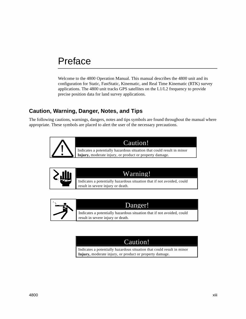
Caution, Warning, Danger, Notes, and TipsThe following cautions, warnings, dangers, notes and tips symbols are found throughout the manual where appropriate. These symbols are placed to alert the user of the necessary precautions.
Caution!Indicates a potentially hazardous situation that could result in minorInjury, moderate injury, or product or property damage.!
Warning!Indicates a potentially hazardous situation that if not avoided, couldresult in severe injury or death.
Danger!Indicates a potentially hazardous situation that if not avoided, couldresult in severe injury or death.
Caution!Indicates a potentially hazardous situation that could result in minorInjury, moderate injury, or product or property damage.
xiv 4800
Preface
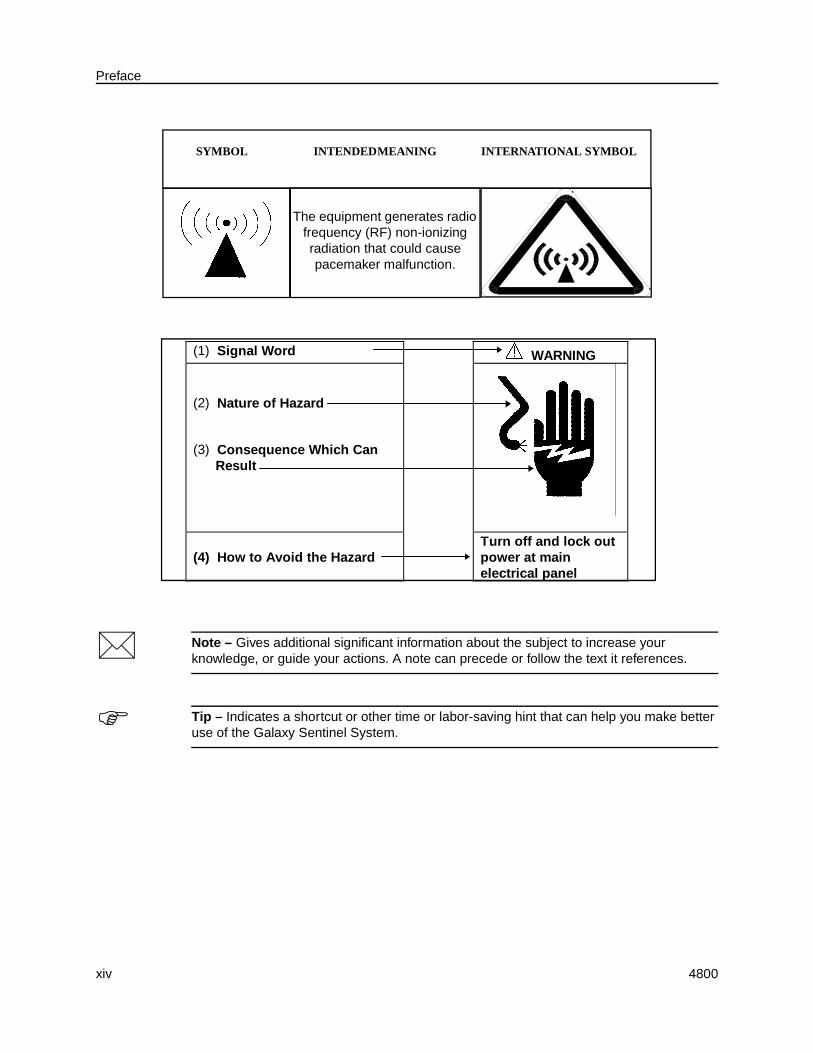
* Note – Gives additional significant information about the subject to increase your knowledge, or guide your actions. A note can precede or follow the text it references.
F Tip – Indicates a shortcut or other time or labor-saving hint that can help you make better use of the Galaxy Sentinel System.
SYMBOL INTENDED MEANING INTERNATIONAL SYMBOL
The equipment generates radio frequency (RF) non-ionizing radiation that could cause pacemaker malfunction.
(1) Signal Word WARNING
(2) Nature of Hazard
(3) Consequence Which CanResult
(4) How to Avoid the HazardTurn off and lock outpower at mainelectrical panel
4800 xv
Preface
Scope and AudienceThe following sections provide a guide to this manual and other documentation received with this product.
OrganizationThis manual contains the following chapters and appendices:
• Chapter 1, GPS Surveying Concepts, provides an overview of the GPS surveying topics as related to the 4800 unit.
• Chapter 2, Theory of Operation – Describes the block-diagram level theory of operation and provides general operation procedures.
• Chapter 3, Interfacing – Describes the 4800 interfacing connections, cable requirements, and related data.
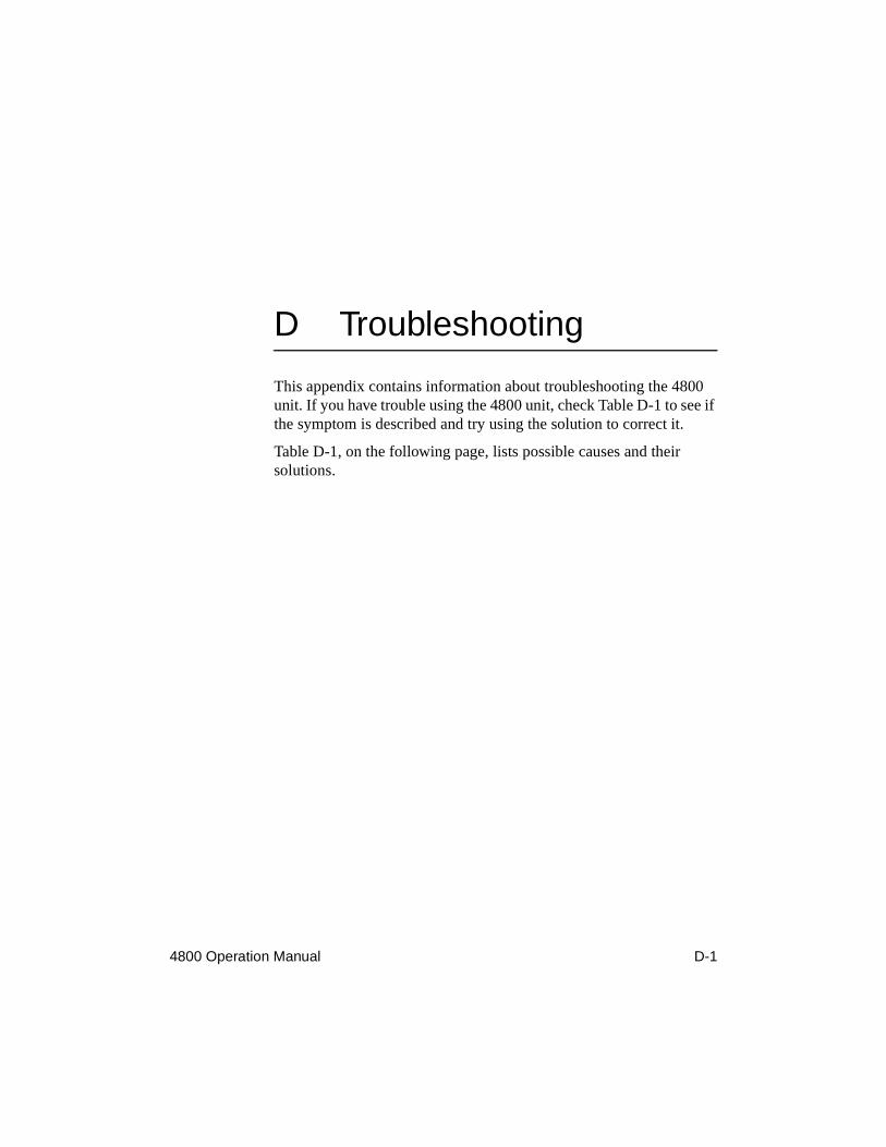
• Chapter 4, Troubleshooting – Provides data and procedures for localizing a problem to a replaceable assembly.
• Chapter 5, CU Service and Repair – Provides detailed instructions for disassembly and reassembly of the communications unit.
• Chapter 6, Service Operations – Provides procedures for updating Galaxy Sentinel memory and transferring files to and from disk.
• Appendix A, Parts and Release Information – Lists replaceable parts, field service kit(s), and software release history.
• Appendix B, Module Exchange Procedures – Describes standard warranty and non-warranty repair process.
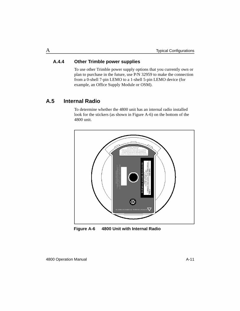
• Appendix C, typical Configuration of a 4800.
• Appendix D, describes the physical and technical specifications of the 4800.
• Appendix E, describes the NEMA-0183 output messages available from the 4800.
xvi 4800
Preface
Related Information
Related Manuals
"GPS, A Guide to the Next Utility", (P/N 16778) available from Trimble Navigation.
Where appropriate, this manual refers you to the other manuals for specific information.
Update Notes
A Warranty Activation Sheet is provided with your 4800 unit. When sending in your Warranty Activation Sheet, updated notes will be sent as they become available. These notes contain important information about software and hardware changes. Contact the local Trimble Dealer for more information about the support agreement contacts for software, firmware and extended warranty programs for hardware.
Technical Assistance
If you have problems and cannot find the information you need in this document, contact your local dealer.
If you need further assistance, contact the Trimble Technical Assistance Center (TAC) by phone, fax, or email. A support technician can help determine the cause of the problem and provide technical assistance. You can reach the TAC by any of the following means:
Sunnyvale TAC
Phone: +1-800-SOS-4TAC (North America)(+1-800-767-4822)+1-408-481-6940 (International)
Standard hours: 1400-0130 (UTC)(0600-1730 (Pacific Time))
Trimble UK TAC
Phone: +44-1256-746207
Fax: +44-1256-746299
Inmarsat Mobile #: 581-492340278 (AOR-E)
Standard hours: 0830-1730 (GMT), Monday – Friday
4800 xvii
Preface
When you contact TAC, have the following information available:
1. Trimble product name, any software or firmware version numbers, and if appropriate the serial number.
2. Your specific question or problem.
Please give detail background information such as the configuration of your data collector or receiver, and the exact type, make and configuration of your computer. If you have received an error message, please specify the exact wording.
If you need to send a data file along with your inquiry, please compress the file using PKZIP software by PKWARE, Inc., and name the file with the extension.zip.
Use one of the following methods to send the file;
• Attach the file to your email inquiry.
• Put the file on the Trimble BBS or the Trimble FTP site and include the filename in your email inquiry.
Worldwide Web
Check the Trimble worldwide web site and FTP site on the Internet for the latest news on new products and firmware, software, and document releases relevant to the Galaxy Sentinel product line.
Web site: http://www.trimble.com
FTP site: ftp://ftp.trimble.com/pub
The FTP site can also be access from the Trimble World Wide Web site. (http://www.trimble.com/support/support.htm)
Reader Comment FormA reader comment form is provided at the end of this guide. If this form is not available, you can send comments and suggestions to Trimble as follows:
• mail: Trimble Navigation Limited 645 North Mary Avenue, Post Office Box 3642 Sunnyvale, CA 94088-3642 USA
All comments and suggestions become the property of Trimble Navigation Limited.
xviii 4800
Preface
Document ConventionsItalics identify software menus, menu commands, dialog boxes, and the dialog box fields.
SMALL CAPITALS identify DOS commands, directories, filenames, and filename extensions.
Courier is used to represent what you see printed on the screen by the DOS system or program.
Courier Bold represents information that you must type in a software screen or window.
[Return] or [Ctrl] + [C] identifies a hardware function key or key combination that you must press on a PC.
Helvetica Bold represents a software command button.
4800 xix
Preface
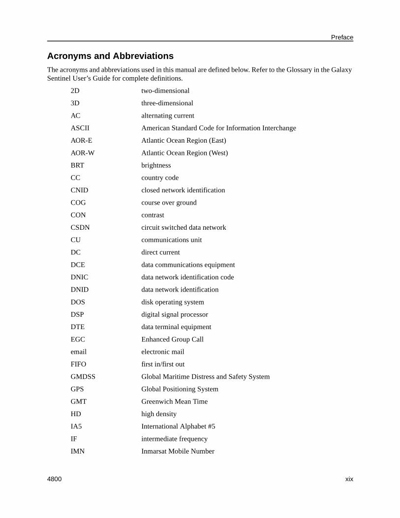
Acronyms and AbbreviationsThe acronyms and abbreviations used in this manual are defined below. Refer to the Glossary in the Galaxy Sentinel User’s Guide for complete definitions.
2D two-dimensional
3D three-dimensional
AC alternating current
ASCII American Standard Code for Information Interchange
AOR-E Atlantic Ocean Region (East)
AOR-W Atlantic Ocean Region (West)
BRT brightness
CC country code
CNID closed network identification
COG course over ground
CON contrast
CSDN circuit switched data network
CU communications unit
DC direct current
DCE data communications equipment
DNIC data network identification code
DNID data network identification
DOS disk operating system
DSP digital signal processor
DTE data terminal equipment
EGC Enhanced Group Call
email electronic mail
FIFO first in/first out
GMDSS Global Maritime Distress and Safety System
GPS Global Positioning System
GMT Greenwich Mean Time
HD high density
IA5 International Alphabet #5
IF intermediate frequency
IMN Inmarsat Mobile Number
xx 4800
Preface
IMO International Maritime Organization
Inmarsat International Maritime Satellite Organization
I/O input/output
IOR Indian Ocean Region
IP Information Provider
ITA-2 International Telex Alphabet #2
Lat latitude
LCD liquid crystal display
LED light emitting diode
LES land earth station
LESO LES Operator
Lon longitude
MMSI Maritime Mobile System Identification
MSI Maritime Safety Information
NAVAREA Navigation Area
NCS Network Coordination Station
NMEA National Maritime Electronics Association
PC personal computer
OR ocean region
POR Pacific Ocean Region
PSDN packet switched data network
PSTN public switched telephone network
RAP remote alarm panel
RCC Rescue Coordination Center
rcv receive
RF radio frequency
RO Routing Organization
Rx receive
SAR Search and Rescue
SCC Satellite Control Center
SES Ship Earth Station
SOG speed over ground
Tx transmit
4800 xxi
Preface
UTC Universal Time Coordinated
XMIT transmit
xxii 4800
Preface
4800 Operation Manual 1-1
1 GPS Surveying Concepts
This chapter provides an overview of GPS surveying topics and the GPSurvey™ software as related to the 4800 unit. For a more detailed explanation of GPS surveying, refer to the GPS Surveying General Reference in the GPSurvey Software documentation package.
GPS surveying requires the use of GPS receiver hardware, proper field procedures, and software. It is not necessary to have a thorough understanding of all of the principles of GPS to use it. However, it is useful to become familiar with the basic GPS terminology.
The Global Positioning System (GPS) is a satellite-based positioning system operated by the U.S. Department of Defense (DoD). This system provides all-weather, worldwide, 24-hour position and time information. The satellites broadcast signals that can be tracked by receivers for positioning and navigation purposes. The positioning accuracy of GPS ranges from 100 meters to less than 1 centimeter, depending upon the equipment and techniques used.
1-2 4800 Operation Manual
GPS Surveying Concepts 1
1.1 Number of Visible SatellitesThe Global Positioning System is designed so that at least four satellites are above the local horizon at all times. Normally, there are more than four satellites visible. Because the satellites are orbiting, satellite geometry changes throughout the day, but generally repeats from one day to the next. In general, track as many satellites as possible.
Low elevation satellites present problems for a GPS receiver. The amount of atmosphere that the GPS signals must travel through increases for low elevation satellites, and this adversely affects the GPS signal. These low elevation satellites have lower signal-to-noise ratios, and signal multipath tends to be worse.
1.2 Elevation MaskThe Elevation Mask is the cutoff angle for satellite tracking. The receiver ignores satellites below the Elevation Mask. The default Elevation Mask for the 4800 unit is 15°, which works well for most sites.
1.3 Logging RateThe default logging rate for the 4800 unit is 15 seconds. This is considered the optimal epoch interval for Static and FastStatic data collection. To increase precision, increase the observation period rather than reducing the logging rate.
4800 Operation Manual 1-3
1 GPS Surveying Concepts
1.4 Environmental FactorsEnvironmental factors that impact GPS measurement quality include:
• ionospheric activity
• tropospheric delay
• signal obstructions
• multipath
• radio interference
High ionospheric activity causes rapid changes in GPS signal delay, even between closely spaced receivers. Ionospheric activity is most extreme at the polar and equatorial regions, and it varies along an 11-year cycle. During periods of high ionospheric activity, real-time kinematic initialization performance can be degraded in the time-to-initialize and in precision of the results.
1.5 GPS versus Conventional Surveying TechniquesThe following are advantages of GPS over conventional surveying techniques:
• Line-of-sight between stations is not required.
• GPS accuracy is subject to little degradation by weather (rain, snow, high or low temperatures, or humidity).
• GPS is faster than conventional methods.
• GPS provides results in a unified world coordinate system.
• GPS results are digital and easily transferred to mapping or GIS systems.
There are many options for observing GPS baselines. For example, GPS surveys can be conducted either as postprocessed surveys or real-time kinematic (RTK) surveys.
1-4 4800 Operation Manual
GPS Surveying Concepts 1
1.5.1 Postprocessed Surveys
In the default configuration, the 4800 unit is designed for postprocessed surveys. In postprocessed surveys, data is logged in the receiver or in a handheld data collector, then downloaded at the office to a PC and processed using specially designed software, such as GPSurvey.
When data is collected for postprocessing, there are a number of different data collection techniques. The terms Static, FastStatic, and kinematic refer to different methods of collecting data in the field. Kinematic surveys can include both stop-and-go kinematic and continuous kinematic.
In general, unless a survey technique or piece of equipment states real-time or RTK, assume data is being logged for postprocessing.
1.5.2 Real-Time Kinematic Surveys
The 4800 unit can be configured with a real-time kinematic upgrade, which includes all the necessary hardware and software to support real-time surveying applications (for example, stakeout, monument recovery, and topo). In real-time kinematic surveys, data processing occurs in the field as data is logged, providing immediate results (coordinates) in the handheld data collector.
Real-time surveys are kinematic surveys with a communications link (radio) between the base receiver and rover. Like the postprocessed kinematic technique, RTK can include stop-and-go data collection and continuous data collection. Real-time surveys with the 4800 unit always require a TSC1 handheld unit at the rover station.
4800 Operation Manual 1-5
1 GPS Surveying Concepts
1.5.3 GPS Surveying Methods
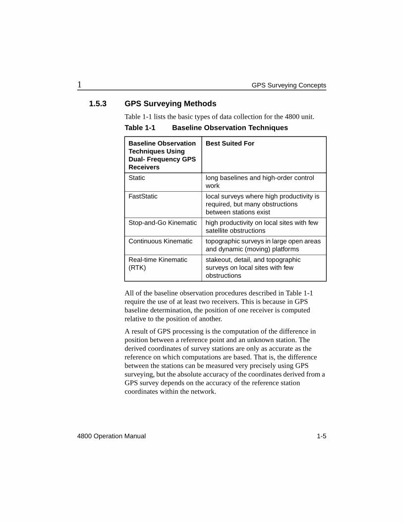
Table 1-1 lists the basic types of data collection for the 4800 unit.
All of the baseline observation procedures described in Table 1-1 require the use of at least two receivers. This is because in GPS baseline determination, the position of one receiver is computed relative to the position of another.
A result of GPS processing is the computation of the difference in position between a reference point and an unknown station. The derived coordinates of survey stations are only as accurate as the reference on which computations are based. That is, the difference between the stations can be measured very precisely using GPS surveying, but the absolute accuracy of the coordinates derived from a GPS survey depends on the accuracy of the reference station coordinates within the network.
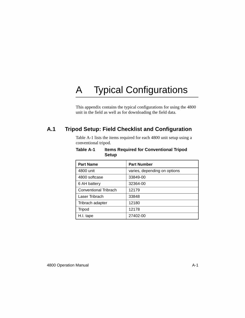
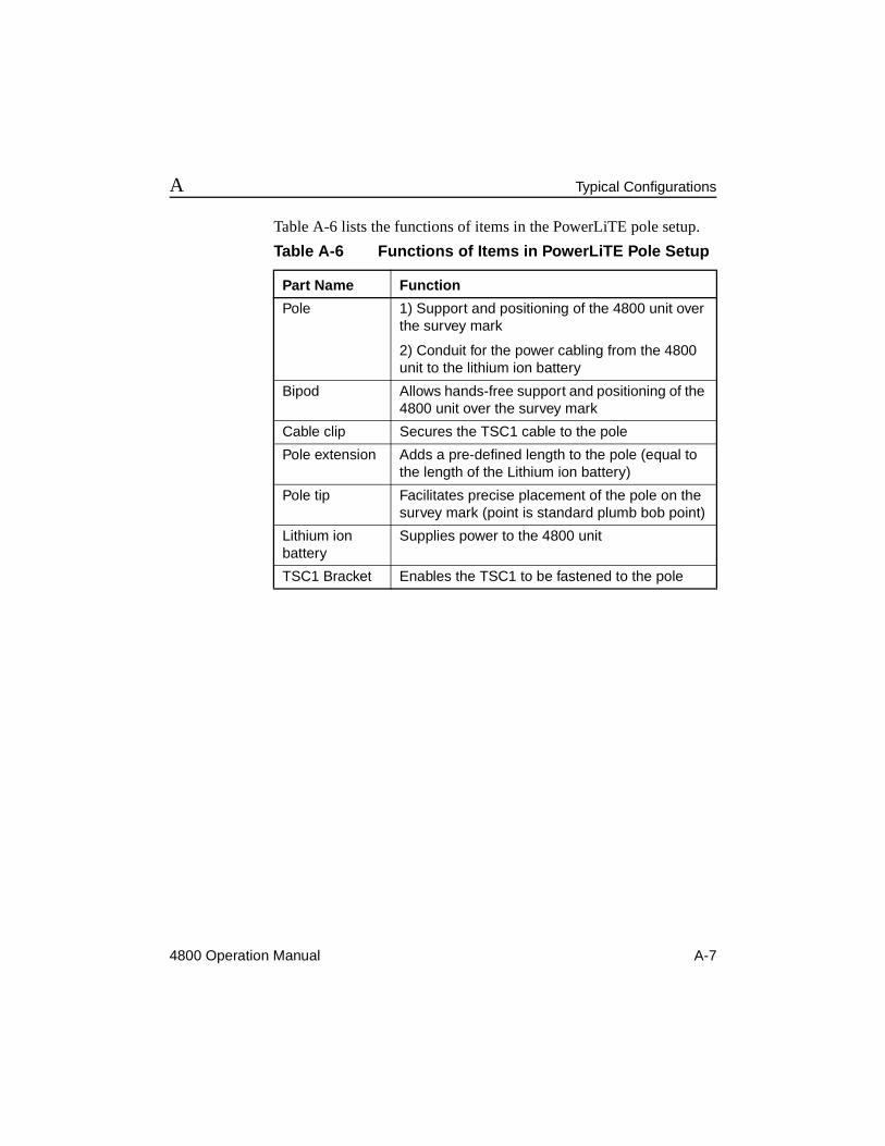
Table 1-1 Baseline Observation Techniques
Baseline Observation Techniques Using Dual- Frequency GPS Receivers
Best Suited For
Static long baselines and high-order control work
FastStatic local surveys where high productivity is required, but many obstructions between stations exist
Stop-and-Go Kinematic high productivity on local sites with few satellite obstructions
Continuous Kinematic topographic surveys in large open areas and dynamic (moving) platforms
Real-time Kinematic (RTK)
stakeout, detail, and topographic surveys on local sites with few obstructions
1-6 4800 Operation Manual
GPS Surveying Concepts 1
Each data collection method has special conditions associated with it that dictate how and when the method can be used. The following section describes types of GPS survey networks and the data collection methods you can employ with the 4800 unit.
4800 Operation Manual 1-7
1 GPS Surveying Concepts
1.6 Design of GPS SurveysBefore going out to the field to collect data, develop a scheme or design for what you want to measure. To do so, answer this question: what is the objective for this survey?
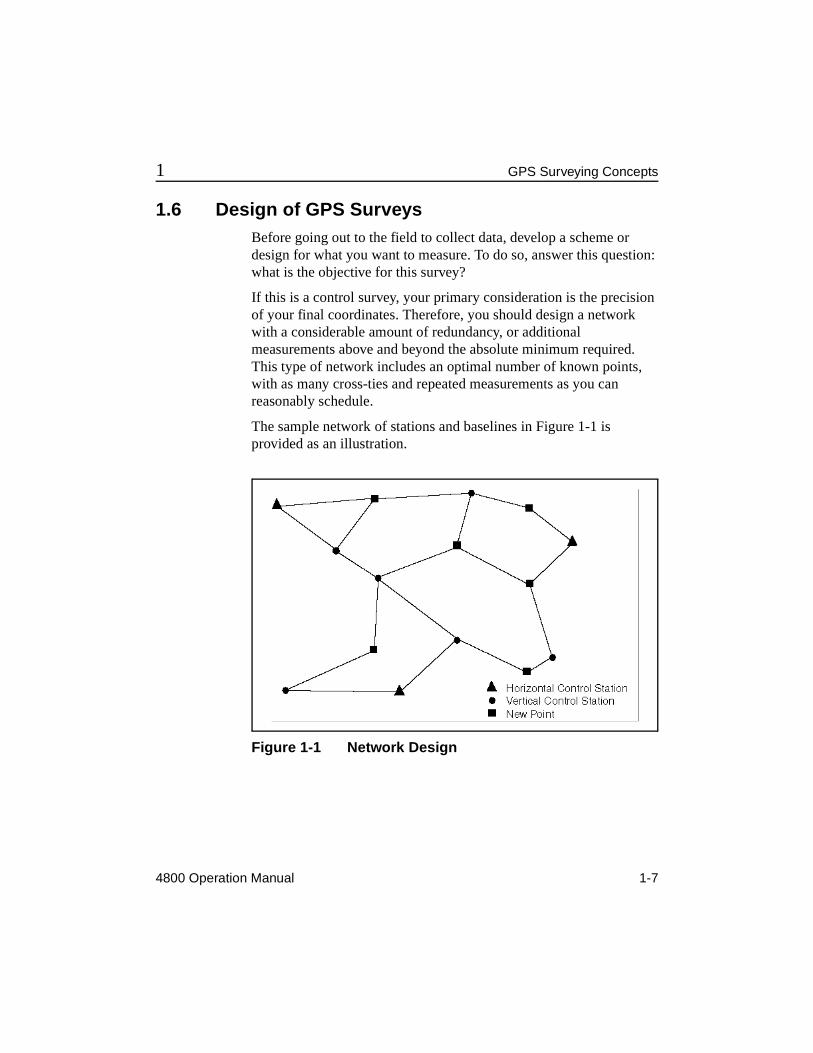
If this is a control survey, your primary consideration is the precision of your final coordinates. Therefore, you should design a network with a considerable amount of redundancy, or additional measurements above and beyond the absolute minimum required. This type of network includes an optimal number of known points, with as many cross-ties and repeated measurements as you can reasonably schedule.
The sample network of stations and baselines in Figure 1-1 is provided as an illustration.
Figure 1-1 Network Design
1-8 4800 Operation Manual
GPS Surveying Concepts 1
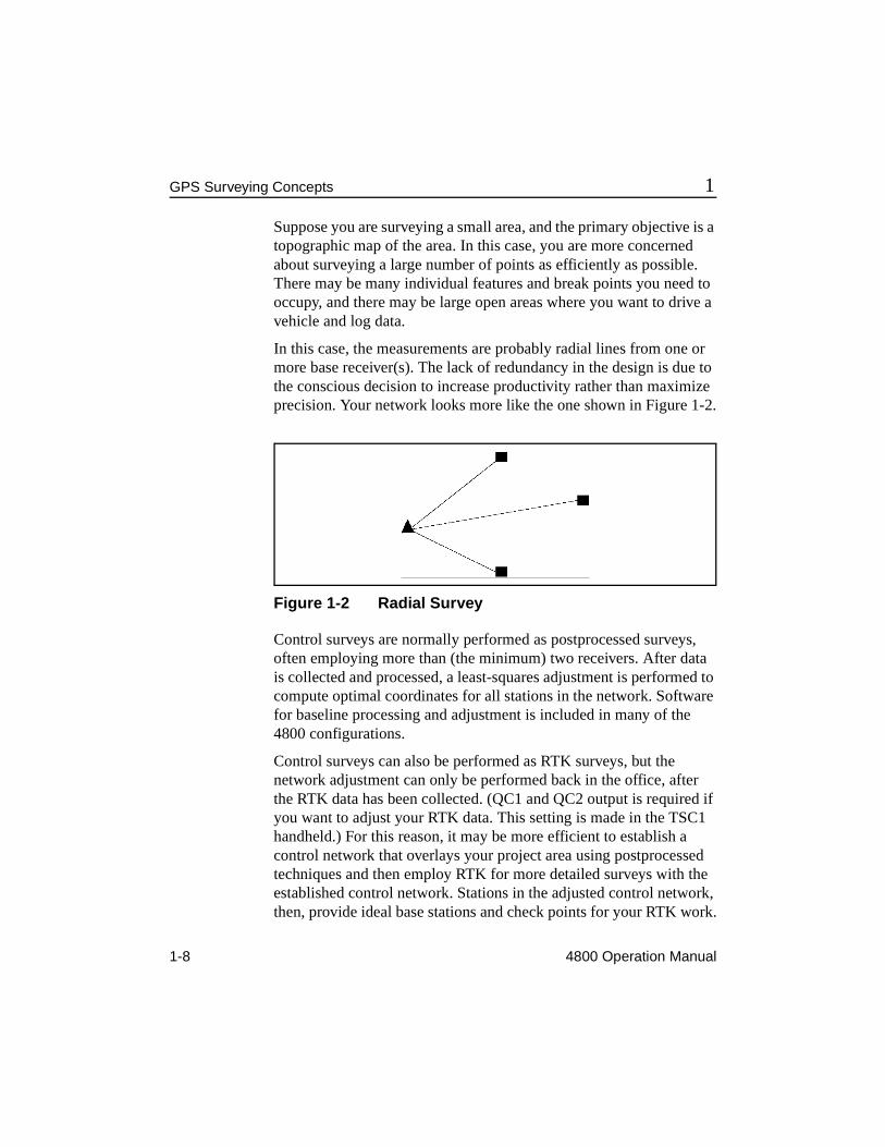
Suppose you are surveying a small area, and the primary objective is a topographic map of the area. In this case, you are more concerned about surveying a large number of points as efficiently as possible. There may be many individual features and break points you need to occupy, and there may be large open areas where you want to drive a vehicle and log data.
In this case, the measurements are probably radial lines from one or more base receiver(s). The lack of redundancy in the design is due to the conscious decision to increase productivity rather than maximize precision. Your network looks more like the one shown in Figure 1-2.
Figure 1-2 Radial Survey
Control surveys are normally performed as postprocessed surveys, often employing more than (the minimum) two receivers. After data is collected and processed, a least-squares adjustment is performed to compute optimal coordinates for all stations in the network. Software for baseline processing and adjustment is included in many of the 4800 configurations.
Control surveys can also be performed as RTK surveys, but the network adjustment can only be performed back in the office, after the RTK data has been collected. (QC1 and QC2 output is required if you want to adjust your RTK data. This setting is made in the TSC1 handheld.) For this reason, it may be more efficient to establish a control network that overlays your project area using postprocessed techniques and then employ RTK for more detailed surveys with the established control network. Stations in the adjusted control network, then, provide ideal base stations and check points for your RTK work.
4800 Operation Manual 1-9
1 GPS Surveying Concepts
After you have decided what it is you want to survey, you can start planning how you want to execute the survey and determine the optimal method of collecting the data. The next section describes the options for data collection with the 4800 unit.
* Note – In this manual the reference, base or base station refers to the 4800 unit positioned over a known point. The 4800 unit measuring an unknown point is called the rover.
1.7 Postprocessed SurveyingThe 4800 unit can be used in Static, FastStatic, as well as RTK and postprocessed kinematic surveys. You can use the 4800 unit with any other Trimble survey grade receivers for this purpose.
The following items are important conditions for this application:
• At least one other receiver must log data at the same epoch rate and at the same time to be able to compute baselines.
• For every baseline desired, each receiver on the points defining the desired baseline must be tracking at least four satellites in common.
• Each receiver must be a survey-grade receiver, capable of logging both C/A code and at least L1 carrier phase observables.
• The 4800 unit is a dual-frequency receiver—to achieve dual-frequency baseline results, the unit must be used with another dual-frequency receiver.
Static and FastStatic are two types of postprocessed surveys.
1-10 4800 Operation Manual
GPS Surveying Concepts 1
1.7.1 Static Surveying
Static surveying is the most precise GPS surveying technique, but requires long occupation times at each station. Like all GPS surveys, the Static survey requires the use of at least two units, at either end of a baseline, logging observations simultaneously from at least four common satellites. Static surveying requires that observations be logged for an extended period of time, usually about 45 to 60 minutes.
Although Static surveying requires more time than other techniques, it is also more forgiving. A large amount of data are collected during this 45-60 minute period, and this enables the processing software to resolve more problems in the data set than might otherwise be resolved in shorter observation periods. Furthermore, the additional data typically lead to greater precision in the baseline solution.
The information associated with a Static occupation is stored in a separate, unique data file. There is only one occupation per file. If for any reason the unit is turned off in the middle of an occupation, a second file can be opened and the survey can continue. In this case, there is more than one file per occupation, but still only one occupation per file. The GPSurvey software (the baseline processing software) offers an option to concatenate (combine) these files when downloading.
Static surveys can be performed with either single-frequency or dual-frequency receivers. The 4800 unit is an integrated dual-frequency receiver and antenna.
The occupation time required for a Static survey depends on many factors. Trimble recommends an occupation time of at least 45 minutes when five or more satellites are available, or 60 minutes during times when only four satellites are available. The GPSurvey software allows two planning modes: Plan and Quick Plan. Either of these (essentially identical utilities) can help you determine satellite availability at a specified site and time.
4800 Operation Manual 1-11
1 GPS Surveying Concepts
Static surveying techniques are generally used for projects where the highest precision is required. At least two receivers are required, but you can use multiple receivers to increase productivity. The sequence of observations should be dictated by your network design. Remember the most important rule of surveying with GPS: only common data between receivers can be processed, therefore you must be sure to have your receivers logging data at the same epoch rate, at the same time of day, and observing the same satellites.
1.7.2 FastStatic Surveying
FastStatic surveying is a data collection technique that is similar to Static surveying in some ways and similar to kinematic surveying in other ways.
FastStatic versus Static
FastStatic surveying requires at least two receivers logging common data from two different locations. The length of time the receivers log data depends on the number of satellites being tracked, the geometry of the satellites being tracked (PDOP), and the quality of the data being logged.
Items affecting the quality of data are cycle slips (interruptions of data logging on one or more satellites), multipath (reflections of the satellite signal off nearby surfaces, such as the roof of a car), and radio frequency (RF) interference.
In general, occupation times for FastStatic surveys on baselines ≤ 20km range from about 8 minutes with at least 6 satellites to about 20 minutes with 4 satellites.
FastStatic surveying is similar to Static surveying in that data is logged only while the receiver is stationary and occupying a point. As the receiver moves from each point to another point in the survey, no data is logged, since the 4800 unit is turned off. The manner in which the data is treated by the baseline processor is also similar.
1-12 4800 Operation Manual
GPS Surveying Concepts 1
FastStatic surveying differs from Static surveying in the fact that less data is collected. The occupation time is shorter, resulting in fewer measurements for the baseline processor to use. Therefore, the expected baseline precision is not quite as high for FastStatic as it is for Static.
FastStatic using a TSC1 Handheld
A less important distinction between FastStatic and Static is the potential for logging more than one occupation within a single data file. The 4800 unit requires the use of a TSC1™ handheld data collector to perform a FastStatic survey with multiple occupations in a single data file. In this application, the data file remains open while the receiver moves between occupations, but no data is logged. The advantage in this case is efficiency in the field. If you do not have a TSC1 handheld, then each of your FastStatic occupations are logged in the 4800 unit as individual, unique data files with one occupation per file.
Refer to Survey Controller Reference Manual and Survey Controller Field Guide for more information on TSC1 handheld operation.
FastStatic versus Kinematic
FastStatic surveying also shares similarities with kinematic surveying. Because FastStatic procedures are highly productive, they are often used in the same type of network design as kinematic techniques. This design calls for at least one base receiver, which logs data constantly throughout the survey, and one or more roving receivers, which move from point to point, logging data at each stationary occupation. The result is a radial survey from each base receiver.
There is no requirement to restrict FastStatic techniques to a radial survey. The application of a particular data collection technique to a particular network design is a decision left to the individual surveyor.
4800 Operation Manual 1-13
1 GPS Surveying Concepts
When logging data in a FastStatic survey, it is very important to obtain the best data possible. Because the occupation times are relatively short, the PDOP should be low and conditions for multipath minimized. It is also very important to log data that is free of cycle slips, so obstructions to the sky at each station should be minimized. If obstructions exist at stations, use the PLAN (or Quick Plan) module to help account for the obstructions and optimize field observation time.
If you are planning to set up one receiver as a base receiver for a significant portion of your survey, select a site that has a clear a view of the sky. With the roving receiver, track the required number of satellites continuously for the minimum time specified. The 4800 unit informs you when sufficient data has been collected with a slow flashing Data LED (yellow).
1.8 Sample Field Survey - PostprocessedFor this example, consider a survey for an area that is about 800 meters, or about 2500 feet, on each side. In this survey, you have recovered monuments at all four corners, and you are expected to measure between these monuments. FastStatic techniques will be used to measure the baselines between monuments.
In this example, we assume you have three 4800 units to perform the field work.
1-14 4800 Operation Manual
GPS Surveying Concepts 1
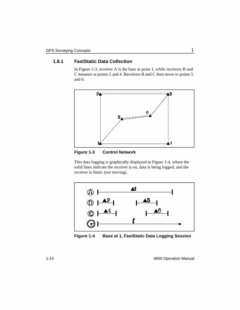
1.8.1 FastStatic Data Collection
In Figure 1-3, receiver A is the base at point 1, while receivers B and C measure at points 2 and 4. Receivers B and C then move to points 5 and 6.
Figure 1-3 Control Network
This data logging is graphically displayed in Figure 1-4, where the solid lines indicate the receiver is on, data is being logged, and the receiver is Static (not moving).
Figure 1-4 Base at 1, FastStatic Data Logging Session
4800 Operation Manual 1-15
1 GPS Surveying Concepts
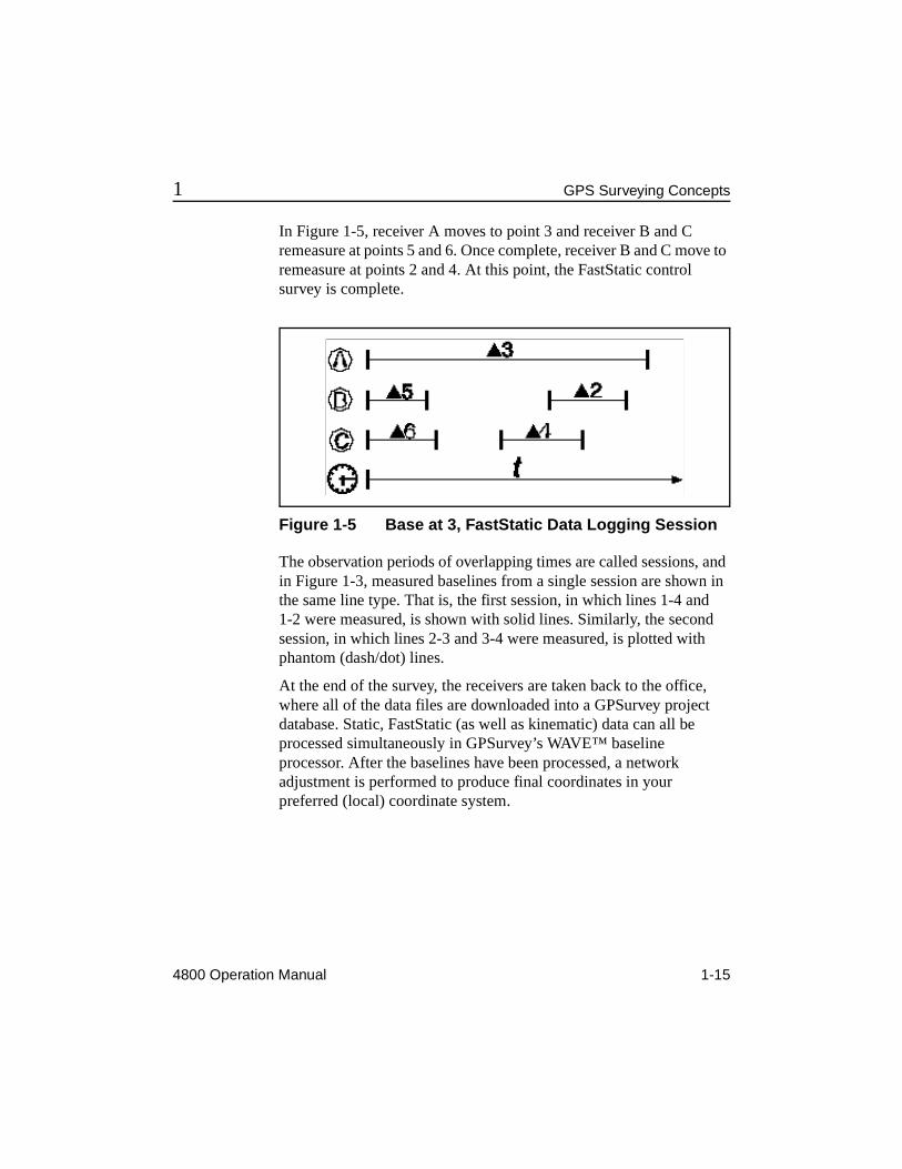
In Figure 1-5, receiver A moves to point 3 and receiver B and C remeasure at points 5 and 6. Once complete, receiver B and C move to remeasure at points 2 and 4. At this point, the FastStatic control survey is complete.
Figure 1-5 Base at 3, FastStatic Data Logging Session
The observation periods of overlapping times are called sessions, and in Figure 1-3, measured baselines from a single session are shown in the same line type. That is, the first session, in which lines 1-4 and 1-2 were measured, is shown with solid lines. Similarly, the second session, in which lines 2-3 and 3-4 were measured, is plotted with phantom (dash/dot) lines.
At the end of the survey, the receivers are taken back to the office, where all of the data files are downloaded into a GPSurvey project database. Static, FastStatic (as well as kinematic) data can all be processed simultaneously in GPSurvey’s WAVE™ baseline processor. After the baselines have been processed, a network adjustment is performed to produce final coordinates in your preferred (local) coordinate system.
1-16 4800 Operation Manual
GPS Surveying Concepts 1
4800 Operation Manual 2-1
2 General Operation
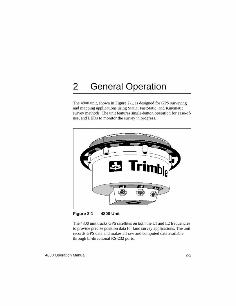
The 4800 unit, shown in Figure 2-1, is designed for GPS surveying and mapping applications using Static, FastStatic, and Kinematic survey methods. The unit features single-button operation for ease-of-use, and LEDs to monitor the survey in progress.
Figure 2-1 4800 Unit
The 4800 unit tracks GPS satellites on both the L1 and L2 frequencies to provide precise position data for land survey applications. The unit records GPS data and makes all raw and computed data available through bi-directional RS-232 ports.
2-2 4800 Operation Manual
General Operation 2
2.1 ApplicationsThe 4800 unit is designed to excel in surveying applications. It can perform Static, FastStatic, and Kinematic surveys. Survey data is logged internally for later downloading to a computer.
Trimble’s GPSurvey software program postprocesses logged data for various types of applications.
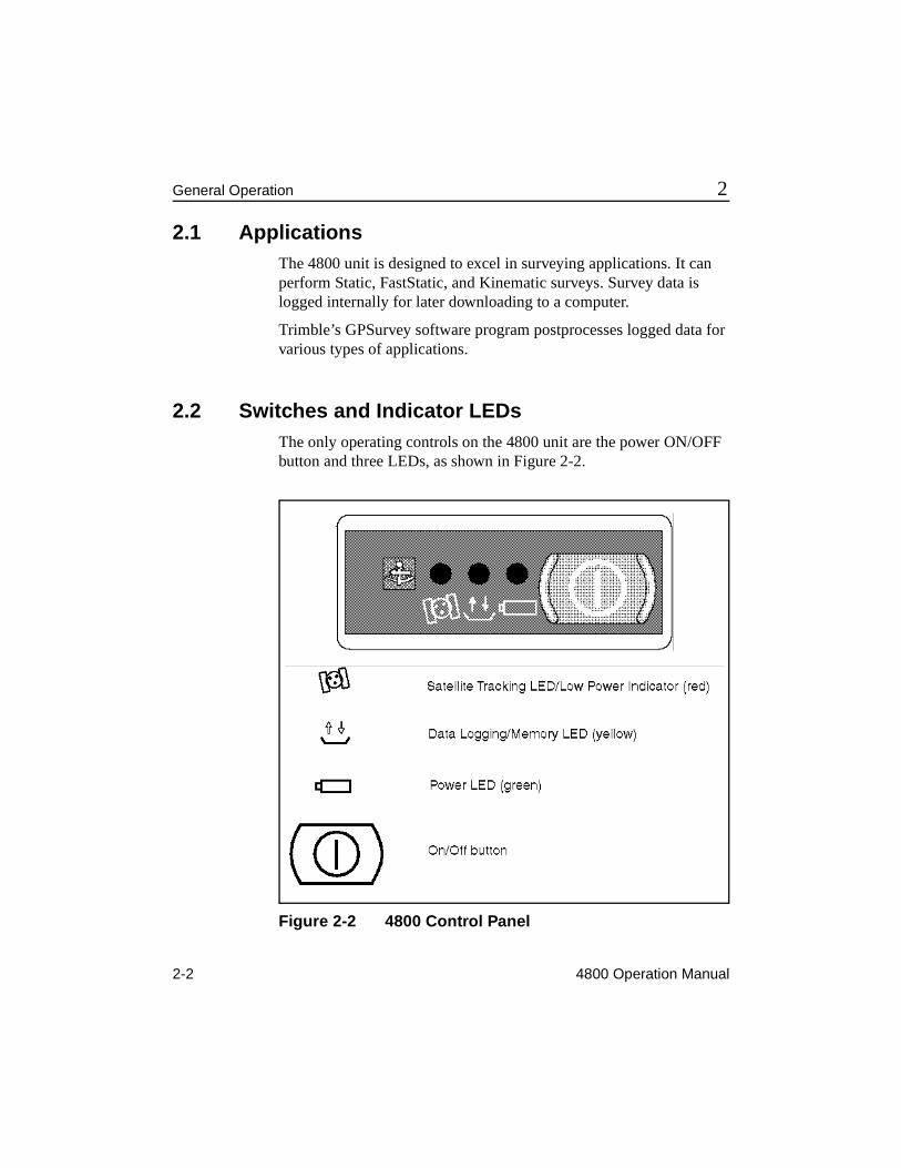
2.2 Switches and Indicator LEDsThe only operating controls on the 4800 unit are the power ON/OFF button and three LEDs, as shown in Figure 2-2.
Figure 2-2 4800 Control Panel
4800 Operation Manual 2-3
2 General Operation
During typical operation, slow-blinking LEDs indicate normal operation. Fast-blinking LEDs indicate a condition that may have a negative effect on the survey and may require operator attention. A solid red LED indicates low battery power. LEDs that are off indicate that no operation is occurring.
During normal operation, the 4800 unit transitions through three stages:
1. Power Up and Initialization
When you press the power button to turn the 4800 unit on, the green LED remains on solid and the other LEDs turn off. The red satellite tracking LED starts blinking fast while the receiver locks onto the first 3 satellites. As soon as it locks onto 4 or more satellites, the red tracking LED begins to blink slowly. When this happens, a data file is opened and the yellow data logging LED turns on solid.
2. Data Logging/Memory
When the 4800 unit is logging data normally, the red LED blinks slowly and the yellow LED is on solid. During this period data is stored, the unit is tracking satellites, and the internal processor is timing how long it needs to log data for a FastStatic survey.
3. When the 4800 unit determines that enough data has been logged for the FastStatic survey (see Section 4.3.3, Minimum Observation Times for details), the yellow data LED blinks slowly. At this time it is safe to turn the unit off if the baseline being measured is within the FastStatic limits. If the unit is left on, it continues to log data, provided adequate memory and power are available.
2-4 4800 Operation Manual
General Operation 2
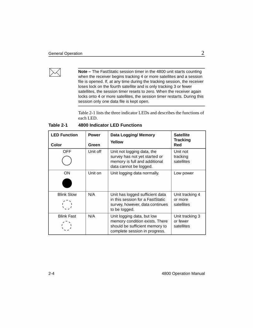
* Note – The FastStatic session timer in the 4800 unit starts counting when the receiver begins tracking 4 or more satellites and a session file is opened. If, at any time during the tracking session, the receiver loses lock on the fourth satellite and is only tracking 3 or fewer satellites, the session timer resets to zero. When the receiver again locks onto 4 or more satellites, the session timer restarts. During this session only one data file is kept open.
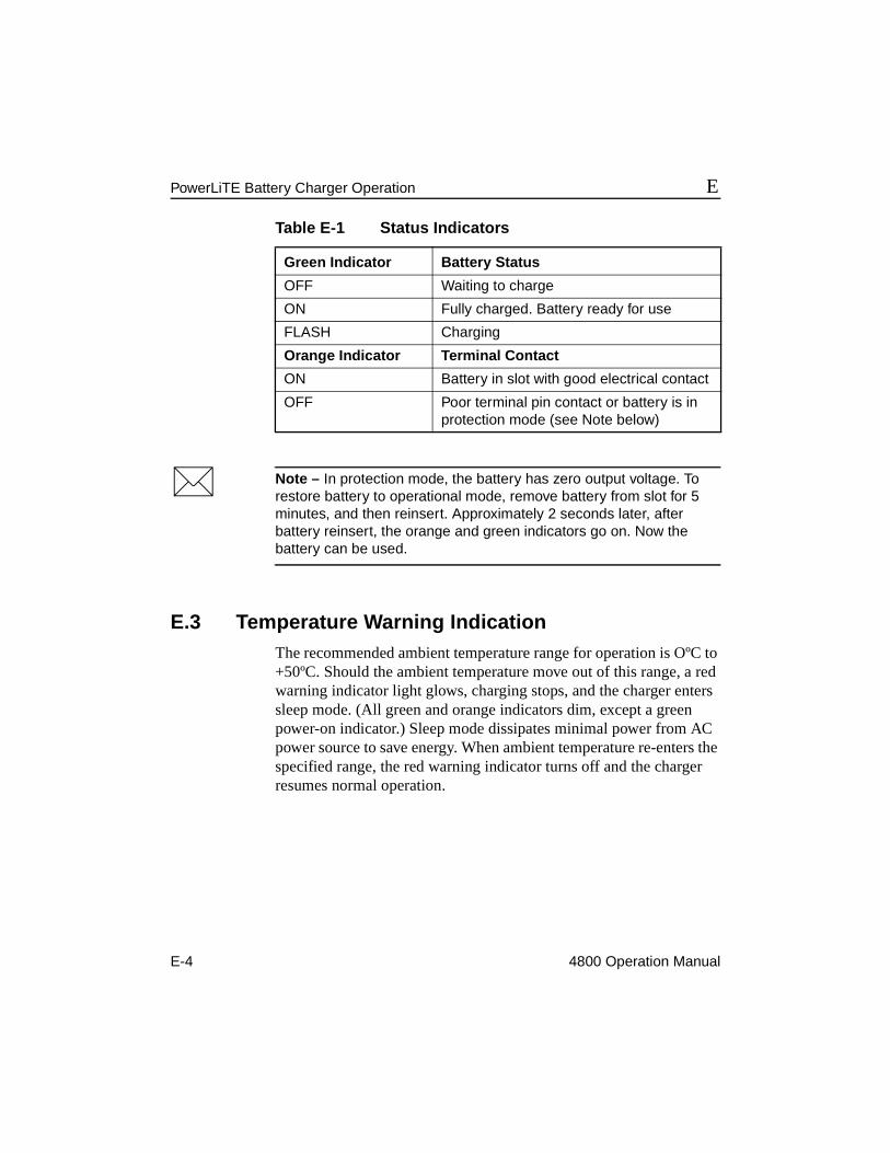
Table 2-1 lists the three indicator LEDs and describes the functions of each LED.
Table 2-1 4800 Indicator LED Functions
LED Function
Color
Power
Green
Data Logging/ Memory
Yellow
Satellite TrackingRed
OFF Unit off Unit not logging data, the survey has not yet started or memory is full and additional data cannot be logged.
Unit not tracking satellites
ON Unit on Unit logging data normally. Low power
Blink Slow N/A Unit has logged sufficient data in this session for a FastStatic survey, however, data continues to be logged.
Unit tracking 4 or more satellites
Blink Fast N/A Unit logging data, but low memory condition exists. There should be sufficient memory to complete session in progress.
Unit tracking 3 or fewer satellites
4800 Operation Manual 2-5
2 General Operation
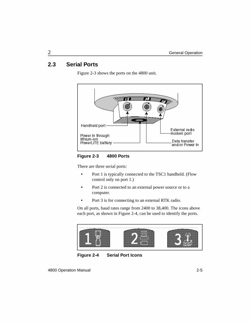
2.3 Serial PortsFigure 2-3 shows the ports on the 4800 unit.
Figure 2-3 4800 Ports
There are three serial ports:
• Port 1 is typically connected to the TSC1 handheld. (Flow control only on port 1.)
• Port 2 is connected to an external power source or to a computer.
• Port 3 is for connecting to an external RTK radio.
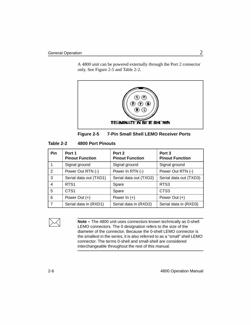
On all ports, baud rates range from 2400 to 38,400. The icons above each port, as shown in Figure 2-4, can be used to identify the ports.
Figure 2-4 Serial Port Icons
2-6 4800 Operation Manual
General Operation 2
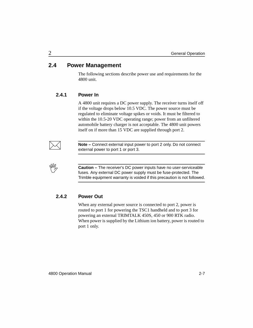
A 4800 unit can be powered externally through the Port 2 connector only. See Figure 2-5 and Table 2-2.
Figure 2-5 7-Pin Small Shell LEMO Receiver Ports
* Note – The 4800 unit uses connectors known technically as 0-shell LEMO connectors. The 0 designation refers to the size of the diameter of the connector. Because the 0-shell LEMO connector is the smallest in the series, it is also referred to as a “small” shell LEMO connector. The terms 0-shell and small-shell are considered interchangeable throughout the rest of this manual.
Table 2-2 4800 Port Pinouts
Pin Port 1Pinout Function
Port 2Pinout Function
Port 3Pinout Function
1 Signal ground Signal ground Signal ground
2 Power Out RTN (-) Power In RTN (-) Power Out RTN (-)
3 Serial data out (TXD1) Serial data out (TXD2) Serial data out (TXD3)
4 RTS1 Spare RTS3
5 CTS1 Spare CTS3
6 Power Out (+) Power In (+) Power Out (+)
7 Serial data in (RXD1) Serial data in (RXD2) Serial data in (RXD3)
4800 Operation Manual 2-7
2 General Operation
2.4 Power ManagementThe following sections describe power use and requirements for the 4800 unit.
2.4.1 Power In
A 4800 unit requires a DC power supply. The receiver turns itself off if the voltage drops below 10.5 VDC. The power source must be regulated to eliminate voltage spikes or voids. It must be filtered to within the 10.5-20 VDC operating range; power from an unfiltered automobile battery charger is not acceptable. The 4800 unit powers itself on if more than 15 VDC are supplied through port 2.
* Note – Connect external input power to port 2 only. Do not connect external power to port 1 or port 3.
I Caution – The receiver's DC power inputs have no user-serviceable fuses. Any external DC power supply must be fuse-protected. The Trimble equipment warranty is voided if this precaution is not followed.
2.4.2 Power Out
When any external power source is connected to port 2, power is routed to port 1 for powering the TSC1 handheld and to port 3 for powering an external TRIMTALK 450S, 450 or 900 RTK radio. When power is supplied by the Lithium ion battery, power is routed to port 1 only.
2-8 4800 Operation Manual
General Operation 2
2.4.3 External Power Sources
The 4800 unit requires an external power source. The typical configurations are as follows:
• The 6AH battery is standard for Static and FastStatic applications.
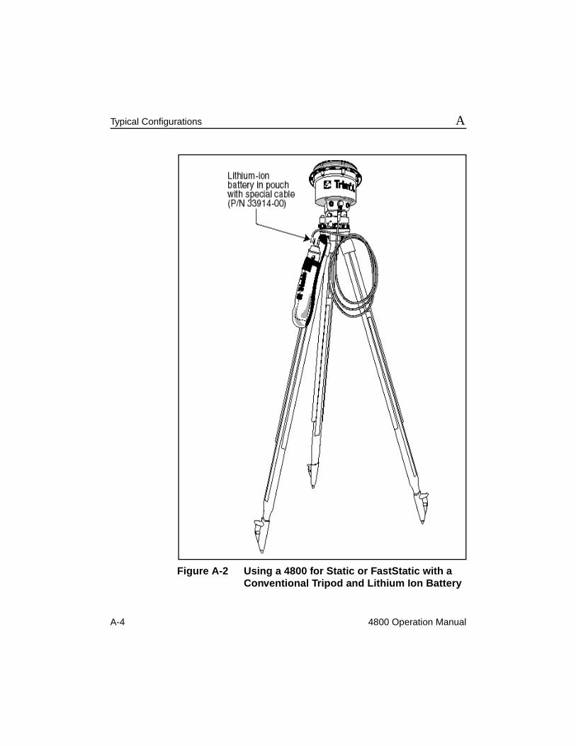
• The Lithium ion battery (P/N 31030-00, part of the PowerLiTE™ rangepole assembly) is standard for roving applications (for example, postprocessed and real-time kinematic).
Refer to Appendix A, Typical Configurations for diagrams of configurations.
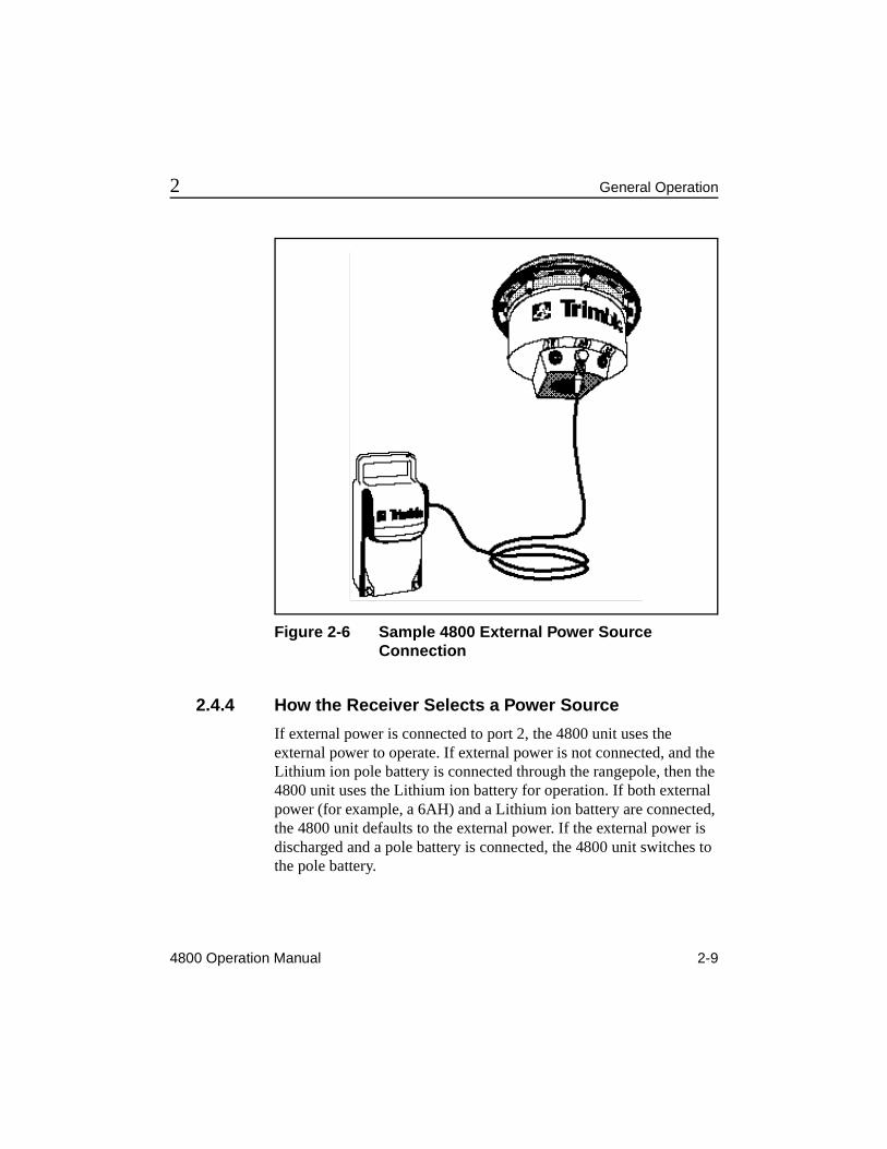
The 4800 unit is designed to operate using an external power source, as shown in Figure 2-6. External power is connected to the unit at port 2 using a 0-shell LEMO 7-pin connector. Any external power source must provide 10.5 to 20 VDC for the unit to operate properly. Trimble recommends using the 6AH battery (P/N 32364-00) or equivalent.
I Caution – When the temperature falls below 10°F (-12°C) the PowerLiTE battery should not be used in Port 2. Port 2’s shutdown cutoff is set at 10.5VDC in order to avoid permanent damage to a lead acid battery.
M Warning – Do not apply more than 20 VDC to the 4800 unit.
* Note – When both Lithium ion (pole) batteries and external batteries are connected, the 4800 unit uses the external source first.
4800 Operation Manual 2-9
2 General Operation
Figure 2-6 Sample 4800 External Power Source Connection
2.4.4 How the Receiver Selects a Power Source
If external power is connected to port 2, the 4800 unit uses the external power to operate. If external power is not connected, and the Lithium ion pole battery is connected through the rangepole, then the 4800 unit uses the Lithium ion battery for operation. If both external power (for example, a 6AH) and a Lithium ion battery are connected, the 4800 unit defaults to the external power. If the external power is discharged and a pole battery is connected, the 4800 unit switches to the pole battery.
2-10 4800 Operation Manual
General Operation 2
2.4.5 Restarting the Survey After Power-Down
When the 4800 unit is powered on, and auto data logging starts, the survey parameters (elevation mask, epoch interval, and so on) are set to the default values. However, if one of the following things occurs during the survey:
• a power failure
• an automatic power-down due to low battery
• the surveyor powers down before changing the battery after the “low battery warning” (solid red LED) has occurred
then the survey parameters are maintained from the previous session when the unit automatically restarts after power-up.
For example, in this case, the 4800 unit is powered up and started with the TSC1 handheld, and the epoch interval is changed to 5 seconds (postprocessed kinematic survey). If the power supply to the 4800 unit is disconnected during the survey, such as by pulling the battery cable from port #2 (power failure) and the unit is restarted, it maintains the previously set 5-second epoch interval. The same happens during an automatic power-down due to a low battery or a power-down before changing the battery after the “low battery warning” (solid red LED) has occurred.
However, if the 4800 unit is manually powered down (with the power key) before the low power warning, and then restarted, it sets default parameters and resets the epoch interval to 15 seconds.
To summarize, if the 4800 unit is powered off normally, the settings are returned to the defaults; if an abnormal power-off condition occurs, the current settings are retained.
4800 Operation Manual 2-11
2 General Operation
2.4.6 Charging the Batteries
The typical configurations for charging the batteries used with a 4800 unit are:
• 6AH charger for the 6AH battery (P/N 34106-00, battery kit including battery, charger and powercord)
• 4-barrel charger for the Lithium-ion batteries (P/N 34108-00, PowerLiTE charger kit). See Appendix E for details.
2.5 Clearing RAM and File SystemIf the power key is held down continuously at power-up, the following sequence occurs:
1. After 15 seconds the GPS red LED turns on and a RAM clear (SV almanacs and ephemerides are cleared; all control parameters reset to default) is triggered to occur when the unit next powers up.
2. After 60 seconds any survey datalogging in progress is terminated and the file system is fully initialized (all files are deleted). The receiver then powers down.
At any time between 15 and 60 seconds (while the LED is on), the power key can be released. This powers down the unit, leaving the file system unchanged.
M Warning – Clearing the file system (60-second key press) deletes all data files in the 4800 unit, including files that may not have been downloaded.
2-12 4800 Operation Manual
General Operation 2
2.6 Use and CareThe 4800 unit is designed to tolerate the sort of rough treatment that equipment may suffer in the field. Nevertheless, it is a high-precision electronic instrument and should be treated with reasonable care.
The unit operates in temperatures from -40° to +55° Celsius (-40°F to +131°F).
The receiver is protected with both internal and external bumpers for vibration and shock mitigation. The receiver is designed and has been tested to withstand an accidental drop when mounted to a 1.8 meter long pole (PowerLiTE Pole). A drop of this magnitude could scratch or slightly deform the external bumper ring. This will not affect the GPS performance of the receiver.
High-power signals from a nearby radio or radar transmitter can overwhelm the unit's receiver circuits. This does not harm the unit, but can prevent it from functioning. To avoid problems, try not to use the 4800 unit within 400 meters of powerful radar, television, or other transmitters. Low-power transmitters such as the ones in portable phones and walkie-talkies, and transmission lines normally do not interfere with unit operations. For more information, see the Trimble technical note Using Radio Communication Systems with GPS Surveying Receivers.
2.7 COCOM LimitsThe U.S. Department of Commerce requires that all exportable GPS products contain performance limitations so that they cannot be used in a manner that could threaten the security of the United States. The following limitations are implemented on the 4800 unit.
Immediate access to satellite measurements and navigation results is disabled when the receiver's velocity is computed to be greater than 1000 knots, or its altitude is computed to be above 18,000 meters. The unit continuously resets until the COCOM situation is cleared.
4800 Operation Manual 2-13
2 General Operation
2.8 Data ManagementThe 4800 unit automatically assigns a filename and creates a tracking session file when the unit begins tracking four or more satellites after start-up. Each filename identifies the specific receiver by serial number, lists the GPS date, and file sequence number as follows:
AAAABBBC
Where: AAAA = the last four digits of the unit serial number
BBB = GPS date code (Julian day, e.g., Jan 1 = 001, Dec 31 = 365)
C = session sequence number (0 - 9, A - Z)
This numbering scheme allows up to 36 session files to be uniquely numbered. If more than 36 session files are recorded, the filenames for all session files after number 36 (Z) are identical, but each file has a unique time code to identify it from the previous files.
2.8.1 Data Download
The first thing to do when you return to the office after completing a survey is to download your data to a computer that has the latest version (version 2.3 or later) of the GPSurvey software installed. The GPSurvey software provides the tools for processing survey data to produce baselines and coordinates.
2-14 4800 Operation Manual
General Operation 2
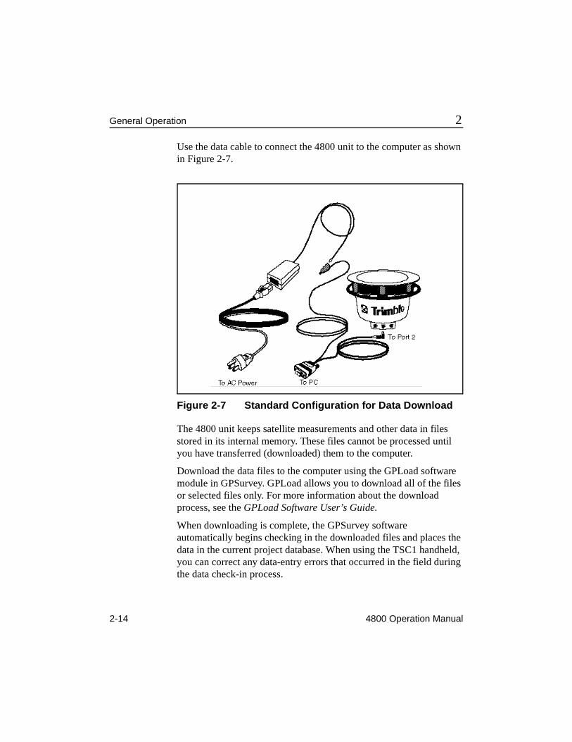
Use the data cable to connect the 4800 unit to the computer as shown in Figure 2-7.
Figure 2-7 Standard Configuration for Data Download
The 4800 unit keeps satellite measurements and other data in files stored in its internal memory. These files cannot be processed until you have transferred (downloaded) them to the computer.
Download the data files to the computer using the GPLoad software module in GPSurvey. GPLoad allows you to download all of the files or selected files only. For more information about the download process, see the GPLoad Software User’s Guide.
When downloading is complete, the GPSurvey software automatically begins checking in the downloaded files and places the data in the current project database. When using the TSC1 handheld, you can correct any data-entry errors that occurred in the field during the data check-in process.
4800 Operation Manual 2-15
2 General Operation
Backing Up Data
Always make a backup copy of your data files after downloading them from the unit. Trimble recommends you use GPSurvey’s Backup utility for project compression and archival.
See the GPSurvey Software User's Guide for additional information on using the backup and restore options in the GPSurvey software.
Deleting Files
Files stored in the 4800 unit can be deleted in the following ways:
1. Use GPLoad in the GPSurvey software (version 2.3 or above).
2. Use the TSC1 handheld.
3. Press the green power key continuously for 60 seconds. (When using this method, all data is deleted. See Section 2.5, Clearing RAM and File System, for additional details.)
M Warning – Clearing the file system (60-second key press) deletes all data files in the 4800 unit, including files that may not have been downloaded.
2-16 4800 Operation Manual
General Operation 2
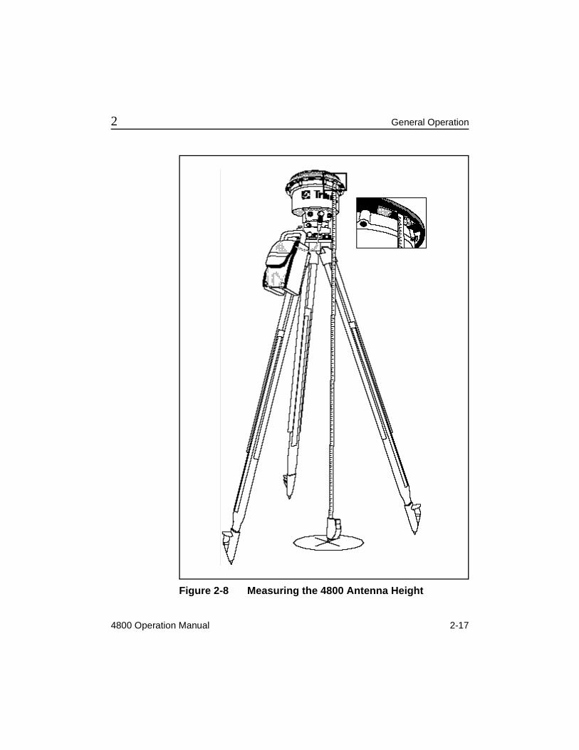
2.9 Measuring Unit HeightAccurate height measurements are essential for meaningful survey results. Mistakes in height measurement are the most common source of error in GPS surveying. Make sure you record the unit height measurements correctly in your field log, as well as the base station or survey mark name, the unit serial number, and the time. The height measurement can be the true vertical height of the unit on a tripod, or the slope height acquired using a tape measure to find the distance from the outer edge of the unit to the survey mark. The GPSurvey software used in processing your files accepts either of these two measurements to calculate the survey mark position precisely.
The 4800 unit is shipped with a tape measure and has tape-measuring tabs on the unit housing. Use these to measure the slope height of the unit when it is mounted on a standard tripod. Connect the tape measure to the tape-measuring tabs, as shown in Figure 2-8, and measure the distance to the survey mark. Be sure to record the value and type of measurement accurately. The offsets are calculated (to the phase center of the 4800 unit) in the GPSurvey software.
* Note – The tape supplied with the 4800 unit reads the distance from the end of the tape to the pointer on the tape case. While measuring slope from the 4800 tab to the monument, record the exact tape value as the slope distance. The GPSurvey software computes the exact height of phase center from your measured slope distance.
4800 Operation Manual 2-17
2 General Operation
Figure 2-8 Measuring the 4800 Antenna Height
2-18 4800 Operation Manual
General Operation 2
2.9.1 Fixed-Height Tripod
A fixed-height tripod has a fixed-height rod attached to the vertical axis to simplify the height measurement process. To set up a fixed-height tripod, place the tip of the measuring rod on the mark and release the tripod's legs, which automatically extend to the ground. Then adjust the tripod until the measuring rod's built-in level bubble is centered in the visible ring, and lock the legs in place.
Since the fixed-height tripod does not require direct measurement of unit height, there is less possibility for height measurement blunders. For this reason, the fixed-height tripod is preferred for control surveys.
2.10 Hardware and Software RequirementsThe following items are the minimum hardware, software, and firmware requirements for using and processing data from the 4800 unit:
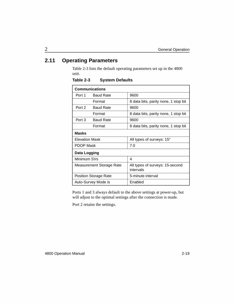
2.11 Operating ParametersTable 2-3 lists the default operating parameters set up in the 4800 unit.
Ports 1 and 3 always default to the above settings at power-up, but will adjust to the optimal settings after the connection is made.
Port 2 retains the settings.
Table 2-3 System Defaults
Communications
Port 1 Baud Rate 9600
Format 8 data bits, parity none, 1 stop bit
Port 2 Baud Rate 9600
Format 8 data bits, parity none, 1 stop bit
Port 3 Baud Rate 9600
Format 8 data bits, parity none, 1 stop bit
Masks
Elevation Mask All types of surveys: 15°
PDOP Mask 7.0
Data Logging
Minimum SVs 4
Measurement Storage Rate All types of surveys: 15-second intervals
Position Storage Rate 5-minute interval
Auto-Survey Mode is Enabled
2-20 4800 Operation Manual
General Operation 2
4800 Operation Manual 3-1
3 Pre-Survey Planning
This chapter outlines the steps necessary to plan a GPS survey project. The procedures are suggestions that are generally applicable to most situations, but can be modified to fit your particular project.
The following tasks are associated with planning a GPS survey:
• preparation
• site reconnaissance
• network design
• survey planning
3.1 PreparationEfficient use of GPS surveying requires an understanding of fundamental surveying principles as well as familiarity with the hardware, software, and field procedures associated with GPS. The functionality of your hardware determines whether to use control survey procedures, such as FastStatic and static, or kinematic survey procedures to observe baselines in the field. Thorough knowledge of the field procedures allows you to perform GPS surveys in the most productive manner, while ensuring high-precision baseline measurements.
3-2 4800 Operation Manual
Pre-Survey Planning 3
Prepare a written plan of your project describing the purpose, scope of work, and ways you expect to collect and use the data. You may find that by collecting data on a few additional points, you can strengthen the network geometry considerably. Also, collecting more data than is needed can yield valuable information for future use. For example, it might enable you to salvage a survey if you find gross errors in the observation of one or more baselines. Determine if observations on additional points are feasible for your current project.
3.2 Site ReconnaissanceSite reconnaissance is usually an indispensable part of field survey planning. It enables you to:
• set or recover survey points to be located during the survey
• note the presence of obstructions that can affect observation scheduling or require that you relocate survey points
• obtain permission to enter the job site from private property owners
• determine the best way to reach each survey station, in any type of weather and at any time of the day or night
• draw maps and write directions so that the survey crew can reach the job site and find the points to be observed
• estimate travel time between stations
3.3 Network DesignA good network design is imperative for a successful control survey campaign. Even in cases where GPS is used for topographic purposes, control points are required to tie the project to a common reference frame. Extra control points also act as reinitialization points if postprocessed or real-time kinematic procedures are to be used.
4800 Operation Manual 3-3
3 Pre-Survey Planning
When designing your network, make a map of the stations, including both fixed-control and unknown points to be observed. Scale the map correctly, as distance between points is an important factor. Also, create an observation schedule that considers both the observation time for each station and the travel time between the stations.
3.4 Survey PlanningCreate a project in the GPSurvey software. This automatically creates the subdirectories required for all further operations associated with the project and initializes a new project database.
* Note – Before you can use the GPSurvey software, you must install it and perform the product activation procedure. See the GPSurvey Software User’s Guide for instructions.
3.4.1 Project Management
The project management portion of the GPSurvey processing environment contains the facilities for the day-to-day management of projects. Use the project management options to perform the following:
• create a new project
• open existing projects
• modify project parameters
• close a project
• delete a project
• review project status
• back up, restore, and check the project database
For more specific information concerning the project management module of GPSurvey, see the GPSurvey Software User's Guide.
3-4 4800 Operation Manual
Pre-Survey Planning 3
3.4.2 Check Satellite Availability
The GPSurvey software Quick Plan / Plan module provides the environment for planning the field observation portion of the project. Either of these modules allow you to:
• create field observation sessions and define all of the stations you want to observe
• enter information from the obstruction diagrams you drafted on your visit to each survey station
• compute the field observation times required based on the SV and local conditions
Use the Plan module to save obstruction and session information to the project database. The Plan module can generate several types of graphs and reports to help you plan field observations. These include displays of satellite azimuth over time, satellite elevation over time, satellite constellation changes, and skyplot (satellite tracks as seen from a station). The skyplot includes outlines of any curtains you defined to describe obstructions.
For more detailed information about the capabilities of GPSurvey's planning software, and the functional differences between Quick Plan and Plan, refer to the Quick Plan / Plan Software User’s Guide.
4800 Operation Manual 4-1
4 In the Field - Control Surveying
This chapter contains a summary of the steps involved in carrying out a GPS survey project using control surveying methods. Refer to the GPSurvey software documentation and other Trimble publications to review specific control survey techniques.
Understanding field data collection procedures is critical to performing successful GPS surveys. It is not enough to know how to operate the 4800 unit; you must also understand how to use the unit to gather data to produce baselines with the highest precision and efficiency possible.
4-2 4800 Operation Manual
In the Field - Control Surveying 4
4.1 Control Surveying DescriptionThe purpose of a control survey is to produce coordinates on selected survey points at a specified level of precision. This level of precision is set high enough that propagated error in subsequent surveys will continue to be within the tolerances or requirements of the overall project standards. To ensure this high level of precision, GPS control surveys use procedures that may be more time-consuming than other GPS surveys.
The two types of data collection techniques suggested for control surveys are Static surveying and FastStatic surveying. Each of these procedures requires that at least two receivers log simultaneous observations of four or more satellites for a specified minimum time. Using the known control information and the baselines computed from your GPS field observations, the GPSurvey postprocessing software can derive coordinates throughout the network.
* Note – Always adjust your survey networks. The direct results of GPS postprocessing are GPS baselines and unadjusted coordinates—insufficient for standard survey procedures. Use the GPSurvey network adjustment option (TRIMNET Plus™) to complete this step.
4.1.1 Static Surveying
Static surveying is the most precise surveying procedure, and the slowest. It requires observations of at least four common satellites for a period of 45 to 60 minutes. It yields baselines that are precise to±5 mm + (1 ppm times baseline length), assuming more than five satellites being tracked continuously. Precise ephemeris and meteorological data may be necessary to achieve this high accuracy, depending on conditions at the time of observation. The 4800 unit performs dual-frequency static surveys.
4800 Operation Manual 4-3
4 In the Field - Control Surveying
4.1.2 FastStatic Surveying
FastStatic surveying is a less precise, but faster, procedure. It requires simultaneous observations of four or more satellites for a period of 8 to 20 minutes and yields baseline components with precision that approaches Static, depending on the number of common SVs, SV geometry, ionospheric conditions, and so on. The FastStatic precision is a function of occupation time and observation conditions. FastStatic surveying is normally limited to operations with baselines of approximately 20 km or less, and is more sensitive to cycle slips and high PDOP (reflecting poor satellite geometry) than static surveying.
4-4 4800 Operation Manual
In the Field - Control Surveying 4
4.2 Basic Survey Project StepsThe main task associated with performing a GPS survey is the collection of the field data, also known as baseline observation.
Field techniques can vary, depending on the required precision of the project, topographic features and obstructions, accessibility, and many other items. However, there are a number of field procedures that are common to all GPS surveys.
These procedures are suggestions and can be modified to fit your particular project, but they are generally applicable to most situations. The basic steps are:
1. Set up the 4800 units on the survey marks.
2. Connect the 4800 unit to the power source (for example, 6AH battery).
3. Measure the 4800 unit antenna heights.
4. Record the height, point ID, unit serial number, and start time in the field log.
5. Begin the baseline observations by turning on the 4800 units and verify they are logging data.
6. Monitor the LEDs and make sure the 4800 unit is tracking (at least) four satellites and that no major losses of lock occur.
7. Based on the number of satellites tracked and the type of survey performed, make sure sufficient time has elapsed before turning off the unit to end the session.
4800 Operation Manual 4-5
4 In the Field - Control Surveying
* Note – Pay close attention to procedures for measuring instrument height. Accurate height measurements are essential for meaningful survey results. Mistakes in height measurement are the most common source of error in GPS surveying. Make sure to record the instrument height measurements correctly in your field log, as well as the base station or survey mark name, the unit serial number, and the time. Fixed-height tripods are recommended to reduce the possibility of blunders caused by incorrect height measurement.
The height measurement can be the true vertical height of the instrument on a tripod, or the slope height acquired using a tape measure to find the distance from the outer edge of the unit to the survey mark. The GPSurvey software, used in processing your files, accepts either of these two measurements to calculate the survey mark position.
4-6 4800 Operation Manual
In the Field - Control Surveying 4
4.3 FastStatic Surveying MethodsFastStatic surveying is identical to static surveying except that you do not stay as long on each point. FastStatic surveying requires simultaneous observations of four or more satellites. Data collection time is typically 8 to 20 minutes, depending on atmospheric conditions and the number of satellites available.
FastStatic surveying yields baseline components with precision that approaches Static, depending on the number of common SVs, SV geometry, ionospheric conditions, and so on. The FastStatic precision is a function of occupation time and observation conditions. Baseline length is assumed to be 20 km or less. The procedure is more sensitive to cycleslips and high PDOP than static surveying.
4.3.1 Required Equipment and Software
A FastStatic survey requires at least two 4800 units. FastStatic survey results are postprocessed with the GPSurvey software.
4.3.2 Setting Up the Equipment and Running the Survey
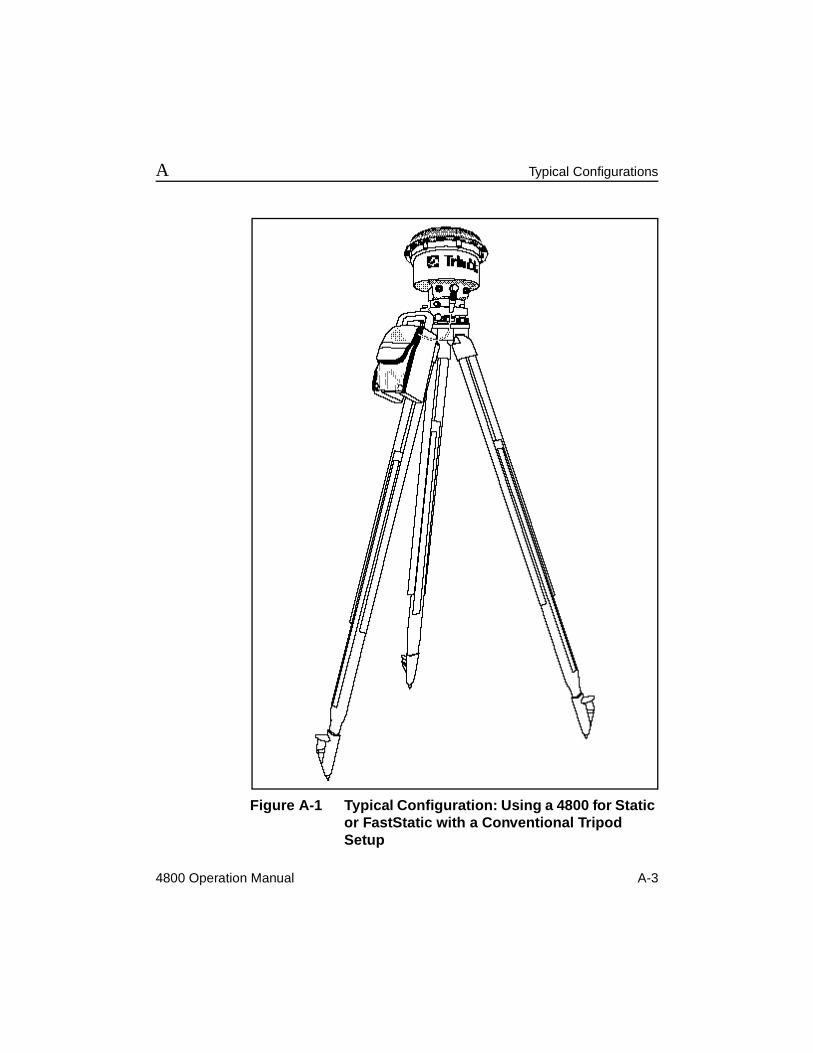
The 4800 unit is mounted on either a tripod, as shown in Figure 4-1, or a PowerLiTE™ pole with Composite bipod, as shown in Figure 4-3. This section describes the method for mounting the unit on a tripod and running the survey.
4800 Operation Manual 4-7
4 In the Field - Control Surveying
Figure 4-1 4800 Mounted on a Tripod
4-8 4800 Operation Manual
In the Field - Control Surveying 4
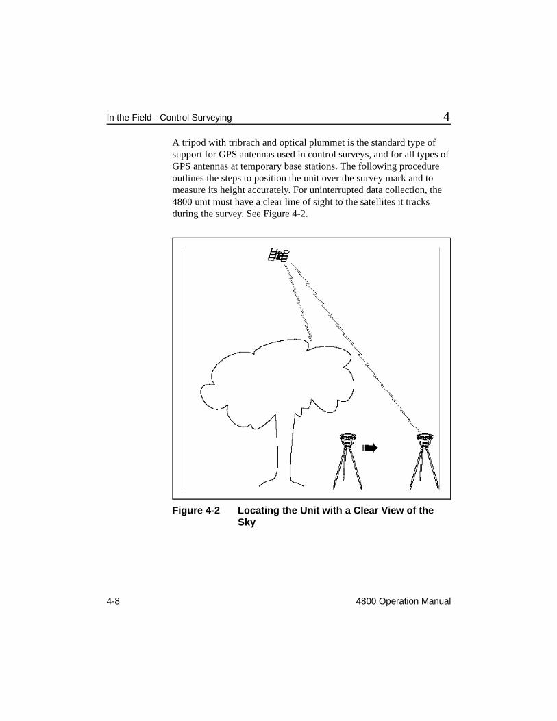
A tripod with tribrach and optical plummet is the standard type of support for GPS antennas used in control surveys, and for all types of GPS antennas at temporary base stations. The following procedure outlines the steps to position the unit over the survey mark and to measure its height accurately. For uninterrupted data collection, the 4800 unit must have a clear line of sight to the satellites it tracks during the survey. See Figure 4-2.
Figure 4-2 Locating the Unit with a Clear View of the Sky
4800 Operation Manual 4-9
4 In the Field - Control Surveying
Making an Observation
Set up the 4800 unit and run the FastStatic survey as described in the following steps:
1. Set up the tripod over the survey mark. The top of the tripod should be roughly at eye level. This makes it easier to adjust, and also reduces the risk of signal multipath from nearby objects.
2. Screw the tribrach adapter into the 4800 unit. Seat the adapter on the tribrach and clamp the assembly to the tripod.
3. Connect the 4800 unit to a power source (for example, a 6AH battery).
4. Position and level the tripod precisely over the survey mark.
5. Measure the 4800 antenna height using the tape measure shipped with the unit. Hook the tape measure to the tape measuring tab on the unit case and measure the exact distance to the survey mark, as shown in Figure 2-8, Measuring the 4800 Antenna Height.
* Note – The tape supplied with the 4800 unit reads the distance from the end of the tape to the tip of the pointer on the tape case. Measure from the 4800 unit tab to the monument and record the exact tape value as a slope distance.
6. Record the slope height measurement, the base station or survey mark name, the unit serial number, and the time that you started the session in your field log. If you know the true vertical height of the unit (if you were using a fixed-height tripod instead of a conventional tripod), record that in your field log. If using a TSC1 handheld, this data is typed in before the beginning of the observation and is stored electronically within the data file.
4-10 4800 Operation Manual
In the Field - Control Surveying 4
* Note – The hardware and setup procedures for base stations and rovers are the same.
7. Repeat steps 1 through 6 to set up one or more base stations (also called reference units) at reference marks whose WGS-84 or NAD-83 coordinates are known with sufficient accuracy for your purposes.
F Tip – When measuring the 4800 unit at the start of the session, read the units in U.S. Survey feet, and at the end of the session read the metric side of the tape. Convert the US Survey units to metric and compare. This helps catch measurement blunders.
8. Repeat steps 1 through 6 to set up one or more rovers (survey units) at survey marks whose coordinates are to be determined.
9. Turn each unit on by pressing the Power button.
10. Observe the indicator LEDs on each unit’s control panel to verify the unit is operating properly (refer to Chapter 2).
11. Wait until the yellow LED on a unit blinks slowly, then turn off the unit.
12. Move the unit to the next survey mark and repeat the previous steps to set up the 4800 unit and begin the next session.
4800 Operation Manual 4-11
4 In the Field - Control Surveying
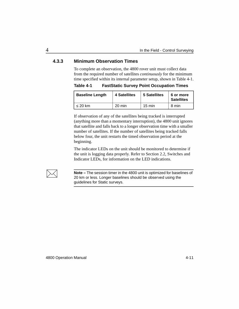
4.3.3 Minimum Observation Times
To complete an observation, the 4800 rover unit must collect data from the required number of satellites continuously for the minimum time specified within its internal parameter setup, shown in Table 4-1.
If observation of any of the satellites being tracked is interrupted (anything more than a momentary interruption), the 4800 unit ignores that satellite and falls back to a longer observation time with a smaller number of satellites. If the number of satellites being tracked falls below four, the unit restarts the timed observation period at the beginning.
The indicator LEDs on the unit should be monitored to determine if the unit is logging data properly. Refer to Section 2.2, Switches and Indicator LEDs, for information on the LED indications.
* Note – The session timer in the 4800 unit is optimized for baselines of 20 km or less. Longer baselines should be observed using the guidelines for Static surveys.
Table 4-1 FastStatic Survey Point Occupation Times
Baseline Length 4 Satellites 5 Satellites 6 or moreSatellites
≤ 20 km 20 min 15 min 8 min
4-12 4800 Operation Manual
In the Field - Control Surveying 4
4.4 Static Surveying MethodsStatic surveying is the most precise surveying procedure a 4800 unit can perform; however, it requires a longer occupation time at each station. The occupation time required for a static survey depends on many factors. Trimble recommends an occupation time of at least 45 minutes during times when five or more satellites are available, or 60 minutes during times when only four satellites are available. The Plan or Quick Plan module can help you determine satellite availability at a specified site and time.
4.4.1 Equipment and Software Required
A static survey requires at least two 4800 units, each mounted on a tripod. The GPSurvey software is recommended for postprocessing static survey results.
4.4.2 Setting Up the Equipment and Running the Survey
The 4800 unit is mounted on either a tripod, as shown in Figure 4-1, or a PowerLiTE pole with Composite bipod, as shown in Figure 4-3. This section describes the method for mounting the unit on a tripod and running the survey.
A tripod with tribrach and optical plummet is the standard type of support for GPS antennas used in control surveys, and for GPS antennas at temporary base stations. The following procedure outlines the steps required to position the unit over the survey mark and to measure its height accurately. To facilitate uninterrupted data collection, the 4800 unit should also have a clear line of sight to the satellites it tracks during the survey, as shown in Figure 4-2.
4800 Operation Manual 4-13
4 In the Field - Control Surveying
Set up the 4800 unit and run the Static survey as described.
Perform steps 1-12 as outlined in Making an Observation, page 4-9, and then continue as follows:
13. Wait for 45 to 60 minutes before turning the unit off. The yellow LED will begin to blink slowly during this observation period; however, data continues to be logged until the unit is turned off.
14. Move the unit to the next survey mark and repeat the previous steps to set up the 4800 unit and begin the next session.
* Note – Be sure to specify in your field log whether an antenna height measurement is slope distance or true vertical. Typically, with standard tripods the measurement is slope distance, and with fixed-height tripods it is true vertical or to "bottom of antenna mount."
4.4.3 Static Survey Times and Distances
Point occupation times for static surveying depends on the number of satellites available and the length of the baseline being measured. The recommended occupation times are between 45 and 60 minutes depending on baseline lengths.
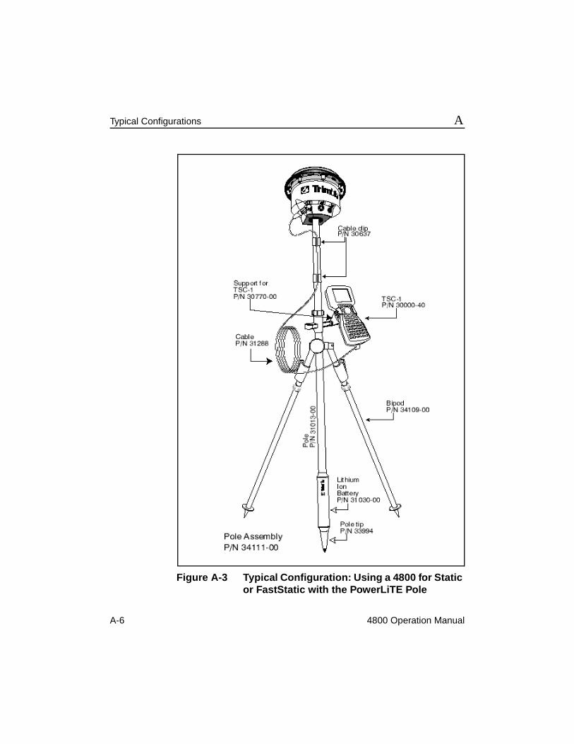
4.4.4 Setting Up a Rangepole
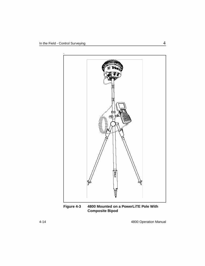
The Trimble PowerLiTE pole with Composite bipod, shown in Figure 4-3, is the recommended support for 4800 rovers in operations with moderate precision requirements and short to moderate observation times (for example, kinematic surveys and some FastStatic surveys).
4-14 4800 Operation Manual
In the Field - Control Surveying 4
.
Figure 4-3 4800 Mounted on a PowerLiTE Pole With Composite Bipod
4800 Operation Manual 5-1
5 Back in the Office with Postprocessed Data
This chapter contains a summary of the steps required for postprocessing GPS survey data. Familiarity with these steps and knowledge of the postprocessing software aids in the planning and reduction of your baseline observations, as well as the management and output of your project. The following procedures are suggestions and can be modified to fit your particular project, but they are generally applicable to most situations.
The tasks associated with postprocessing GPS survey data are the following:
• Open a project
• Download the data from the 4800 unit
• Check in data to the project database and review the field input
• Back up the downloaded data
• Perform the baseline processing
• Analyze the results of processing
• Adjust the network and produce final coordinates
5-2 4800 Operation Manual
Back in the Office with Postprocessed Data 5
5.1 Open a ProjectBefore downloading the data from the receivers, you must open a project in GPSurvey. If you used the Plan utility within the GPSurvey software to plan the project, you created this project during mission planning. (This is not the case if you used QuickPlan.)
5.2 Download DataA GPS receiver keeps satellite measurements and other data in files stored in its internal memory. GPSurvey cannot process the data until you transfer (download) these files to the computer.
Download files into the open project using GPSurvey’s GPLoad utility. This program allows you to download all of the files in a receiver or selected files only. You can also import files that were already transferred from the receiver to a directory outside the current project, solution files from another project, or real-time surveying files from a data collector.
For more information about the downloading process, see the GPLoad Software User’s Guide.
4800 Operation Manual 5-3
5 Back in the Office with Postprocessed Data
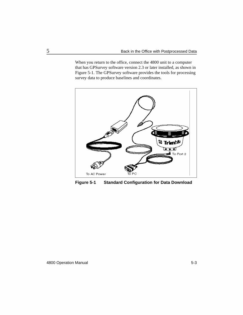
When you return to the office, connect the 4800 unit to a computer that has GPSurvey software version 2.3 or later installed, as shown in Figure 5-1. The GPSurvey software provides the tools for processing survey data to produce baselines and coordinates.
Figure 5-1 Standard Configuration for Data Download
5-4 4800 Operation Manual
Back in the Office with Postprocessed Data 5
5.2.1 File Management Inside the 4800
The 4800 unit automatically assigns a filename and creates a tracking session file when the unit is tracking four or more satellites. Each filename identifies the specific unit by serial number, lists the GPS date, and file sequence number as follows:
AAAABBBC
where:
AAAA = the last four digits of the unit serial number
BBB = GPS date code (Julian day, e.g., Jan 1 = 001, Dec 31 = 365)
C = session sequence number (0 - 9, A - Z}
This numbering scheme allows up to 36 session files to be uniquely numbered. If more than 36 session files are recorded, the filenames for all session files after number 36 (Z) are identical, but each file has a unique time code to identify it from previous files.
4800 Operation Manual 5-5
5 Back in the Office with Postprocessed Data
5.3 Check In and Verify Field InformationThe GPSurvey data check-in program has several parameters that control the process of transferring data to the project database. You can set criteria for defining station names and station identifiers, and have the software do some automatic error detection and correction as well. Check-in is the place where you enter any station information you recorded in the field log, but were unable to enter into the receiver.
Before beginning any baseline processing, make sure the information you entered is correct. Incorrect station information, such as station names or antenna heights, causes erroneous results during baseline processing.
You can also use the data check-in program to edit and view any data entered, such as antenna heights and station information. Use your field notes to compare the actions in the field with what is present in the data set. Be sure to verify the station names and the antenna-height entries for each occupation in every 4800 unit.
Be especially careful when specifying the type of antenna-height measurement (uncorrected or true vertical). If you are entering a true vertical antenna-height measurement, be aware that GPSurvey makes no corrections to this value throughout the data reduction.
The GPSurvey software supports the use of the TSC1 handheld with Survey Controller™ firmware, which is required for a kinematic survey with the 4800 unit. If you used a TSC1 handheld in the field, there is more information to check in—and more sources of potential errors. Check the descriptive information, such as station names, as well as the surveying data. Checking and double-checking at this stage can help to avoid typographical or occupational blunders being carried into the subsequent processing phase of the data reduction.
For more information about verifying station information, see the GPSurvey Software User’s Guide.
5-6 4800 Operation Manual
Back in the Office with Postprocessed Data 5
5.4 Back Up DataAlways make a backup copy of data files after downloading. Trimble recommends that you use GPSurvey’s Backup utility for project compression and archival.
See the GPSurvey Software User's Guide for additional information on using the backup and restore options in the GPSurvey program.
5.5 Process the BaselinesUse the GPSurvey software module, WAVE (Weighted Ambiguity Vector Estimator), to reduce the field observations and produce baselines. You do not have to be concerned that the data may have been collected using a combination of field techniques. The WAVE module automatically recognizes and distinguishes between static, FastStatic, and kinematic data files.
See the WAVE Software User’s Guide for complete information on baseline processing.
5.6 View the Baseline ResultsThe GPSurvey software also provides the facility to view the observed stations and processed baselines in a network map. Use additional options to perform loop closures and view the detailed information in the closure log, or generate a baseline log with a list of solution files associated with selected baselines.
See the GPSurvey Software User’s Guide for complete information on the network map viewing options.
4800 Operation Manual 5-7
5 Back in the Office with Postprocessed Data
5.7 Adjust the NetworkNetwork adjustment is the most important tool in judging the overall integrity of your observations and survey network. Just because a baseline can be processed in GPSurvey does not mean that the baseline fits within your survey network. It is not enough for a baseline to be statistically precise; it must fit into the network of baselines that you have observed.
By default, the coordinates output by WAVE are WGS-84 datum coordinates—you will probably want to transform these coordinates to some other, more meaningful, local datum. Use the network adjustment process and tools to assist with the tasks of datum transformations, geoid modeling, and quality control.
TRIMNET Plus, the network adjustment program that typically comes bundled with the GPSurvey software, can combine GPS, terrestrial, and geoid observations in network adjustment computations.
5.7.1 Create Project Reports
Utility options available in the GPSurvey software can be used to create, preview, and print the following customized summaries of your project:
• Project: general project information
• Station: information about selected stations in the project
• Baseline: one-line summaries of processing results for selected baselines
• Baseline solution: brief processing information for selected baselines
• Detailed baseline: detailed processing information for selected baselines
5-8 4800 Operation Manual
Back in the Office with Postprocessed Data 5
4800 Operation Manual 6-1
6 In the Field - Real-Time Kinematic Surveying
This chapter contains a brief discussion of the steps involved in executing a GPS survey project using real-time kinematic surveying methods. Refer to the Survey Controller Reference Manual and Survey Controller Field Guide for version 6.0, and the Trimble Survey Office Software User’s Guide for more information on equipment operation and RTK (as well as postprocessed kinematic) survey techniques.
* Note – A Trimble TSC1 handheld with Survey Controller firmware is required to perform a real-time or postprocessed kinematic survey with the 4800 unit. The Survey Controller software on the handheld provides an interface to the GPS unit, allowing you to specify beginning and ending times for stop-and-go occupations or continuous kinematic segments. The Survey Controller also allows you to enter point names, feature codes and antenna heights while you are occupying a station or while you are moving.
For RTK, the base receiver and each rover must have its own dedicated radio and antenna to maintain the required communications link between base and rover.
6-2 4800 Operation Manual
In the Field - Real-Time Kinematic Surveying 6
6.1 Real-Time Kinematic (RTK) Surveying DescriptionReal-time kinematic surveying has three basic physical components:
• GPS base station
• GPS rover
• Radio link between the base and the rover
The radio link transmits the GPS observations (data) from the base receiver to the rover. The roving receiver then combines the base station data with the rover GPS data to process baselines and produce coordinates at the rover in real-time.
A significant feature of RTK is the ability to work in local coordinates. This feature is possible only if a calibration has been performed for the local system, where the calibration defines the transformation parameters, or mathematical relationship, between the GPS coordinate system (WGS84) and the local coordinate system.
Because RTK is, by definition, a kinematic procedure, it shares the same initialization requirements as a postprocessed kinematic survey. You must initialize the roving receiver at the beginning of the survey and maintain lock on at least four of the same satellites that the base receiver is tracking, while performing a successful RTK survey. If there is a loss of lock (interruption in tracking of at least four common satellites), you must re-initialize the rover before proceeding.
When configured for RTK, the 4800 unit is capable of on-the-fly initialization, or initialization while moving. This allows for regaining initialization while walking or moving from one point to the next, assuming a clear view to the sky. This initialization method requires tracking at least five common satellites at base and rover.
You can perform an entire GPS survey using only RTK methods, but it is also possible to combine the results of a postprocessed survey with RTK. The basic RTK requirements are the same in each of these cases, but the sequence of the steps varies. The example in Section 1.8, Sample Field Survey - Postprocessed, illustrated one approach to combining postprocessed and RTK surveys.
4800 Operation Manual 6-3
6 In the Field - Real-Time Kinematic Surveying
6.1.1 RTK Survey
The following basic steps are required to conduct a real-time survey, when there has been no previous GPS conducted on site:
1. Set up the base receiver with radio modem and radio antenna.
2. Start the base receiver using the TSC1 handheld.
3. Set up the roving receiver with radio and radio antenna.
* Note – The 4800 unit can be configured with an internal RTK radio modem. If no internal radio modem exists, you must connect one externally to port 3 of the 4800 unit.
4. Start the roving receiver using the TSC1 handheld.
5. Initialize the roving receiver.
6. Locate control points with rover.
7. Perform in-field calibration in the TSC1 handheld.
8. Proceed with RTK survey.
Before performing the calibration, control points are located relative to the base receiver in a system approximating the GPS coordinate system (WGS84). After the calibration has been successfully performed, all results are presented in the local coordinate system.
This is one advantage to using RTK exclusively: one trip to the job site is eliminated. With RTK, the control points can be located on the first trip to the job site using RTK and in-field calibration. This avoids having to perform a postprocessed control survey, return to the office, process the data and adjust the coordinates, and then return to the field to perform the RTK survey.
The disadvantage to this approach is the absence of a network adjustment for the control stations or any other stations in the survey network. Also, there is no existing network of GPS baselines for possible initialization, so the only option to begin the RTK survey is with the RTK initializer.
6-4 4800 Operation Manual
In the Field - Real-Time Kinematic Surveying 6
4800 Operation Manual A-1
A Typical Configurations
This appendix contains the typical configurations for using the 4800 unit in the field as well as for downloading the field data.
A.1 Tripod Setup: Field Checklist and ConfigurationTable A-1 lists the items required for each 4800 unit setup using a conventional tripod.
Table A-1 Items Required for Conventional Tripod Setup
Part Name Part Number
4800 unit varies, depending on options
4800 softcase 33849-00
6 AH battery 32364-00
Conventional Tribrach 12179
Laser Tribrach 33848
Tribrach adapter 12180
Tripod 12178
H.I. tape 27402-00
A-2 4800 Operation Manual
Typical Configurations A
Table A-2 lists optional items.
Table A-3 lists additional items recommended, but not supplied by Trimble.
Figure A-1 illustrates the 4800 unit setup when using a conventional tripod. Figure A-2 illustrates the 4800 unit setup when using a conventional tripod and a Lithium ion battery.
Table A-2 Optional Items
Part Name Part Number
10 AH battery 32365-00
PowerLiTE Pole with composite bipod 34111-00
Fixed height tripod varies, depending on height
PowerLiTE Lithium ion battery 31030-00
PowerLiTE battery cable 33914-00
PowerLiTE battery pouch 33993
Table A-3 Recommended Items Not Supplied by Trimble
Item Function
Directions to each station
Keeps crews on schedule, minimizes time lost due to unforeseen local traffic or road conditions
Station descriptions
Facilitates station recovery and occupation
Communication (radio) devices
Allows communication between crews
Field logs Necessary to record station names, antenna height measurements, unit serial numbers, etc.
4800 Operation Manual A-3
A Typical Configurations
Figure A-1 Typical Configuration: Using a 4800 for Static or FastStatic with a Conventional Tripod Setup
A-4 4800 Operation Manual
Typical Configurations A
Figure A-2 Using a 4800 for Static or FastStatic with a Conventional Tripod and Lithium Ion Battery
4800 Operation Manual A-5
A Typical Configurations
A.2 Rangepole Setup: Field Checklist and Configuration
Table A-4 lists items required for each 4800 setup using a rangepole.
Table A-5 lists optional items.
Figure A-3 illustrates the 4800 unit setup when using a rangepole.
Table A-4 Items Required for Rangepole Setup (Control Work)
Part Name Part Number
4800 unit varies, depending on options
4800 softcase 33849-00
PowerLiTE Pole with composite bipod 34111-00
PowerLiTE Lithium ion battery 31030-00
Table A-5 Optional Items
Part Name Part Number
6 AH battery 32364-00
10 AH battery 32365-00
4800 softcase 33849-00
H.I. tape 27402-00
Additional Lithium ion battery 31030-00
Battery length extension 34135-00
Lithium ion battery pouch 33993
PowerLiTE Pole carrying case 34110
TSC1 with Survey Controller 30000-40
TSC1 Cable 31288
A-6 4800 Operation Manual
Typical Configurations A
Figure A-3 Typical Configuration: Using a 4800 for Static or FastStatic with the PowerLiTE Pole
4800 Operation Manual A-7
A Typical Configurations
Table A-6 lists the functions of items in the PowerLiTE pole setup.
Table A-6 Functions of Items in PowerLiTE Pole Setup
Part Name Function
Pole 1) Support and positioning of the 4800 unit over the survey mark
2) Conduit for the power cabling from the 4800 unit to the lithium ion battery
Bipod Allows hands-free support and positioning of the 4800 unit over the survey mark
Cable clip Secures the TSC1 cable to the pole
Pole extension Adds a pre-defined length to the pole (equal to the length of the Lithium ion battery)
Pole tip Facilitates precise placement of the pole on the survey mark (point is standard plumb bob point)
Lithium ion battery
Supplies power to the 4800 unit
TSC1 Bracket Enables the TSC1 to be fastened to the pole
A-8 4800 Operation Manual
Typical Configurations A
A.3 Preparing to Download Field Data from the 4800Figure A-4 shows the connections required to download field data from the 4800 unit.
Figure A-4 Making the Connections when Downloading Field Data from the 4800
To download field data from the 4800 unit:
1. Connect the 7-pin end of the LEMO cable (P/N 32345) to Port 2 of the 4800 unit. See Figure A-4.
2. Connect the RS-232 end of this cable to the serial port of the computer.
3. Connect the cable that comes with the power supply (P/N 30413) into the loose end of the download cable (P/N 32345).
4800 Operation Manual A-9
A Typical Configurations
4. Connect the power cord (P/N 11017) into the power supply (switching AC adaptor, P/N 30413).
5. Connect the power supply (switching AC adaptor) to an AC outlet.
Figure A-5 shows the connections required to download field data using the 4-pack charger unit for power.
Figure A-5 Downloading Field Data from the 4800 Using the 4-Pack Charger Unit
F Tip – When using LEMO connectors, look for the red dot on the cable end and the red hash mark on the hardware port. If these two marks are aligned the cable should slip easily into the port.
A-10 4800 Operation Manual
Typical Configurations A
A.4 External Power OptionsThere are a number of external power options. These are discussed in the following sections.
A.4.1 6 AH battery
The rechargeable, portable 6 AH battery powers the 4800 unit for approximately eight hours. The battery connects to the unit using a cable with a 7-pin (0-shell) LEMO connector. The connector plugs into port 2. The 6 AH battery is standard with a GPS Total Station®
4800 or postprocessed bundle.
A.4.2 10 AH battery
The rechargeable, portable 10 AH battery powers the 4800 unit for approximately 14 hours. The battery comes in a carrying bag with a fused cable that has a 7-pin (0-shell) LEMO connector. The connector plugs into port 2. The 10 AH battery is available as an option.
A.4.3 PowerLiTE battery, cable and pouch
For control work, the PowerLiTE battery can be connected directly to port 2 of the 4800 through the PowerLiTE battery cable. The battery can be attached to the tripod with the provided pouch.
I Caution – When the temperature falls below 10°F (-12°C) the PowerLiTE battery should not be used in Port 2. Port 2’s shutdown cutoff is set at 10.5VDC in order to avoid permanent damage to a lead acid battery.
4800 Operation Manual A-11
A Typical Configurations
A.4.4 Other Trimble power supplies
To use other Trimble power supply options that you currently own or plan to purchase in the future, use P/N 32959 to make the connection from a 0-shell 7-pin LEMO to a 1-shell 5-pin LEMO device (for example, an Office Supply Module or OSM).
A.5 Internal RadioTo determine whether the 4800 unit has an internal radio installed look for the stickers (as shown in Figure A-6) on the bottom of the 4800 unit.
Figure A-6 4800 Unit with Internal Radio
A-12 4800 Operation Manual
Typical Configurations A
4800 Operation Manual B-1
B Specifications
The following tables contain physical and technical specifications for the 4800 unit.
Azimuth 1 arc second + 5/ (baseline length in kilometers)
*Assumes 5 satellites (minimum) tracked continuously using the recommended sur-vey procedures and utilizing the L1 and L2 signals at all sites; precise ephemerides and meteorological data may be required. FastStatic is a function of occupation time and observation conditions.
Table B-2 4800 Unit Physical Specifications
Size 9" (D) x 7" (H)
23cm (D) x 17.8cm (H)
Weight 4.1 lbs. (1.8 Kg) 4800 only, no radio
Power 6 watts typical, 10.5 to 20 VDC
Operating Temperature -40°C to +55°C (-40°F to +131°F)
Storage Temperature -40°C to +75°C (-40°F to +167°F)
Humidity 100% fully sealed, buoyant
Casing Dust proof, splash proof, water proof and shock resistant
Shock 2m pole drop
B-2 4800 Operation Manual
Specifications B
Table B-3 4800 Unit Technical Specifications
Tracking 9 channels L1 C/A code, L1/L2 full cycle carrier. Fully operational during P-code encryption.
Signal Processing Maxwell architecture; very low-noise C/A code processing; Supertrak multibit GPS signal processing; multipath suppression: full 32-bit microprocessor
Communications Dual RS-232 ports for serial input and data collector control. Baud rates up to 38,400; Dedicated RS232 serial port for external radio communications
Optional Output NMEA-0183: GGK, GGA, ZDA, GST, VTG Formats
Trimble General Serial Output Format
Requires Configuration-Toolbox software
Table B-4 4800 Unit Electrical Specifications
Power Nominal 10.5 to 20 VDC, 2 DC power inputs
Nominal 6W (4800 only), 7W (while operating internal radio modem and TSC1 handheld)
Battery >8 hours typical with 6 AH battery
>4 hours typical with PowerLite Lithium-ion battery
GPS antenna Integrated Micro-centered GPS antenna and lightweight groundplane
Certification FCC, DOC, and CE Mark approved
4800 Operation Manual C-1
C NMEA-0183 Output
When the NMEA-0183 output is enabled, messages can be produced to aid integration with other sensors.
C.1 Message ElementsAll messages conform to the NMEA-0183 Version 2.0 format. All begin with dollar sign ($) and end with a carriage return and a line feed. Data fields follow comma (,) delimiters and are variable in length. Null fields still follow a comma delimiter but contain no information.
The optional checksum field is the last field in a message and follows the asterisk (*) delimiter. The checksum is the 8-bit exclusive OR of all characters in the message, including the commas, between but not including the comma and asterisk delimiters. The hexadecimal result is converted to two ASCII characters (0-9, A-F). The most significant character appears first.
C-2 4800 Operation Manual
NMEA-0183 Output C
C.1.1 Fields and Delimiters
Each message consists of:
• message ID consisting of $GP followed by the message type For example, the message ID of the ALM message is $GPALM.
• comma
• number of fields that depends on the message type, separated by commas
• asterisk
• checksum
An example of a simple message with six fields plus the message ID and checksum follows:
$GPZDA,152145,21,05,1993,-7,00*50
C.1.2 Latitude and Longitude
Latitude is represented as ddmm.mmmm. Longitude is always represented as dddmm.mmmm, where direction (north, south, east, or west) is presented in a separate field.
• dd or ddd is degrees
• mm.mmmm is minutes and decimal fractions of minutes
C.1.3 Direction
Direction is a single character: N, S, E, or W for North, South, East, or West
4800 Operation Manual C-3
C NMEA-0183 Output
C.1.4 Time
Time values are in UTC, and are represented as hhmmss, where:
• hh is hours, from 00 to 23
• mm is minutes
• ss is seconds
C.2 Supported MessagesTable C-1 summarizes the set of NMEA messages supported by the 4800 units and shows the page number where detailed information about each message is found.
Table C-1 NMEA Message Summary
Message Function Page
GGA Time, position, and fix related data C-4
GST Position error statistics C-5
PTNL, GGK Time, position, position type and DOP values
C-6
PTNL, PJT Projection type C-8
PTNL, PJK Local coordinate position output C-7
VTG Actual track made good and speed over ground
C-8
ZDA UTC day, month, and year, and local time zone offset
(FIXED)4: Differential, code phase only solution (DGPS)
8 Number of satellites in fix
9 DOP of fix
10 Ellipsoidal height of fix
11 M is fixed text indicating the unit of measure for ellipsoidal height is meters
C-8 4800 Operation Manual
NMEA-0183 Output C
C.2.5 PTNL, PJT: Projection Type
$PTNL,PJT,NAD83(Conus),California Zone 4 0404,*51
Table C-6 describes the fields in the PTNL,PJT message.
C.2.6 VTG: Actual Track Made Good Over and Speed Over Ground
$GPVTG,,T,,M,0.00,N,0.00,K*4E
Table C-7 describes the fields in the PTNL, PJT message.
Table C-6 PTNL,PJT Message Fields
Field Meaning
1 Coordinate system name (can include multiple words)
2 Projection name (can include multiple coordinates)
Table C-7 VTG Message Fields
Field Meaning
1 Track made good (degrees true)
2 T is fixed text that indicates that track made good (prior field) is relative to true north
3 Null field
4 M is fixed text
5 Speed (knots)
6 N is fixed text that indicates that speed is in knots
7 Speed over ground in kilometers/hour (KPH)
8 K is fixed text that indicates that speed over ground is in KPH
4800 Operation Manual C-9
C NMEA-0183 Output
C.2.7 ZDA: UTC Day, Month, And Year, and Local Time Zone Offset
$GPZDA,172809,12,07,1996,00,00*45
Table C-8 describes the fields in the ZDA message.
Fields 5 and 6, together, yield the total offset. For example, if field 5 is –5 and field 6 is –15, local time is 5 hours and 15 minutes earlier than GMT.
Table C-8 ZDA Message Fields
Field Meaning
1 Time, in UTC
2 Day, 01 to 31
3 Month, 01 to 12
4 Year
5 Local time zone offset from GMT, 00 to ±13 hours
6 Local time zone offset from, minutes
C-10 4800 Operation Manual
NMEA-0183 Output C
4800 Operation Manual D-1
D Troubleshooting
This appendix contains information about troubleshooting the 4800 unit. If you have trouble using the 4800 unit, check Table D-1 to see if the symptom is described and try using the solution to correct it.
Table D-1, on the following page, lists possible causes and their solutions.
D-2 4800 Operation Manual
Troubleshooting D
Table D-1 4800 Troubleshooting
Symptom Possible Cause Solution
Unit does not turn on.
Unit batteries are low. Replace the batteries.
External power source batteries are low.
Replace or recharge the external batteries. (See Section 2.4.6, Charging the Batteries.)
External power source cable not connected properly or faulty.
Check external power source cable, make sure both ends are securely inserted. Check any in-line fuses.
Unit does not log data.
Insufficient memory to log current session. (Fast blinking yellow LED.)
Use GPLoad software to delete old session files from memory.
Unit cannot track 4 or more SVs. (Fast blinking red LED.)
Check survey mark location for obstructions, trees, buildings, towers.
Unit locked up. Unit needs to be reset.
Level 1
Remove all power
Unit locked up. Unit needs to be reset.
Level 2
Hold button down for 10 seconds at power-up. This resets the battery-backed memory. Stored survey data is not lost. On power-up, the satellite and power LED’s flash simultaneously for 5 seconds.
Unit locked up. Unit needs to be reset.
Level 3
Hold button down for 30 seconds at power-up. All stored survey data is deleted from memory.
4800 Operation Manual E-1
E PowerLiTE Battery Charger Operation
This appendix contains safety information and instructions for using the PowerLiTE battery charger (P/N 31791-00).
Charging a lithium ion battery (P/N 31030-00, 11.1V, 2.4AH), from full discharge to full charge, requires approximately three hours.
E-2 4800 Operation Manual
PowerLiTE Battery Charger Operation E
E.1 SetupConnect the output plug of the AC switching adaptor (P/N 30413) to the input power jack of the charger. Apply AC power of 90 to 264V, 50/60 Hz single phase to the AC power plug of the module.
Figure E-1 4-Pack Charger Setup
4800 Operation Manual E-3
E PowerLiTE Battery Charger Operation
E.2 Charge StatusThe following procedure describes how the PowerLiTE battery charger operates.
1. Insert up to four battery packs into the charger slots. The batteries charge one at a time from left to right. The orange indicator at each occupied position glows, indicating that the battery is electrically connected to the charger. One green indicator flashes when the battery is charging while the other green indicators remain unlit.
2. When the battery is fully charged, the flashing green indicator changes to a continuous glow. The next battery in line begins charging automatically, indicated by the flashing green indicator.
3. Any fully charged battery can be removed from the charger and replaced with a discharged battery at any time. If another battery is in charging mode the discharged battery only indicates electrical contact with a glowing orange indicator. When the currently charging battery is fully charged, the charger resumes operation as described in step 1 and 2.
4. When all batteries are fully charged, the charger continuously checks each battery's condition periodically. If a battery requires more charge, it is charged automatically.
Summaries of the status indicators are as shown in Table E-1:
E-4 4800 Operation Manual
PowerLiTE Battery Charger Operation E
* Note – In protection mode, the battery has zero output voltage. To restore battery to operational mode, remove battery from slot for 5 minutes, and then reinsert. Approximately 2 seconds later, after battery reinsert, the orange and green indicators go on. Now the battery can be used.
E.3 Temperature Warning IndicationThe recommended ambient temperature range for operation is OºC to +50ºC. Should the ambient temperature move out of this range, a red warning indicator light glows, charging stops, and the charger enters sleep mode. (All green and orange indicators dim, except a green power-on indicator.) Sleep mode dissipates minimal power from AC power source to save energy. When ambient temperature re-enters the specified range, the red warning indicator turns off and the charger resumes normal operation.
Table E-1 Status Indicators
Green Indicator Battery Status
OFF Waiting to charge
ON Fully charged. Battery ready for use
FLASH Charging
Orange Indicator Terminal Contact
ON Battery in slot with good electrical contact
OFF Poor terminal pin contact or battery is in protection mode (see Note below)
4800 Operation Manual E-5
E PowerLiTE Battery Charger Operation
E.4 Desktop Power ModuleThe desktop module (P/N 30413) delivers a maximum output capability of +18 VDC at 1.66A with built-in overload and short- circuit protection. This unit is rated to power one 4-Pack Charger (P/N 3179100) and one 2-Pack Charger (P/N 31970-00) simultaneously. This power module and both chargers described in Section E.1, Setup, can remain plugged in continuously.
E.5 Safety InstructionsTo avoid fire, explosion, or leaking electrolyte, the following precautions must be taken.
• Use only Trimble Navigation Limited specified chargers listed in Section E.4, Desktop Power Module.
• Do NOT do the following:
• Submerge battery in any type of liquid.
• Drop battery nor apply mechanical shocks.
• Dispose battery in fire.
• Disassemble, short circuit, deform, alter, nor solder batteries.
• Use battery close to heat source. If strange smell or electrolyte leak is detected, discontinue use and move battery away from heat source.
• Allow electrolyte to contact skin. If contact occurs, immediately rinse with large quantities of running water then seek proper medical attention. Keep out of reach of untrained individuals who have not read this operating manual.
• Use or store batteries above 50ºC.
• When disposing of batteries, cover terminal pins with insulated tape.
E-6 4800 Operation Manual
PowerLiTE Battery Charger Operation E
E.6 Technical Support For more technical product information, question or support, contact Trimble at (800) 827-8000 (in the United States and Canada) or (408) 481-8000.
4800 Operation Manual F-1
F Using WinFLASH
WinFLASH is a software package that communicates with Trimble products to perform various functions, such as:
• software and option upgrades
• diagnostics (for example, retrieving configuration information)
F.1 Installing WinFLASHTo install WinFLASH:
1. Insert the first WinFLASH program floppy disk in the computer’s floppy drive (for example, A:).
2. Type A:setup.exe and follow the on-screen prompts to complete the installation.
A program icon is installed for future use of WinFLASH.
F-2 4800 Operation Manual
Using WinFLASH F
F.2 Using WinFLASH: An ExampleThe program uses a series of screens to guide you through the desired process. An overview of the steps is described in the example below.
This example describes how to retrieve configuration data (for example, serial number and installed options) from a 4800 unit. For more general help, please refer to the WinFLASH on-line help.
1. Start WinFLASH by clicking the program icon.
2. When the Device Configuration screen appears, select the Trimble device and PC serial port the device is connected to, and press Next > . (for example, device = 4800 Receiver, PC serial port = COM2)
The Operation Selection screen appears. The Operations box lists all of the supported operations for the selected device, and the description of each operation is shown in the Description box.
3. Select an operation and press Next > . (for example, Configuration retrieval)
The Settings Review window appears. This screen prompts you to connect the device, suggests a connection method, and then lists the device configuration and operation you selected.
4. If all is correct, select Finish .
Based on the selections shown above, the Configuration Retrieval window appears and shows the status of the operation (for example, “Establishing communication with the 4800. Please wait…”) Once communication is established, the progress bar indicates that a successful link has been established as well as the extent of completion.
Finally the Configuration Information window appears and lists the device specific configuration information (for example, Serial number and installed options).
4800 Operation Manual F-3
F Using WinFLASH
5. Click OK.
The Configuration Retrieval window appears once more and states that the operation was completed successfully.
6. At this point press Menu to select another operation or Exit to quit WinFLASH.
7. If you select Exit , another screen appears stating that this selection causes WinFLASH to terminate. Click OK to quit WinFLASH.
* Note – WinFLASH is a 32-bit application, so the local computer’s operating system must be Windows 95 or Windows NT (it does not run under Windows 3.1 or earlier versions of Windows).
F-4 4800 Operation Manual
Using WinFLASH F
4800 Operation Manual G-1
G Using CommSet
This appendix describes the functions of the CommSet program and outlines a basic example of its use.
G.1 What is CommSet?CommSet is a communications setup utility for configuring Trimble radio modem products. Trimble radio modems can be configured for specific applications or for individual job requirements (for example, selecting the base station's preset radio modem frequency) with this program.
Configuration parameters can be modified as often as necessary and you can check the configuration of a radio modem without making changes. If your radio modem is approved for firmware updates, CommSet is used to download new firmware into the radio modem.
* Note – For optimal performance, all (roving) 4800 unit radio modems need to know the type of radio modem used at the base station when performing an RTK survey. The default setting is Trimmark II. If the base station is using a TrimTalk 450 or TrimTalk 450S, CommSet must be used to change the radio modem settings for each 4800 rover unit involved in the (RTK) survey.
G-2 4800 Operation Manual
Using CommSet G
G.2 Using CommSet: An ExampleThe basic steps to modify or check the configuration on the Trimble radio modem follow:
1. Start CommSet by clicking on the program icon.
The CommSet dialog box appears.
2. Make the connection between the computer (pick a COM port, for example COM2) and the 4800 unit (Port 3).
3. Make sure that the 4800 unit has power.
4. Press Connect in the CommSet dialog box.
The Connecting To Radio dialog box appears.
Completion of the connection is shown by a progress bar and then the Trimble 4800 Radio Properties dialog box appears, with the radio modem’s serial number at the top.
5. At the prompt To change the Trimble 4800’s radio settings: make your selections from the drop-down boxes in lines 1 and 2, and press Set in line 3 to make the changes.
The Setting the Radio dialog box indicates the progress. When complete you are returned to the dialog box in step 1.
* Note – CommSet is a 32-bit application, therefore the local PC's operating system must be either Windows 95 or Windows NT (it will not run under Windows 3.1 or earlier versions).
4800 Operation Manual Index-1
Index
Numerics
10 AH battery A-104800 unit 2-1
applications 2-2control panel 2-2electrical specifications B-2indicator LED functions 2-4mounted on a PowerLiTE
pole 4-14mounted on a tripod 4-7physical specifications B-1technical specifications B-2
4-pack charger setup E-26 AH battery A-10
A
accuracystatic survey (postprocessed) B-1
adjust the network 5-7advantages
GPS surveying techniques 1-3analyzing the results of processing 5-1applications 2-2audience xvii
B
Back In the Office 5-1back up data 2-15, 5-6Base 1 FastStatic Data Logging
Session 1-14Base 3 FastStatic Data Logging
Session 1-15base station or survey mark name 2-16,
4-5baseline observations 4-4
techniques 1-5baseline results
view 5-6basic survey project
steps 4-4batteries
charging 2-11
C
Camcorder Battery Kit 2-8care and use 2-12cautions xxiiicharging the batteries 2-11check in and verify field
information 5-5clearing RAM and file system 2-11COCOM limits 2-12
site reconnaissance 3-1, 3-2skyplot 3-4software and hardware
requirements 2-18specifications B-1
electrical B-2physical B-1
Index-6 4800 Operation Manual
Index
technical B-2standard configuration
data download 2-14, 5-3Static survey
times and distances 4-13Static surveying 1-10, 2-2, 4-2, 4-12
equipment and software required 4-12
methods 4-12station
identifiers 5-5names 5-5
stationary occupations 6-1strengthening network geometry 3-2successful control survey campaign 3-2survey mark 4-8, 4-12survey mark or base station name 2-16,
4-5survey planning 3-1, 3-3survey project
planning 3-1surveys
postprocessed 1-4switches and indicator lights 2-2system defaults 2-19
troubleshooting D-1, G-1unit does not log data D-2unit does not turn on D-2unit is locked up D-2
TSC1 handheld 1-12types of control survey
static surveying 4-2typical configuration
using 4800 for Static or FastStatic with conventional tripod setup A-3
using 4800 for Static or FastStatic with PowerLiTE pole A-6
typical configurations A-1
U
U.S. Department of Commerce 2-12U.S. Department of Defense 1-1unit height measurements 2-16unit serial number 2-13, 2-16, 4-5, 5-4update notes xixuse and care 2-12using CommSet G-1