800-456-7100 I www.paladinlcg.com 503 Gay Street, Delhi, IA 52223, United States of America SERIAL NUMBER: ___________________ Manual Number: OM707 Part Number: 75607 MODEL NUMBER: ___________________ Rev. 2 485 BACKHOE OPERATOR’S MANUAL 10718 7-14-10-3
Transcript
800-456-7100 I www.paladinlcg.com 503 Gay Street, Delhi, IA 52223, United States of America
OPERATING INSTRUCTIONS GENERAL INFORMATION ..................................................................................................................... 22 CONTROLS ............................................................................................................................................ 22 BEFORE YOU START DIGGING ...................................................................................................... 23-24 BASIC DIGGING TECHNIQUES ....................................................................................................... 25-26 SPECIAL APPLICATIONS ................................................................................................................. 26-30 TRANSPORTING ................................................................................................................................... 31 STORAGE .............................................................................................................................................. 32 REMOVAL FROM STORAGE ................................................................................................................. 32
LUBRICATION LUBRICATION SYMBOLS AND DIAGRAM ...................................................................................... 33-34
MAINTENANCE AND SERVICE GENERAL INFORMATION ..................................................................................................................... 35 EVERY 8 HOURS ................................................................................................................................... 35 EVERY 40 HOURS ................................................................................................................................. 35 CONTROL VALVE .................................................................................................................................. 36 REPLACING BUCKET TEETH ............................................................................................................... 36 CHANGING BUCKETS ........................................................................................................................... 36 HOSE ROUTING .................................................................................................................................... 37 CYLINDER SEAL REPLACEMENT (Retaining Ring Type Gland) .................................................... 38-39 CYLINDER SEAL REPLACEMENT (Threaded Type Gland) ............................................................. 40-41
GENERAL COMMENTS� Congratulations�on�the�purchase�of�your�new�BRADCO�product!�This�product�was�care-fully�designed�and�manufactured�to�give�you�many�years�of�dependable�service.�Only�minor�maintenance�(such�as�cleaning�and�lubricating)�is�required�to�keep�it�in�top�working�condition.�Be�sure�to�observe�all�maintenance�procedures�and�safety�precautions�in�this�manual�and�on�any�safety�decals�located�on�the�product�and�on�any�equipment�on�which�the�attachment�is�mounted.� This�manual�has�been�designed�to�help�you�do�a�better,�safer�job.��Read�this�manual�carefully�and�become�familiar�with�its�contents.��
WARNING! Never let anyone operate this unit without reading the "Safety Precautions" and "Operating Instructions" sections of this manual.
Always choose hard, level ground to park the vehicle on and set the brake so the unit cannot roll.
NOTE: The illustrations and data used in this manual were current (according to the information available to us) at the time of printing, however, we reserve the right to rede-sign and change the attachment as may be necessary without notification.
BEFORE OPERATION� The�primary�responsibility�for�safety�with�this�equipment�falls�to�the�operator.�Make�sure�the�equipment�is�operated�only�by�trained�individuals�that�have�read�and�understand�this�manual.�If�there�is�any�portion�of�this�manual�or�function�you�do�not�understand,�contact�your�local�authorized�dealer�or�the�manufacturer.
SERVICE� When�servicing�your�product,�remember�to�use�only�manufacturer�replacement�parts.��Substitute�parts�may�not�meet�the�standards�required�for�safe,�dependable�operation.� To�facilitate�parts�ordering,�record�the�model�and�serial�number�of�your�unit�in�the�space�provided on the cover of this manual. This information may be obtained from the identification plate�located�on�the�product.� The�parts�department�needs�this�information�to�insure�that�you�receive�the�correct�parts�for your specific model.
75607 3
10338 8-16-05
SAFETY STATEMENTS
DANGER
GENERAL SAFETY PRECAUTIONS
WARNING! READ MANUAL PRIOR TO INSTALLATIONImproper installation, operation, or maintenance of this equipment could result in serious injury or death. Operators and maintenance personnel should read this man-ual, as well as all manuals related to this equipment and the prime mover thoroughly before beginning installation, operation, or maintenance. FOLLOW ALL SAFETY INSTRUCTIONS IN THIS MANUAL AND THE PRIME MOVER’S MANUAL(S).
READ AND UNDERSTAND ALL SAFETY STATEMENTSRead all safety decals and safety statements in all manuals prior to operating or working on this equipment. Know and obey all OSHA regulations, local laws, and other professional guidelines for your operation. Know and follow good work practices when assembling, maintaining, repairing, mounting, removing, or operating this equipment.
KNOW YOUR EQUIPMENTKnow your equipment’s capabilities, dimensions, and operations before operating. Visually inspect your equipment before you start, and never operate equipment that is not in proper working order with all safety devices intact. Check all hardware to ensure it is tight. Make certain that all locking pins, latches, and connection devices are properly installed and secured. Remove and replace any damaged, fatigued, or excessively worn parts. Make certain all safety decals are in place and are legible. Keep decals clean, and replace them if they become worn or hard to read.
WARNING
CAUTION
THIS SIGNAL WORD IS USED WHERE SERIOUS INJURY OR DEATHWILL RESULT IF THE INSTRUCTIONS ARE NOT FOLLOWED PROPERLY.
THIS SIGNAL WORD IS USED WHERE SERIOUS INJURY OR DEATHCOULD RESULT IF THE INSTRUCTIONS ARE NOT FOLLOWED PROPERLY.
THIS SIGNAL WORD IS USED WHERE MINOR INJURY COULD RESULT IF THE INSTRUCTIONS ARE NOT FOLLOWED PROPERLY.
NOTICE INDICATES A PROPERTY DAMAGE MESSAGE. NOTICE
THIS SYMBOL BY ITSELF OR WITH A WARNING WORD THROUGHOUT THIS MAN-UAL IS USED TO CALL YOUR ATTENTION TO INSTRUCTIONS INVOLVING YOUR PERSONAL SAFETY OR THE SAFETY OF OTHERS. FAILURE TO FOLLOW THESE INSTRUCTIONS CAN RESULT IN INJURY OR DEATH.
4 75607
GENERAL SAFETY PRECAUTIONS
WARNING! PROTECT AGAINST FLYING DEBRISAlways wear proper safety glasses, goggles, or a face shield when driving pins in or out, or when any operation causes dust, flying debris, or any other hazardous mate-rial.
WARNING! LOWER OR SUPPORT RAISED EQUIPMENTDo not work under raised booms without supporting them. Do not use support mate-rial made of concrete blocks, logs, buckets, barrels, or any other material that could suddenly collapse or shift positions. Make sure support material is solid, not de-cayed, warped, twisted, or tapered. Lower booms to ground level or on blocks. Lower booms and attachments to the ground before leaving the cab or operator’s station.
WARNING! USE CARE WITH HYDRAULIC FLUID PRESSUREHydraulic fluid under pressure can penetrate the skin and cause serious injury or death. Hydraulic leaks under pressure may not be visible. Before connecting or dis-connecting hydraulic hoses, read your prime mover’s operator’s manual for detailed instructions on connecting and disconnecting hydraulic hoses or fittings.
• Keep unprotected body parts, such as face, eyes, and arms as far away as possible from a suspected leak. Flesh injected with hydraulic fluid may develop gangrene or other permanent disabilities.
• If injured by injected fluid, see a doctor at once. If your doctor is not familiar with this type of injury, ask him to research it immediately to determine proper treat-ment.
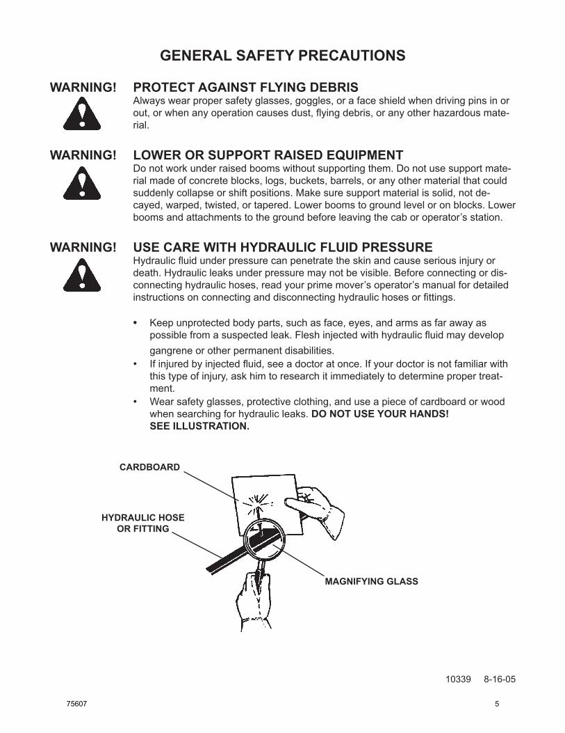
• Wear safety glasses, protective clothing, and use a piece of cardboard or wood when searching for hydraulic leaks. DO NOT USE YOUR HANDS!
SEE ILLUSTRATION.
CARDBOARD
HYDRAULIC HOSEOR FITTING
MAGNIFYING GLASS
10339 8-16-05
75607 5
GENERAL SAFETY PRECAUTIONS
10340 8-16-05
WARNING! DO NOT MODIFY MACHINE OR ATTACHMENTSModifications may weaken the integrity of the attachment and may impair the func-tion, safety, life, and performance of the attachment. When making repairs, use only the manufacturer’s genuine parts, following authorized instructions. Other parts may be substandard in fit and quality. Never modify any ROPS (Roll Over Protection Structure) or FOPS (Falling Object Protective Structure) equipment or device. Any modifications must be authorized in writing by the manufacturer.
WARNING! SAFELY MAINTAIN AND REPAIR EQUIPMENT• Do not wear loose clothing or any accessories that can catch in moving parts. If
you have long hair, cover or secure it so that it does not become entangled in the equipment.
• Work on a level surface in a well-lit area.• Use properly grounded electrical outlets and tools.• Use the correct tools for the job at hand. Make sure they are in good condition for
the task required.• Wear the protective equipment specified by the tool manufacturer.
SAFELY OPERATE EQUIPMENTDo not operate equipment until you are completely trained by a qualified operator in how to use the controls, know its capabilities, dimensions, and all safety require-ments. See your machine’s manual for these instructions.• Keep all step plates, grab bars, pedals, and controls free of dirt, grease, debris,
and oil.• Never allow anyone to be around the equipment when it is operating.• Do not allow riders on the attachment or the prime mover.• Do not operate the equipment from anywhere other than the correct operator’s
position. • Never leave equipment unattended with the engine running, or with this attach-
ment in a raised position.• Do not alter or remove any safety feature from the prime mover or this attach-
ment.• Know your work site safety rules as well as traffic rules and flow. When in doubt
on any safety issue, contact your supervisor or safety coordinator for an explana-tion.
6 75607
EQUIPMENT SAFETY PRECAUTIONSWARNING! KNOW WHERE UTILITIES ARE
Observe overhead electrical and other utility lines. Be sure equipment will clear them. When digging, call your local utilities for location of buried utility lines, gas, water, and sewer, as well as any other hazard you may encounter.
OPERATING THE BACKHOEBlock off work area from bystanders, livestock, etc. Allow plenty of room for backhoe swing.Operate only from the operator’s station.Use the backhoe only for digging. Do not use the backhoe to pull things, as a batter-ing ram, or attach ropes, chains etc., to the unit.Do not dig close to the stabilizers. The ground could collapse from under the back-hoe.Do not lift loads in excess of the capacity of the backhoe or prime mover.When operating on slopes, dig with the backhoe uphill, and avoid swinging the backhoe to the downhill side. Avoid steep hillside operation, which could cause the prime mover to overturn.Reduce speed when driving over rough terrain, on a slope, or turning, to avoid overturning the vehicle.Do not adjust relief valve settings. Incorrect valve settings could result in equipment damage and/or personal injury.An operator must not use drugs or alcohol, which can change his or her alertness or coordination. An operator taking prescription or over-the-counter drugs should seek medical advice on whether or not he or she can safely operate equipment.Before exiting the prime mover, lower the backhoe bucket and stabilizers to the ground, turn off the prime mover’s engine, remove the key and apply the brakes.
TRANSPORTING THE BACKHOEBe sure to engage boom and swing locks before transporting backhoe to prevent uncontrolled movement.When driving on public roads use safety lights, reflectors, Slow Moving Vehicle signs etc., to prevent accidents. Check local government regulations that may affect you.Do not drive close to ditches, excavations, etc., cave in could result.Do not smoke when refueling the prime mover. Allow room in the gas tank for expansion. Wipe up any spilled fuel. Secure cap tightly when done.
MAINTAINING THE BACKHOEBefore performing maintenance, lower the attachment to the ground, turn off the engine, remove the key and apply the brakes.Never perform any work on the attachment unless you are authorized and quali-fied to do so. Always read the operator service manual’s before any repair is made. After completing maintenance or repair, check for correct functioning of the backhoe. If not functioning properly, always tag “DO NOT OPERATE” until all problems are corrected.Worn, damaged, or illegible safety decals must be replaced. New safety decals can be ordered from BRADCO.Never make hydraulic repairs while the system is under pressure, or cylinders under load. Serious personal injury or death could result.Never work under a raised attachment.
•
••
•
••
•
•
•
•
•
•
••
•
•
•
•
• 10492 2-13-06
75607 7
DECALS
10709 7-7-10-2
DECAL PLACEMENT
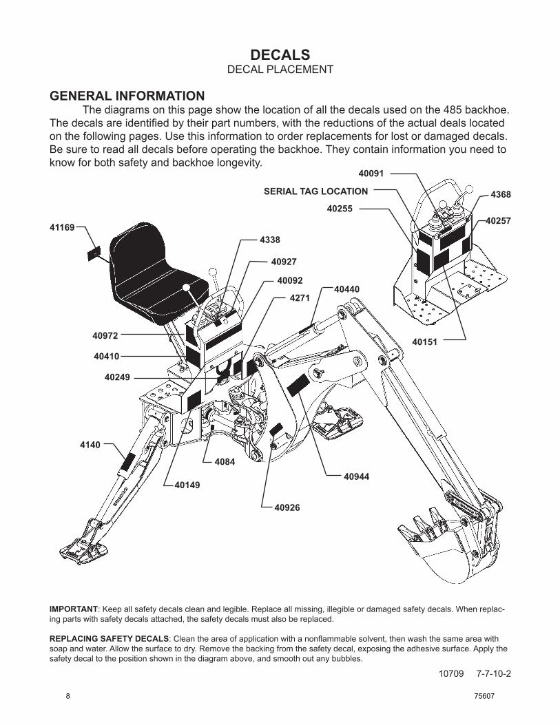
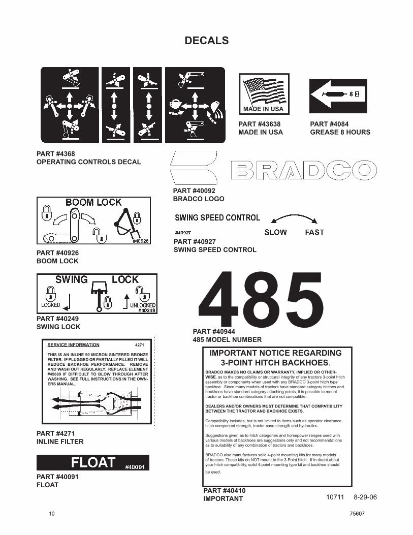
GENERAL INFORMATION The diagrams on this page show the location of all the decals used on the 485 backhoe. The decals are identified by their part numbers, with the reductions of the actual deals located on the following pages. Use this information to order replacements for lost or damaged decals. Be sure to read all decals before operating the backhoe. They contain information you need to know for both safety and backhoe longevity.
40091
40092
40149
40151
40249
4025540257
40440
408440944
40926
40927
4140
4271
4338
4368SERIAL TAG LOCATION
IMPORTANT: Keep all safety decals clean and legible. Replace all missing, illegible or damaged safety decals. When replac-ing parts with safety decals attached, the safety decals must also be replaced.
REPLACING SAFETY DECALS: Clean the area of application with a nonflammable solvent, then wash the same area with soap and water. Allow the surface to dry. Remove the backing from the safety decal, exposing the adhesive surface. Apply the safety decal to the position shown in the diagram above, and smooth out any bubbles.
40972
41169
40410
8 75607
DECALS
10710 7-6-10-2
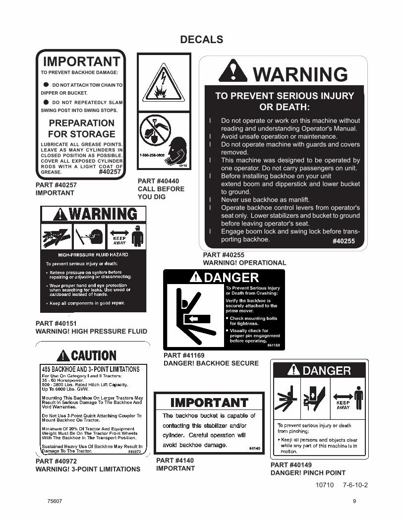
IMPORTANTTO PREVENT BACKHOE DAMAGE:
DO NOT ATTACH TOW CHAIN TO DIPPER OR BUCKET.
DO NOT REPEATEDLY SLAM SWING POST INTO SWING STOPS.
PREPARATIONFOR STORAGE
LUBRICATE ALL GREASE POINTS. LEAVE AS MANY CYLINDERS IN CLOSED POSITION AS POSSIBLE. COVER ALL EXPOSED CYLINDER RODS WITH A LIGHT COAT OF GREASE. #40257
PART #40257IMPORTANT
PART #40440CALL BEFORE YOU DIG
PART #4140IMPORTANT
PART #40151WARNING! HIGH PRESSURE FLUID
WARNINGTO PREVENT SERIOUS INJURY
OR DEATH:l Do not operate or work on this machine without
reading and understanding Operator's Manual.l Avoid unsafe operation or maintenance.l Do not operate machine with guards and covers
removed.l This machine was designed to be operated by
one operator. Do not carry passengers on unit.l Before installing backhoe on your unit extend boom and dipperstick and lower bucket
to ground.l Never use backhoe as manlift.l Operate backhoe control levers from operator's
seat only. Lower stabilizers and bucket to ground before leaving operator's seat.
l Engage boom lock and swing lock before trans-porting backhoe. #40255
PART #40255WARNING! OPERATIONAL
PART #40149DANGER! PINCH POINT
PART #40972WARNING! 3-POINT LIMITATIONS
PART #41169DANGER! BACKHOE SECURE
75607 9
DECALS
10711 8-29-06
MADE IN USA
SERVICE INFORMATION 4271
THIS IS AN INLINE 90 MICRON SINTERED BRONZE FILTER. IF PLUGGED OR PARTIALLY FILLED IT WILL REDUCE BACKHOE PERFORMANCE. REMOVE AND WASH OUT REGULARLY. REPLACE ELEMENT #45689 IF DIFFICULT TO BLOW THROUGH AFTER WASHING. SEE FULL INSTRUCTIONS IN THE OWN-ERS MANUAL.
485
PART #4368OPERATING CONTROLS DECAL
PART #40926BOOM LOCK
PART #40927SWING SPEED CONTROL
PART #40091FLOAT
PART #4084GREASE 8 HOURS
PART #43638MADE IN USA
PART #40249SWING LOCK PART #40944
485 MODEL NUMBER
PART #40092BRADCO LOGO
PART #4271INLINE FILTER
IMPORTANT NOTICE REGARDING 3-POINT HITCH BACKHOES.
BRADCO MAKES NO CLAIMS OR WARRANTY, IMPLIED OR OTHER-WISE, as to the compatibility or structural integrity of any tractors 3-point hitch assembly or components when used with any BRADCO 3-point hitch type backhoe. Since many models of tractors have standard category hitches and backhoes have standard category attaching points, it is possible to mount tractor or backhoe combinations that are not compatible.
DEALERS AND/OR OWNERS MUST DETERMINE THAT COMPATIBILITY BETWEEN THE TRACTOR AND BACKHOE EXISTS.
Compatibility includes, but is not limited to items such as operator clearance, hitch component strength, tractor case strength and hydraulics.
Suggestions given as to hitch categories and horsepower ranges used with various models of backhoes are suggestions only and not recommendations as to suitability of any combination of tractors and backhoes.
BRADCO also manufactures solid 4-point mounting kits for many models of tractors. These kits do NOT mount to the 3-Point hitch. If in doubt about your hitch compatibility, solid 4-point mounting type kit and backhoe should
pRepARINGtHebACkHOe-SeAtADJUStMeNt The backhoe seat can be adjusted to facilitate operator comfort and head clearance. There is a lever under the seat for sliding forward/backward, safety snap pins on the pedestal for positioning the seat up/down and also the pedestal can be moved forward on the console assembly. Before mount-ing the backhoe onto your loader/tractor move the seat forward and position it into the lowest position. After installation the seat may be moved back if clearance is not a factor.
bACkHOebUCketOptIONS Basic backhoes are shipped complete with bucket. However, several bucket options are avail-able for the backhoe. Refer to the table below for proper identification of backhoe bucket op-tions.
bUCketASSeMbLIeS 10” ............................ #81710 12” ............................ #81712 16” ............................ #81716 18” ............................ #81718 24” ........................... #81724 Additional buckets without teeth are available upon request.
75607 11
INSTALLATION
10720 8-30-06
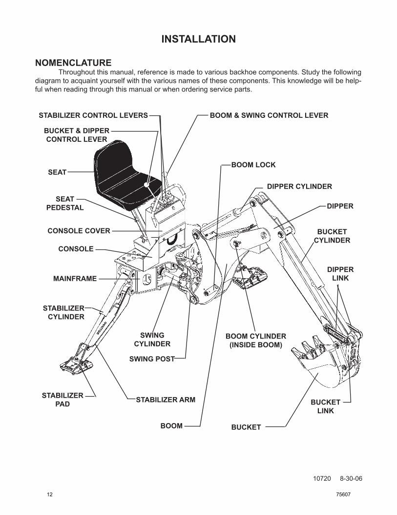
NOMeNCLAtURe Throughout this manual, reference is made to various backhoe components. Study the following diagram to acquaint yourself with the various names of these components. This knowledge will be help-ful when reading through this manual or when ordering service parts.
StAbILIZeRCYLINDeR
StAbILIZeRARM
SWING POST
SWINGCYLINDeR
StAbILIZeRpAD
bOOM bUCket
bOOMCYLINDeR(INSIDebOOM)
bUCketLINk
DIppeRCYLINDeR
bOOMLOCk
DIppeRLINk
bUCketCYLINDeR
DIppeR
bOOM&SWINGCONtROLLeVeRStAbILIZeRCONtROLLeVeRS
bUCket&DIppeRCONtROLLeVeR
SEAT
CONSOLeCOVeR
CONSOLE
MAINFRAME
SEAT peDeStAL
12 75607
INSTALLATION
10725 9-7-06
MOUNTING KITS The three point hitch adapter kit will adapt the backhoe to any three point hitch tractor and therefore this kit will be covered in this manual to help facilitate mounting onto any tractor’s three point hitch system. Due to the various models of skid loaders that this backhoe is designed for, installation instructions for the mounting kit you have received and the backhoe itself is covered in a sepa-rate set of instructions that will address your particular combination.
IMPORTANT NOTICE REGARDING 3-POINT HITCH BACKHOES
BRADCO makes no claims or warranty, implied or otherwise, as to the compatibility or structural integrity of any tractors 3-point hitch assembly or components when used with any BRADCO 3-point type backhoe. Since many models of tractors have standard category hitches and backhoes have standard category attaching points, it is possible to mount tractor or backhoe combinations that are not compatible.
DEALERS AND/OR OWNERS MUST DETERMINE THAT COMPATIBILITY BETWEEN THE TRACTOR AND BACKHOE EXISTS.
Compatibility includes, but is not limited to items such as operator clearance, hitch component strength, tractor case strength and hydraulics.
Suggestions given as to hitch categories and horsepower ranges used with various models of backhoes are suggestions only and not recommendations as to suitability of any combination of tractors and backhoes.
BRADCO also manufactures solid 4-point mounting kits for many models of tractors. These kits do NOT mount to the 3-point hitch. If in doubt about your hitch compatibility, a solid 4-point mounting type kit and backhoe should be used.
NOTICE! Sustained heavy use of this backhoe may result in damage to your tractor.
NOTICE! The 485 backhoe is designed for use on category I and II tractors with45-60 horse power, 800-3800 lbs. rated hitch lift capacity and up to 6000 lbs GVW. Mounting this backhoe on larger tractors may result in serious damage to the backhoe and void warranties.
WARNING! Only use on Category I and Category II tractors. Do not use 3-point quick attaching coupler to mount backhoe onto tractor. Minimum of 20% of the tractor and equipment weight must be on the tractor
front wheels with the backhoe in the transport position. DonotexceedROPScertificationweight. Backhoe digging forces can lift and turn tractor over. Make sure stabilizer
padsareonfirmgroundandavoidsteepbanks.
75607 13
INSTALLATION
10726 9-7-06
Before you install a 3-point hitch backhoe on any tractor there are certain critical points that must be checked. Failure to address these points could result in serious damage to the equipment, and serious injury or even death to the operator. Do NOT attempt to install the backhoe until you have gone through the following points and made any corrections to the equipment that might be deemed necessary.
PRELIMINARY CLEARANCE CHECK
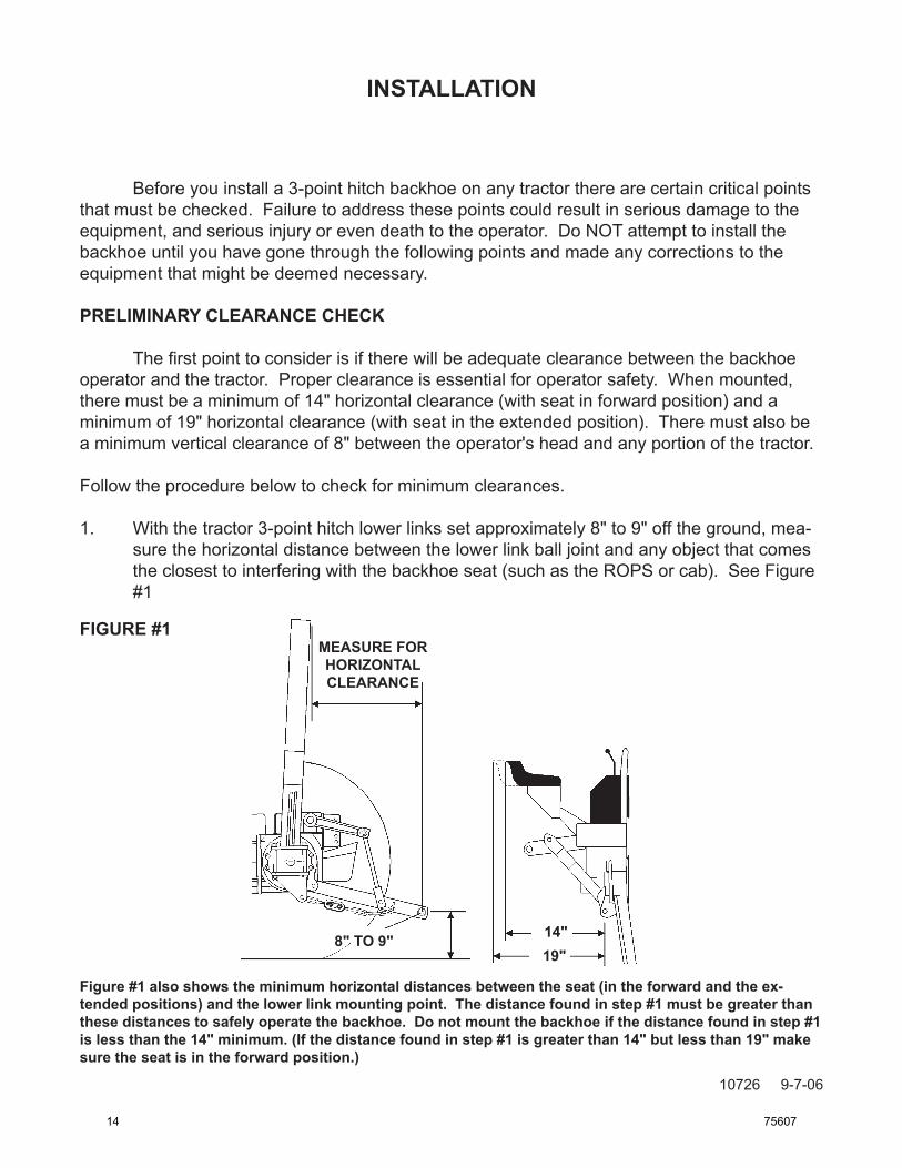
Thefirstpointtoconsiderisiftherewillbeadequateclearancebetweenthebackhoeoperator and the tractor. Proper clearance is essential for operator safety. When mounted, there must be a minimum of 14" horizontal clearance (with seat in forward position) and a minimum of 19" horizontal clearance (with seat in the extended position). There must also be a minimum vertical clearance of 8" between the operator's head and any portion of the tractor.
Follow the procedure below to check for minimum clearances.
1. With the tractor 3-point hitch lower links set approximately 8" to 9" off the ground, mea-sure the horizontal distance between the lower link ball joint and any object that comes the closest to interfering with the backhoe seat (such as the ROPS or cab). See Figure #1
FIGURE #1
Figure #1 also shows the minimum horizontal distances between the seat (in the forward and the ex-tended positions) and the lower link mounting point. The distance found in step #1 must be greater than these distances to safely operate the backhoe. Do not mount the backhoe if the distance found in step #1 is less than the 14" minimum. (If the distance found in step #1 is greater than 14" but less than 19" make sure the seat is in the forward position.)
MEASURE FOR HORIZONTALCLEARANCE
8" TO 9" 14"19"
14 75607
INSTALLATION
10727 9-7-06
MEASURE FOR VERTICAL CLEARANCE
8" TO 9"
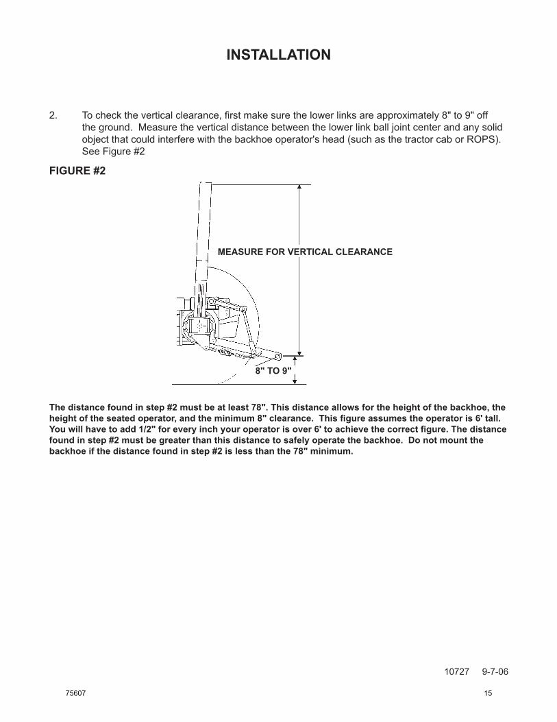
2. Tochecktheverticalclearance,firstmakesurethelowerlinksareapproximately8"to9"offthe ground. Measure the vertical distance between the lower link ball joint center and any solid object that could interfere with the backhoe operator's head (such as the tractor cab or ROPS). See Figure #2
FIGURE #2
The distance found in step #2 must be at least 78". This distance allows for the height of the backhoe, the heightoftheseatedoperator,andtheminimum8"clearance.Thisfigureassumestheoperatoris6'tall.Youwillhavetoadd1/2"foreveryinchyouroperatorisover6'toachievethecorrectfigure.Thedistancefound in step #2 must be greater than this distance to safely operate the backhoe. Do not mount the backhoe if the distance found in step #2 is less than the 78" minimum.
75607 15
INSTALLATION
10721 8-30-06
3-POINT HITCH ADAPTER KIT
GENERAL INFORMATION The following instructions will help you to mount your backhoe onto a Category I and II three-point hitch system. Remember to read all safety warnings, decals, and operating instruc-tions before operating the tractor or backhoe.
WARNING! Three point hitch backhoes used on tractors equipped with either ROPS or cabs can be dangerous and may cause injury or death if not properly in-stalled, operated and maintained.
Always read the operator's manual. Always maintain an 8" clearance between the operator and the cab or
ROPS. Always use pins of the proper size and grade at the 3-point hitch points.
MOUNTING INSTRUCTIONS
1. Remove the top link from the tractor.
2. If the tractor is equipped with draft control, render it inoperable. If this is not possible, adjust the draft lever to its heaviest load position.
3. Remove the steel shipping banding from around the backhoe and skid.
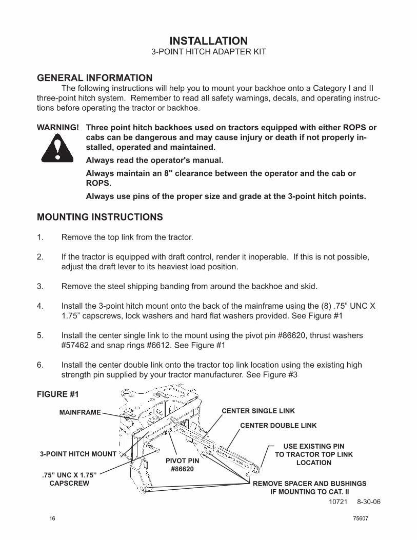
4. Install the 3-point hitch mount onto the back of the mainframe using the (8) .75” UNC X 1.75” capscrews, lock washers and hard flat washers provided. See Figure #1
5. Install the center single link to the mount using the pivot pin #86620, thrust washers #57462 and snap rings #6612. See Figure #1
6. Install the center double link onto the tractor top link location using the existing high strength pin supplied by your tractor manufacturer. See Figure #3
FIGURE #1
3-POINT hITCh MOUNT
.75” UNC x 1.75” CAPSCREW
CENTER SINGLE LINk
CENTER dOUbLE LINk
USE ExISTING PINTO TRACTOR TOP LINk
LOCATION
REMOvE SPACER ANd bUShINGS IF MOUNTING TO CAT. II
MAINFRAME
PIvOT PIN #86620
16 75607
INSTALLATION
10722 9-5-06
3-POINT HITCH ADAPTER KIT
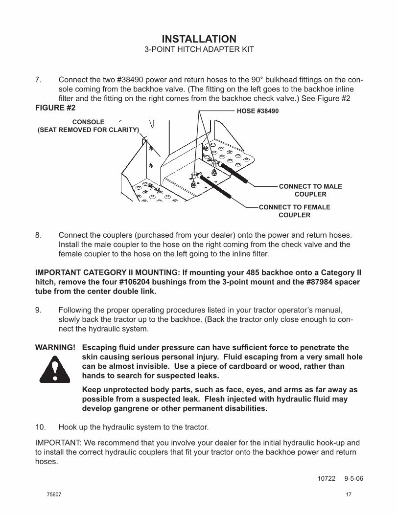
7. Connect the two #38490 power and return hoses to the 90° bulkhead fittings on the con-sole coming from the backhoe valve. (The fitting on the left goes to the backhoe inline filter and the fitting on the right comes from the backhoe check valve.) See Figure #2
FIGURE #2
8. Connect the couplers (purchased from your dealer) onto the power and return hoses. Install the male coupler to the hose on the right coming from the check valve and the female coupler to the hose on the left going to the inline filter.
IMPORTANT CATEGORY II MOUNTING: If mounting your 485 backhoe onto a Category II hitch, remove the four #106204 bushings from the 3-point mount and the #87984 spacer tube from the center double link.
9. Following the proper operating procedures listed in your tractor operator’s manual, slowly back the tractor up to the backhoe. (Back the tractor only close enough to con-nect the hydraulic system.
WARNING! Escapingfluidunderpressurecanhavesufficientforcetopenetratetheskin causing serious personal injury. Fluid escaping from a very small hole can be almost invisible. Use a piece of cardboard or wood, rather than hands to search for suspected leaks.
keep unprotected body parts, such as face, eyes, and arms as far away as possiblefromasuspectedleak.Fleshinjectedwithhydraulicfluidmaydevelop gangrene or other permanent disabilities.
10. Hook up the hydraulic system to the tractor.
IMPORTANT: We recommend that you involve your dealer for the initial hydraulic hook-up and to install the correct hydraulic couplers that fit your tractor onto the backhoe power and return hoses.
hOSE #38490CONSOLE
(SEAT REMOvEd FOR CLARITY)
CONNECT TO MALE COUPLER
CONNECT TO FEMALE COUPLER
75607 17
INSTALLATION3-POINT HITCH ADAPTER KIT
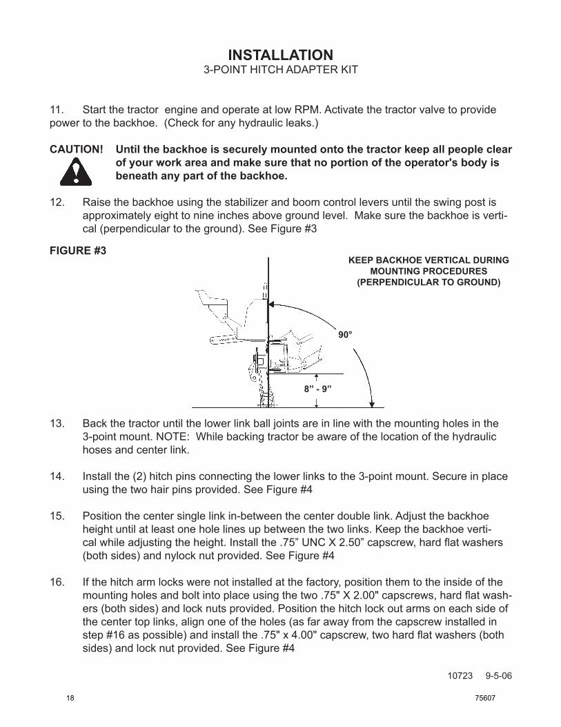
11. Start the tractor engine and operate at low RPM. Activate the tractor valve to provide power to the backhoe. (Check for any hydraulic leaks.)
CAUTION! Until the backhoe is securely mounted onto the tractor keep all people clear of your work area and make sure that no portion of the operator's body is beneath any part of the backhoe.
12. Raise the backhoe using the stabilizer and boom control levers until the swing post is approximately eight to nine inches above ground level. Make sure the backhoe is verti-cal (perpendicular to the ground). See Figure #3
FIGURE #3
13. Back the tractor until the lower link ball joints are in line with the mounting holes in the 3-point mount. NOTE: While backing tractor be aware of the location of the hydraulic hoses and center link.
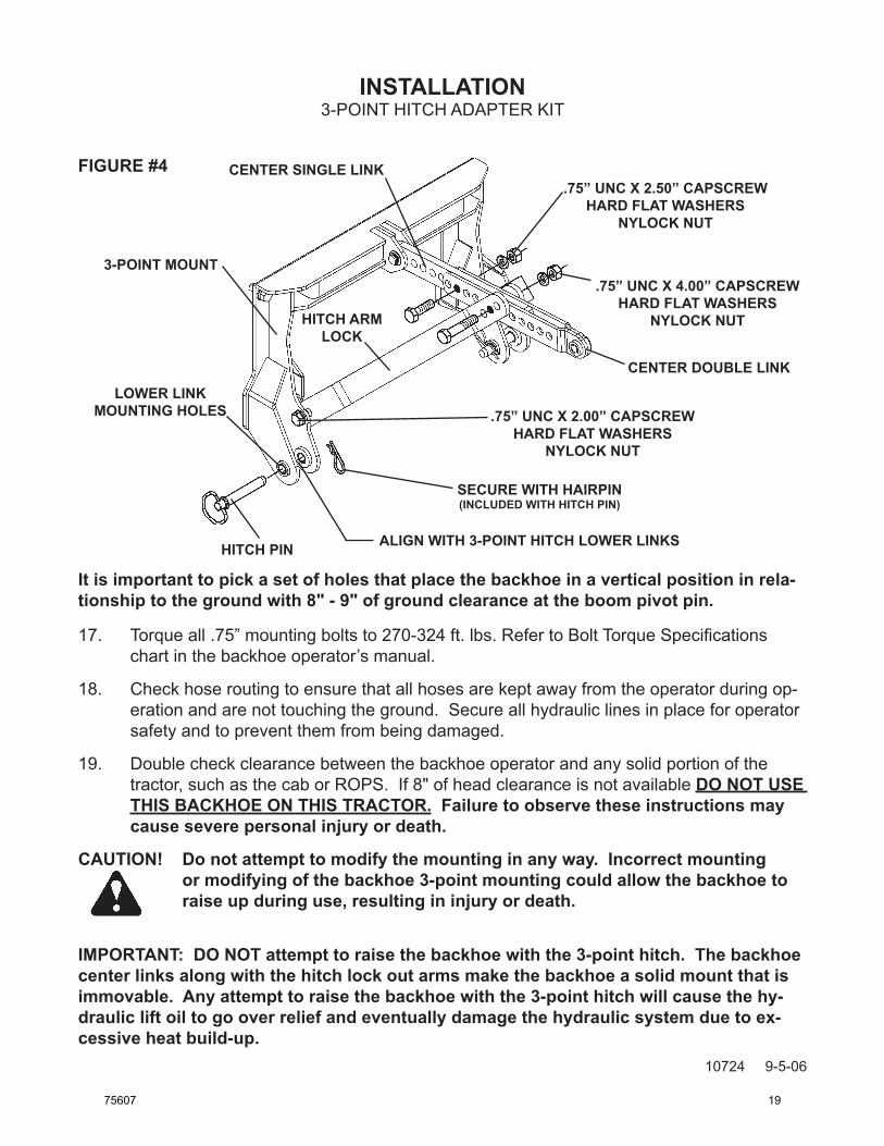
14. Install the (2) hitch pins connecting the lower links to the 3-point mount. Secure in place using the two hair pins provided. See Figure #4
15. Position the center single link in-between the center double link. Adjust the backhoe height until at least one hole lines up between the two links. Keep the backhoe verti-cal while adjusting the height. Install the .75” UNC X 2.50” capscrew, hard flat washers (both sides) and nylock nut provided. See Figure #4
16. If the hitch arm locks were not installed at the factory, position them to the inside of the mounting holes and bolt into place using the two .75" X 2.00" capscrews, hard flat wash-ers (both sides) and lock nuts provided. Position the hitch lock out arms on each side of the center top links, align one of the holes (as far away from the capscrew installed in step #16 as possible) and install the .75" x 4.00" capscrew, two hard flat washers (both sides) and lock nut provided. See Figure #4
90°
8” - 9”
kEEP bACkhOE vERTICAL dURING MOUNTING PROCEdURES
(PERPENdICULAR TO GROUNd)
10723 9-5-06
18 75607
INSTALLATION3-POINT HITCH ADAPTER KIT
FIGURE #4
It is important to pick a set of holes that place the backhoe in a vertical position in rela-tionship to the ground with 8" - 9" of ground clearance at the boom pivot pin.
17. Torque all .75” mounting bolts to 270-324 ft. lbs. Refer to Bolt Torque Specifications chart in the backhoe operator’s manual.
18. Check hose routing to ensure that all hoses are kept away from the operator during op-eration and are not touching the ground. Secure all hydraulic lines in place for operator safety and to prevent them from being damaged.
19. Double check clearance between the backhoe operator and any solid portion of the tractor, such as the cab or ROPS. If 8" of head clearance is not available dO NOT USE ThIS bACkhOE ON ThIS TRACTOR. Failure to observe these instructions may cause severe personal injury or death.
CAUTION! do not attempt to modify the mounting in any way. Incorrect mounting or modifying of the backhoe 3-point mounting could allow the backhoe to raise up during use, resulting in injury or death.
IMPORTANT: dO NOT attempt to raise the backhoe with the 3-point hitch. The backhoe center links along with the hitch lock out arms make the backhoe a solid mount that is immovable. Any attempt to raise the backhoe with the 3-point hitch will cause the hy-draulic lift oil to go over relief and eventually damage the hydraulic system due to ex-cessive heat build-up.
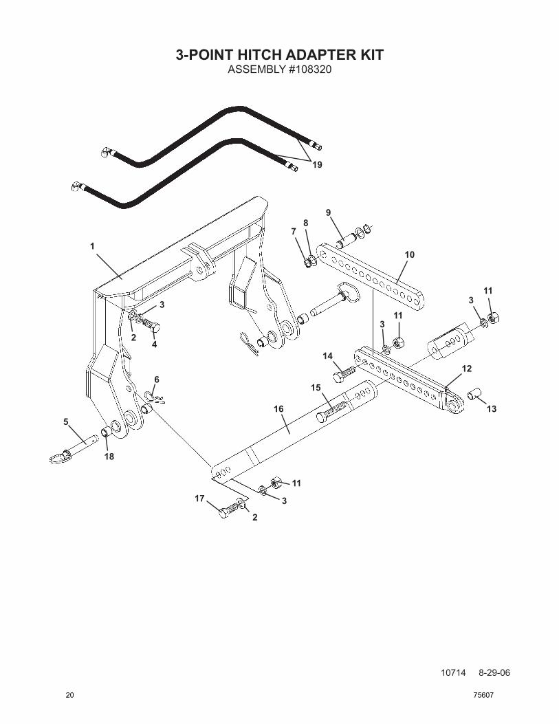
6 - 1985 Hair Pin - Cat. I Hitch - 1991 Hair Pin - Cat. II 7 2 6612 Snap Ring 8 2 57462 Thrust Washer 9 1 86620 Pivot Pin 10 1 107101 Single Link
11 4 1534 .75” UNC Lock Nut 12 1 107548 Double Link 13 1 87984 Spacer Tube (Remove for Cat. II Hitch) 14 1 1141 .75” UNC X 2.50” Hex Capscrew 15 1 1147 .75” UNC X 4.00” Hex Capscrew
16 2 107549 Hitch Arm Lock 17 2 1139 .75” UNC X 2.00” Hex Capscrew 18 4 106204 Bushing (Remove for Cat. II Hitch) 19 2 38490 Hose .50” X 40” 8MBo-8FJX 90°
ASSEMBLY #108320
75607 21
OPERATING INSTRUCTIONS
7831 8-10-06-2
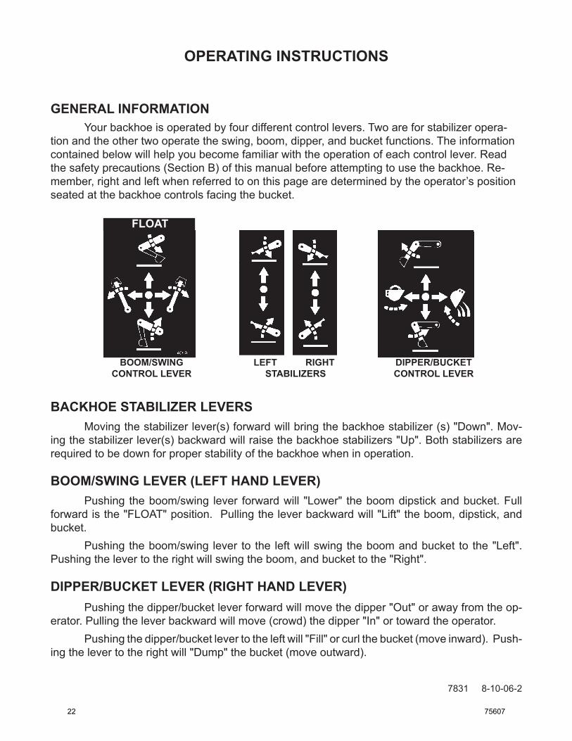
GENERAL INFORMATION Your backhoe is operated by four different control levers. Two are for stabilizer opera-tion and the other two operate the swing, boom, dipper, and bucket functions. The information contained below will help you become familiar with the operation of each control lever. Read the safety precautions (Section B) of this manual before attempting to use the backhoe. Re-member, right and left when referred to on this page are determined by the operator’s position seated at the backhoe controls facing the bucket.
BACKHOE STABILIZER LEVERS Moving the stabilizer lever(s) forward will bring the backhoe stabilizer (s) "Down". Mov-ing the stabilizer lever(s) backward will raise the backhoe stabilizers "Up". Both stabilizers are required to be down for proper stability of the backhoe when in operation.
BOOM/SWING LEVER (LEFT HAND LEVER) Pushing the boom/swing lever forward will "Lower" the boom dipstick and bucket. Full forward is the "FLOAT" position. Pulling the lever backward will "Lift" the boom, dipstick, and bucket. Pushing the boom/swing lever to the left will swing the boom and bucket to the "Left". Pushing the lever to the right will swing the boom, and bucket to the "Right".
DIPPER/BUCKET LEVER (RIGHT HAND LEVER) Pushing the dipper/bucket lever forward will move the dipper "Out" or away from the op-erator. Pulling the lever backward will move (crowd) the dipper "In" or toward the operator. Pushing the dipper/bucket lever to the left will "Fill" or curl the bucket (move inward). Push-ing the lever to the right will "Dump" the bucket (move outward).
BOOM/SWING LEFT RIGHT DIPPER/BUCKET CONTROL LEVER STABILIZERS CONTROL LEVER
FLOAT
22 75607
OPERATING INSTRUCTIONS
6758 1-25-06-2
OPERATING TECHNIQUESATTACHMENT TYPE BACKHOES
GENERAL INFORMATION
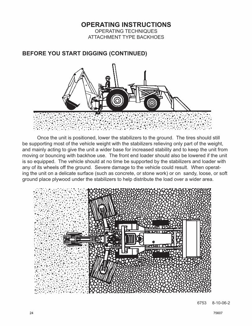
When operating the backhoe, smoothness of technique should be strived for at all times. Smoothness will come with experience and practice at feathering the controls. Estab-lish a flowing digging cycle to increase operator efficiency and save unnecessary wear on the machine.
Observe the following points to obtain the best results and to fully utilize the digging force of the backhoe.
WARNING! Operate the backhoe only when seated at the controls. Any other method could result in serious personal injury or death.
Never attempt to drive the tractor when seated at the backhoe controls.
Check the prospective digging area for hidden utility lines before operating the backhoe or when in doubt of their location, contact the local utility com-panies. When operating the backhoe in an area where utilities are expected to be present, throttle the backhoe down and proceed with caution. If you feel the backhoe bucket made contact with anything out of the ordinary, stop digging at once. Have the obstruction checked by hand. If a utility line has been damaged, contact the affected utility at once.
BEFORE YOU START DIGGING
Before any excavating is started, it is always a good idea to plan out the job first. Vari-ous things need to be considered and taken into account prior to the actual digging. The operator should inspect the job site and take notice of any potential hazards in the area. He should have a complete understanding of the tasks he is expected to perform. Figure out what will be done with the spoil (excavated soil), will it be used to backfill or be trucked out? What are the soil conditions like? Will you have to work around others? Etc.
Once you have become familiar with the job site and understand the job require-ments, it is time to set up for the actual digging. Position the backhoe in such a way as to minimize repositioning the unit and to maximize digging efficiency. Consider the placement of spoil and position the backhoe to be able to dig the maximum amount of soil, accurately, while leaving enough room for the spoil removed to be piled in the desired area.
75607 23
6753 8-10-06-2
OPERATING INSTRUCTIONSOPERATING TECHNIQUES
ATTACHMENT TYPE BACKHOES
BEFORE YOU START DIGGING (CONTINUED)
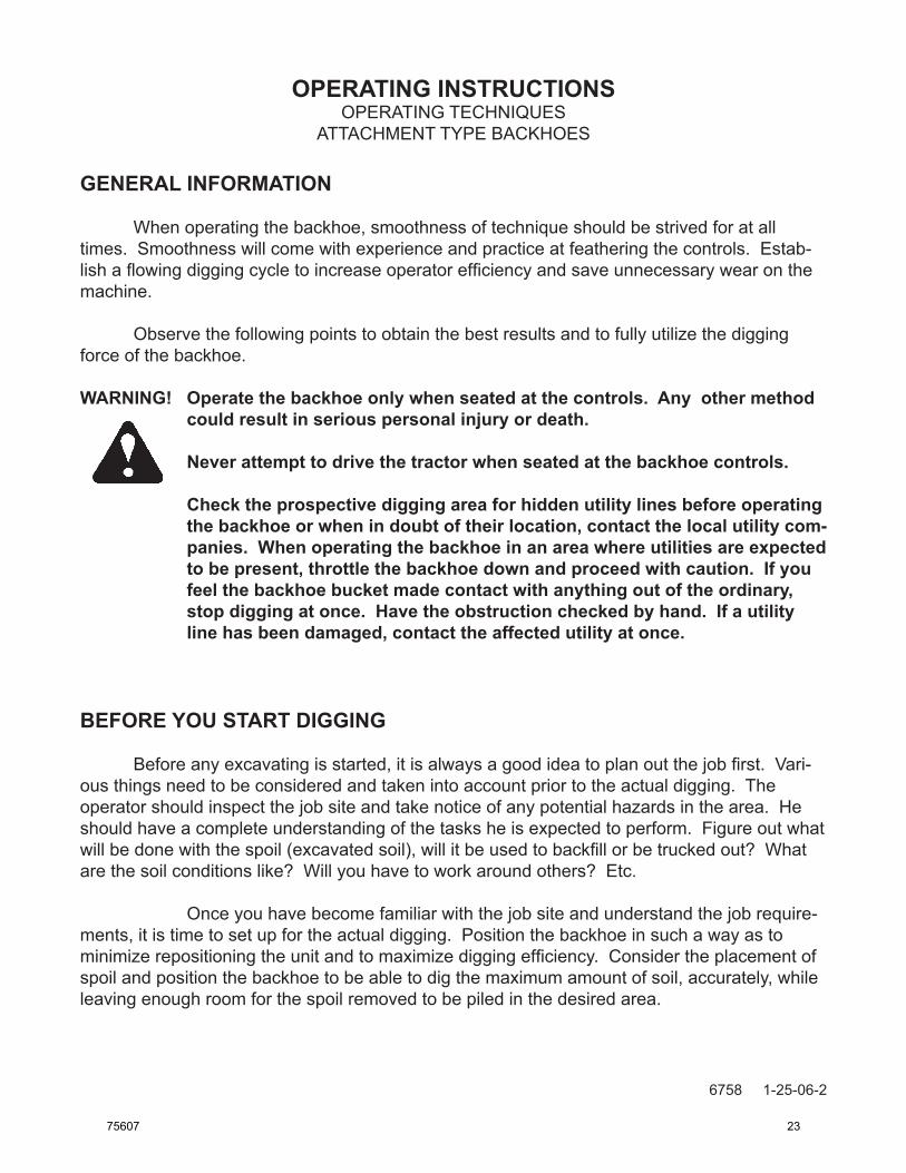
Once the unit is positioned, lower the stabilizers to the ground. The tires should still be supporting most of the vehicle weight with the stabilizers relieving only part of the weight, and mainly acting to give the unit a wider base for increased stability and to keep the unit from moving or bouncing with backhoe use. The front end loader should also be lowered if the unit is so equipped. The vehicle should at no time be supported by the stabilizers and loader with any of its wheels off the ground. Severe damage to the vehicle could result. When operat-ing the unit on a delicate surface (such as concrete, or stone work) or on sandy, loose, or soft ground place plywood under the stabilizers to help distribute the load over a wider area.
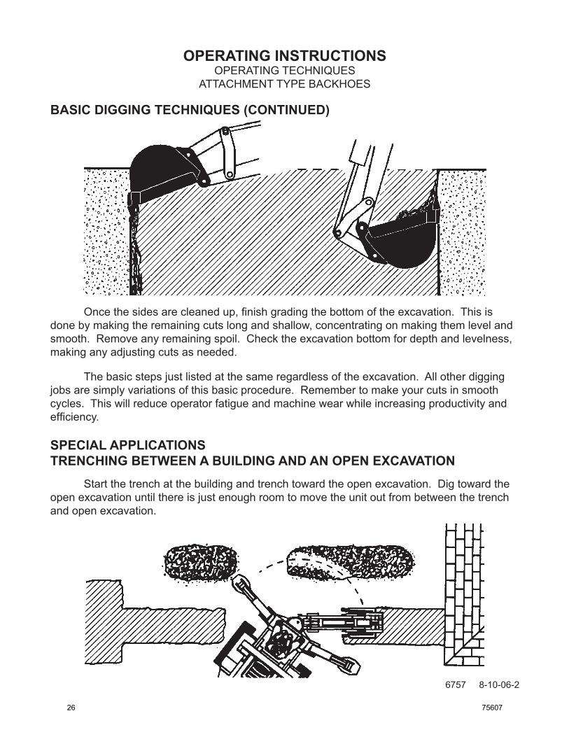
SPECIAL APPLICATIONSTRENCHING BETWEEN A BUILDING AND AN OPEN EXCAVATION Startthetrenchatthebuildingandtrenchtowardtheopenexcavation.Digtowardtheopenexcavationuntilthereisjustenoughroomtomovetheunitoutfrombetweenthetrenchandopenexcavation.
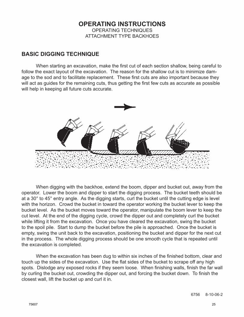
BASIC DIGGING TECHNIQUES (CONTINUED)
26 75607
OPERATING INSTRUCTIONS
3991 1-25-06-4
OPERATING TECHNIQUESATTACHMENT TYPE BACKHOES
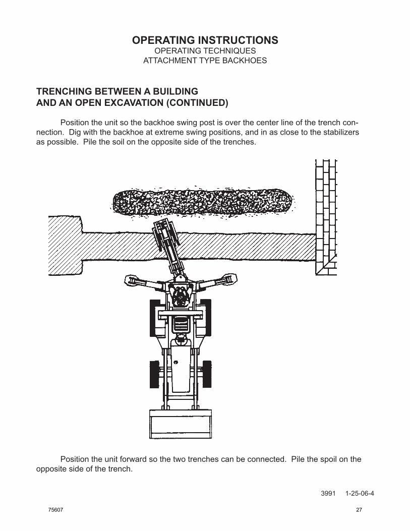
TRENCHING BETWEEN A BUILDINGAND AN OPEN EXCAVATION (CONTINUED)
Position the unit so the backhoe swing post is over the center line of the trench con-nection. Dig with the backhoe at extreme swing positions, and in as close to the stabilizers as possible. Pile the soil on the opposite side of the trenches.
Position the unit forward so the two trenches can be connected. Pile the spoil on the opposite side of the trench.
75607 27
OPERATING INSTRUCTIONS
6754 8-10-06-2
OPERATING TECHNIQUESATTACHMENT TYPE BACKHOES
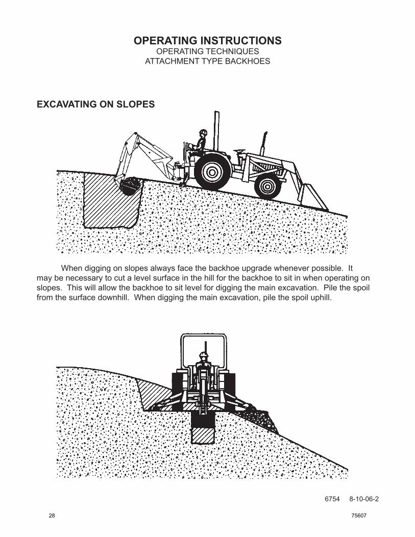
EXCAVATING ON SLOPES
When digging on slopes always face the backhoe upgrade whenever possible. It may be necessary to cut a level surface in the hill for the backhoe to sit in when operating on slopes. This will allow the backhoe to sit level for digging the main excavation. Pile the spoil from the surface downhill. When digging the main excavation, pile the spoil uphill.
28 75607
OPERATING INSTRUCTIONS
6755 8-10-06-2
OPERATING TECHNIQUESATTACHMENT TYPE BACKHOES
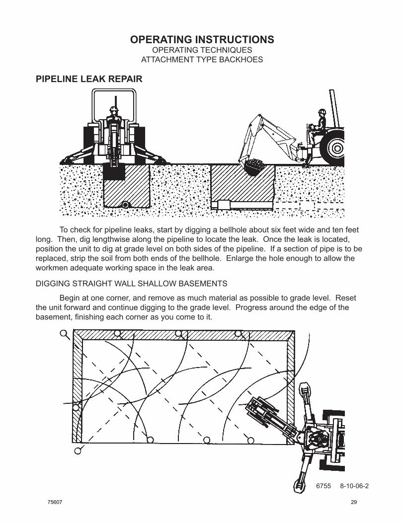
To check for pipeline leaks, start by digging a bellhole about six feet wide and ten feet long. Then, dig lengthwise along the pipeline to locate the leak. Once the leak is located, position the unit to dig at grade level on both sides of the pipeline. If a section of pipe is to be replaced, strip the soil from both ends of the bellhole. Enlarge the hole enough to allow the workmen adequate working space in the leak area.
DIGGING STRAIGHT WALL SHALLOW BASEMENTS
Begin at one corner, and remove as much material as possible to grade level. Reset the unit forward and continue digging to the grade level. Progress around the edge of the basement, finishing each corner as you come to it.
PIPELINE LEAK REPAIR
75607 29
OPERATING INSTRUCTIONS
3994 1-25-06-4
OPERATING TECHNIQUESATTACHMENT TYPE BACKHOES
MISCELLANEOUS - BACKFILLING To backfill an excavation, lower the extended bucket into the spoil pile. Curl the bucket and lift it clear of the spoil pile. Swing the bucket to the excavation and extend the bucket. Re-turn the bucket to the spoil pile and continue the cycle until the job is completed.
IMPORTANT: Do not backfill by using the swing circuit and dragging the bucket side-ways. Doing so could cause damage to the dipper, boom, and swing cylinders or main-frame.
IMPORTANT: Avoid constant jarring or hammering contact between the spoil pile and the loaded bucket as this may cause premature wear to the backhoe pins and bushings.
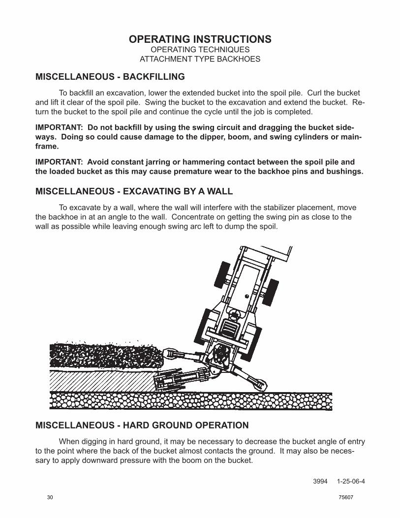
MISCELLANEOUS - EXCAVATING BY A WALL To excavate by a wall, where the wall will interfere with the stabilizer placement, move the backhoe in at an angle to the wall. Concentrate on getting the swing pin as close to the wall as possible while leaving enough swing arc left to dump the spoil.
MISCELLANEOUS - HARD GROUND OPERATION When digging in hard ground, it may be necessary to decrease the bucket angle of entry to the point where the back of the bucket almost contacts the ground. It may also be neces-sary to apply downward pressure with the boom on the bucket.
30 75607
OPERATING INSTRUCTIONS
10730 9-5-06
TRANSPORTING
GENERAL INFORMATION
Follow the simple steps listed below when preparing the backhoe for transportation between work sites. Read and follow the safety precautions for backhoe transporting listed in safety section of this manual before moving the backhoe.
1. Before transporting the backhoe, raise the boom, dipper, and bucket to the transporting position.
2. Install the swing lock pin.
3. Engage the boom lock by moving the boom lock handle to the left/down therefore lock-ing the boom to the swing post in the transporting position.
4. Raise all stabilizers.
CAUTION! Be sure to install a SMV (Slow Moving Vehicle) sign on the backhoe dipper before attempting to transport the backhoe.
When transporting the backhoe on a road or highway at night or during the day, use accessory lights and devices for adequate warning to the operators of other vehicles. In this regard, check local government regulations.
Always drive slowly over uneven terrain to avoid tipping the backhoe.
REmOvING fROm STORAGEWashoffalldirtandgrimefromtheunit.Thiswillassistyouinmakingavisualinspectionandhelpavoidoverlookinganywornordamagedcomponents.Checkallhydraulichosesandfittingsfordamagebeforeinstallingthebackhoeontoyourpowerunit.(Checkforleaksafterthebackhoehasbeenproperlyinstalled.)Checkalllubricationpointstoensurethereissufficientgreaseforsmoothoperation.Checkallboltsfortightness.
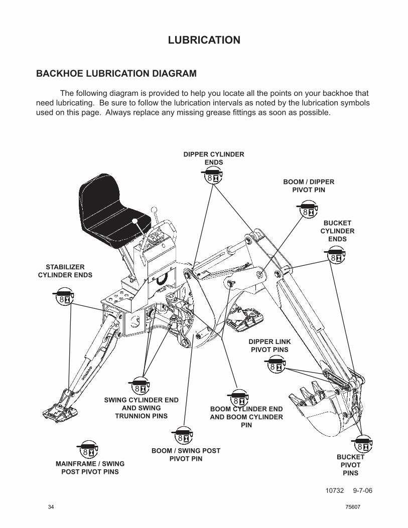
IMPORTANT: Avoid excessive greasing. Dirt collects on exposed grease and greatly increases wear. After greasing, wipe off excessive grease from fittings.
GENErAL INFOrMATION Regular maintenance is the key to long equipment life and safe operation. Maintenance requirements have been reduced to an absolute minimum. However, it is very important that these maintenance functions be performed as described below.
EvErY 8 HOUrs OF OPErATION Grease all swivel points (ram and base end of all cylinders) thoroughly. Excessive wear and even mechanical damage to pins and cylinders can result from inadequate lubrication. Use a multi-purpose grease. Lubricateallgreasefittingswithamulti-purposegrease.Forgreaselocations,refertothe diagram in the lubrication section of this manual.
EvErY 40 HOUrs OF OPErATION Checkhydraulicreservoirfluidlevel.Ifoilislow,checkalllines,fittings,andcontrolvalve for signs of leakage.
IMPORTANT: Hydraulic fluid level should be checked with backhoe in transport posi-tion.
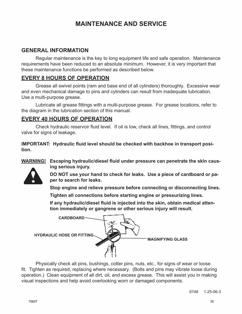
WArNING! Escaping hydraulic/diesel fluid under pressure can penetrate the skin caus-ing serious injury.
DO NOT use your hand to check for leaks. Use a piece of cardboard or pa-per to search for leaks.
Stop engine and relieve pressure before connecting or disconnecting lines. Tighten all connections before starting engine or pressurizing lines. If any hydraulic/diesel fluid is injected into the skin, obtain medical atten-
tion immediately or gangrene or other serious injury will result.
Physically check all pins, bushings, cotter pins, nuts, etc., for signs of wear or loose fit.Tightenasrequired,replacingwherenecessary.(Boltsandpinsmayvibratelooseduringoperation.)Cleanequipmentofalldirt,oil,andexcessgrease.Thiswillassistyouinmakingvisual inspections and help avoid overlooking worn or damaged components.
CArdBOArd
HYdrAULIC HOsE Or FITTINGMAGNIFYING GLAss
75607 35
MAINTENANCE ANd sErvICE
10729 9-7-06
TOOTH
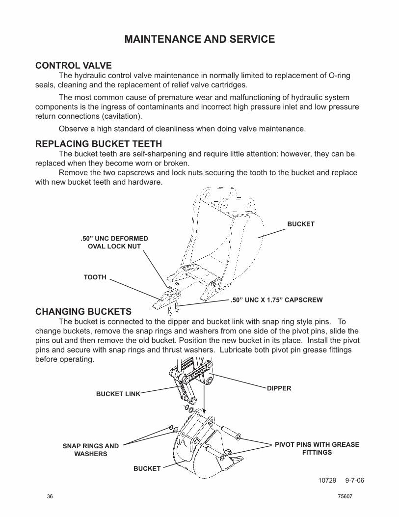
BUCKET
BUCKET
PIvOT PINs WITH GrEAsE FITTINGs
CONTrOL vALvE The hydraulic control valve maintenance in normally limited to replacement of O-ring seals, cleaning and the replacement of relief valve cartridges. The most common cause of premature wear and malfunctioning of hydraulic system components is the ingress of contaminants and incorrect high pressure inlet and low pressure return connections (cavitation). Observe a high standard of cleanliness when doing valve maintenance.
rEPLACING BUCKET TEETH The bucket teeth are self-sharpening and require little attention: however, they can be replaced when they become worn or broken. Remove the two capscrews and lock nuts securing the tooth to the bucket and replace with new bucket teeth and hardware.
.50” UNC dEFOrMEd OvAL LOCK NUT
CHANGING BUCKETs The bucket is connected to the dipper and bucket link with snap ring style pins. To change buckets, remove the snap rings and washers from one side of the pivot pins, slide the pins out and then remove the old bucket. Position the new bucket in its place. Install the pivot pins and secure with snap rings and thrust washers. Lubricate both pivot pin grease fittings before operating.
dIPPErBUCKET LINK
sNAP rINGs ANd WAsHErs
.50” UNC X 1.75” CAPsCrEW
36 75607
MAINTENANCE ANd sErvICE
10733 9-7-06
HOSE ROUTING
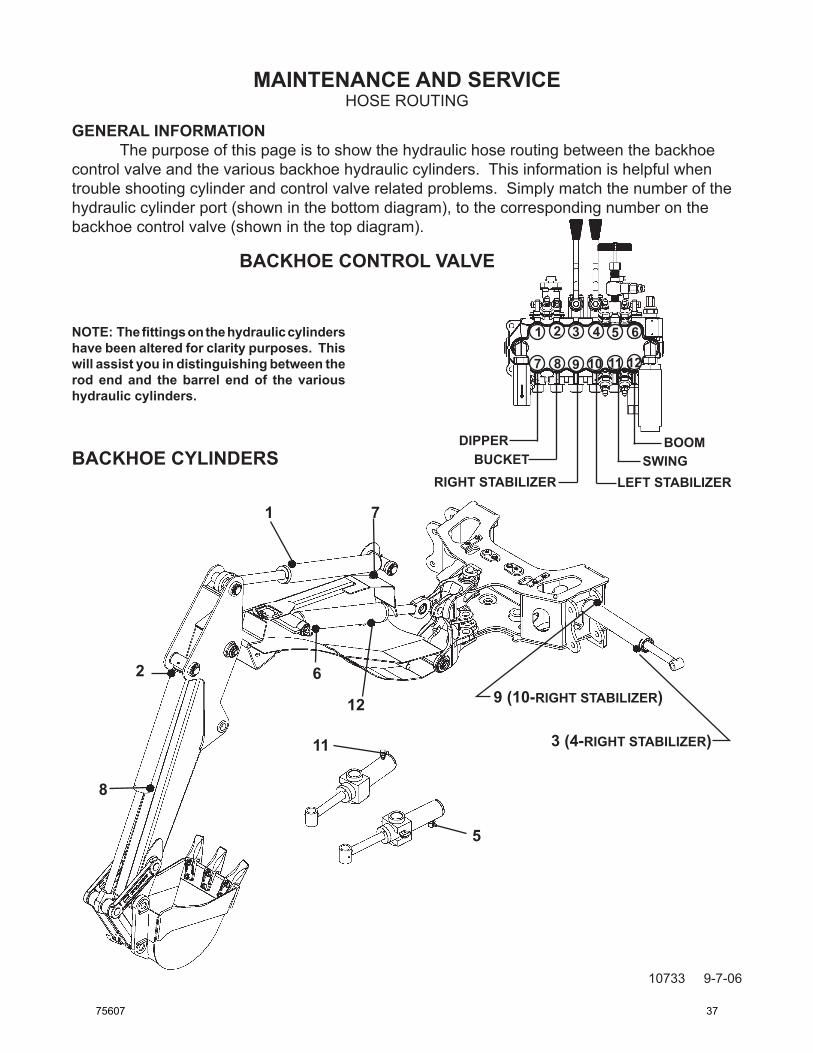
GENErAL INFOrMATION The purpose of this page is to show the hydraulic hose routing between the backhoe control valve and the various backhoe hydraulic cylinders. This information is helpful when trouble shooting cylinder and control valve related problems. Simply match the number of the hydraulic cylinder port (shown in the bottom diagram), to the corresponding number on the backhoe control valve (shown in the top diagram).
NOTE: The fittings on the hydraulic cylinders have been altered for clarity purposes. This will assist you in distinguishing between the rod end and the barrel end of the various hydraulic cylinders.
1 7
6
12
5
11
8
3 (4-rIGHT sTABILIZEr)
9 (10-rIGHT sTABILIZEr)
BACKHOE CONTrOL vALvE
2
BACKHOE CYLINdErsdIPPEr
BUCKET sWINGBOOM
rIGHT sTABILIZEr LEFT sTABILIZEr
1 2 3 4 5
121110987
6
75607 37
MAINTENANCE AND SERVICE
10530 3-8-06
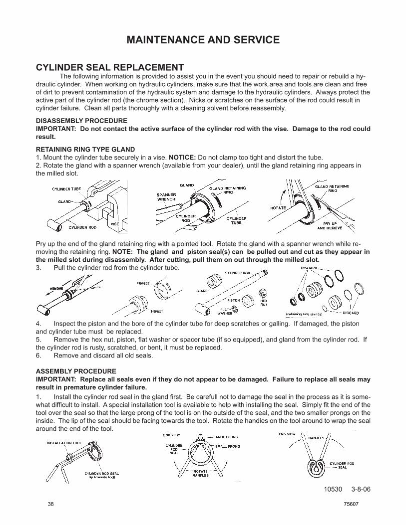
CYLINDER SEAL REPLACEMENT The following information is provided to assist you in the event you should need to repair or rebuild a hy-draulic cylinder. When working on hydraulic cylinders, make sure that the work area and tools are clean and free of dirt to prevent contamination of the hydraulic system and damage to the hydraulic cylinders. Always protect the active part of the cylinder rod (the chrome section). Nicks or scratches on the surface of the rod could result in cylinder failure. Clean all parts thoroughly with a cleaning solvent before reassembly.
DISASSEMBLY PROCEDUREIMPORTANT: Do not contact the active surface of the cylinder rod with the vise. Damage to the rod could result.
RETAINING RING TYPE GLAND1. Mount the cylinder tube securely in a vise. NOTICE: Do not clamp too tight and distort the tube. 2. Rotate the gland with a spanner wrench (available from your dealer), until the gland retaining ring appears in the milled slot.
Pry up the end of the gland retaining ring with a pointed tool. Rotate the gland with a spanner wrench while re-moving the retaining ring. NOTE: The gland and piston seal(s) can be pulled out and cut as they appear in the milled slot during disassembly. After cutting, pull them on out through the milled slot. 3. Pull the cylinder rod from the cylinder tube.
4. Inspect the piston and the bore of the cylinder tube for deep scratches or galling. If damaged, the piston and cylinder tube must be replaced. 5. Removethehexnut,piston,flatwasherorspacertube(ifsoequipped),andglandfromthecylinderrod.Ifthe cylinder rod is rusty, scratched, or bent, it must be replaced. 6. Remove and discard all old seals.
ASSEMBLY PROCEDUREIMPORTANT: Replace all seals even if they do not appear to be damaged. Failure to replace all seals may result in premature cylinder failure.1. Installthecylinderrodsealintheglandfirst.Becarefullnottodamagethesealintheprocessasitissome-whatdifficulttoinstall.Aspecialinstallationtoolisavailabletohelpwithinstallingtheseal.Simplyfittheendofthetool over the seal so that the large prong of the tool is on the outside of the seal, and the two smaller prongs on the inside. The lip of the seal should be facing towards the tool. Rotate the handles on the tool around to wrap the seal around the end of the tool.
38 75607
MAINTENANCE AND SERVICE
10531 3-8-06
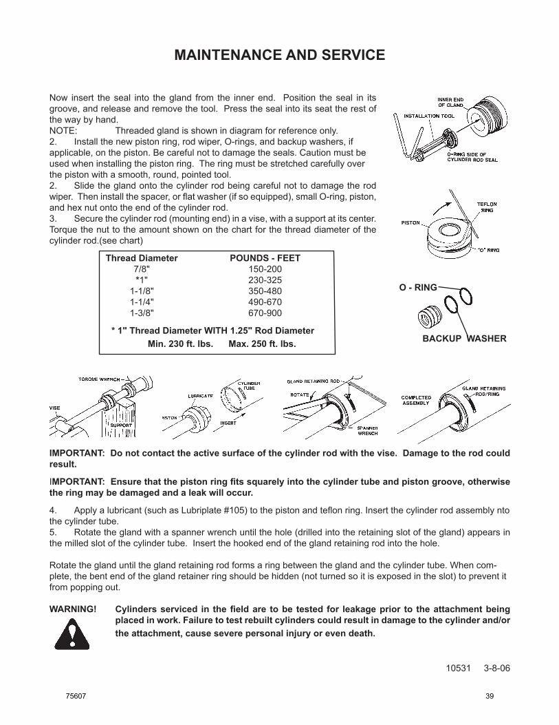
O - RING
BACKUP WASHER
Now insert the seal into the gland from the inner end. Position the seal in its groove, and release and remove the tool. Press the seal into its seat the rest of the way by hand.NOTE: Threaded gland is shown in diagram for reference only.2. Install the new piston ring, rod wiper, O-rings, and backup washers, if applicable,onthepiston.Becarefulnottodamagetheseals.Cautionmustbeused when installing the piston ring. The ring must be stretched carefully over the piston with a smooth, round, pointed tool.2. Slidetheglandontothecylinderrodbeingcarefulnottodamagetherodwiper.Theninstallthespacer,orflatwasher(ifsoequipped),smallO-ring,piston,and hex nut onto the end of the cylinder rod.3. Securethecylinderrod(mountingend)inavise,withasupportatitscenter.Torquethenuttotheamountshownonthechartforthethreaddiameterofthecylinder rod.(see chart)
* 1" Thread Diameter WITH 1.25" Rod Diameter Min. 230 ft. lbs. Max. 250 ft. lbs.
IMPORTANT: Do not contact the active surface of the cylinder rod with the vise. Damage to the rod could result.
IMPORTANT: Ensure that the piston ring fits squarely into the cylinder tube and piston groove, otherwise the ring may be damaged and a leak will occur.
4. Applyalubricant(suchasLubriplate#105)tothepistonandteflonring.Insertthecylinderrodassemblyntothe cylinder tube.5. Rotate the gland with a spanner wrench until the hole (drilled into the retaining slot of the gland) appears in the milled slot of the cylinder tube. Insert the hooked end of the gland retaining rod into the hole.
Rotate the gland until the gland retaining rod forms a ring between the gland and the cylinder tube. When com-plete, the bent end of the gland retainer ring should be hidden (not turned so it is exposed in the slot) to prevent it from popping out.
WARNING! Cylinders serviced in the field are to be tested for leakage prior to the attachment being placed in work. Failure to test rebuilt cylinders could result in damage to the cylinder and/or the attachment, cause severe personal injury or even death.
75607 39
MAINTENANCE AND SERVICE
10356 10-13-05
CYLINDER SEAL REPLACEMENT The following information is provided to assist you in the event you should need to repair or rebuild a hy-draulic cylinder. When working on hydraulic cylinders, make sure that the work area and tools are clean and free of dirt to prevent contamination of the hydraulic system and damage to the hydraulic cylinders. Always protect the active part of the cylinder rod (the chrome section). Nicks or scratches on the surface of the rod could result in cylinder failure. Clean all parts thoroughly with a cleaning solvent before reassembly.
DISASSEMBLY PROCEDUREIMPORTANT: Do not contact the active surface of the cylinder rod with the vise. Damage to the rod could result.
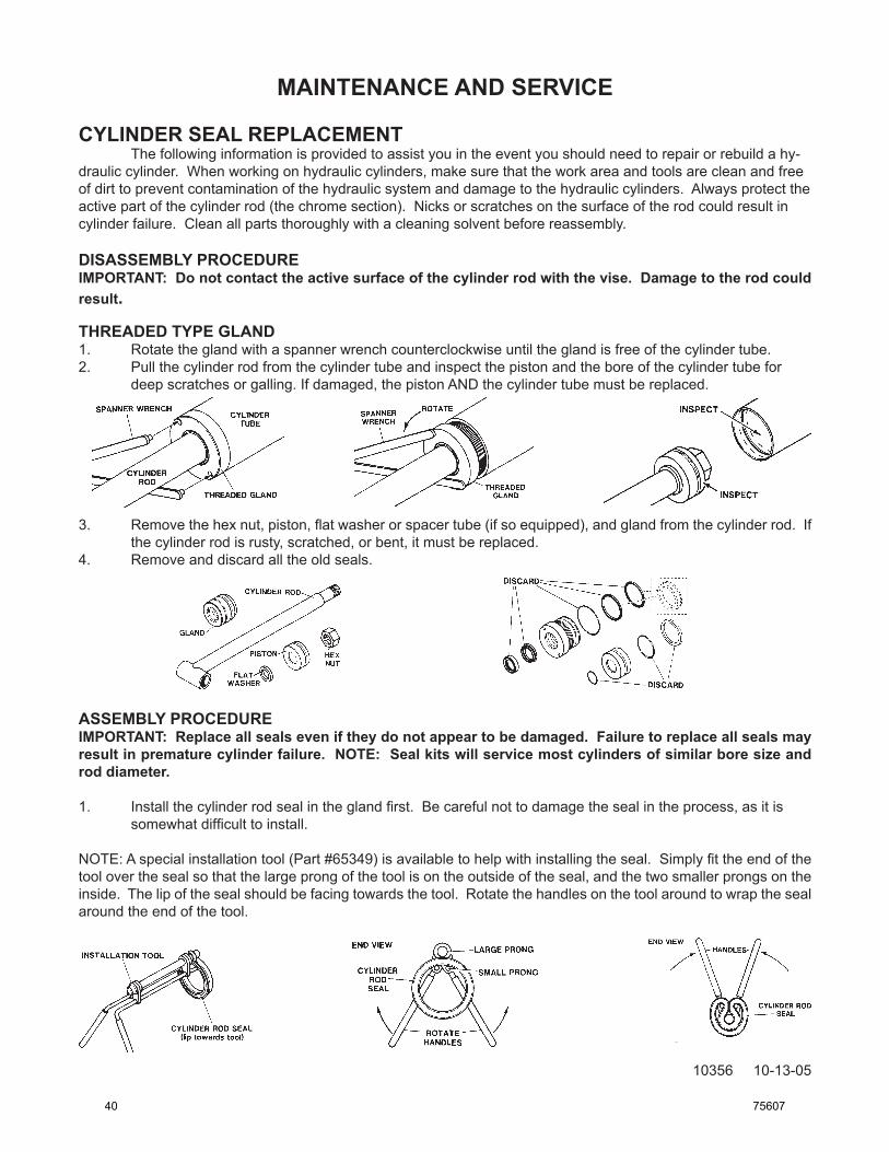
THREADED TYPE GLAND 1. Rotate the gland with a spanner wrench counterclockwise until the gland is free of the cylinder tube.2. Pull the cylinder rod from the cylinder tube and inspect the piston and the bore of the cylinder tube for
deep scratches or galling. If damaged, the piston AND the cylinder tube must be replaced.
3. Removethehexnut,piston,flatwasherorspacertube(ifsoequipped),andglandfromthecylinderrod.Ifthe cylinder rod is rusty, scratched, or bent, it must be replaced.
4. Remove and discard all the old seals.
ASSEMBLY PROCEDUREIMPORTANT: Replace all seals even if they do not appear to be damaged. Failure to replace all seals may result in premature cylinder failure. NOTE: Seal kits will service most cylinders of similar bore size and rod diameter.
NOTE:Aspecialinstallationtool(Part#65349)isavailabletohelpwithinstallingtheseal.Simplyfittheendofthetool over the seal so that the large prong of the tool is on the outside of the seal, and the two smaller prongs on the inside. The lip of the seal should be facing towards the tool. Rotate the handles on the tool around to wrap the seal around the end of the tool.
40 75607
MAINTENANCE AND SERVICE
10357 10-13-05
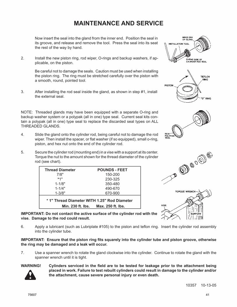
Now insert the seal into the gland from the inner end. Position the seal in its groove, and release and remove the tool. Press the seal into its seat the rest of the way by hand.
2. Install the new piston ring, rod wiper, O-rings and backup washers, if ap-plicable, on the piston.
Becarefulnottodamagetheseals.Cautionmustbeusedwheninstallingthe piston ring. The ring must be stretched carefully over the piston with a smooth, round, pointed tool.
3. After installing the rod seal inside the gland, as shown in step #1, install the external seal.
NOTE:ThreadedglandsmayhavebeenequippedwithaseparateO-ringandbackup washer system or a polypak (all in one) type seal. Current seal kits con-tain a polypak (all in one) type seal to replace the discarded seal types on ALL THREADED GLANDS.
4. Slide the gland onto the cylinder rod, being careful not to damage the rod wiper.Theninstallthespacer,orflatwasher(ifsoequipped),smallo-ring,piston, and hex nut onto the end of the cylinder rod.
5. Secure the cylinder rod (mounting end) in a vise with a support at its center. Torquethenuttotheamountshownforthethreaddiameterofthecylinderrod (see chart).
* 1" Thread Diameter WITH 1.25" Rod Diameter Min. 230 ft. lbs. Max. 250 ft. lbs.
IMPORTANT: Do not contact the active surface of the cylinder rod with thevise. Damage to the rod could result.
6. Applyalubricant(suchasLubriplate#105)tothepistonandteflonring.Insertthecylinderrodassemblyinto the cylinder tube.
IMPORTANT: Ensure that the piston ring fits squarely into the cylinder tube and piston groove, otherwise the ring may be damaged and a leak will occur.
7. Use a spanner wrench to rotate the gland clockwise into the cylinder. Continue to rotate the gland with the spanner wrench until it is tight.
WARNING! Cylinders serviced in the field are to be tested for leakage prior to the attachment being placed in work. Failure to test rebuilt cylinders could result in damage to the cylinder and/or the attachment, cause severe personal injury or even death.
75607 41
TROUBLESHOOTING
10666 8-10-06
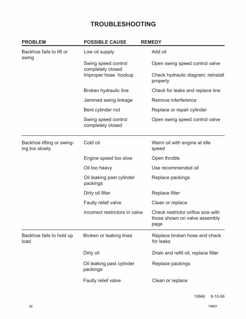
PROBLEM POSSIBLECAUSE REMEDY
Backhoe fails to lift or Low oil supply Add oilswing Swing speed control Open swing speed control valve completely closed Improper hose hookup Check hydraulic diagram; reinstall properly
Broken hydraulic line Check for leaks and replace line
Jammed swing linkage Remove interference
Bent cylinder rod Replace or repair cylinder
Swing speed control Open swing speed control valve completely closed
Backhoe lifting or swing- Cold oil Warm oil with engine at idleing too slowly speed
Engine speed too slow Open throttle
Oil too heavy Use recommended oil
Oil leaking past cylinder Replace packings packings
Dirtyoilfilter Replacefilter
Faulty relief valve Clean or replace
Incorrectrestrictorsinvalve Checkrestrictororificesizewith those shown on valve assembly page
Backhoe fails to hold up Broken or leaking lines Replace broken hose and checkload for leaks
Dirtyoil Drainandrefilloil,replacefilter
Oil leaking past cylinder Replace packings packings
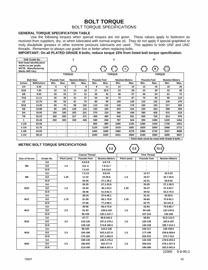
GENERAL TORQUE SPECIFICATION TABLE Use the following torques when special torques are not given. These values apply to fasteners as received from suppliers, dry, or when lubricated with normal engine oil. They do not apply if special graphited or moly disulphide greases or other extreme pressure lubricants are used. This applies to both UNF and UNC threads. Remember to always use grade five or better when replacing bolts. IMPORTANT: On all PLATED GRADE 8 bolts, reduce torque 15% from listed bolt torque specification.
SAE Grade No. 2 5 8* Bolt head identification marks as per grade. NOTE: Manufacturing Marks Will Vary
TORQUE TORQUE TORQUE
Bolt Size
Pounds Feet
Newton-Meters
Pounds Feet
Newton-Meters
Pounds Feet
Newton-Meters Inches Millimeters Min. Max. Min. Max. Min. Max. Min. Max. Min. Max. Min. Max.
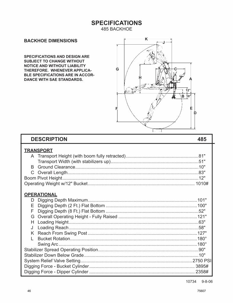
TRANSPORT A Transport Height (with boom fully retracted) .........................................................81" Transport Width (with stabilizers up) .....................................................................51" B Ground Clearance .................................................................................................10" C Overall Length .......................................................................................................83" Boom Pivot Height ...........................................................................................................12" Operating Weight w/12" Bucket .................................................................................... 1010#
OPERATIONAL D Digging Depth Maximum ......................................................................................101" E Digging Depth (2 Ft.) Flat Bottom ........................................................................100" F Digging Depth (8 Ft.) Flat Bottom .........................................................................52" G Overall Operating Height - Fully Raised ..............................................................121" H Loading Height ......................................................................................................63" J Loading Reach ......................................................................................................58" K Reach From Swing Post ......................................................................................127" L Bucket Rotation ....................................................................................................180° Swing Arc .............................................................................................................180° Stabilizer Spread Operating Position ...............................................................................90" Stabilizer Down Below Grade ..........................................................................................10" System Relief Valve Setting........................................................................................2750 PSI Digging Force - Bucket Cylinder ................................................................................... 3895# Digging Force - Dipper Cylinder ................................................................................... 2358#
BACKHOEDIMENSIONS
SPECIFICATIONSANDDESIGNARESUBJECTTOCHANGEWITHOUTNOTICEANDWITHOUTLIABILITYTHEREFORE.WHENEVERAPPLICA-BLESPECIFICATIONSAREINACCOR-DANCEWITHSAESTANDARDS. A
BACKHOE CHECKLISTFOR USE WITH BACKHOES AND BACKHOE MOUNTING KITS
DEALER RESPONSIBILITY:The following check list is to be completed by the equipment dealer. This checklist is to be completed by the dealer at time of delivery. When purchasing a mounting kit for an existing backhoe it is the equipment dealers responsibility to review this checklist with the customer and instruct them to check each item at time of installation onto their prime mover.
BACKHOE:1. _____ Check and lubricate backhoe. See “Lubrication Section” in Operator’s Manual.2. _____ Visually inspect the backhoe for bent, loose, cracked, damaged or missing parts or any other irregularities
prior to operation.3. _____ Verify backhoe control lever function and direction of operation are in accordance with the control lever
decals.4. _____ Run cylinders through their full cycle to purge any air from the system. Recheck hydraulic system for cor-
rect hydraulic fluid levels.5. _____ Check all hydraulic connections for leaks and all hoses for proper positioning to reduce chafing and bind-
ing.6. _____ Check prime mover system relief valve pressure and compare and adjust to recommended operating
pressure listed in the “Specifications Section” of the Operator’s Manual. 7. _____ Make sure decals are not damaged or missing and are in their right location. See “Decals Section” of the
Operator’s Manual.8. _____ Customer instructed to read and understand Operator’s Manual before operating backhoe. 9. _____ Complete and return the manufacturers “Warranty Validation Form”.
MOUNTING:1. _____ Check backhoe, mounting, and prime mover to ensure they are all compatible.2. _____ Check backhoe mounting bolts for tightness. Instruct owner to retighten after the first eight working
hours, and after every forty working hour interval thereafter. See “Bolt Torque Specifications” in Opera-tor’s Manual.
3. _____ If customer is installing the mounts and mounting the backhoe to the prime mover, the dealer must review the proper mounting procedure and possible consequences of improper installation.
4. _____ Verify the owner is in possession of an operator’s manual and instruct them to read and understand all safety and operating techniques.
OWNERS RESPONSIBILITY: It is the owner’s responsibility to make sure that the dealer has completed this checklist and instructed him/her on safe and proper operation of the backhoe. If installation instructions are unclear, bring backhoe, mounting and prime mover to the equipment dealership for proper installation.
Owner’sSignature Date
DealershipSignature Date
F-1228 5-14-1075607 49
THIS PAGEIS INTENTIONALLY
BLANK
50 75607
Limited WarrantyExcept for the Excluded Products as described below, all new products are warranted to be free from defects in material and/or workmanship during the Warranty Period, in accordance with and subject to the terms and conditions of this Limited Warranty.
1. Excluded Products. The following products are excluded from this Limited Warranty:
(a) Any cable, part that engages with the ground (i.e. sprockets), digging chain, bearing, teeth, tamping and/or demolition head, blade cutting edge, pilot bit, auger teeth and broom brush that either constitutes or is part of a product.
(b) Any product, merchandise or component that, in the opinion of Paladin Light Construction1, has been (i) misused; (ii) modified in any unauthorized manner; (iii) altered; (iv) damaged; (v) involved in an accident; or (vi) repaired using parts not obtained through Paladin Light Construction.
2. Warranty Period. The Limited Warranty is provided only to those defects that occur during the Warranty Period, which is the period that begins on the first to occur of: (i) the date of initial purchase by an end-user, (ii) the date the product is first leased or rented, or (iii) the date that is six (6) months after the date of shipment by Paladin Light Construction as evidenced by the invoiced shipment date (the “Commencement Date”) and ends on the date that is twenty-four (24) months after the Commencement Date.
3. Terms and Conditions of Limited Warranty. The following terms and conditions apply to the Limited Warranty hereby provided:
(a) Option to Repair or Replace. Paladin Light Construction shall have the option to repair or replace the product.
(b) Timely Repair and Notice. In order to obtain the Limited Warranty, (i) the product must be repaired within thirty (30) days from the date of failure, and (ii) a claim under the warranty must be submitted to Paladin Light Construction in writing within thirty (30) days from the date of repair.
(c) Return of Defective Part or Product. If requested by Paladin Light Construction, the alleged defective part or product shall be shipped to Paladin Light Construction at its manufacturing facility or other location specified by Paladin Light Construction, with freight PRE-PAID by the claimant, to allow Paladin Light Construction to inspect the part or product.
Claims that fail to comply with any of the above terms and conditions shall be denied.
LIMITATIONS AND EXCLUSIONS.
THIS LIMITED WARRANTY IS IN LIEU OF ALL OTHER WARRANTIES, EXPRESS OR IMPLIED, INCLUDING WITHOUT LIMITATION THE WARRANTIES OF MERCHANTABILITY, FITNESS FOR A PARTICULAR PURPOSE AND ANY WARRANTY BASED ON A COURSE OF DEALING OR USAGE OF TRADE.
IN NO EVENT SHALL PALADIN LIGHT CONSTRUCTION BE LIABLE FOR CONSEQUENTIAL OR SPECIAL DAMAGES.
IN NO EVENT SHALL PALADIN LIGHT CONSTRUCTION BE LIABLE FOR ANY LOSS OR CLAIM IN AN AMOUNT IN EXCESS OF THE PURCHASE PRICE, OR, AT THE OPTION OF PALADIN LIGHT CONSTRUCTION, THE REPAIR OR REPLACEMENT, OF THE PARTICULAR PRODUCT ON WHICH ANY CLAIM OF LOSS OR DAMAGE IS BASED. THIS LIMITATION OF LIABILITY APPLIES IRRESPECTIVE OF WHETHER THE CLAIM IS BASED ON BREACH OF CONTRACT, BREACH OF WARRANTY, NEGLIGENCE OR OTHER CAUSE AND WHETHER THE ALLEGED DEFECT IS DISCOVERABLE OR LATENT.
1Attachment Technologies Inc., a subsidiary of Paladin Brands Holding, Inc. (PBHI) is referred to herein as Paladin Light Construction.